KR20200029005A - Inspection device and handle for inspection device - Google Patents
Inspection device and handle for inspection device Download PDFInfo
- Publication number
- KR20200029005A KR20200029005A KR1020207004155A KR20207004155A KR20200029005A KR 20200029005 A KR20200029005 A KR 20200029005A KR 1020207004155 A KR1020207004155 A KR 1020207004155A KR 20207004155 A KR20207004155 A KR 20207004155A KR 20200029005 A KR20200029005 A KR 20200029005A
- Authority
- KR
- South Korea
- Prior art keywords
- compartment
- housing portion
- trigger
- seal
- inspection device
- Prior art date
- Legal status (The legal status is an assumption and is not a legal conclusion. Google has not performed a legal analysis and makes no representation as to the accuracy of the status listed.)
- Granted
Links
Images



Classifications
-
- G—PHYSICS
- G01—MEASURING; TESTING
- G01N—INVESTIGATING OR ANALYSING MATERIALS BY DETERMINING THEIR CHEMICAL OR PHYSICAL PROPERTIES
- G01N29/00—Investigating or analysing materials by the use of ultrasonic, sonic or infrasonic waves; Visualisation of the interior of objects by transmitting ultrasonic or sonic waves through the object
- G01N29/22—Details, e.g. general constructional or apparatus details
- G01N29/225—Supports, positioning or alignment in moving situation
- G01N29/226—Handheld or portable devices
-
- B—PERFORMING OPERATIONS; TRANSPORTING
- B25—HAND TOOLS; PORTABLE POWER-DRIVEN TOOLS; MANIPULATORS
- B25F—COMBINATION OR MULTI-PURPOSE TOOLS NOT OTHERWISE PROVIDED FOR; DETAILS OR COMPONENTS OF PORTABLE POWER-DRIVEN TOOLS NOT PARTICULARLY RELATED TO THE OPERATIONS PERFORMED AND NOT OTHERWISE PROVIDED FOR
- B25F5/00—Details or components of portable power-driven tools not particularly related to the operations performed and not otherwise provided for
- B25F5/02—Construction of casings, bodies or handles
-
- G—PHYSICS
- G01—MEASURING; TESTING
- G01D—MEASURING NOT SPECIALLY ADAPTED FOR A SPECIFIC VARIABLE; ARRANGEMENTS FOR MEASURING TWO OR MORE VARIABLES NOT COVERED IN A SINGLE OTHER SUBCLASS; TARIFF METERING APPARATUS; MEASURING OR TESTING NOT OTHERWISE PROVIDED FOR
- G01D11/00—Component parts of measuring arrangements not specially adapted for a specific variable
- G01D11/24—Housings ; Casings for instruments
- G01D11/245—Housings for sensors
-
- G—PHYSICS
- G01—MEASURING; TESTING
- G01N—INVESTIGATING OR ANALYSING MATERIALS BY DETERMINING THEIR CHEMICAL OR PHYSICAL PROPERTIES
- G01N29/00—Investigating or analysing materials by the use of ultrasonic, sonic or infrasonic waves; Visualisation of the interior of objects by transmitting ultrasonic or sonic waves through the object
- G01N29/22—Details, e.g. general constructional or apparatus details
- G01N29/24—Probes
- G01N29/2412—Probes using the magnetostrictive properties of the material to be examined, e.g. electromagnetic acoustic transducers [EMAT]
-
- G—PHYSICS
- G01—MEASURING; TESTING
- G01N—INVESTIGATING OR ANALYSING MATERIALS BY DETERMINING THEIR CHEMICAL OR PHYSICAL PROPERTIES
- G01N2291/00—Indexing codes associated with group G01N29/00
- G01N2291/26—Scanned objects
-
- G—PHYSICS
- G01—MEASURING; TESTING
- G01N—INVESTIGATING OR ANALYSING MATERIALS BY DETERMINING THEIR CHEMICAL OR PHYSICAL PROPERTIES
- G01N27/00—Investigating or analysing materials by the use of electric, electrochemical, or magnetic means
- G01N27/72—Investigating or analysing materials by the use of electric, electrochemical, or magnetic means by investigating magnetic variables
- G01N27/82—Investigating or analysing materials by the use of electric, electrochemical, or magnetic means by investigating magnetic variables for investigating the presence of flaws
- G01N27/83—Investigating or analysing materials by the use of electric, electrochemical, or magnetic means by investigating magnetic variables for investigating the presence of flaws by investigating stray magnetic fields
- G01N27/84—Investigating or analysing materials by the use of electric, electrochemical, or magnetic means by investigating magnetic variables for investigating the presence of flaws by investigating stray magnetic fields by applying magnetic powder or magnetic ink
Landscapes
- Physics & Mathematics (AREA)
- General Physics & Mathematics (AREA)
- Chemical & Material Sciences (AREA)
- Immunology (AREA)
- Life Sciences & Earth Sciences (AREA)
- Analytical Chemistry (AREA)
- Biochemistry (AREA)
- General Health & Medical Sciences (AREA)
- Pathology (AREA)
- Health & Medical Sciences (AREA)
- Mechanical Engineering (AREA)
- Engineering & Computer Science (AREA)
- Electromagnetism (AREA)
- Chemical Kinetics & Catalysis (AREA)
- Electrochemistry (AREA)
- Examining Or Testing Airtightness (AREA)
- Testing Resistance To Weather, Investigating Materials By Mechanical Methods (AREA)
- Switch Cases, Indication, And Locking (AREA)
- Investigating Or Analyzing Materials By The Use Of Magnetic Means (AREA)
- Investigating Strength Of Materials By Application Of Mechanical Stress (AREA)
- Automatic Analysis And Handling Materials Therefor (AREA)
- Power Steering Mechanism (AREA)
Abstract
검사 장치 및 검사 장치용 핸들이 개시된다. 예시적인 검사 장치는 제1 구획부와 트리거 구획을 포함하는 제1 하우징부; 제1 구획부에 상보적인 제2 구획부를 포함하는 제2 하우징부로서, 제1 하우징부와 제2 하우징부가 부착될 때에 제1 구획부와 제2 구획부가 요크 구획을 형성하는 것인 제2 하우징부; 제1 구획부 또는 제2 구획부 중 하나 이상의 둘레 주위에 위치 설정되고, 요크 구획을 밀봉하기 위해 제1 하우징부와 제2 하우징부 사이에서 압박되도록 구성된 제거형 시일; 및 제1 하우징부의 트리거 구획에 상보적이고, 제2 하우징부와 함께 제1 하우징부에 제거 가능하게 부착되는 트리거 커버를 포함한다.Disclosed is an inspection device and a handle for an inspection device. An exemplary inspection device includes a first housing portion comprising a first compartment and a trigger compartment; A second housing part including a second compartment complementary to the first compartment, wherein the first compartment and the second compartment form a yoke compartment when the first and second housing parts are attached. part; A removable seal positioned around the perimeter of at least one of the first compartment or the second compartment and configured to be pressed between the first housing part and the second housing part to seal the yoke compartment; And a trigger cover complementary to the trigger section of the first housing portion, and removably attached to the first housing portion together with the second housing portion.
Description
관련 출원Related applications
본 국제 출원은 발명이 명칭이 “검사 장치 및 검사 장치용 핸들”이고 2018년 7월 10일자로 출원된 미국 특허 출원 제16/031,522호 및 발명이 명칭이 “검사 장치용 핸들”이고 2017년 7월 14일자로 출원된 미국 가특허 출원 제62/532,893호에 대한 우선권을 주장한다. 미국 특허 출원 제16/031,522호 및 미국 가특허 출원 제62/532,893호의 전체 내용은 참조에 의해 여기에 포함된다.In this international application, the invention is entitled “Inspection device and handle for inspection device” and U.S. Patent Application No. 16 / 031,522, filed July 10, 2018, and the invention is named “Handle for inspection device”, and 2017. Claims priority to U.S. Provisional Patent Application No. 62 / 532,893 filed on May 14th. The entire contents of U.S. Patent Application No. 16 / 031,522 and U.S. Provisional Patent Application No. 62 / 532,893 are incorporated herein by reference.
본 개시는 일반적으로 휴대용 공구에 관한 것으로, 보다 구체적으로는 검사 장치 및 검사 장치용 핸들에 관한 것이다. The present disclosure relates generally to portable tools, and more particularly to inspection devices and handles for inspection devices.
자기 입자 검사를 위해 사용되는 전자기 요크(electromagnetic yoke)와 같은 일부 비파괴 검사 장치는 통상적인 사용 중에 습윤 환경에 노출된다. 그 결과, 상기한 비파괴 검사 장치 및 비파괴 검사 장치의 전기 구성요소는 유체와 접촉할 수 있다. 종래의 습윤 환경 검사 장치는 통상적으로 중량의 주입 가공형(poured) 엘라스토머 하우징으로 구성된다. 쉽게 이해할 수 있는 바와 같이, 상기한 검사 장치는 중량으로 인해 조작하기 어렵고 고체 몰딩으로 인해 점검하기 어려우며, 연장된 사용 코스에 걸쳐 오퍼레이터에게 피로를 초래할 수 있다.Some non-destructive testing devices, such as electromagnetic yokes used for magnetic particle inspection, are exposed to a wet environment during normal use. As a result, the non-destructive testing device described above and the electrical components of the non-destructive testing device may be in contact with the fluid. Conventional wet environment testing devices typically consist of a heavy-poured elastomeric housing. As can be easily understood, the above-described inspection device is difficult to operate due to weight, difficult to inspect due to solid molding, and may cause operator fatigue over an extended course of use.
청구범위에 보다 완벽하게 기술된 바와 같은 검사 장치 및 검사 장치용 핸들은 실질적으로 도면들 중 적어도 하나와 연계되어 예시되는 것과 같이 개시된다.Inspection devices and handles for inspection devices as more fully described in the claims are disclosed as substantially illustrated in connection with at least one of the drawings.
이들 및/또는 다른 양태는 첨부도면과 함께 취해지는 예시적인 실시예에 관한 아래의 설명으로부터 명백해질 것이고 보다 용이하게 이해될 것이다.
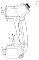
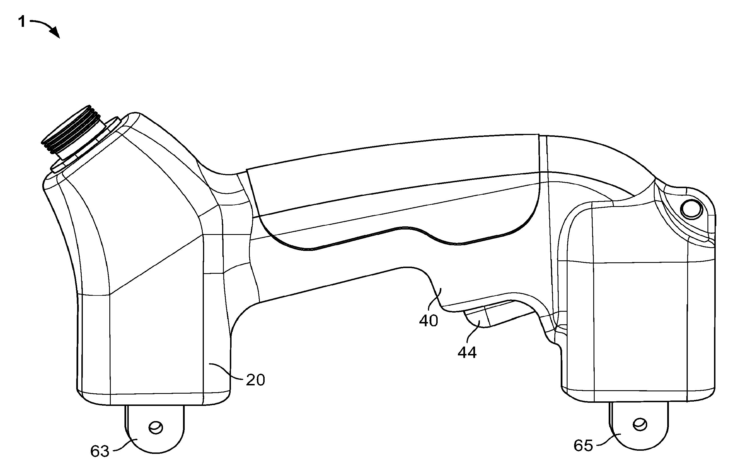
도 1은 본 개시의 양태에 따른 검사 장치의 사시도이다.
도 2는 도 1의 예시적인 검사 장치에서의 일부의 내부의 측면도이다.
도 3a는 도 1의 예시적인 검사 장치의 제1 하우징부의 측면도이다.
도 3b는 도 1의 예시적인 검사 장치의 트리거 커버의 측면도이다.
도 3c는 도 1의 예시적인 검사 장치의 제2 하우징부의 측면도이다.
도 4는 도 1의 예시적인 검사 장치의 제1 하우징부에 부착된 트리거 커버의 측면도이다.
도 5는 도 1의 예시적인 검사 장치의 트리거 커버와 제1 하우징부의 분해도이다.
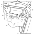
도 6a 및 도 6b는 도 1의 예시적인 검사 장치의 트리거 구획의 상세도이다.
도면들이 반드시 실축척에 맞는 것은 아니다. 적절하다면, 유사하거나 동일한 구성요소를 인용하기 위해 유사하거나 동일한 참조부호가 사용된다.These and / or other aspects will become apparent from the following description of exemplary embodiments taken in conjunction with the accompanying drawings and will be more readily understood.
1 is a perspective view of an inspection apparatus according to aspects of the present disclosure.
FIG. 2 is an internal side view of a portion of the exemplary inspection device of FIG. 1;
3A is a side view of the first housing portion of the exemplary inspection device of FIG. 1;
3B is a side view of the trigger cover of the exemplary inspection device of FIG. 1.
3C is a side view of the second housing portion of the exemplary inspection device of FIG. 1.
4 is a side view of the trigger cover attached to the first housing portion of the exemplary inspection device of FIG. 1.
5 is an exploded view of the trigger cover and the first housing portion of the exemplary inspection device of FIG. 1.
6A and 6B are detailed views of the trigger section of the exemplary inspection device of FIG. 1.
The drawings are not necessarily to scale. Where appropriate, similar or identical reference numerals are used to refer to similar or identical components.
개시된 예시적인 검사 장치는 제1 구획부와 트리거 구획을 포함하는 제1 하우징부; 제1 구획부에 상보적인 제2 구획부를 포함하는 제2 하우징부로서, 제1 하우징부와 제2 하우징부가 부착될 때에 제1 구획부와 제2 구획부가 요크 구획을 형성하는 것인 제2 하우징부; 제1 구획부 또는 제2 구획부 중 하나 이상의 둘레 주위에 위치 설정되고, 요크 구획을 밀봉하기 위해 제1 하우징부와 제2 하우징부 사이에서 압박되도록 구성된 제거형 시일; 및 제1 하우징부의 트리거 구획에 상보적이고, 제2 하우징부와 함께 제1 하우징부에 제거 가능하게 부착되는 트리거 커버를 포함한다. The disclosed exemplary inspection device includes a first housing portion including a first compartment and a trigger compartment; A second housing part including a second compartment complementary to the first compartment, wherein the first compartment and the second compartment form a yoke compartment when the first and second housing parts are attached. part; A removable seal positioned around the perimeter of at least one of the first compartment or the second compartment and configured to be pressed between the first housing part and the second housing part to seal the yoke compartment; And a trigger cover complementary to the trigger section of the first housing portion, and removably attached to the first housing portion together with the second housing portion.
몇몇 예시적인 검사 장치에서, 트리거 커버는 제1 하우징부로부터 제2 하우징부를 분리하지 않으면서 제1 하우징부로부터 분리 가능하다. 몇몇 예는 전기 스위치, 스프링 및 트리거 구획 내에 위치 설정되는 액추에이터를 더 포함하고, 트리거 커버와 트리거 구획은 부착 시에 전기 스위치, 스프링 및 액추에이터를 밀폐하도록 구성된다. 몇몇 예에서, 스프링은 액슬 주위에서 액추에이터에 의해 회전 가능하게 하중을 받는 토션 스프링이다. 몇몇 예에서, 전기 스위치는 트리커 커버를 제거하는 것에 의해 교체 가능한 밀봉된 전기 스위치이다. In some exemplary inspection devices, the trigger cover is detachable from the first housing portion without removing the second housing portion from the first housing portion. Some examples further include actuators positioned within the electrical switch, spring, and trigger compartment, and the trigger cover and trigger compartment are configured to seal the electrical switch, spring, and actuator upon attachment. In some examples, the spring is a torsion spring that is rotatably loaded by an actuator around the axle. In some examples, the electrical switch is a sealed electrical switch that is replaceable by removing the triker cover.
몇몇 예시적인 검사 장치에서, 제거형 시일은 트리거 커버가 제거될 때에 제1 하우징부와 제2 하우징부 사이에서 압박된다. 몇몇 예에서, 제거형 시일은 요크 구획에 대한 이물 침입 방지를 제공한다. 몇몇 예에서, 제2 하우징부와 트리거 커버는 복수 개의 파스너에 의해 제1 하우징부에 제거 가능하게 부착된다. 몇몇 예에서, 제1 하우징부, 제2 하우징부 또는 트리거 커버 중 하나 이상은 사출 성형된다. In some exemplary inspection devices, the removable seal is pressed between the first housing portion and the second housing portion when the trigger cover is removed. In some examples, the removable seal provides foreign body intrusion prevention into the yoke compartment. In some examples, the second housing portion and the trigger cover are removably attached to the first housing portion by a plurality of fasteners. In some examples, one or more of the first housing portion, the second housing portion, or the trigger cover is injection molded.
몇몇 예에서, 제1 하우징부는 제1 레그 구멍 및 제2 레그 구멍을 포함한다. 몇몇 예시적인 검사 장치는 요크 구획 내에 배치되는 제1 전자기 코일; 요크 구획 내에 배치되는 제2 전자기 코일; 및 제1 레그 구멍, 제1 전자기 코일, 요크 구획, 제2 전자기 코일 및 제2 레그 구멍을 통해 연장되는 코어를 더 포함한다. 몇몇 예에서, 코어는 수지에 의해 제1 레그 구멍에서 밀봉되고, 코어는 수지에 의해 제2 레그 구멍에서 밀봉된다. 몇몇 예는 제1 레그 구멍을 밀봉하도록 구성된 제1 레그 시일 및 제2 레그 구멍을 밀봉하도록 구성된 제2 레그 시일을 더 포함한다. 몇몇 예에서, 제1 레그 시일은 코어의 두께 범위에 있어서 제1 하우징부 또는 제2 하우징부 중 하나 이상과 코어에 대해 밀봉하도록 구성된 컨포밍 재료(conforming material)를 포함한다. In some examples, the first housing portion includes a first leg hole and a second leg hole. Some exemplary inspection devices include a first electromagnetic coil disposed within a yoke compartment; A second electromagnetic coil disposed in the yoke compartment; And a core extending through the first leg hole, the first electromagnetic coil, the yoke section, the second electromagnetic coil, and the second leg hole. In some examples, the core is sealed in the first leg hole by resin, and the core is sealed in the second leg hole by resin. Some examples further include a first leg seal configured to seal the first leg hole and a second leg seal configured to seal the second leg hole. In some examples, the first leg seal includes a forming material configured to seal against the core and one or more of the first housing portion or the second housing portion in a thickness range of the core.
몇몇 예시적인 검사 장치에서, 제1 하우징부는 제1 구획부의 둘레 주위에 제거형 시일을 수용하도록 구성된 채널을 포함한다. 몇몇 예시적인 검사 장치는 제1 하우징부의 채널에 있는 와이어 구멍 - 제거형 시일이 이 와이어 구멍에 놓이도록 구성됨 - ; 및 요크 구획과 트리거 구획 사이에서 와이어 구멍을 횡단하도록 구성된 복수 개의 와이어를 더 포함한다. 몇몇 예에서, 복수 개의 와이어는 수지 또는 포팅 컴파운드(potting compound) 중 하나 이상에 의해 와이어 구멍에서 밀봉된다. 몇몇 예에서, 방수 커넥터가 트리거 구획에 있는 전기 스위치의 복수 개의 와이어와 복수 개의 리드에 대해 적용된다. 몇몇 예에서, 복수 개의 와이어는 적어도 하나의 여분의 길이의 서브섹션을 포함한다. In some exemplary inspection devices, the first housing portion includes a channel configured to receive the removable seal around the perimeter of the first compartment. Some exemplary inspection devices include a wire hole in the channel of the first housing portion-a removable seal is configured to lie in this wire hole; And a plurality of wires configured to traverse the wire holes between the yoke section and the trigger section. In some examples, the plurality of wires are sealed in the wire holes by one or more of resin or potting compound. In some examples, a waterproof connector is applied to multiple wires and multiple leads of the electrical switch in the trigger compartment. In some examples, the plurality of wires includes at least one extra length subsection.
몇몇 예시적인 검사 장치에서, 제1 하우징부는 전력 플러그 구멍을 포함하고, 검사 장치는 제거형 플러그를 포함하며, 제거형 플러그는 이 제거형 플러그와 요크 구획에 있는 하나 이상의 구성요소 사이에서 전력 전류를 전도하도록 구성된다. In some exemplary inspection devices, the first housing portion includes a power plug hole, the inspection device includes a removable plug, and the removable plug draws electrical power current between the removable plug and one or more components in the yoke compartment. It is configured to conduct.
도 1은, 자기 입자 검사를 위해 사용되는 전자기 요크인 예시적인 검사 장치(1)를 예시한다. 검사 장치(1)는 제1 하우징부(10), 제2 하우징부(20) 및 트리거 커버(40)를 포함한다. 제1 하우징부(10)와 제2 하우징부(20)는 결합 또는 부착될 때에 예시적인 검사 장치(1)의 전자기 구성요소를 포함하는 요크 구획(17)을 형성한다. 제2 하우징부(20)와 트리거 커버(40)는 복수 개의 나사(50), 리벳 및/또는 임의의 다른 타입의 파스너에 의해 개별적으로 제거 가능하게 제1 하우징부(10)에 부착된다. 1 illustrates an exemplary inspection device 1 which is an electromagnetic yoke used for magnetic particle inspection. The inspection device 1 includes a
검사 장치(1)는 통상 습윤 환경에서 사용된다. 자기 입자 용액이 검사하는 아이템에 주입되거나 도포된다. 그 후, 전자기 요크를 사용하여 검사받는 아이템에 자기장을 인가한다. 사용자는 적어도 하나의 전자기(EM) 코일(62, 64)(도 2에 예시됨)을 활성화시키기 위해 검사 장치(1) 상의 트리거 또는 액추에이터(44)를 누른다. 코어(66)는 제1 전자기 코일(62), 요크 구획(17) 및 제2 전자기 코일(64)을 통해 연장된다. 코어(66)는 제1 레그(63)에서 종결되고, 제2 레그(65)는 검사받는 아이템에 접촉하도록 검사 장치(1)에서부터 연장된다. 예시적인 코어(66)는 강자성재로 이루어진 다수의 층상물을 사용하여 구성된다. The inspection device 1 is usually used in a wet environment. A magnetic particle solution is injected or applied to the item being inspected. Thereafter, a magnetic field is applied to the item to be inspected using an electromagnetic yoke. The user presses the trigger or
도 2는 검사 장치(1)의 내부를 예시한다. 제1 하우징부(10)는, 제1 전자기 코일(62)과 제2 전자기 코일(64)이 배치되는 제1 구획부(12)를 포함한다. 와이어와 접촉 바가 코일(62, 64)을 전원에 접속시킨다[파워 플러그 구멍(19)을 통해 입력함]. 제거형 플러그(21)가 파워 플러그 구멍(19)에 탈착식으로 접속되고, 파워 플러그 구멍(19)을 습기 또는 다른 이물질에 의한 침입에 대해 밀봉한다. 예시적인 제거형 플러그(21)는 전원에 접속될 수 있고, 요크 구획(17) 내의 배선을 통해 전력을 코일(62, 64)로 전달한다. 2 illustrates the interior of the inspection device 1. The
코어(66)는 제1 EM 코일(62)에서부터 제1 레그 구멍(16)을 통해 연장되고, 제1 레그(63)에서 종결된다. 이와 유사하게, 코어는 제2 EM 코일(64)에서부터 제2 레그 구멍(18)을 통해 연장되고, 제2 레그(65)에서 종결된다. 몇몇 예에서, 코어(66) 및/또는 제1 레그(63)는 수지(15)에 의해 제1 레그 구멍(16)에서 밀봉되고, 제2 레그(65) 및/또는 코어(66)는 수지(15)에 의해 제2 레그 구멍(18)에서 밀봉된다. 추가로 또는 대안으로서, 제1 레그(63), 제2 레그(65) 및/또는 코어(66)는, 코어(66) 및/또는 제1 레그(63)나 제2 레그(65)에 대해 그리고 제1 하우징부(10) 및/또는 제2 하우징부(20)에 대해 밀봉하도록 구성된 컨포밍 재료에 의해 제1 레그 구멍(16) 및/또는 제2 레그 구멍(18)에서 밀봉된다. 수지(15) 또는 컨포밍 재료는, 코어(66)를 구성하는 데 사용되는 층상물의 두께에서의 잠재적인 변형에도 불구하고 구멍(16, 18)이 밀봉되게 할 수 있다. The
제2 하우징부(20)(도 3c에 예시함)는 제1 하우징부(10)에 결합된다. 하우징부(10, 20)들 사이에 제거형 시일(30)이 위치 설정된다. 시일(30)은 (제한하는 것은 아니지만, 예컨대 물 및 미립자에 대한) 이물 침입 방지를 제공한다. 예시된 예에서, 시일(30)은 제1 하우징부(10)의 채널(13) 내에 배치된다. 시일(30)은 하우징부(10, 20)들을 함께 결합시키고, 시일(30)의 압축으로 인한 이물 침입 방지를 제공한다. 제거형 시일(30)은 제한하는 것은 아니지만, 가스켓 또는 O-링일 수 있다. 도 2에 예시한 바와 같이, 제거형 시일(30)은 제1 구획부의 둘레 주위에 위치 설정되고, [도 2에서 트리거 커버(40)에 의해 커버되는] 트리거 구획(14)을 배제한다. 시일(30)은 제1 레그 구멍(16)과 제2 레그 구멍(18)을 횡단한다. The second housing portion 20 (illustrated in FIG. 3C) is coupled to the
도 3a는, 제1 구획부(12)와 트리거 구획(14)을 포함하는 제1 하우징부(10)를 예시한다. (제거형 시일(30)이 배치되는) 둘레부/채널(13)은 제1 구획부(12)를 둘러싸고, 트리거 구획(14)을 배제한다. 이에 따라, 제거형 시일(30)은 EM 코일과 관련 전기 구성요소를 위한 이물 침입 방지를 제공한다. 제1 하우징부(10)는 제2 하우징부(20)를 수용하여, 제1 구획부(12)와 제2 구획부(22)(도 3c에 예시함) 사이에 요크 구획(17)을 완성한다. 추가로, 제1 하우징부(10)는 트리거 커버(40)(도 3b에 예시함)를 수용한다. 3A illustrates a
도 3b는 검사 장치(1)의 트리거 커버(40)를 예시한다. 트리거 커버(40)는 플라스틱으로 사출 성형된다. 몇몇 실시예에서, 제1 하우징부(10)와 제2 하우징부(2)도 마찬가지로 사출 성형된다. 트리거 커버(40) 형상은 제1 하우징부(10)의 트리거 구획(14)에 상보적이다. 트리거 커버(40)는 제1 하우징부에 제거 가능하게 부착되도록 적어도 하나의 나사를 수용한다. 도 5는 트리거 커버(40)와 제1 하우징부(10)의 분해도를 예시한다. 커버(40)와 제1 하우징부(10) 사이에는 전기 스위치(42), 액추에이터(44), 스프링(46) 및 액슬(48)이 위치 설정된다. 몇몇 예에서, 전기 스위치(42)는 이물 침입 방지를 제공하는 밀봉형 전기 스위치이다. 예시적인 전기 스위치(42)의 구현예는 단극 단투형, 단극 상투형을 포함하는 밀봉형 스냅 작용 기본 스위치 및/또는 임의의 다른 타입의 스위치를 포함한다. 3B illustrates the
예시적인 스프링(46)은 토션 스프링이다. 액슬(48) 주위에서 회전하는 토션 스프링(46)은 점유공간이 작으며, 이에 따라 트리거 구획(14)과 트리거 커버(40)를 위한 보다 작은 치수가 가능하다. 검사 장치의 사용자는 액슬(48)을 중심으로 스프링(46)을 트위스팅하기 위해 액추에이터(44)를 누르고, 전기 스위치(42)를 활성화시킨다. 이에 따라, EM 코일(62, 64)이 통전되고, 검사하는 아이템에 자기장을 인가한다. 도 6a는 트리거 커버(40)가 제거된 상태의 트리거 구획(14) 내의 구성요소(42, 44, 46, 48)의 상세도를 예시한다. The
도 3c는 본 개시의 검사 장치(1)에 있는 제2 하우징부(20)를 예시한다. 제2 하우징부(20)는, 제1 하우징부(10)의 제1 구획부(12)에 상보적인 제2 구획부(22)를 포함한다. 제1 레그 구멍(26)과 제2 레그 구멍(28)은 제1 하우징부(10)의 관련 구멍(16, 18)에 상보적이다. 전술한 바와 같이, 구획부(12, 22)는 요크 구획(17)을 형성한다. 요크 구획(17)의 내용물[EM 코일(62, 64), 코어(66) 및 관련 전기 구성요소 및/또는 배선]은 특히 제거형 시일(30)에 의해 물의 침입으로부터 보호된다. 시일(30)은 하우징부(10, 20)에 의해 압박된다. 3C illustrates the
제1 하우징부(10)는 트리거 구획(14)을 포함하고, 제2 하우징부(20)는 제2 구획부(22)만을 포함한다. 몇몇 예에서, 제2 하우징부(20)는 제1 하우징부(10)의 채널(13)과 유사하고, 제2 구획부(22)의 둘레 주위에 제거형 시일(30)을 수용하는 채널을 포함한다. 몇몇 예에서, 하우징부(10, 20)들은 복수 개의 나사(50)에 의해 제거 가능하게 부착된다. 하우징부(10, 20)들이 제거 후에 재부착될 때, 수지(15)가 제1 레그 구멍(26)과 제2 레그 구멍(28)에 재도포될 수 있다. The
도 4는 제2 하우징부(20)가 부착되지 않은 상태에서 검사 장치(1)의 제1 하우징부(10)에 제거 가능하게 부착되는 트리거 커버(40)를 예시한다. 이 도면은, 제2 하우징부(20)와 트리거 커버(40)가 개별적으로 제1 하우징부(10)로부터 제거 가능함을 예시하기 위해 제공된다. 사용 시, 트리거 커버(40)는, 전기 스위치(42), 액추에이터(44), 스프링(46) 및/또는 액슬(48)의 점검를 위해 제2 하우징부(20)보다 자주 제거된다. 4 illustrates a
트리거 구획(14)과 트리거 커버(40)는 제거형 시일(30)로 둘러싸이고 보호되는 영역으로부터 배제되기 때문에, [구획부(12, 22)들에 의해 형성되는] 요크 구획은 트리거 커버(40)를 제거하는 것에 의해 방해받지 않는다. 이에 따라, 본 개시의 검사 장치(1)는 보다 경량인데, 그 이유는 제거형 시일(30)로 인해 적어도 부분적으로 이물 침입 방지를 여전히 제공하면서 하우징부(10, 20)들이 (주입 성형 대신에) 사출 성형되기 때문이다. 더욱이, 제거형 시일(30) 외측에서 제1 하우징부(10) 상에 있고 트리거 커버(40)에 의해 별도로 덮이는 별개의 트리거 구획(14)은, 제2 하우징부(20)를 제거하지 않고서 용이하게 접근 가능하다. 검사 장치(1)의 사용자 또는 수리공은, (종래의 검사 장치 핸들에서와 같이) 핸들을 파손하거나 구멍(16, 18, 26, 28)에 수지(15)를 재도포하는 일 없이 트리거 커버(30) 아래의 트리거 구성요소(42, 44, 46 또는 48)를 교체할 수 있다. Since the
도 6b는 제1 하우징부(10)의 트리거 구획(14)의 상세도를 예시한다. 스프링(46)은 사용자가 액추에이터(44)를 누름으로써 하중을 받거나 하중 해제된다. 일실시예에서, 스프링(46)은 토션 스프링이다. 토션 스프링(46)은 액슬(48)[액추에이터(44) 뒤에 있고, 도 4에서 볼 수 있음]을 중심으로 회전한다. 토션 스프링(46), 액슬(48) 및 액추에이터(44)는 트리거 구획(14)에서 최소 표면적을 취하고 트리거 커버(40) 내로 최소 높이를 갖는 작은 점유 공간을 갖는다. 이에 따라, 보다 작은 트리거 구획(14) 및 트리거 커버(40)가 검사 장치(1)에서 사용될 수 있다. 다양한 스프링(46) 치수 및 물리적 특징이 가능하다. 6B illustrates a detailed view of the
사용자가 액추에이터(44)를 아래로 충분히 누르면, 전기 스위치(42)가 활성화된다. 이에 따라, EM 코일(62, 64)이 통전되고, 검사받는 아이템에 자기장을 인가한다. 일실시예에서, 전기 스위치(42)는 물 및 미립자의 침입을 방지하는 밀봉형 전기 스위치이다. 밀봉형 전기 스위치(42)는 복수 개의 리드(76)를 갖는다(리드는 제한하는 것은 아니지만, 예컨대 컨택트라고 할 수도 있다). 복수 개의 와이어(71, 72)가 복수 개의 리드(76)에서 스위치(42)에 접속된다. 복수 개의 와이어(71, 72)는 스위치(42)로부터 검사 장치 내부의 다른 구성요소(제한하는 것은 아니지만, 예컨대 프로세서)로 트리거 신호를 전송한다. When the user pushes the
도 6b의 예에서, 복수 개의 와이어(71, 72)는 트리거 구획(14)으로부터 제1 구획부(12)로 통과한다. 도 6a에 예시한 바와 같이, 제1 하우징부(10)는 채널(13) 내의 제1 와이어 구멍(23), 포팅 챔버(24) 및 포팅 챔버(24)와 트리거 구획(14) 사이의 제2 와이어 구멍(25)을 포함한다. 제거형 시일(30)은 와이어 구멍(23)을 가로지른다. 제1 와이어 구멍(23), 포팅 챔버(24) 및 제2 와이어 구멍(25)은 트리거 구획(14) 내로 침투할 수 있는 유체의 침입을 방지하면서 와이어가 전기 스위치(42)로부터 요크 구획(17) 내로 라우팅되게 한다. 예컨대, 와이어(71, 72)를 제1 와이어 구멍(23), 포팅 재료(24) 및 제2 와이어 구멍(25)을 거쳐 요크 구획(17)으로 라우팅한 후, 제1 와이어 구멍(23), 포팅 챔버(24) 및 제2 와이어 구멍(25)의 나머지 부분은 트리거 커버(40)가 제거되는 동안을 포함하여 요크 구획(17) 내로 유체가 침입하는 것을 방지하기 위해 포팅 재료, 수지 또는 다른 밀봉 재료로 충전될 수 있다. 구성요소(42, 44, 46, 48)와 와이어/컨택트(71, 73, 76)는 제2 하우징부(20)를 제거하지 않고서, 제1 하우징부(10)의 트리거 구획(14)으로부터 트리거 커버(40)를 제거하는 것에 의해 점검를 위해 접근 가능하다. In the example of FIG. 6B, a plurality of
다른 예에서는, 전기 스위치(42)의 복수 개의 와이어(71, 72) 및 리드(76) 주위에 방수 커넥터(75)가 적용된다. 방수 커넥터(75)는 제한하는 것은 아니지만, 예컨대 열수축 크림프 커넥터이다. 방수 커넥터는 전기 스위치(42)의 와이어(71, 72) 및 리드(76)로의 이물 침입 방지를 제공한다. 이에 따라, 트리거 구획(14)의 내용물은, 트리거 구획이 제1 구획부(12)의 둘레 주위의 제거형 시일(30)로부터 배제되더라도 물 및 미립자로부터 보호된다. In another example, a
몇몇 예에서, 복수 개의 와이어(71, 72)는 여분의 길이의 다수의 서브섹션(74)을 포함한다. 서브섹션(74)은 전기 스위치(42)를 점검할 때에 절단하기 위한 추가의 와이어를 제공한다. 사용자는 제한하는 것은 아니지만, 예컨대 전기 스위치를 교체할 수 있으며, 이는 와이어(71, 73)의 절단을 필요로 한다. 여분의 길이의 서브섹션(74)에 의해, 사용자는 와이어(71, 73)를 절단할 수 있고, 제2 하우징부(20)를 제1 하우징부(10)로부터 제거하는 일 없이 및/또는 새로운 와이어를 요크 구획(17)으로부터 와이어 구멍(73)을 통해 트리거 구획(14)으로 연장시키는 일 없이 그리고 가능한 제거형 시일(30)과 채널(13)의 이물 침입 방지를 손상시키는 일 없이, 와이어(71, 73)를 절단하고 남아 있는 길이를 새로운 전기 스위치(42)에 접속시킬 수 있다. 일실시예에서, 트리거 구획 내부의 복수 개의 와이어(71, 73)는 2 인치보다 더 길다[즉, 여분의 서브섹션(74)의 길이는 3 인치이다; 또는 복수 개의 와이어(71, 72) 각각에는 각각 1/2인치 길이의 4개의 서브섹션(74)이 있다]. 다른 실시예에서, 트리거 구획 내부의 복수 개의 와이어(71, 73)는 4 인치보다 크다. In some examples, the plurality of
이에 따라, 개시된 예시적인 검사 장치 및 검사 장치용 핸들은 제1 하우징부(10), 제2 하우징부(20), 제거형 시일(30) 및 트리거 커버(40)를 포함한다. 트리거 커버(40)와 제2 하우징부(20)는 제1 하우징부(10)에 제거 가능하게 부착된다. 제1 하우징부(10)는 제1 구획부(12)와 트리거 구획(14)을 포함한다. 제2 하우징부(20)는, 제1 하우징부(10)의 제1 구획부(12)에 상보적인 제2 구획부(22)를 포함한다. 제거형 시일(30)은 제1 하우징부(10)와 제2 하우징부(20) 사이에서 압박되고, 제1 구획부(12) 둘레에 위치 설정되며, 트리거 구획(14)은 배제한다. 트리거 커버(40)는 제1 하우징부(10)의 트리거 구획(14)에 상보적이다. Accordingly, the disclosed exemplary inspection device and handle for the inspection device include a
개시된 예시적인 검사 장치 및 검사 장치용 핸들은 특히, 자기 입자 검사 중에 사용하기 위한 보다 경량이고 보다 인간공학적인 검사 장치의 이점을 제공한다. 별도의 트리거 커버(40)로 인해, 요크 구획(17) 둘레의 시일(30)에 악영향을 주는 일 없이 전기 스위치(42)를 점검하기 위해 보다 양호하게 접근할 수 있다. 이에 따라, (물, 먼지 등)의 이물 침입 방지는 트리거 커버(40)를 제거하는 동안에도 변하지 않는다. The disclosed exemplary inspection device and handle for the inspection device provide the advantage of a lighter and more ergonomic inspection device, particularly for use during magnetic particle inspection. The
여기에서 활용되는 “회로” 및 “회로망”이라는 용어는, 물리적인 전자부품(예컨대, 하드웨어)과, 하드웨어를 구성할 수 있고, 하드웨어에 의해 실행될 수 있으며, 이와 달리 하드웨어와 관련될 수 있는 임의의 소프트웨어 및/또는 펌웨어(“코드”)를 일컫는다. 여기에서 사용되는 바와 같이, 예컨대 특정 프로세서와 메모리는, 코드의 첫번째 이상의 라인을 실행할 때에 제1 “회로”를 포함할 수 있고, 코드의 두번째 이상의 라인을 실행할 때에 제2 “회로”를 포함할 수 있다. 여기에서 활용되는 “및/또는”이라는 용어는 “및/또는”으로 결합된 목록의 아이템들 중 하나 이상의 임의의 아이템을 의미한다. 일례로서, “x 및/또는 y”는 3개 요소 세트 {(x), (y), (x, y)} 중 임의의 요소를 의미한다. 즉, “x 및/또는 y”은 “x와 y 중 하나 이상”을 의미한다. 다른 예로서, “x, y 및/또는 z”는 7개 요소 세트 {(x), (y), (z), (x, y), (x, z), (y, z), (x, y, z)} 중 임의의 요소를 의미한다. 즉, “x, y 및/또는 z”는 “x, y 및 z 중 하나 이상”을 의미한다. 여기에서 활용되는 바와 같은 “예시적인”이라는 용어는 비제한적인 예, 경우 또는 예시로서의 역할을 한다는 것을 의미한다. 여기에서 활용되는 바와 같은 “예를 들어” 및 “예컨대”라는 용어는 하나 이상의 비제한적인 예, 경우 또는 예시의 목록을 제시한다. 여기에서 활용되는 바와 같은 회로망은, 회로가 기능의 수행이 (예컨대, 사용자 구성 가능 세팅, 설비 트림 등에 의해 ) 비활성화되거나 불가능한지의 여부와는 무관하게 기능을 수행하는 데 필요한 하드웨어와 코드(필요한 경우)를 포함하기만 하면 기능을 수행하도록 “작동 가능하다”. As used herein, the terms “circuit” and “network” refer to any physical electronic component (eg, hardware), which may constitute hardware, and may be executed by hardware, or otherwise associated with hardware. Refers to software and / or firmware (“code”). As used herein, for example, a particular processor and memory may include a first “circuit” when executing the first or more lines of code, and a second “circuit” when executing the second or more lines of code. have. As used herein, the term “and / or” means any item of one or more of the items in the list combined with “and / or”. As an example, “x and / or y” means any element of the three element set {(x), (y), (x, y)}. That is, “x and / or y” means “one or more of x and y”. As another example, “x, y and / or z” is a set of seven elements {(x), (y), (z), (x, y), (x, z), (y, z), ( x, y, z)}. That is, “x, y and / or z” means “one or more of x, y and z”. The term “exemplary” as used herein means to serve as a non-limiting example, case, or example. The terms “for example” and “for example” as used herein provide a list of one or more non-limiting examples, cases or examples. The circuitry as utilized herein is the hardware and code required to perform the function (if necessary) regardless of whether the performance of the function is disabled or disabled (e.g., by user configurable settings, equipment trim, etc.). ) Is "operable" to perform the function.
앞서 인용된 특허 및 특허 공보는 참조에 의해 그 전체 내용이 본 명세서에 포함된다. 특정 실시예를 참고로 하여 본 발명의 방법 및/또는 시스템을 설명하였지만, 당업자라면, 본 발명의 방법 및/또는 시스템을 벗어나지 않으면서 다양한 변경이 이루어질 수 있고, 등가물로 대체될 수 있다는 점을 이해할 것이다. 추가로, 특정 조건 또는 재료를 본 개시의 교시에 맞추기 위해, 본 개시의 범위로부터 벗어나는 일 없이 많은 수정이 이루어질 수 있다. 따라서, 본 발명의 방법 및/또는 시스템은 개시된 특정 구현예로 제한되지 않는다. 대신에, 본 발명의 방법 및/또는 시스템은 실질적으로 그리고 균등론 하에서 첨부된 청구범위의 범위 내에 속하는 모든 구현예를 포함할 것이다. The above-referenced patents and patent publications are hereby incorporated by reference in their entirety. Although the methods and / or systems of the present invention have been described with reference to specific embodiments, those skilled in the art will understand that various changes can be made and replaced with equivalents without departing from the methods and / or systems of the present invention. will be. Additionally, many modifications can be made without departing from the scope of the present disclosure in order to tailor certain conditions or materials to the teachings of the present disclosure. Accordingly, the methods and / or systems of the present invention are not limited to the specific embodiments disclosed. Instead, the methods and / or systems of the present invention will include virtually and all implementations falling within the scope of the appended claims under equality.
Claims (20)
제1 구획부와 트리거 구획을 포함하는 제1 하우징부;
제1 구획부에 상보적인 제2 구획부를 포함하는 제2 하우징부로서, 제1 하우징부와 제2 하우징부가 부착될 때에 제1 구획부와 제2 구획부가 요크 구획을 형성하는 것인 제2 하우징부;
제1 구획부 또는 제2 구획부 중 하나 이상의 둘레 주위에 위치 설정되고, 요크 구획을 밀봉하기 위해 제1 하우징부와 제2 하우징부 사이에서 압박되도록 구성된 제거형 시일; 및
제1 하우징부의 트리거 구획에 상보적이고, 제2 하우징부와 함께 제1 하우징부에 제거 가능하게 부착되는 트리거 커버
를 포함하는 검사 장치.As an inspection device,
A first housing part including a first compartment and a trigger compartment;
A second housing part including a second compartment complementary to the first compartment, wherein the first compartment and the second compartment form a yoke compartment when the first and second housing parts are attached. part;
A removable seal positioned around the perimeter of at least one of the first compartment or the second compartment and configured to be pressed between the first housing part and the second housing part to seal the yoke compartment; And
A trigger cover that is complementary to the trigger section of the first housing portion and is removably attached to the first housing portion together with the second housing portion.
Inspection device comprising a.
요크 구획 내에 배치되는 제1 전자기 코일;
요크 구획 내에 배치되는 제2 전자기 코일; 및
제1 레그 구멍, 제1 전자기 코일, 요크 구획, 제2 전자기 코일 및 제2 레그 구멍을 통해 연장되는 코어
를 더 포함하는 검사 장치.The method of claim 10,
A first electromagnetic coil disposed in the yoke compartment;
A second electromagnetic coil disposed in the yoke compartment; And
Core extending through first leg hole, first electromagnetic coil, yoke compartment, second electromagnetic coil, and second leg hole
Inspection device further comprising a.
제1 하우징부의 채널에 있는 와이어 구멍으로서, 제거형 시일이 이 와이어 구멍에 놓이도록 구성된 것인 와이어 구멍; 및
요크 구획과 트리거 구획 사이에서 와이어 구멍을 횡단하도록 구성된 복수 개의 와이어
를 더 포함하는 검사 장치.The method of claim 15,
A wire hole in the channel of the first housing portion, wherein the removable seal is configured to lie in the wire hole; And
Multiple wires configured to traverse wire holes between the yoke compartment and the trigger compartment
Inspection device further comprising a.
Applications Claiming Priority (5)
| Application Number | Priority Date | Filing Date | Title |
|---|---|---|---|
| US201762532893P | 2017-07-14 | 2017-07-14 | |
| US62/532,893 | 2017-07-14 | ||
| US16/031,522 | 2018-07-10 | ||
| US16/031,522 US10908127B2 (en) | 2017-07-14 | 2018-07-10 | Testing apparatus and handles for testing apparatus |
| PCT/US2018/041946 WO2019014517A1 (en) | 2017-07-14 | 2018-07-13 | Testing apparatus and handles for testing apparatus |
Publications (2)
| Publication Number | Publication Date |
|---|---|
| KR20200029005A true KR20200029005A (en) | 2020-03-17 |
| KR102534543B1 KR102534543B1 (en) | 2023-05-18 |
Family
ID=64998784
Family Applications (1)
| Application Number | Title | Priority Date | Filing Date |
|---|---|---|---|
| KR1020207004155A Active KR102534543B1 (en) | 2017-07-14 | 2018-07-13 | Handles for Inspection Fixtures and Inspection Fixtures |
Country Status (7)
| Country | Link |
|---|---|
| US (1) | US10908127B2 (en) |
| EP (1) | EP3652503B1 (en) |
| JP (1) | JP7050896B2 (en) |
| KR (1) | KR102534543B1 (en) |
| CN (1) | CN111051822B (en) |
| TW (1) | TWI790251B (en) |
| WO (1) | WO2019014517A1 (en) |
Families Citing this family (1)
| Publication number | Priority date | Publication date | Assignee | Title |
|---|---|---|---|---|
| KR102002641B1 (en) * | 2019-04-23 | 2019-07-22 | 성원 | Waterproof housing for exchangeable-type battery hydraulic equipment |
Citations (2)
| Publication number | Priority date | Publication date | Assignee | Title |
|---|---|---|---|---|
| JPH07209254A (en) * | 1994-01-18 | 1995-08-11 | Hihakai Kensa Kk | Interpolar magnetic particle inspection system |
| JP2014240115A (en) * | 2013-06-12 | 2014-12-25 | 株式会社マキタ | Impact tool |
Family Cites Families (38)
| Publication number | Priority date | Publication date | Assignee | Title |
|---|---|---|---|---|
| SU1158718A2 (en) * | 1983-05-19 | 1985-05-30 | Белорусский Ордена Трудового Красного Знамени Технологический Институт Им.С.М.Кирова | Gun for injecting sealing mastics |
| GB2214641B (en) | 1988-01-26 | 1991-08-14 | British Gas Plc | Apparatus for use in crack detection |
| US4840294A (en) * | 1988-02-12 | 1989-06-20 | Illinois Tool Works Inc. | Adjustable dispensing tool |
| CA2014410A1 (en) * | 1990-04-02 | 1991-10-02 | Frank G. Bock, Jr. | Synthetic resin patch gun |
| US5191209A (en) * | 1991-06-17 | 1993-03-02 | Illinois Tool Works Inc. | Photoelectric switch sealed against infiltration of contaminants |
| JPH0523978A (en) * | 1991-07-17 | 1993-02-02 | Hitachi Koki Co Ltd | Seal structure |
| US5446382A (en) * | 1993-06-23 | 1995-08-29 | The Babcock & Wilcox Company | Eddy current probe having one yoke within another yoke for increased inspection depth, sensitivity and discrimination |
| GB2328509A (en) | 1997-08-20 | 1999-02-24 | Jonathan Roger Max Johnson | Magnetic particle inspection apparatus |
| DE19944211A1 (en) * | 1999-09-15 | 2001-03-22 | Pfeiffer Erich Gmbh & Co Kg | Device for the optionally atomized application of an in particular liquid medium |
| JP2001088059A (en) * | 1999-09-17 | 2001-04-03 | Hitachi Koki Co Ltd | Electric tool |
| US6361194B1 (en) | 1999-10-29 | 2002-03-26 | Spx Corporation | Handheld ultraviolet inspection lamp |
| US7163130B2 (en) * | 2002-10-18 | 2007-01-16 | Luc Marcel Lafond | Portable gas powered fluid dispenser |
| US7324681B2 (en) * | 2002-12-03 | 2008-01-29 | Og Technologies, Inc. | Apparatus and method for detecting surface defects on a workpiece such as a rolled/drawn metal bar |
| JP4645036B2 (en) * | 2004-01-16 | 2011-03-09 | 日立工機株式会社 | Electric tool |
| JP3875254B2 (en) * | 2005-05-30 | 2007-01-31 | 株式会社アドバンテスト | Semiconductor test equipment and interface plate |
| FR2889621B1 (en) * | 2005-08-03 | 2011-05-13 | Eaton Corp | ELECTROMAGNETIC ACTUATOR COMPRISING A MAGNETIC TUBE AND INTENDED TO ACTUATE A HYDRAULIC OR PNEUMATIC VALVE |
| US7651017B2 (en) * | 2005-11-23 | 2010-01-26 | Ethicon Endo-Surgery, Inc. | Surgical stapler with a bendable end effector |
| US7871006B2 (en) * | 2006-09-29 | 2011-01-18 | Symbol Technologies, Inc. | Trigger unit for a wearable data acquisition device |
| CN101234374B (en) * | 2007-02-03 | 2012-07-04 | 苏州宝时得电动工具有限公司 | Device for extruding silica gel |
| US7726193B2 (en) * | 2007-09-27 | 2010-06-01 | Baker Hughes Incorporated | Electromagnetic acoustic transducer with cross-talk elimination |
| US7819296B2 (en) * | 2008-02-14 | 2010-10-26 | Ethicon Endo-Surgery, Inc. | Surgical stapling apparatus with retractable firing systems |
| US8590817B2 (en) * | 2008-03-10 | 2013-11-26 | Illinois Tool Works Inc. | Sealed electrical source for air-powered electrostatic atomizing and dispensing device |
| DE102010030127A1 (en) * | 2010-06-15 | 2011-12-15 | Hilti Aktiengesellschaft | driving- |
| CN202522595U (en) * | 2012-02-27 | 2012-11-07 | 华立仪表集团股份有限公司 | Multiphase switch intelligence electric energy meter |
| CN103191847B (en) * | 2013-04-03 | 2015-06-17 | 浙江普莱得电器有限公司 | Spray gun provided with extension rod and rotating mechanism |
| US9878435B2 (en) | 2013-06-12 | 2018-01-30 | Makita Corporation | Power rotary tool and impact power tool |
| US9696762B2 (en) * | 2013-06-19 | 2017-07-04 | Beijing Lenovo Software Ltd. | Unlocking method and electronic apparatus |
| US9182351B2 (en) * | 2013-11-26 | 2015-11-10 | Nanometrics Incorporated | Optical metrology system for spectral imaging of a sample |
| US10094720B2 (en) * | 2014-04-10 | 2018-10-09 | General Electric Company | System and method of magnetic shielding for sensors |
| US10030926B2 (en) * | 2014-12-26 | 2018-07-24 | Sturm, Ruger & Company, Inc. | Trigger housing mounting system for firearm |
| DE102015200068A1 (en) * | 2015-01-07 | 2016-07-07 | Illinois Tool Works Inc. | Apparatus and method for manual magnetic particle testing |
| CN106264714B (en) * | 2015-06-11 | 2019-01-04 | 天津瑞奇外科器械股份有限公司 | A kind of high frequency electrosurgical surgical instrument and its driving device |
| US20170059527A1 (en) | 2015-09-01 | 2017-03-02 | Corestar International Corporation | Hand-Held Eddy Current Test Instrument and Sensor |
| CN206228305U (en) * | 2016-08-22 | 2017-06-09 | 嘉兴市捷豪清洁用品有限公司 | Multifunctional flat is dragged |
| CN206169438U (en) * | 2016-08-31 | 2017-05-17 | 中色十二冶金建设有限公司 | Wire -terminal tin welder |
| CN109997038B (en) * | 2016-12-01 | 2023-02-17 | 东京制纲株式会社 | Method and apparatus for evaluating damage of magnetic linear body |
| CN107064289B (en) * | 2017-01-18 | 2024-03-29 | 中特检科技发展(北京)有限公司 | Method, device and system for multi-mode electromagnetic ultrasonic and magnetic leakage detection and sensor |
| CN210037705U (en) * | 2019-04-28 | 2020-02-07 | 深圳市中昌探伤器材有限公司 | Multifunctional magnetic yoke flaw detector |
-
2018
- 2018-07-10 US US16/031,522 patent/US10908127B2/en active Active
- 2018-07-13 CN CN201880057355.0A patent/CN111051822B/en active Active
- 2018-07-13 JP JP2020501478A patent/JP7050896B2/en active Active
- 2018-07-13 EP EP18762172.7A patent/EP3652503B1/en active Active
- 2018-07-13 TW TW107124258A patent/TWI790251B/en active
- 2018-07-13 KR KR1020207004155A patent/KR102534543B1/en active Active
- 2018-07-13 WO PCT/US2018/041946 patent/WO2019014517A1/en not_active Ceased
Patent Citations (2)
| Publication number | Priority date | Publication date | Assignee | Title |
|---|---|---|---|---|
| JPH07209254A (en) * | 1994-01-18 | 1995-08-11 | Hihakai Kensa Kk | Interpolar magnetic particle inspection system |
| JP2014240115A (en) * | 2013-06-12 | 2014-12-25 | 株式会社マキタ | Impact tool |
Also Published As
| Publication number | Publication date |
|---|---|
| EP3652503A1 (en) | 2020-05-20 |
| US20190017969A1 (en) | 2019-01-17 |
| CN111051822A (en) | 2020-04-21 |
| WO2019014517A1 (en) | 2019-01-17 |
| TW201917355A (en) | 2019-05-01 |
| CN111051822B (en) | 2022-03-29 |
| EP3652503B1 (en) | 2021-11-10 |
| JP7050896B2 (en) | 2022-04-08 |
| TWI790251B (en) | 2023-01-21 |
| KR102534543B1 (en) | 2023-05-18 |
| JP2020526769A (en) | 2020-08-31 |
| US10908127B2 (en) | 2021-02-02 |
Similar Documents
| Publication | Publication Date | Title |
|---|---|---|
| KR101768909B1 (en) | earthed elbow connectors having locking function | |
| JP6702573B2 (en) | Partial discharge detection device | |
| KR101469892B1 (en) | Grounding type elbow connector with electroscope mounted inside | |
| WO2012039514A1 (en) | Current detecting device and attaching structure thereof | |
| CN107087360B (en) | Circuit board assembly, final circuit board assembly and manufacturing method thereof | |
| US9419671B2 (en) | Mobile device | |
| KR20200029005A (en) | Inspection device and handle for inspection device | |
| US11387599B2 (en) | Apparatus for connecting a power cable | |
| GB2065822A (en) | Vacuum apparatus having protective device for operator and method | |
| CN107271491B (en) | Oil resistance test method and oil resistance test apparatus | |
| US20180138668A1 (en) | Insulated Electrical Switch Cabinet Cover | |
| CN102239006A (en) | Document Destroyer with Metal Identification Device | |
| CA2456361C (en) | Electrical safety device | |
| TWI745477B (en) | Magnetically coupled ground reference probe | |
| JP2012047564A (en) | Current detection apparatus | |
| KR101723039B1 (en) | High voltage connector | |
| JP7349856B2 (en) | Door locking mechanism | |
| US20100097235A1 (en) | Explosion Proof Non-Contact Check Point to Mount in Explosion Proof Enclosure | |
| JP5318627B2 (en) | Connector inspection jig | |
| JP5911665B2 (en) | Brush holder | |
| CA3131802A1 (en) | Circuit interrupter and method of determining contact wear based upon temperature | |
| JP6669990B2 (en) | Electronics | |
| JPH026362Y2 (en) | ||
| JP7623078B2 (en) | Cable assembly with integral sealing element | |
| US7391223B2 (en) | Insulation barrier for unshielded wire |
Legal Events
| Date | Code | Title | Description |
|---|---|---|---|
| PA0105 | International application |
Patent event date: 20200212 Patent event code: PA01051R01D Comment text: International Patent Application |
|
| PG1501 | Laying open of application | ||
| A201 | Request for examination | ||
| PA0201 | Request for examination |
Patent event code: PA02012R01D Patent event date: 20210517 Comment text: Request for Examination of Application |
|
| E902 | Notification of reason for refusal | ||
| PE0902 | Notice of grounds for rejection |
Comment text: Notification of reason for refusal Patent event date: 20221012 Patent event code: PE09021S01D |
|
| E701 | Decision to grant or registration of patent right | ||
| PE0701 | Decision of registration |
Patent event code: PE07011S01D Comment text: Decision to Grant Registration Patent event date: 20230421 |
|
| GRNT | Written decision to grant | ||
| PR0701 | Registration of establishment |
Comment text: Registration of Establishment Patent event date: 20230516 Patent event code: PR07011E01D |
|
| PR1002 | Payment of registration fee |
Payment date: 20230516 End annual number: 3 Start annual number: 1 |
|
| PG1601 | Publication of registration |