KR20200029162A - Pipe Connecting Device for Earthquake-Proof using Elastic space ring - Google Patents
Pipe Connecting Device for Earthquake-Proof using Elastic space ring Download PDFInfo
- Publication number
- KR20200029162A KR20200029162A KR1020180107591A KR20180107591A KR20200029162A KR 20200029162 A KR20200029162 A KR 20200029162A KR 1020180107591 A KR1020180107591 A KR 1020180107591A KR 20180107591 A KR20180107591 A KR 20180107591A KR 20200029162 A KR20200029162 A KR 20200029162A
- Authority
- KR
- South Korea
- Prior art keywords
- fixing ring
- ring
- circumferential surface
- elastic
- outer circumferential
- Prior art date
- Legal status (The legal status is an assumption and is not a legal conclusion. Google has not performed a legal analysis and makes no representation as to the accuracy of the status listed.)
- Ceased
Links
Images


Classifications
-
- F—MECHANICAL ENGINEERING; LIGHTING; HEATING; WEAPONS; BLASTING
- F16—ENGINEERING ELEMENTS AND UNITS; GENERAL MEASURES FOR PRODUCING AND MAINTAINING EFFECTIVE FUNCTIONING OF MACHINES OR INSTALLATIONS; THERMAL INSULATION IN GENERAL
- F16L—PIPES; JOINTS OR FITTINGS FOR PIPES; SUPPORTS FOR PIPES, CABLES OR PROTECTIVE TUBING; MEANS FOR THERMAL INSULATION IN GENERAL
- F16L27/00—Adjustable joints; Joints allowing movement
- F16L27/02—Universal joints, i.e. with mechanical connection allowing angular movement or adjustment of the axes of the parts in any direction
- F16L27/04—Universal joints, i.e. with mechanical connection allowing angular movement or adjustment of the axes of the parts in any direction with partly-spherical engaging surfaces
-
- F—MECHANICAL ENGINEERING; LIGHTING; HEATING; WEAPONS; BLASTING
- F16—ENGINEERING ELEMENTS AND UNITS; GENERAL MEASURES FOR PRODUCING AND MAINTAINING EFFECTIVE FUNCTIONING OF MACHINES OR INSTALLATIONS; THERMAL INSULATION IN GENERAL
- F16L—PIPES; JOINTS OR FITTINGS FOR PIPES; SUPPORTS FOR PIPES, CABLES OR PROTECTIVE TUBING; MEANS FOR THERMAL INSULATION IN GENERAL
- F16L27/00—Adjustable joints; Joints allowing movement
- F16L27/08—Adjustable joints; Joints allowing movement allowing adjustment or movement only about the axis of one pipe
- F16L27/0804—Adjustable joints; Joints allowing movement allowing adjustment or movement only about the axis of one pipe the fluid passing axially from one joint element to another
-
- F—MECHANICAL ENGINEERING; LIGHTING; HEATING; WEAPONS; BLASTING
- F16—ENGINEERING ELEMENTS AND UNITS; GENERAL MEASURES FOR PRODUCING AND MAINTAINING EFFECTIVE FUNCTIONING OF MACHINES OR INSTALLATIONS; THERMAL INSULATION IN GENERAL
- F16L—PIPES; JOINTS OR FITTINGS FOR PIPES; SUPPORTS FOR PIPES, CABLES OR PROTECTIVE TUBING; MEANS FOR THERMAL INSULATION IN GENERAL
- F16L27/00—Adjustable joints; Joints allowing movement
- F16L27/10—Adjustable joints; Joints allowing movement comprising a flexible connection only
- F16L27/1012—Flanged joints
Landscapes
- Engineering & Computer Science (AREA)
- General Engineering & Computer Science (AREA)
- Mechanical Engineering (AREA)
- Flanged Joints, Insulating Joints, And Other Joints (AREA)
Abstract
본 발명은 탄성 재질의 탄성 공간링을 이용한 내진용 배관 연결장치에 관한 것으로서, 보다 상세하게는 서로 접하여 설치되는 한쪽 파이프의 끝단 외주면에 결합되고 내주면과 외주면에 오링이 설치되고 외주면이 파이프의 접촉면으로부터 멀어지는 방향으로 갈수록 두께가 얇아지는 경사면인 구면으로 형성되는 합성수지재의 제1고정링; 서로 접하여 설치되는 다른쪽 파이프의 끝단 외주면에 결합되고 내주면과 외주면에 오링이 설치되고 외주면이 파이프의 접촉면으로부터 멀어지는 방향으로 갈수록 두께가 얇아지는 경사면인 구면으로 형성되고 상기 제1고정링과 측면이 밀착되는 상태로 설치되는 합성수지재의 제2고정링; 상기 제1고정링의 외주면에 결합되고 둘레를 따라 간격을 두고 복수의 체결구멍이 형성되고 내주면은 상기 제1고정링의 외주면에 대응하는 경사면인 구면으로 형성되는 금속재의 제1플랜지부재; 상기 제2고정링의 외주면에 결합되고 둘레를 따라 간격을 두고 복수의 체결구멍이 형성되고 상기 제1플랜지부재와 접한 상태로 설치되고 내주면은 상기 제2고정링의 외주면에 대응하는 경사면인 구면으로 형성되는 금속재의 제2플랜지부재; 상기 제1고정링과 제2고정링의 서로 마주하여 위치하는 측면에 끼워지는 탄성 공간링; 상기 제1플랜지부재와 제2플랜지부재를 서로 일체로 체결하여 고정하는 복수의 체결부재를 포함하는 탄성 재질의 탄성 공간링을 이용한 내진용 배관 연결장치에 관한 것이다.The present invention relates to a seismic piping connection device using an elastic space ring made of an elastic material, and more specifically, it is coupled to the outer circumferential surface of one end of a pipe installed in contact with each other, an O-ring is installed on the inner circumferential surface and the outer circumferential surface, and the outer circumferential surface is from the contact surface of the pipe. A first fixing ring of a synthetic resin material formed of a spherical surface that is an inclined surface whose thickness becomes thinner as it goes away; It is coupled to the outer circumferential surface of the ends of the other pipes installed in contact with each other, O-rings are installed on the inner circumferential surface and the outer circumferential surface, and the outer circumferential surface is formed into a spherical surface that is an inclined surface that becomes thinner in thickness in a direction away from the contact surface of the pipe. A second fixing ring of a synthetic resin material installed in a state of being; A first flange member of a metal material which is coupled to the outer circumferential surface of the first fixing ring, has a plurality of fastening holes formed at intervals along the circumference, and the inner circumferential surface is formed of a spherical surface that is an inclined surface corresponding to the outer circumferential surface of the first fixing ring; It is coupled to the outer circumferential surface of the second fixing ring, a plurality of fastening holes are formed at intervals along the circumference, and is installed in contact with the first flange member, and the inner circumferential surface is a spherical surface that is an inclined surface corresponding to the outer circumferential surface of the second fixing ring. A second flange member made of a metal material; An elastic space ring fitted on a side surface of the first fixing ring and the second fixing ring facing each other; It relates to a seismic piping connection device using an elastic space ring made of an elastic material including a plurality of fastening members for fastening the first flange member and the second flange member integrally with each other.
Description
본 발명은 탄성 재질의 탄성 공간링을 이용한 내진용 배관 연결장치에 관한 것으로서, 보다 상세하게는 지진 등이 발생하여 설치된 파이프가 서로 어긋나는 방향으로 경사되는 경우에도 연결부위가 안정적으로 유지되고 파손이나 손상이 발생하지 않는 탄성 재질의 탄성 공간링을 이용한 내진용 배관 연결장치에 관한 것이다.The present invention relates to a seismic piping connection device using an elastic space ring made of an elastic material, and more specifically, even when the installed pipes are inclined in a direction in which they deviate from each other due to an earthquake or the like, the connection parts are stably maintained and are damaged or damaged. It relates to a seismic pipe connecting device using an elastic space ring made of an elastic material that does not occur.
일반적으로, 건물이나 시설물 등에는 소방배관, 가스관, 송유관, 급수관, 배수관, 온수관, 난방관 등의 배관이 설치된다.Generally, piping such as a fire pipe, a gas pipe, an oil pipe, a water supply pipe, a drain pipe, a hot water pipe, and a heating pipe is installed in a building or a facility.
대부분 배관의 재질은 강관, 주철관, 동관 등으로 이루어지며, 배관의 설치 길이가 길 경우에는 중간 중간 이웃하는 파이프를 서로 일체로 고정 연결하여 사용한다.Most pipes are made of steel pipes, cast iron pipes, copper pipes, etc., and when the installation length of the pipes is long, the middle and middle neighboring pipes are fixedly connected to each other.
그런데, 소방배관, 가스관, 송유관, 급수관, 온수관, 난방관, 배수관 등이 파손되는 경우에는 가스나 물, 석유의 누출과 같은 문제가 발생할 수 있고, 이로 인하여 2차적인 피해가 발생할 수 있다. 따라서, 배관 연결부의 구조적인 강도가 필요하다.However, when a fire pipe, a gas pipe, an oil pipe, a water pipe, a hot water pipe, a heating pipe, a drain pipe, etc. are damaged, problems such as leakage of gas, water, or oil may occur, thereby causing secondary damage. Therefore, the structural strength of the pipe connection is required.
특히 지진 등이 발생하는 경우 파이프의 양쪽 연결부가 서로 다른 방향으로 경사지게 되고, 연결부위에 과도한 외력이 가해지고, 연결부가 파손되거나 누설이 발생할 우려가 있다.In particular, when an earthquake or the like occurs, both connecting portions of the pipe are inclined in different directions, excessive external force is applied to the connecting portions, and there is a fear that the connecting portion may be damaged or leak.
대한민국 등록특허공보 제10-0516798호, 제10-0745868호, 제10-1281050호, 제10-1332190호 등에는 내진 설계로 파이프를 연결하기 위한 다양한 기술이 공개되어 있다.In Korean Patent Registration Nos. 10-0516798, 10-0745868, 10-1281050, and 10-1332190, various technologies for connecting pipes with an earthquake-resistant design are disclosed.
종래 파이프를 연결하는 구조의 경우에는 지진에 대비한 내진 설계가 충분하지 않다.In the case of a structure for connecting a conventional pipe, an earthquake-resistant design against earthquakes is not sufficient.
또한 종래 파이프를 연결하는 구조에서 한 쌍의 고정링 사이에 탄성부재를 설치하여 변형이 발생하는 경우에 복원력을 부여하는 것이 가능하였지만 장시간 설치 상태 유지 시 복원력이 줄어들고 부식의 염려가 있어 소방배관 등에 사용하기 어려운 문제점이 있었다.In addition, it was possible to provide resilience in the event of deformation by installing an elastic member between a pair of retaining rings in a structure that connects pipes. There was a problem difficult to do.
본 발명은 상기와 같은 문제점을 해결하기 위해 이루어진 것으로서, 지진 등이 발생하여 설치된 파이프가 서로 어긋나는 방향으로 경사되는 경우에도 제1고정링과 제2고정링에 의하여 연결부위가 안정적으로 유지되고 파손이나 손상이 발생하지 않도록 구성되는 탄성 재질의 탄성 공간링을 이용한 내진용 배관 연결장치를 제공하는데 목적이 있다.The present invention has been made to solve the above problems, and even when the pipes installed due to earthquakes or the like are inclined in a direction deviating from each other, the connection portion is stably maintained and damaged or damaged by the first fixing ring and the second fixing ring. An object of the present invention is to provide an anti-seismic piping connection device using an elastic space ring made of an elastic material configured to prevent damage.
또한 본 발명은 제1고정링과 제2고정링이 변형되면서 파이프 사이에 발생하는 변형을 흡수하는 것이 가능하고, 이 경우에 발생하는 틈새를 효과적으로 밀폐되는 상태로 유지하는 것이 가능한 탄성 재질의 탄성 공간링을 이용한 내진용 배관 연결장치를 제공하는데 목적이 있다.In addition, the present invention is capable of absorbing the deformation occurring between the pipes as the first fixing ring and the second fixing ring are deformed, and the elastic space of an elastic material capable of effectively maintaining the gap generated in this case in a sealed state The purpose is to provide a seismic pipe connection device using a ring.
상기 과제를 해결하기 위하여 본 발명은 서로 접하여 설치되는 한쪽 파이프의 끝단 외주면에 결합되고 내주면과 외주면에 오링이 설치되고 외주면이 파이프의 접촉면으로부터 멀어지는 방향으로 갈수록 두께가 얇아지는 경사면인 구면으로 형성되는 합성수지재의 제1고정링; 서로 접하여 설치되는 다른쪽 파이프의 끝단 외주면에 결합되고 내주면과 외주면에 오링이 설치되고 외주면이 파이프의 접촉면으로부터 멀어지는 방향으로 갈수록 두께가 얇아지는 경사면인 구면으로 형성되고 상기 제1고정링과 측면이 밀착되는 상태로 설치되는 합성수지재의 제2고정링; 상기 제1고정링의 외주면에 결합되고 둘레를 따라 간격을 두고 복수의 체결구멍이 형성되고 내주면은 상기 제1고정링의 외주면에 대응하는 경사면인 구면으로 형성되는 금속재의 제1플랜지부재; 상기 제2고정링의 외주면에 결합되고 둘레를 따라 간격을 두고 복수의 체결구멍이 형성되고 상기 제1플랜지부재와 접한 상태로 설치되고 내주면은 상기 제2고정링의 외주면에 대응하는 경사면인 구면으로 형성되는 금속재의 제2플랜지부재; 상기 제1고정링과 제2고정링의 서로 마주하여 위치하는 측면에 끼워지는 탄성 공간링; 상기 제1플랜지부재와 제2플랜지부재를 서로 일체로 체결하여 고정하는 복수의 체결부재를 포함한다.In order to solve the above problems, the present invention is a synthetic resin formed of a spherical surface which is coupled to the outer peripheral surface of one end of a pipe installed in contact with each other, an O-ring is installed on the inner peripheral surface and the outer peripheral surface, and the outer peripheral surface becomes thinner in thickness in a direction away from the contact surface of the pipe. First fixing ring of ash; It is coupled to the outer circumferential surface of the ends of the other pipes installed in contact with each other, O-rings are installed on the inner circumferential surface and the outer circumferential surface, and the outer circumferential surface is formed into a spherical surface that is an inclined surface that becomes thinner in thickness in a direction away from the contact surface of the pipe. A second fixing ring of a synthetic resin material installed in a state of being; A first flange member of a metal material which is coupled to the outer circumferential surface of the first fixing ring, has a plurality of fastening holes formed at intervals along the circumference, and the inner circumferential surface is formed of a spherical surface that is an inclined surface corresponding to the outer circumferential surface of the first fixing ring; It is coupled to the outer circumferential surface of the second fixing ring, a plurality of fastening holes are formed at intervals along the circumference, and is installed in contact with the first flange member, and the inner circumferential surface is a spherical surface that is an inclined surface corresponding to the outer circumferential surface of the second fixing ring. A second flange member made of a metal material; An elastic space ring fitted on a side surface of the first fixing ring and the second fixing ring facing each other; It includes a plurality of fastening members for fastening the first flange member and the second flange member integrally with each other.
상기 탄성 공간링의 내측에 탄성 텍을 주어 파이프 내경에 맞춰 위치 고정할 수 있다.An elastic tex is provided on the inner side of the elastic space ring to fix the position according to the pipe inner diameter.
상기 탄성 공간링의 내부 공간부의 내원주부는 수직 절단면의 평면이 반원형상이다.The inner circumferential portion of the inner space portion of the elastic space ring has a semi-circular plane of a vertical cut surface.
서로 접하여 설치되는 양쪽 파이프의 끝부분 외주면에는 고정홈을 형성하고, 상기 파이프의 고정홈에는 스냅링을 삽입하여 설치하고, 상기 제1고정링과 제2고정링의 서로 접하는 측면의 내주면쪽 모서리에는 상기 스냅링의 일부가 삽입되는 걸림턱을 형성한다.Fixing grooves are formed on the outer circumferential surfaces of the ends of the pipes installed in contact with each other, and snap rings are installed in the fixing grooves of the pipes, and the edges of the inner circumferential surfaces of the first and second fixing rings are in contact with each other. A locking jaw into which a part of the snap ring is inserted is formed.
상기 제1고정링과 제2고정링의 서로 마주하여 위치하는 측면에는 각각 복수의 탄성부재구멍을 형성하고, 상기 제1고정링의 탄성부재구멍과 상기 제2고정링의 탄성부재구멍에 삽입되는 상태로 복수의 탄성부재를 설치한다.A plurality of elastic member holes are formed on side surfaces of the first fixing ring and the second fixing ring facing each other, and inserted into the elastic member holes of the first fixing ring and the elastic member holes of the second fixing ring. A plurality of elastic members are installed in a state.
상기와 같이 이루어지는 본 발명은 합성수지나 실리콘 등의 재질로 제1고정링과 제2고정링으로 형성하고 금속재로 제1플랜지부재와 제2플랜지부재를 형성하므로, 지진 등이 발생하여 이웃하여 연결되는 파이프가 서로 어긋나는 방향으로 경사지는 경우에도 상기 제1고정링과 제2고정링이 변형되면서 파이프의 연결부위에 발생하는 틈새를 효과적으로 밀폐하는 것이 가능하고, 상기 제1플랜지부재와 제2플랜지부재가 구조적 강도를 유지하는 상태로 견고하게 파이프의 연결부위를 고정하는 것이 가능하다.The present invention made as described above Since the first fixing ring and the second fixing ring are formed of a material such as synthetic resin or silicon, and the first flange member and the second flange member are formed of a metal material, an earthquake or the like causes the pipes connected to neighbors to be inclined in a direction in which they deviate from each other. Even when the first fixing ring and the second fixing ring are deformed, it is possible to effectively close the gaps generated at the connecting portion of the pipe, and the first and second flange members maintain structural strength. It is possible to fix the connection part of the pipe firmly.
또한 본 발명은 단순한 형태의 공간링으로 제1고정링과 제2고정링이 변형되면서 파이프 사이에 발생하는 변형을 흡수하는 것이 가능하고, 이 경우에 발생하는 틈새를 효과적으로 밀폐되는 상태로 유지, 이웃하여 연결되는 파이프가 서로 어긋나는 방향으로 경사지는 경우에도 효과적으로 밀착되는 상태를 유지하는 것이 가능하다.In addition, the present invention is capable of absorbing the deformation occurring between the pipes as the first fixing ring and the second fixing ring are deformed by a simple shape of the space ring, and the gap generated in this case is effectively kept in a closed state, neighboring In this case, it is possible to maintain a state of close contact even when the pipes to be connected are inclined in a direction in which they deviate from each other.
또한 본 발명은 물이 유입되면 수압에 의해 내원주부의 공간으로 물이 유입되어, 제1플랜지부재와 제1고정링 사이의 기밀을 유지시키면서 굴절되는 방향으로 폭이 축소되고 반대편은 팽창되도록 하고, 탄성 텍은 파이프(2, 4)의 내경에 중심을 잡아주어 탄성 공간링이 밀리지 않도록 하여 효과적으로 밀착되는 상태를 유지하는 것이 가능하다.In addition, in the present invention, when water flows in, water flows into the space of the inner circumference by water pressure, so that the width decreases in the direction of refraction and expands on the other side while maintaining airtightness between the first flange member and the first fixing ring, The elastic tex centers on the inner diameters of the
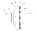
도 1은 본 발명의 일실시예에 따른 탄성 재질의 탄성 공간링을 이용한 내진용 배관 연결장치를 사용하여 배관을 연결한 상태를 나타내는 측면도이다.
도 2는 본 발명의 일실시예에 따른 탄성 재질의 탄성 공간링을 이용한 내진용 배관 연결장치의 한쪽 부분만을 나타내는 분해사시도이다.
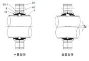
도 3은 본 발명의 일실시예에 따른 탄성 재질의 탄성 공간링을 이용한 내진용 배관 연결장치의 수평 상태와 굴절 상태를 나타내는 조립단면도이다.
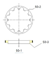
도 4 a, b, c는 본 발명의 다른 실시예에 따른 탄성 재질의 탄성 공간링의 탄성 텍과 내원주부를 나타내는 조립단면도이다.
도 5는 본 발명의 다른 실시예에 따른 탄성 재질의 탄성 공간링을 이용한 내진용 배관 연결장치를 사용하여 건물의 배관을 연결한 상태를 나타내는 측면도이다.
도 6은 본 발명의 다른 실시예에 따른 탄성 재질의 탄성 공간링을 이용한 내진용 배관 연결장치에 있어서, 배관이 경사진 경우 변형된 모습을 나타내는 조립단면도이다.
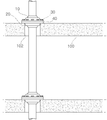
도 7은 본 발명의 다른 실시예에 따른 탄성 재질의 탄성 공간링을 이용한 내진용 배관 연결장치를 사용하여 건물의 배관을 연결한 상태를 나타내는 측면도이다.
도 8은 본 발명의 다른 실시예에 따른 탄성 재질의 탄성 공간링을 이용한 내진용 배관 연결장치를 사용하여 건물의 배관을 연결한 상태에서 지진 등의 발생으로 배관이 경사진 상태를 나타내는 측면도이다.1 is a side view showing a state in which piping is connected using a seismic piping connecting device using an elastic space ring made of an elastic material according to an embodiment of the present invention.
Figure 2 is an exploded perspective view showing only one part of the seismic piping connecting device using an elastic space ring of an elastic material according to an embodiment of the present invention.
3 is an assembly cross-sectional view showing a horizontal state and a refraction state of a seismic pipe connecting device using an elastic space ring made of an elastic material according to an embodiment of the present invention.
4A, B, and C are cross-sectional views showing an elastic tex and an inner circumference of an elastic space ring made of an elastic material according to another embodiment of the present invention.
5 is a side view showing a state in which a pipe of a building is connected using a seismic pipe connecting device using an elastic space ring made of an elastic material according to another embodiment of the present invention.
6 is an assembly cross-sectional view showing a deformed state when the piping is inclined in a seismic piping connecting device using an elastic space ring made of an elastic material according to another embodiment of the present invention.
7 is a side view showing a state in which pipes of a building are connected using a seismic pipe connecting device using an elastic space ring made of an elastic material according to another embodiment of the present invention.
8 is a side view showing a state in which piping is inclined due to an earthquake or the like in a state in which the piping of a building is connected using a seismic piping connecting device using an elastic space ring made of an elastic material according to another embodiment of the present invention.
본 발명을 충분히 이해하기 위해서 본 발명의 바람직한 실시예를 첨부 도면을 참조하여 설명한다. 본 발명의 실시예는 여러 가지 형태로 변형될 수 있으며, 본 발명의 범위가 아래에서 상세히 설명하는 실시예로 한정되는 것으로 해석되어서는 안 된다. 본 실시예는 당업계에서 평균적인 지식을 가진 자에게 본 발명을 보다 완전하게 설명하기 위하여 제공되는 것이다. 따라서 도면에서의 요소의 형상 등은 보다 명확한 설명을 강조하기 위해서 과장되어 표현될 수 있다. 각 도면에서 동일한 부재는 동일한 참조부호로 도시한 경우가 있음을 유의하여야 한다. 또한, 본 발명의 요지를 불필요하게 흐릴 수 있다고 판단되는 공지 기능 및 구성에 대한 상세한 기술은 생략된다.In order to fully understand the present invention, preferred embodiments of the present invention will be described with reference to the accompanying drawings. The embodiments of the present invention may be modified in various forms, and the scope of the present invention should not be interpreted as being limited to the embodiments described in detail below. This embodiment is provided to more fully describe the present invention to those skilled in the art. Accordingly, the shape of the elements in the drawings may be exaggerated to emphasize a clearer description. It should be noted that in each drawing, the same members may be indicated by the same reference numerals. In addition, detailed descriptions of well-known functions and configurations that are judged to unnecessarily obscure the subject matter of the present invention are omitted.
도 2 내지 도 4에 나타낸 바와 같이, 본 발명의 일실시예에 따른 탄성 재질의 탄성 공간링을 이용한 내진용 배관 연결장치는, 파이프(2, 4), 스냅링(8), 제1고정링(10'), 제2고정링(20'), 제1플랜지부재(30'), 제2플랜지부재(40'), 탄성 공간링(50-1), 및 체결부재(70)를 포함하여 이루어진다.2 to 4, the seismic piping connecting device using an elastic space ring made of an elastic material according to an embodiment of the present invention includes a pipe (2, 4), a snap ring (8), and a first fixing ring ( 10 '), a second fixing ring 20', a first flange member 30 ', a second flange member 40', an elastic space ring 50-1, and a fastening
제1고정링(10')은 서로 접하여 설치되는 한쪽 파이프의 끝단 외주면에 결합되고 내주면과 외주면에 오링이 설치되고 외주면이 파이프의 접촉면으로부터 멀어지는 방향으로 갈수록 두께가 얇아지는 경사면인 구면으로 형성되는 합성수지재이다.The first fixing ring 10 'is a synthetic resin formed of a spherical surface that is coupled to the outer circumferential surface of one end of the pipe installed in contact with each other, the O-ring is installed on the inner circumferential surface and the outer circumferential surface, and the outer circumferential surface becomes thinner in thickness in the direction away from the contact surface of the pipe. It is ash.
제2고정링(20')은 서로 접하여 설치되는 다른쪽 파이프의 끝단 외주면에 결합되고 내주면과 외주면에 오링이 설치되고 외주면이 파이프의 접촉면으로부터 멀어지는 방향으로 갈수록 두께가 얇아지는 경사면인 구면으로 형성되고 상기 제1고정링과 측면이 밀착되는 상태로 설치되는 합성수지재이다.The second fixing ring 20 'is coupled to the outer circumferential surface of the other end of the pipe that is installed in contact with each other, the O-ring is installed on the inner circumferential surface and the outer circumferential surface, and the outer circumferential surface is formed of a spherical surface which is an inclined surface that becomes thinner in thickness in a direction away from the contact surface of the pipe. It is a synthetic resin material that is installed in close contact with the first fixing ring.
제1플랜지부재(30')는 상기 제1고정링(10')의 외주면에 결합되고 둘레를 따라 간격을 두고 복수의 체결구멍이 형성되고 내주면은 상기 제1고정링의 외주면에 대응하는 경사면인 구면으로 형성되는 금속재질이다.The first flange member 30 'is coupled to the outer circumferential surface of the first fixing ring 10', a plurality of fastening holes are formed at intervals along the circumference, and the inner circumferential surface is an inclined surface corresponding to the outer circumferential surface of the first fixing ring It is a metal material formed into a spherical surface.
제2플랜지부재(40')는 상기 제2고정링(20')의 외주면에 결합되고 둘레를 따라 간격을 두고 복수의 체결구멍이 형성되고 상기 제1플랜지부재와 접한 상태로 설치되고 내주면은 상기 제2고정링(20')의 외주면에 대응하는 경사면인 구면으로 형성되는 금속재질이다.The second flange member 40 'is coupled to the outer circumferential surface of the second fixing ring 20', a plurality of fastening holes are formed at intervals along the circumference, and installed in contact with the first flange member, and the inner circumferential surface is the It is a metal material formed of a spherical surface that is an inclined surface corresponding to the outer peripheral surface of the second fixing ring 20 '.
탄성 공간링(50-1)은 상기 제1고정링(10')과 제2고정링(20')의 서로 마주하여 위치하는 측면에 끼워지는 탄성재질이다.The elastic space ring 50-1 is an elastic material that is fitted to the side surfaces of the first fixing ring 10 'and the second fixing ring 20' that face each other.
상기 탄성 공간링(50-1)이 두께 방향으로 수축하면 제1고정링(10')과 제2고정링(20') 사이도 안정적으로 실링할 수 있는 탄성 변형 가능한 소재를 사용하는 것이 바람직하다.When the elastic space ring 50-1 contracts in the thickness direction, it is preferable to use an elastically deformable material that can stably seal between the first fixing ring 10 'and the second fixing ring 20'. .
상기 탄성 공간링(50-1)의 내측에 탄성 텍(50-3)을 주어 파이프 내경에 맞춰 위치 고정할 수 있다. 즉 상기 탄성 공간링(50-1)의 한측에만 탄성 텍(50-3)을 설치하여도 상기 파이프 내경에 맞추면서 고정할 수 있기 때문이다.An elastic tex (50-3) is provided inside the elastic space ring (50-1) to fix the position according to the pipe inner diameter. That is, even if the elastic tex 50-3 is installed on only one side of the elastic space ring 50-1, it is possible to fix it while matching the inner diameter of the pipe.
설치 방법으로는 양쪽 파이프(2, 4)를 서로 맞닿는 상태로 위치시키고, 제2고정링(20')의 측면에 상기 탄성부재(50)의 측면이 접촉되며 탄성 텍(50-3)이 상기 파이프 내경에 삽입시된 상태로 상기 제1고정링(10')을 밀착되는 상태로 위치시킨다.As the installation method, both
상기 탄성 공간링(50-1)의 내부 공간부의 내원주부(50-2)는 수직 절단면의 평면이 반원형이다.The inner circumferential portion 50-2 of the inner space portion of the elastic space ring 50-1 has a semi-circular plane of a vertical cut surface.
따라서 상기 제1고정링(10')과 제2고정링(20')이 변형되면서 파이프(2, 4) 사이에 발생하는 변형을 흡수하는 것이 가능하고, 이 경우에 발생하는 틈새를 효과적으로 밀폐되는 상태로 유지할 수 있다.Accordingly, it is possible to absorb the deformation occurring between the
또한 본 발명은 내원주부(50-2)가 그냥 곡선으로만 이루어진 경우 보다 신축성을 보완하고 지속적인 내구성을 보강하여 장시간 사용 가능하다.In addition, the present invention can be used for a long time by supplementing the elasticity and reinforcing the continuous durability than when the inner circumferential portion 50-2 is made only of a curved line.
서로 접하여 설치되는 양쪽 파이프(2, 4)의 끝부분 외주면에는 고정홈(3)을 형성하고, 상기 파이프(2, 4)의 고정홈에는 스냅링(8)을 삽입하여 설치하고, 상기 제1고정링(10)과 제2고정링(20)의 서로 접하는 측면의 내주면쪽 모서리에는 상기 스냅링의 일부가 삽입되는 걸림턱을 형성한다.Fixing grooves 3 are formed on the outer circumferential surfaces of the ends of the
상기 제1고정링(10)과 제2고정링(20)의 서로 마주하여 위치하는 측면에는 각각 복수의 탄성부재구멍(28)을 형성하고,A plurality of
상기 제1고정링(10)의 탄성부재구멍(28)과 상기 제2고정링(20)의 탄성부재구멍에 삽입되는 상태로 복수의 탄성부재를 설치한다.A plurality of elastic members are installed while being inserted into the
최종적으로 본 발명은 상기 제1플랜지부재와 제2플랜지부재를 서로 일체로 체결하여 고정하는 복수의 체결부재(70)를 포함한다.Finally, the present invention includes a plurality of
한편 도 5와 도 6에 나타낸 바와 같이, 본 발명의 일실시예에 따른 탄성 재질의 탄성 공간링을 이용한 내진용 배관 연결장치는 제1고정링(10)과, 제2고정링(20)과, 제1플랜지부재(30)와, 제2플랜지부재(40)와, 체결부재(70)를 포함하여 이루어진다.On the other hand, as shown in Figures 5 and 6, seismic piping connecting device using an elastic space ring of an elastic material according to an embodiment of the present invention, the
상기 제1고정링(10)은 서로 접하여 설치되는 한쪽 파이프(2)의 끝단 외주면에 결합되어 설치된다.The
상기 제2고정링(20)은 서로 접하여 설치되는 다른쪽 파이프(4)의 끝단 외주면에 결합되어 설치된다.The
상기 제1고정링(10)과 제2고정링(20)의 내주면과 외주면(11, 21)에는 오링(60)이 설치된다.O-
상기 제1고정링(10)과 제2고정링(20)의 외주면(11, 21)에는 오링(60)이 삽입되는 링홈(13, 23)이 형성된다.Ring grooves 13 and 23 into which the O-
상기 제1고정링(10)과 제2고정링(20)의 내주면에도 오링(60)이 삽입되는 링홈(14, 24)이 형성된다.Ring grooves 14 and 24 into which the O-
상기 제1고정링(10)과 제2고정링(20)은 외주면(11, 21)이 이웃하는 파이프(2, 4)의 접촉면으로부터 멀어지는 방향으로 갈수록 두께가 얇아지는 경사면으로 형성한다.The
상기에서 제1고정링(10)과 제2고정링(20)의 외주면(11, 21)은 곡면(예를 들면, 구면의 일부)으로 형성하는 것이 상기 제1플랜지부재(30) 및 제2플랜지부재(40)와 구면접촉이 이루어지므로 바람직하다.In the above, the outer peripheral surfaces 11 and 21 of the
상기 제1고정링(10)과 제2고정링(20)은 합성수지나 실리콘 등의 재질로 형성하는 것이 이웃하여 연결되는 파이프(2, 4)가 지진 등이 발생하여 서로 어긋나는 방향으로 경사져 연결부위에 변형이 발생하는 경우에 상기 제1고정링(10)과 제2고정링(20)이 변형되면서 파이프(2, 4) 사이에 발생하는 변형을 흡수하는 것이 가능하고, 이 경우에 발생하는 틈새를 효과적으로 밀폐되는 상태로 유지하는 것이 가능하므로 바람직하다.The
상기 제1고정링(10)과 제2고정링(20)의 서로 마주하여 위치하는 측면에는 각각 복수의 탄성부재구멍(18, 28)을 형성하고, 상기 제1고정링(10)의 탄성부재구멍(18)과 상기 제2고정링(20)의 탄성부재구멍(28)에 삽입되는 상태로 복수의 탄성부재(50)을 설치하는 것도 가능하다.A plurality of elastic member holes 18 and 28 are respectively formed on the side surfaces of the
상기와 같이 제1고정링(10)과 제2고정링(20) 사이에 탄성부재(50)을 설치하면, 제1고정링(10)과 제2고정링(20) 사이에 변형이 발생하는 경우에 복원력을 부여하는 것이 가능하다.When the
또는, 상기 파이프(2, 4)를 서로 결합시킨 상태에서 유체가 내부에 없는 경우에는 상기 제1고정링(10)과 제2고정링(20)이 중심부로 밀리면서 오링(60)이 상기 제2플랜지부재(30)와 제2플랜지부재(40)에 밀착되지 않아 유체가 누설될 수 있지만, 상기와 같이 제1고정링(10)과 제2고정링(20) 사이에 탄성부재(50)을 설치하면, 상기 탄성부재(50)의 탄성력이 작용하여 상기 제1고정링(10)과 제2고정링(20)이 상기 제1플랜지부재(30)와 제2플랜지부재(40)에 밀착되어 유체가 누설되는 것을 방지하는 것이 가능하다.Or, when the fluid is not inside in a state where the
상기 제1플랜지부재(30)는 상기 제1고정링(10)의 외주면에 결합되는 상태로 설치된다.The
상기 제2플랜지부재(40)는 상기 제2고정링(20)의 외주면에 결합되는 상태로 설치된다.The
상기 제1플랜지부재(30)와 제2플랜지부재(40)에는 둘레를 따라 간격을 두고 복수의 체결구멍(36, 46)이 형성된다.A plurality of fastening holes 36 and 46 are formed at intervals along the circumference of the
상기 제2플랜지부재(40)는 상기 제1플랜지부재(30)와 서로 접하는 상태로 설치된다.The
상기 제1플랜지부재(30)와 제2플랜지부재(40)는 금속재로 형성하는 것이 구조적인 강도를 높게 유지하는 것이 가능하므로 바람직하다.The
상기 제1플랜지부재(30)와 제2플랜지부재(40)는 상기 체결구멍(36, 46)을 관통하여 설치되는 체결부재(70)에 의하여 서로 밀착된 상태로 일체로 고정된다.The
상기 체결부재(70)는 볼트를 이용하여 구성하는 것도 가능하며, 볼트와 체결되는 너트(72)를 추가적으로 사용하는 것도 가능하다.The
도 4 a, b, c에 나타난 바와 같이, 탄성 공간링(50-1)이 물이 유입되기 전 탄성력으로 제1고정링(10)과 제2고정링(20)을 밀어 내어, 초기에서 수압이 걸리기 전까지 기밀을 유지해 준다.As shown in Figures 4 a, b, c, the elastic space ring (50-1) pushes the first fixing ring (10) and the second fixing ring (20) with elastic force before water flows in, and the hydraulic pressure in the initial stage Keep it confidential until it gets caught.
물이 유입되면 수압에 의해 내원주부(50-2)의 공간으로 물이 유입되어, 제1플랜지부재(30)와 제1고정링(10) 사이의 기밀을 유지시키면서 굴절되는 방향으로 폭이 축소되고 반대편은 팽창되어도 효과적으로 밀착되는 상태를 유지할 수 있다.When water flows in, water flows into the space of the inner circumferential portion 50-2 by water pressure, and the width decreases in the direction of refraction while maintaining airtightness between the
탄성 텍(50-3)은 파이프(2, 4)의 내경에 중심을 잡아주어 탄성 공간링(50-1)이 밀리지 않도록 하는 역할을 한다.The elastic tex 50-3 serves to prevent the elastic space ring 50-1 from being pushed by holding the center of the inner diameters of the
또한 탄성 공간링(50-1)의 탄성력을 이용하여 굴절되는 방향으로는 폭이 축소되고, 반대편은 팽창되도록 하는 역할을 한다.In addition, the width is reduced in the direction of refraction using the elastic force of the elastic space ring 50-1, and the other side serves to expand.
그리고, 도 5에 나타낸 바와 같이, 상기에서 체결부재(70)를 볼트를 사용하는 경우, 상기 제2플랜지부재(40)에 형성되는 체결구멍(46)의 내면에 암나사(47)를 형성하면, 너트(72)를 사용하지 않고도 체결부재(70)를 체결하여 고정하는 것이 가능하다.And, as shown in Figure 5, when using a bolt for the
상기 제1플랜지부재(30)와 제2플랜지부재(40)의 내주면(32, 42)은 상기 제1고정링(10)과 제2고정링(20)의 외주면(11, 21)에 대응하는 경사면으로 형성한다.The inner circumferential surfaces 32 and 42 of the
상기에서 제1고정링(10)과 제2고정링(20)의 외주면(11, 21)을 곡면(예를 들면, 구면의 일부)으로 형성하고, 상기 제1플랜지부재(30)와 제2플랜지부재(40)의 내주면(32, 42)을 대응하는 곡면으로 형성하면, 상기 제1고정링(10) 및 제2고정링(20)의 외주면(11, 21)과 상기 제1플랜지부재(30) 및 제2플랜지부재(40)의 내주면(32, 42) 사이에 구면접촉이 이루어지며, 파이프(2, 4)가 서로 어긋나게 경사질 때에 상기 제1고정링(10)과 제2고정링(20)이 파이프(2, 4)의 경사에 대응하여 변형되는 것이 용이하게 이루어진다.In the above, the outer peripheral surfaces 11 and 21 of the
상기 제1플랜지부재(30)와 제2플랜지부재(40)의 외주면을 상기 제1고정링(10)과 제2고정링(20)의 외주면(11, 21)에 대응하는 곡면(예를 들면, 구면의 일부)으로 형성하는 것도 가능하다.The outer circumferential surfaces of the
그리고, 상기 제2플랜지부재(40)의 상기 제1플랜지부재(30)와 접하는 측면(44)에는 링홈(45)을 형성하고, 상기 링홈(45)에는 오링(60)을 설치하는 것도 가능하다.In addition, a ring groove 45 is formed on a side surface 44 of the
상기와 같이 제2플랜지부재(40)의 측면(44)에 오링(60)을 설치하면, 상기 제1플랜지부재(30)와 제2플랜지부재(40) 사이의 결합면의 밀폐성이 크게 향상된다.When the O-
그리고, 상기에서 서로 접하여 설치되는 양쪽 파이프(2, 4)의 끝부분 외주면에는 둘레를 따라 고정홈(3, 5)을 형성하고, 상기 고정홈(3, 5)에는 스냅링(8)을 삽입하여 설치하는 것도 가능하다.And, in the outer peripheral surface of the ends of both pipes (2, 4) installed in contact with each other in the form of fixing grooves (3, 5) along the circumference, and inserting snap rings (8) into the fixing grooves (3, 5) It is also possible to install.
상기 고정홈(3, 5)은 삽입된 상기 스냅링(8)의 일부가 파이프(2, 4)의 외주면보다 돌출되는 깊이로 형성한다.The fixing groove (3, 5) is formed to a depth that a part of the inserted snap ring (8) protrudes than the outer peripheral surface of the pipe (2, 4).
상기 제1고정링(10)과 제2고정링(20)의 서로 접하는 측면(12, 22)의 내주면쪽 모서리에는 상기 스냅링(8)의 일부가 삽입되는 걸림턱(15, 25)을 형성하는 것도 가능하다.At the inner circumferential edge of the side 12 and 22 of the
상기와 같이 스냅링(8)을 설치하고 걸림턱(15, 25)을 형성하면, 파이프(2, 4)의 끝단에 결합된 상기 제1고정링(10)과 제2고정링(20)이 파이프(2, 4)로부터 이탈되는 것이 방지된다.When the
다음으로 상기와 같이 구성되는 본 발명의 일실시예에 따른 탄성 재질의 탄성 공간링을 이용한 내진용 배관 연결장치를 사용하여 파이프를 서로 연결하는 과정을 설명한다.Next, a process of connecting pipes to each other using a seismic pipe connecting device using an elastic space ring made of an elastic material according to an embodiment of the present invention configured as described above will be described.
먼저, 파이프(2, 4)의 끝단에 고정홈(3, 5)을 형성한다.First, fixing grooves 3 and 5 are formed at the ends of the
그리고, 상기 제1고정링(10)의 외주면(11)에 형성된 링홈(13)과 내주면에 현성된 링홈(14)에 각각 오링(60)을 삽입하고, 상기 제2고정링(20)의 외주면(21)에 형성된 링홈(23)과 내주면에 현성된 링홈(24)에 각각 오링(60)을 삽입한다.Then, the O-
또, 상기 제2플랜지부재(40)의 측면(44)에 형성된 링홈(45)에도 오링(60)을 삽입한다.In addition, the O-
그리고, 한쪽 파이프(2)에는 제1플랜지부재(30)와 제1고정링(10)을 순차적으로 삽입하고, 다른쪽 파이프(4)에는 제2플랜지부재(40)와 제2고정링(20)을 순차적으로 삽입한다.Then, the
다음으로, 파이프(2, 4)의 고정홈(3, 5)에 스냅링(8)을 각각 결합한다.Next, the snap rings 8 are coupled to the fixing grooves 3 and 5 of the
그리고, 상기 제1고정링(10)의 탄성부재구멍(18)에 탄성부재(50)을 삽입한 다음, 상기 제1고정링(10)과 제2고정링(20)을 양쪽 파이프(2, 4)의 끝단까지 이동시키고, 양쪽 파이프(2, 4)를 서로 맞닿는 상태로 위치시키고, 상기 제2고정링(20)의 탄성부재구멍(28)에 상기 탄성부재(50)의 반대쪽이 삽입되는 상태로 상기 제1고정링(10)과 상기 제2고정링(20)을 밀착되는 상태로 위치시킨다.Then, after inserting the
상기에서 양쪽 파이프(2, 4)의 서로 마주하는 끝단은 완전 밀착되는 상태가 아니고, 약간의 간격(예를 들면, 10mm 정도)을 두고 위치하도록 구성하는 것이 파이프(2, 4)가 서로 어긋나는 방향으로 경사질 수 있는 최소한의 공간(파이프끼리 간섭을 줄일 수 있는 공간)을 확보할 수 있으므로 바람직하다.In the above, the ends of the
그리고, 상기 제1고정링(10)과 제2고정링(20)의 서로 마주하는 끝면도 상기 양쪽 파이프(2, 4)와 마찬가지로 약간의 간격을 두고 위치하도록 구성하는 것도 가능하다.In addition, the end faces of the
또, 상기 제1플랜지부재(30)와 제2플랜지부재(40)를 이동시켜 서로 맞닿게 하고, 체결부재(70)를 이용하여 제1플랜지부재(30)와 제2플랜지부재(40)를 서로 완전히 밀착된 상태로 체결 고정한다.In addition, the
상기와 같이 구성하면, 상기 제1플린재부재(30)와 제2플랜지부재(40) 사이, 상기 제1플랜지부재(30)와 제1고정링(10)의 사이, 상기 제2플랜지부재(40)와 제2고정링(20)의 사이, 상기 제1고정링(10)과 한쪽 파이프(2)의 사이, 상기 제2고정링(20)과 다른쪽 파이프(4)의 사이에 각각 오링(60)이 설치되어 있으므로, 기밀성이 높게 유지된다.When configured as described above, between the
도 7에는 상기와 같이 양쪽 파이프(2, 4)를 연결한 구성을 건물(100)에 설치한 상태를 나타낸다.7 shows a state in which a structure in which both
도 7에 나타낸 바와 같이, 본 발명의 다른 실시예에 따른 탄성 재질의 탄성 공간링을 이용한 내진용 배관 연결장치를 사용하면, 파이프(2, 4)를 배관하기 위하여 건물의 벽체(100)에 형성된 배관구멍(102)과 파이프(2, 4) 사이의 틈새를 곡면(예를 들면, 구면의 일부)으로 형성되는 상기 제1고정링(10) 또는 제2고정링(20)의 외주면(11, 21)이나 상기 제1플랜지부재(30) 또는 제2플랜지부재(40)의 외주면으로 폐쇄하는 것이 가능하므로, 별도의 불연재나 시멘트 등의 채움재를 이용하여 충진할 필요가 없고, 배관 설치작업을 보다 용이하게 수행하는 것이 가능하다.As shown in FIG. 7, when using a seismic piping connecting device using an elastic space ring made of an elastic material according to another embodiment of the present invention, it is formed on a
도 8 에는 지진 등이 발생하여 이웃하여 연결되는 파이프(2, 4)가 서로 어긋나는 방향으로 경사지는 경우에 상기 제1고정링(10)과 제2고정링(20)이 변형되는 상태를 나타낸다.8 shows a state in which the
예를 들면, 한쪽 파이프(2)와 다른쪽 파이프(4)에 서로 다른 방향의 외력이 작용하여 양쪽 파이프(2, 4)가 서로 어긋나는 방향으로 경사지게 되면, 양쪽 파이프(2, 4)의 서로 맞닿는 끝면은 한쪽은 붙고 반대쪽은 벌어지는 형상으로 변형되고, 상기 제1고정링(10)과 제2고정링(20)은 상기 파이프(2, 4)에 설치된 스냅링(8)에 걸림턱(15, 25)이 걸린 상태이므로 상기 파이프(2, 4)와 같은 형상으로 변형되는 반면에, 상기 제1플랜지부재(30)와 제2플랜지부재(40)는 체결부재(70)에 의하여 서로 밀착되어 고정된 상태가 유지된다.For example, when an external force in different directions acts on one
상기에서 제1고정링(10)과 제2고정링(20)의 외주면(11, 21)을 곡면으로 형성하고, 상기 제1플랜지부재(30)와 제2플랜지부재(40)의 내주면(32, 42)을 대응하는 곡면으로 형성하므로, 상기 제1고정링(10) 및 제2고정링(20)의 외주면(11, 21)과 상기 제1플랜지부재(30) 및 제2플랜지부재(40)의 내주면(32, 42) 사이에 구면접촉이 이루어져 상기 제1플랜지부재(30)와 제2플랜지부재(40)의 위치가 일정하게 고정된 상태에서 상기 제1고정링(10)과 제2고정링(20)은 상기 제1플랜지부재(30)와 제2플랜지부재(40)와의 사이에 미끄럼 이동이 가능한 상태로 결합된다.In the above, the outer circumferential surfaces 11 and 21 of the
따라서, 양쪽 파이프(2, 4)가 서로 어긋나게 경사질 때에 상기 제1고정링(10)과 제2고정링(20)이 파이프(2, 4)와 함께 변형되는 것이 가능하다.Therefore, it is possible for the
상기와 같이 이루어지는 본 발명에 따른 탄성 재질의 탄성 공간링을 이용한 내진용 배관 연결장치에 의하면, 유체의 누설을 방지하면서 양쪽 파이프(2, 4)가 내진규정에 규정된 경사각(7ㅀ) 이상으로 서로 어긋나는 방향으로 경사지도록 연결하는 것이 가능하다.According to the seismic piping connecting device using the elastic space ring made of an elastic material according to the present invention made as described above, both
2 - 한쪽 파이프, 3 - 고정홈, 4 - 다른쪽 파이프, 5 - 고정홈, 8 - 스냅링
10 - 제1고정링, 11 - 제1고정링의 외주면, 12 - 제1고정링의 측면
13,14 - 링홈, 15 - 걸림턱, 18 - 탄성부재구멍, 20 - 제2고정링
21 - 제2고정링의 외주면, 22 - 제2고정링의 측면, 23, 24 - 링홈
25 - 걸림턱, 28 - 탄성부재구멍, 30 - 제1플랜지부재
32 - 제1플랜지부재의 내주면, 36 - 체결구멍, 40 - 제2플랜지부재
42 - 제2플랜지부재의 내주면, 44 - 제2플랜지부재의 측면, 45 - 링홈
46 - 체결구멍, 47 - 암나사, 50 - 탄성부재, 50-1 : 탄성 공간링
50-2 : 내원주부, 50-3 : 탄성 텍, 60 - 오링, 70 - 체결부재
72 - 너트, 100 - 건물의 벽체, 102 - 배관구멍2-one pipe, 3-fixing groove, 4-other pipe, 5-fixing groove, 8-snap ring
10-first fixing ring, 11-outer peripheral surface of the first fixing ring, 12-side of the first fixing ring
13,14-ring groove, 15-locking jaw, 18-elastic member hole, 20-second fixing ring
21-Outer peripheral surface of the second fixing ring, 22-Side of the second fixing ring, 23, 24-Ring groove
25-locking jaw, 28-elastic member hole, 30-first flange member
32-inner peripheral surface of the first flange member, 36-fastening hole, 40-second flange member
42-inner peripheral surface of the second flange member, 44-side surface of the second flange member, 45-ring groove
46-fastening hole, 47-female thread, 50-elastic member, 50-1: elastic space ring
50-2: inner circumference, 50-3: elastic tex, 60-O-ring, 70-fastening member
72-nut, 100-building wall, 102-plumbing hole
Claims (5)
서로 접하여 설치되는 다른쪽 파이프의 끝단 외주면에 결합되고 내주면과 외주면에 오링이 설치되고 외주면이 파이프의 접촉면으로부터 멀어지는 방향으로 갈수록 두께가 얇아지는 경사면인 구면으로 형성되고 상기 제1고정링과 측면이 밀착되는 상태로 설치되는 합성수지재의 제2고정링;
상기 제1고정링의 외주면에 결합되고 둘레를 따라 간격을 두고 복수의 체결구멍이 형성되고 내주면은 상기 제1고정링의 외주면에 대응하는 경사면인 구면으로 형성되는 금속재의 제1플랜지부재;
상기 제2고정링의 외주면에 결합되고 둘레를 따라 간격을 두고 복수의 체결구멍이 형성되고 상기 제1플랜지부재와 접한 상태로 설치되고 내주면은 상기 제2고정링의 외주면에 대응하는 경사면인 구면으로 형성되는 금속재의 제2플랜지부재;
상기 제1고정링과 제2고정링의 서로 마주하여 위치하는 측면에 끼워지는 탄성 공간링;
상기 제1플랜지부재와 제2플랜지부재를 서로 일체로 체결하여 고정하는 복수의 체결부재를 포함하는 탄성 재질의 탄성 공간링을 이용한 내진용 배관 연결장치.A first fixing ring of a synthetic resin material which is coupled to the outer circumferential surface of one end of the pipe installed in contact with each other, and has an O-ring installed on the inner circumferential surface and an outer circumferential surface, and is formed with a spherical surface which is an inclined surface whose thickness becomes thinner in a direction away from the contact surface of the pipe;
It is coupled to the outer circumferential surface of the ends of the other pipes installed in contact with each other, O-rings are installed on the inner circumferential surface and the outer circumferential surface, and the outer circumferential surface is formed into a spherical surface that is an inclined surface that becomes thinner in thickness in a direction away from the contact surface of the pipe. A second fixing ring of a synthetic resin material installed in a state of being;
A first flange member of a metal material which is coupled to the outer circumferential surface of the first fixing ring, is formed with a plurality of fastening holes at intervals along the circumference, and the inner circumferential surface is a spherical surface that is an inclined surface corresponding to the outer circumferential surface of the first fixing ring;
It is coupled to the outer circumferential surface of the second fixing ring, a plurality of fastening holes are formed at intervals along the circumference, and is installed in contact with the first flange member, and the inner circumferential surface is a spherical surface that is an inclined surface corresponding to the outer circumferential surface of the second fixing ring. A second flange member made of a metal material;
An elastic space ring fitted on a side surface of the first fixing ring and the second fixing ring facing each other;
Seismic piping connection device using an elastic space ring made of an elastic material, including a plurality of fastening members for fastening the first and second flange members integrally with each other.
상기 탄성 공간링의 내측에 탄성 텍을 주어 파이프 내경에 맞춰 위치 고정할 수 있는 것을 특징으로 하는 탄성 재질의 탄성 공간링을 이용한 내진용 배관 연결장치.According to claim 1,
Seismic piping connection device using an elastic space ring made of an elastic material, characterized in that the elastic space ring can be fixed to the inside diameter of a pipe by giving an elastic tex on the inside of the elastic space ring.
상기 탄성 공간링의 내부 공간부의 내원주부는 수직 절단면의 평면이 반원형인 것을 특징으로 하는 탄성 재질의 탄성 공간링을 이용한 내진용 배관 연결장치.According to claim 1,
The inner circumferential portion of the inner space portion of the elastic space ring is seismic piping connection device using an elastic space ring made of elastic material, characterized in that the plane of the vertical cut surface is semi-circular.
서로 접하여 설치되는 양쪽 파이프의 끝부분 외주면에는 고정홈을 형성하고,
상기 파이프의 고정홈에는 스냅링을 삽입하여 설치하고,
상기 제1고정링과 제2고정링의 서로 접하는 측면의 내주면쪽 모서리에는 상기 스냅링의 일부가 삽입되는 걸림턱을 형성하는 탄성 재질의 탄성 공간링을 이용한 내진용 배관 연결장치.According to claim 1,
Fixing grooves are formed on the outer circumferential surfaces of the ends of the pipes installed in contact with each other.
Install the snap ring by inserting it into the fixing groove of the pipe,
A seismic piping connection device using an elastic space ring made of an elastic material forming a locking jaw into which a portion of the snap ring is inserted at an edge of an inner circumferential surface of a side contacting each other of the first and second fixing rings.
상기 제1고정링과 제2고정링의 서로 마주하여 위치하는 측면에는 각각 복수의 탄성부재구멍을 형성하고,
상기 제1고정링의 탄성부재구멍과 상기 제2고정링의 탄성부재구멍에 삽입되는 상태로 복수의 탄성부재를 설치하는 탄성 재질의 탄성 공간링을 이용한 내진용 배관 연결장치.According to claim 1,
A plurality of elastic member holes are respectively formed on the side surfaces of the first fixing ring and the second fixing ring facing each other,
Seismic piping connection device using an elastic space ring made of an elastic material to install a plurality of elastic members in a state that is inserted into the elastic member hole of the first fixing ring and the elastic member hole of the second fixing ring.
Priority Applications (2)
| Application Number | Priority Date | Filing Date | Title |
|---|---|---|---|
| KR1020180107591A KR20200029162A (en) | 2018-09-10 | 2018-09-10 | Pipe Connecting Device for Earthquake-Proof using Elastic space ring |
| PCT/KR2018/012378 WO2020054902A1 (en) | 2018-09-10 | 2018-10-19 | Earthquake-resistant pipe connecting device using elastic space ring of elastic material |
Applications Claiming Priority (1)
| Application Number | Priority Date | Filing Date | Title |
|---|---|---|---|
| KR1020180107591A KR20200029162A (en) | 2018-09-10 | 2018-09-10 | Pipe Connecting Device for Earthquake-Proof using Elastic space ring |
Related Child Applications (1)
| Application Number | Title | Priority Date | Filing Date |
|---|---|---|---|
| KR1020200071639A Division KR102177099B1 (en) | 2020-06-12 | 2020-06-12 | Pipe Connecting Device for Earthquake-Proof using Elastic space ring |
Publications (1)
| Publication Number | Publication Date |
|---|---|
| KR20200029162A true KR20200029162A (en) | 2020-03-18 |
Family
ID=69777891
Family Applications (1)
| Application Number | Title | Priority Date | Filing Date |
|---|---|---|---|
| KR1020180107591A Ceased KR20200029162A (en) | 2018-09-10 | 2018-09-10 | Pipe Connecting Device for Earthquake-Proof using Elastic space ring |
Country Status (2)
| Country | Link |
|---|---|
| KR (1) | KR20200029162A (en) |
| WO (1) | WO2020054902A1 (en) |
Cited By (1)
| Publication number | Priority date | Publication date | Assignee | Title |
|---|---|---|---|---|
| CN113418051A (en) * | 2021-05-11 | 2021-09-21 | 宛梦园 | Three-way pipe |
Families Citing this family (1)
| Publication number | Priority date | Publication date | Assignee | Title |
|---|---|---|---|---|
| CN119554505B (en) * | 2025-02-05 | 2025-04-15 | 辽宁维航基业科技有限公司 | An oil delivery hose with a leakage alarm device |
Citations (2)
| Publication number | Priority date | Publication date | Assignee | Title |
|---|---|---|---|---|
| US380765A (en) | 1888-04-10 | pendleton | ||
| JP2010165369A (en) | 2001-09-25 | 2010-07-29 | Apple Inc | Japanese virtual dictionary |
Family Cites Families (5)
| Publication number | Priority date | Publication date | Assignee | Title |
|---|---|---|---|---|
| JP2001165369A (en) * | 1999-12-07 | 2001-06-22 | Toozen Sangyo Kk | Universal pipe joint |
| KR100917120B1 (en) * | 2007-08-21 | 2009-09-11 | 박내열 | Coupler for Pipe |
| KR101304551B1 (en) * | 2012-12-03 | 2013-09-05 | (주)한국피엔에스 | Pipe connecting device |
| KR101656219B1 (en) * | 2015-12-17 | 2016-09-13 | 대림프라스틱 주식회사 | Seamed pipe device for forming a dual fixed for sewer pipe connection |
| KR101837504B1 (en) * | 2016-11-18 | 2018-03-14 | 주식회사 보람 | Coupler for the water supply or drain pipe |
-
2018
- 2018-09-10 KR KR1020180107591A patent/KR20200029162A/en not_active Ceased
- 2018-10-19 WO PCT/KR2018/012378 patent/WO2020054902A1/en not_active Ceased
Patent Citations (2)
| Publication number | Priority date | Publication date | Assignee | Title |
|---|---|---|---|---|
| US380765A (en) | 1888-04-10 | pendleton | ||
| JP2010165369A (en) | 2001-09-25 | 2010-07-29 | Apple Inc | Japanese virtual dictionary |
Non-Patent Citations (1)
| Title |
|---|
| 독일 특허공보 DE30391 |
Cited By (1)
| Publication number | Priority date | Publication date | Assignee | Title |
|---|---|---|---|---|
| CN113418051A (en) * | 2021-05-11 | 2021-09-21 | 宛梦园 | Three-way pipe |
Also Published As
| Publication number | Publication date |
|---|---|
| WO2020054902A1 (en) | 2020-03-19 |
Similar Documents
| Publication | Publication Date | Title |
|---|---|---|
| RU2449199C2 (en) | Threaded connection with self sealing | |
| JP5346067B2 (en) | A system for dynamically sealing a conduit sleeve into which a pipe or cable is inserted | |
| KR101754397B1 (en) | Grooveless coupling | |
| KR101330452B1 (en) | Flange for coupling plumbing | |
| KR101922419B1 (en) | Pipe Connecting Device for Earthquake-Proof | |
| KR101916892B1 (en) | Fast groove joint | |
| JPH02107886A (en) | Connecot for smooth pipe receiving pressure fluid | |
| KR101318774B1 (en) | Ball type expansion joint | |
| KR101290291B1 (en) | Drain pipe joint structure having slip joint for cope with work in place | |
| KR20200029162A (en) | Pipe Connecting Device for Earthquake-Proof using Elastic space ring | |
| KR102053283B1 (en) | Pipe coupler | |
| KR101488337B1 (en) | Coupling | |
| KR102623297B1 (en) | Composite pipe joint coupling | |
| KR102177099B1 (en) | Pipe Connecting Device for Earthquake-Proof using Elastic space ring | |
| JP2001330185A (en) | Seismic joints and pipelines | |
| KR101666651B1 (en) | Pipe connecting device of the anti-vortex and earthquake-resistant construction | |
| KR20190016641A (en) | Flange structure for water supply pipe | |
| JP7326524B2 (en) | Separation prevention structure for pipe connections | |
| KR101573346B1 (en) | Separation Prevention for Pipe | |
| KR20170129573A (en) | Coupling Structure for Pipes | |
| JP7324034B2 (en) | Seismic repair valve | |
| KR100657227B1 (en) | Cylindrical Expansion Joint | |
| KR101455339B1 (en) | Pipe connector assembly | |
| KR101632224B1 (en) | Connecting band for upper and drain pipe in structure | |
| JP2023138491A (en) | Vertical pipe fitting |
Legal Events
| Date | Code | Title | Description |
|---|---|---|---|
| A201 | Request for examination | ||
| PA0109 | Patent application |
Patent event code: PA01091R01D Comment text: Patent Application Patent event date: 20180910 |
|
| PA0201 | Request for examination | ||
| E902 | Notification of reason for refusal | ||
| PE0902 | Notice of grounds for rejection |
Comment text: Notification of reason for refusal Patent event date: 20200129 Patent event code: PE09021S01D |
|
| PG1501 | Laying open of application | ||
| E601 | Decision to refuse application | ||
| PE0601 | Decision on rejection of patent |
Patent event date: 20200417 Comment text: Decision to Refuse Application Patent event code: PE06012S01D Patent event date: 20200129 Comment text: Notification of reason for refusal Patent event code: PE06011S01I |
|
| A107 | Divisional application of patent | ||
| PA0107 | Divisional application |
Comment text: Divisional Application of Patent Patent event date: 20200612 Patent event code: PA01071R01D |