KR20200029537A - 환기식 병 및 이를 위한 토출 헤드를 갖는 액체 분배기 - Google Patents
환기식 병 및 이를 위한 토출 헤드를 갖는 액체 분배기 Download PDFInfo
- Publication number
- KR20200029537A KR20200029537A KR1020207004176A KR20207004176A KR20200029537A KR 20200029537 A KR20200029537 A KR 20200029537A KR 1020207004176 A KR1020207004176 A KR 1020207004176A KR 20207004176 A KR20207004176 A KR 20207004176A KR 20200029537 A KR20200029537 A KR 20200029537A
- Authority
- KR
- South Korea
- Prior art keywords
- liquid
- discharge head
- liquid reservoir
- ventilation hole
- ventilation
- Prior art date
- Legal status (The legal status is an assumption and is not a legal conclusion. Google has not performed a legal analysis and makes no representation as to the accuracy of the status listed.)
- Ceased
Links
- 239000007788 liquid Substances 0.000 title claims abstract description 165
- 238000009423 ventilation Methods 0.000 claims abstract description 138
- 230000008878 coupling Effects 0.000 claims abstract description 9
- 238000010168 coupling process Methods 0.000 claims abstract description 9
- 238000005859 coupling reaction Methods 0.000 claims abstract description 9
- 239000002537 cosmetic Substances 0.000 claims abstract description 8
- 238000007789 sealing Methods 0.000 claims description 34
- 230000002209 hydrophobic effect Effects 0.000 claims description 12
- 239000011248 coating agent Substances 0.000 claims description 6
- 238000000576 coating method Methods 0.000 claims description 6
- 239000000654 additive Substances 0.000 claims description 2
- 230000002706 hydrostatic effect Effects 0.000 claims description 2
- 238000000034 method Methods 0.000 claims 11
- 238000013022 venting Methods 0.000 claims 3
- 238000007599 discharging Methods 0.000 abstract description 4
- 230000009471 action Effects 0.000 description 10
- 230000015572 biosynthetic process Effects 0.000 description 7
- 238000005755 formation reaction Methods 0.000 description 7
- 238000004519 manufacturing process Methods 0.000 description 7
- 230000000694 effects Effects 0.000 description 5
- 238000002347 injection Methods 0.000 description 4
- 239000007924 injection Substances 0.000 description 4
- 239000012528 membrane Substances 0.000 description 4
- 238000000465 moulding Methods 0.000 description 3
- 238000005086 pumping Methods 0.000 description 3
- 239000000344 soap Substances 0.000 description 3
- 230000008901 benefit Effects 0.000 description 2
- 230000009977 dual effect Effects 0.000 description 2
- 230000005484 gravity Effects 0.000 description 2
- 230000005660 hydrophilic surface Effects 0.000 description 2
- 230000005661 hydrophobic surface Effects 0.000 description 2
- 239000000243 solution Substances 0.000 description 2
- 230000001154 acute effect Effects 0.000 description 1
- 230000008859 change Effects 0.000 description 1
- 230000006835 compression Effects 0.000 description 1
- 238000007906 compression Methods 0.000 description 1
- 239000008341 cosmetic lotion Substances 0.000 description 1
- 230000000994 depressogenic effect Effects 0.000 description 1
- 238000001746 injection moulding Methods 0.000 description 1
- 239000006210 lotion Substances 0.000 description 1
- 239000000463 material Substances 0.000 description 1
- 230000002093 peripheral effect Effects 0.000 description 1
- 238000007493 shaping process Methods 0.000 description 1
- 230000007704 transition Effects 0.000 description 1
- XLYOFNOQVPJJNP-UHFFFAOYSA-N water Substances O XLYOFNOQVPJJNP-UHFFFAOYSA-N 0.000 description 1
Images


Classifications
-
- A—HUMAN NECESSITIES
- A45—HAND OR TRAVELLING ARTICLES
- A45D—HAIRDRESSING OR SHAVING EQUIPMENT; EQUIPMENT FOR COSMETICS OR COSMETIC TREATMENTS, e.g. FOR MANICURING OR PEDICURING
- A45D34/00—Containers or accessories specially adapted for handling liquid toiletry or cosmetic substances, e.g. perfumes
-
- B—PERFORMING OPERATIONS; TRANSPORTING
- B05—SPRAYING OR ATOMISING IN GENERAL; APPLYING FLUENT MATERIALS TO SURFACES, IN GENERAL
- B05B—SPRAYING APPARATUS; ATOMISING APPARATUS; NOZZLES
- B05B11/00—Single-unit hand-held apparatus in which flow of contents is produced by the muscular force of the operator at the moment of use
- B05B11/0005—Components or details
- B05B11/0037—Containers
- B05B11/0039—Containers associated with means for compensating the pressure difference between the ambient pressure and the pressure inside the container, e.g. pressure relief means
- B05B11/0044—Containers associated with means for compensating the pressure difference between the ambient pressure and the pressure inside the container, e.g. pressure relief means compensating underpressure by ingress of atmospheric air into the container, i.e. with venting means
-
- B—PERFORMING OPERATIONS; TRANSPORTING
- B05—SPRAYING OR ATOMISING IN GENERAL; APPLYING FLUENT MATERIALS TO SURFACES, IN GENERAL
- B05B—SPRAYING APPARATUS; ATOMISING APPARATUS; NOZZLES
- B05B11/00—Single-unit hand-held apparatus in which flow of contents is produced by the muscular force of the operator at the moment of use
- B05B11/01—Single-unit hand-held apparatus in which flow of contents is produced by the muscular force of the operator at the moment of use characterised by the means producing the flow
- B05B11/10—Pump arrangements for transferring the contents from the container to a pump chamber by a sucking effect and forcing the contents out through the dispensing nozzle
- B05B11/1028—Pumps having a pumping chamber with a deformable wall
- B05B11/1033—Pumps having a pumping chamber with a deformable wall the deformable wall, the inlet and outlet valve elements being integrally formed, e.g. moulded
-
- B—PERFORMING OPERATIONS; TRANSPORTING
- B05—SPRAYING OR ATOMISING IN GENERAL; APPLYING FLUENT MATERIALS TO SURFACES, IN GENERAL
- B05B—SPRAYING APPARATUS; ATOMISING APPARATUS; NOZZLES
- B05B11/00—Single-unit hand-held apparatus in which flow of contents is produced by the muscular force of the operator at the moment of use
- B05B11/01—Single-unit hand-held apparatus in which flow of contents is produced by the muscular force of the operator at the moment of use characterised by the means producing the flow
- B05B11/10—Pump arrangements for transferring the contents from the container to a pump chamber by a sucking effect and forcing the contents out through the dispensing nozzle
- B05B11/1028—Pumps having a pumping chamber with a deformable wall
- B05B11/1035—Pumps having a pumping chamber with a deformable wall the pumping chamber being a bellow
-
- B05B11/3033—
-
- B05B11/3035—
-
- A—HUMAN NECESSITIES
- A45—HAND OR TRAVELLING ARTICLES
- A45D—HAIRDRESSING OR SHAVING EQUIPMENT; EQUIPMENT FOR COSMETICS OR COSMETIC TREATMENTS, e.g. FOR MANICURING OR PEDICURING
- A45D2200/00—Details not otherwise provided for in A45D
- A45D2200/05—Details of containers
- A45D2200/054—Means for supplying liquid to the outlet of the container
Landscapes
- Containers And Packaging Bodies Having A Special Means To Remove Contents (AREA)
- Closures For Containers (AREA)
Abstract
토출 헤드는 토출 헤드(20) 측의 출구 커넥터(12)의 원위 단부에서 결합식 액체 저장소(10)가 실질적으로 폐쇄되고 액체 입구(34)에 의해 연장되는 단부 표면(32)을 가지며, 여기서 단부 표면(32) 및 결합 장치(36)는 공통 주 구성 요소(30)의 일부로서 단일 부분 방식으로 형성되는 것이 제안된다. 상기 단부 표면(32)은 환기 채널(60)의 일부이고 공기가 유입 방향(2)으로 액체 저장소(10) 내로 유동할 수 있는 적어도 하나의 환기 구멍(70)을 가지며, 여기서 적어도 하나의 환기 구멍(70)은 최대 3·10-2 ㎟, 바람직하게는 최대 1·10-2 ㎟, 특히 바람직하게는 최대 5·10-3 ㎟의 최소 투명 단면(80)을 갖는다.
Description
도 1은 본 발명에 따른 분배기를 전체적으로 도시한 것이다.
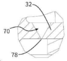
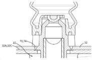
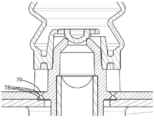
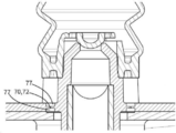
도 2 및 도 2a는 토출 헤드의 단면도로 확대된 제 1 예시적인 실시예를 도시한다.
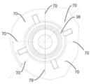
도 3은 액체 저장소로부터 볼 때 토출 헤드의 단부 벽에 환기 구멍의 배열을 도시한다.
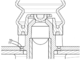
도 4는 분배기의 배향이 거꾸로 된 경우 환기 구멍의 작용을 보여준다.
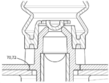
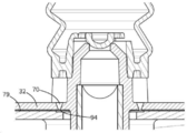
도 5 및 도 5a는 토출 헤드의 단면도로 확대된 제 2 예시적인 실시예를 도시한다.
도 6a 내지 도 6h는 환기 구멍의 형성에 관한 상이한 변형을 도시한다.
도 7은 토출 헤드의 부분 소수성 실시예의 배열 및 효과를 도시한다.
Claims (15)
- 화장품 또는 제약 액체를 분배하기 위한 액체 분배기(100)를 위한 토출 헤드(20)로서,
a. 토출 헤드(20)는 액체 저장소(10)의 출구 커넥터(12)에 고정하기 위한 결합 장치(36)를 가지며,
b. 토출 헤드(20)는 액체 저장소(10)의 방향을 향하는 액체 입구(34)를 갖고 토출 개구(44)를 가지며,
c. 토출 헤드(20)는 액체 입구(34)로부터 토출 개구(44)로 액체를 이송하기 위한 펌프 장치(50)를 가지며,
d. 토출 헤드(20)는 토출 헤드(20)의 외부 주변을 액체 저장소(10)의 내부에 연결하는 환기 채널(60)을 가지는, 상기 토출 헤드에 있어서,
e. 토출 헤드(20)는 토출 헤드(20) 측의 출구 커넥터(12)의 원위 단부에서 결합식 액체 저장소(10)가 실질적으로 폐쇄되고 액체 입구(34)에 의해 연장되는 단부 표면(32)을 가지며,
f. 단부 표면(32) 및 결합 장치(36)는 공통 주 구성 요소(30)의 일부로서 단일 부분 방식으로 형성되고,
g. 단부 표면(32)은 환기 채널(60)의 일부이고 공기가 유입 방향(2)으로 액체 저장소(10) 내로 유동할 수 있는 적어도 하나의 환기 구멍(70)을 가지며,
h. 적어도 하나의 환기 구멍(70)은 최대 3·10-2 ㎟, 바람직하게는 최대 1·10-2 ㎟, 특히 바람직하게는 최대 5·10-3 ㎟의 최소 투명 단면(80)을 갖는 것을 특징으로 하는 토출 헤드. - 제 1 항에 있어서,
a. 환기 구멍(70)은 유입 방향(2)으로 꾸준히 좁아지는 개구로서 형성되는 추가의 특징을 갖는, 토출 헤드. - 제 1 항에 있어서,
a. 환기 구멍(70)은 유입 방향(2)에 반대로 좁아지는 개구로서 형성되는 추가의 특징을 갖는, 토출 헤드. - 제 1 항 내지 제 3 항 중 어느 한 항에 있어서,
a. 환기 구멍(70)은 최소 투명 단면(80)의 위치에서, 그 길이가 적어도 상기 위치에서의 평균 직경에 대응하는 원통형 채널 부분(72)에 의해 형성되는 추가의 특징을 갖는, 토출 헤드. - 제 1 항 내지 제 4 항 중 어느 한 항에 있어서,
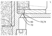
a. 환기 구멍(70)은 절두 원추형 또는 절두 피라미드형 채널 부분(74, 75)을 가지며, 가장 좁은 지점은 환기 구멍의 최소 투명 단면(80)을 형성하는 추가의 특징을 갖고,
특히,
b. 절두 원추형 또는 절두 피라미드형 채널 부분(74)은 공기의 유입 방향으로 좁아지는 추가의 특징, 및/또는
c. 절두 원추형 또는 절두 피라미드형 채널 부분(75)은 공기의 유입 방향에 반대로 좁아지는 추가의 특징, 및/또는
d. 가장 작은 투명 단면(80)은 액체 저장소(10)를 향하는 단부의 단부 표면(32)의 표면(32A)의 평면 또는 액체 저장소(10)의 반대쪽의 단부의 단부 표면(32)의 표면(32B)의 평면에 배열되는 추가의 특징
중 적어도 하나를 갖는, 토출 헤드. - 제 1 항 내지 제 5 항 중 어느 한 항에 있어서,
a. 다수의 환기 구멍(70), 바람직하게는 2, 3, 4, 5, 6 또는 8 개의 환기 구멍이 제공되는 추가의 특징을 갖고,
바람직하게는,
b. 원주 방향으로 서로 가장 많이 이격된 2 개의 환기 구멍(70)은 서로 적어도 60 ° 및/또는 적어도 5mm 이격되어 있는 추가의 특징을 갖는, 토출 헤드. - 제 1 항 내지 제 6 항 중 어느 한 항에 있어서,
a. 주 구성 요소(30)는, 첨가제를 첨가하여, 완전히 친수성 또는 소수성 구성 요소로서 형성되는 플라스틱으로 제조되는 추가의 특징, 및/또는
b. 주 구성 요소(30)는, 단부 표면(32)에, 한쪽 또는 양쪽에 친수성 또는 소수성 코팅이 제공되는 추가의 특징
중 하나를 갖는, 토출 헤드. - 제 1 항 내지 제 7 항 중 어느 한 항에 있어서,
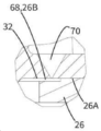
a. 토출 헤드(20)는 액체 저장소(10)의 출구 커넥터(12)에 대하여 토출 헤드(20)를 원주 방향으로 밀봉하기 위한 밀봉 링(26)을 가지는 추가의 특징, 및
b. 밀봉 링(26)은 액체 저장소(10)의 출구 커넥터(12)의 주요 범위 방향(4)에 대해, 상기 밀봉 링이 적어도 하나의 환기 구멍(70)을 커버하도록 면적 범위를 갖는 추가의 특징, 및
c. 밀봉 링(26)은 좁은 슬롯(68)을 형성하도록 환기 구멍(70)의 출구 측으로부터 이격되어, 공기가 밀봉 링(26)을 지나 액체 저장소(10) 내로 통과할 수 있는 추가의 특징
을 갖는, 토출 헤드. - 제 8 항에 있어서,
a. 액체 저장소(10)를 향하는 단부 표면(32)의 해당 측면은 밀봉 링(26)이 지지되는 평면 접합 표면(32C)을 가지는 추가의 특징,
b. 액체 저장소를 향하는 단부 표면(32)의 해당 측면은, 접합 표면(32C)에 대해 오목하고 적어도 하나의 환기 구멍(70)이 개방되는 영역(32D)을 갖는 추가의 특징
을 갖는, 토출 헤드. - 제 8 항 또는 제 9 항에 있어서,
a. 밀봉 링(26)은 단부 표면(32)에 대해 지지되는 평면 접합 표면(26A)을 갖는 추가의 특징, 및
b. 밀봉 링(26)은, 단부 표면(32)을 향하는 밀봉 링(26)의 측면에서, 접합 표면(26A)에 대해 오목하고 바람직하게는 액체 입구(34)를 둘러싸는 함몰부로서 형성되는 영역(26B)을 갖고, 상기 리세스 영역(26B)은 상기 적어도 하나의 환기 구멍(70)이 상기 밀봉 링(26)의 상기 리세스 영역(26B) 내로 개방되도록 배치되는 추가의 특징
을 갖는, 토출 헤드. - 제 1 항 내지 제 10 항 중 어느 한 항에 있어서,
a. 토출 헤드(20)는 주 구성 요소(30)에 슬라이딩 방식으로 장착되는 작동 푸시 버튼(40)을 갖는 추가의 특징, 및/또는
b. 토출 헤드(20)는 주 구성 요소(30)와 함께, 펌프 장치(50)의 펌프 챔버(52)가 배치되는 내부 공간을 한정하는 작동 푸시 버튼(40)을 갖는 추가의 특징
중 적어도 하나를 갖는, 토출 헤드. - 제 1 항 내지 제 11 항 중 어느 한 항에 있어서,
a. 펌프 장치(50)는 입구 측(54A) 및 출구 측(54B)에서 개방형인 탄성 압축성 중공 본체(54)에 의해 형성된 펌프 챔버(52)를 갖는 추가의 특징을 가지며,
바람직하게는,
b. 펌프 챔버(52)는, 입구 측(54A)에, 중공 본체(54)와 일체로 형성된 입구 밸브 부분(56A)에 의해 적어도 부분적으로 형성된 입구 밸브(56)를 갖는 추가의 특징, 및/또는
c. 펌프 챔버(52)는, 출구 측(54B)에, 중공 본체(54)와 일체로 형성된 출구 밸브 부분(58A)에 의해 적어도 부분적으로 형성된 출구 밸브(58)를 갖는 추가의 특징
중 적어도 하나를 갖는, 토출 헤드. - 제 1 항 내지 제 12 항 중 어느 한 항에 있어서,
a. 주 구성 요소(30)는 액체 저장소에 대해 반대쪽 단부 표면(32) 너머로 돌출하고 펌프 챔버(52)를 형성하는 중공 본체(54)의 이격된 부착을 제공하는 펌프 챔버 커넥터(38)를 갖는 특징 - 정지 표면(38A)이 특히 바람직하게는 펌프 챔버 커넥터(38) 상에 제공되며, 상기 정지 표면에 대해 중공 본체(54)의 입구 측(54A)이 지지됨 - , 및/또는
b. 결합 장치(36)는 내부 나사산 방식으로 형성되는 특징, 및/또는
c. 결합 장치는 디텐트 장치로 설계되고, 이 목적을 위해, 주 구성 요소 상에, 액체 저장소의 커넥터 상의 디텐트 결합을 위한 적어도 하나의 탄성 편향 가능한 디텐트 에지가 제공되는 특징, 및/또는
d. 환기 구멍(70)을 둘러싸는 벽은, 환기 구멍 중에, 벽의 일부가 적어도 135 °의 각도로 서로 수렴하고 0.1mm 미만의 곡률 반경을 갖는 예리한 형태인 적어도 하나의 표면 형성 에지(78)를 갖는 특징, 및/또는
e. 적어도 하나의 환기 구멍(70)의 중심 축은 액체 저장소(10)의 출구 커넥터(12)의 주 범위 방향(4)에 평행하게 연장되는 특징
중 적어도 하나를 갖는, 토출 헤드. - 화장품 분배용 액체 분배기(100)로서,
a. 액체 분배기(100)는 출구 커넥터(12)를 갖는 액체 저장소(10)를 갖는 특징, 및
b. 액체 분배기(100)는 결합 장치(36)에 의해 출구 커넥터(12)에 고정되는 토출 헤드(20)를 갖는 특징을 가지며,
c. 토출 헤드(20)는 전술한 청구항 중 어느 한 항에 청구된 바와 같이 설계되는 추가의 특징을 특징으로 하는 액체 분배기. - 제 14 항에 있어서,
a. 액체 저장소(10)는 화장품 액체로 채워지는 추가의 특징, 및
b. 적어도 하나의 환기 구멍(70)의 가장 작은 투명 직경은 액체 저장소(10) 내의 액체에 의해 최대로 발생되는 정수압이 액체의 표면 장력으로 인해 환기 구멍(70)을 통과할 수 없도록 구성되는 추가의 특징
을 갖는, 액체 분배기.
Applications Claiming Priority (3)
| Application Number | Priority Date | Filing Date | Title |
|---|---|---|---|
| EP17181284.5 | 2017-07-13 | ||
| EP17181284.5A EP3427839B1 (de) | 2017-07-13 | 2017-07-13 | Flüssigkeitsspender mit belüfteter flasche und austragkopf hierfür |
| PCT/EP2018/066685 WO2019011621A1 (de) | 2017-07-13 | 2018-06-21 | Flüssigkeitsspender mit belüfteter flasche und austragkopf hierfür |
Publications (1)
| Publication Number | Publication Date |
|---|---|
| KR20200029537A true KR20200029537A (ko) | 2020-03-18 |
Family
ID=59337583
Family Applications (1)
| Application Number | Title | Priority Date | Filing Date |
|---|---|---|---|
| KR1020207004176A Ceased KR20200029537A (ko) | 2017-07-13 | 2018-06-21 | 환기식 병 및 이를 위한 토출 헤드를 갖는 액체 분배기 |
Country Status (5)
| Country | Link |
|---|---|
| US (1) | US11213843B2 (ko) |
| EP (1) | EP3427839B1 (ko) |
| KR (1) | KR20200029537A (ko) |
| CN (1) | CN110831703B (ko) |
| WO (1) | WO2019011621A1 (ko) |
Families Citing this family (10)
| Publication number | Priority date | Publication date | Assignee | Title |
|---|---|---|---|---|
| US11236794B2 (en) * | 2018-01-03 | 2022-02-01 | Silgan Dispensing Systems Corporation | Dispensing pump with polymer spring, base venting and flow baffle |
| FR3090415B1 (fr) * | 2018-12-24 | 2024-07-12 | Albea Services | Pompe pour flacon de produit cosmétique, étanche en conditions de basse pression |
| FR3090416B1 (fr) * | 2018-12-24 | 2024-07-12 | Albea Services | Pompe pour flacon de produit cosmétique dotée de moyens de purge d’air |
| EP3736049B1 (de) | 2019-05-06 | 2022-11-09 | Aptar Radolfzell GmbH | Austragkopf und flüssigkeitsspender mit einem austragkopf |
| EP3821987B1 (de) * | 2019-11-15 | 2022-09-28 | Aptar Radolfzell GmbH | Flüssigkeitsspender mit flaschenbelüftung |
| US12403492B2 (en) * | 2020-04-07 | 2025-09-02 | Samhwa Co., Ltd | Pump cap |
| US12173768B2 (en) * | 2020-04-29 | 2024-12-24 | Yonwoo Co., Ltd. | Elastic member and pump assembly including the same |
| EP3978389B1 (de) * | 2020-10-02 | 2023-03-01 | Aptar Radolfzell GmbH | Flüssigkeitsspender, insbesondere tropfenspender |
| WO2023049693A2 (en) | 2021-09-24 | 2023-03-30 | Johnson & Johnson Consumer Inc. | Dosage forms for the delivery of a probiotic |
| KR102572953B1 (ko) * | 2021-12-31 | 2023-08-31 | (주)성진코스메틱스 | 화장품 용기 및 화장품 용기용 펌핑부재 |
Family Cites Families (19)
| Publication number | Priority date | Publication date | Assignee | Title |
|---|---|---|---|---|
| US4235344A (en) | 1979-01-29 | 1980-11-25 | Baxter Travenol Laboratories, Inc. | Irrigation cap |
| DE3620897A1 (de) | 1986-06-21 | 1987-12-23 | Mega Prod Verpack Marketing | Spender |
| US5310094A (en) * | 1991-11-15 | 1994-05-10 | Jsp Partners, L.P. | Preservative free sterile fluid dispensing system |
| US5664703A (en) * | 1994-02-28 | 1997-09-09 | The Procter & Gamble Company | Pump device with collapsible pump chamber having supply container venting system and integral shipping seal |
| DE19605153A1 (de) * | 1996-02-13 | 1997-08-14 | Pfeiffer Erich Gmbh & Co Kg | Austragvorrichtung für Medien und Verfahren zur Herstellung einer Austragvorrichtung o. dgl. |
| US5605257A (en) * | 1996-03-04 | 1997-02-25 | Beard; Walter C. | Sterile liquid squeeze-bottle-type dispenser |
| DE19851404A1 (de) | 1998-11-07 | 2000-05-11 | Boehringer Ingelheim Int | Druckausgleichsvorrichtung für einen Doppelbehälter |
| US20050127107A1 (en) * | 2001-09-21 | 2005-06-16 | Pierre Mbonyumuhire | Dosing device with a medium reservoir and a pump device |
| ES2317962T3 (es) | 2001-09-21 | 2009-05-01 | Ing. Erich Pfeiffer Gmbh | Dispositivo de dosificacion con un contenedor de medios asi como un dispositivo de bombeo. |
| JP4021268B2 (ja) * | 2002-07-24 | 2007-12-12 | 勝利 増田 | 流体吐出ポンプ |
| US20050127105A1 (en) | 2003-12-10 | 2005-06-16 | Kay George W. | Method and apparatus to supply a viscous liquid |
| DE102004044344A1 (de) * | 2004-09-09 | 2006-03-30 | Ing. Erich Pfeiffer Gmbh | Dosiervorrichtung |
| ATE383205T1 (de) * | 2005-02-22 | 2008-01-15 | Pfeiffer Erich Gmbh & Co Kg | Spender für medien sowie montageverfahren hierfür |
| FR2915467B1 (fr) * | 2007-04-24 | 2009-06-05 | Plastohm Division Emballages S | Dispositif et distribution d'un produit liquide a pateux par pompe de dosage. |
| EP2442913B1 (en) | 2009-06-17 | 2019-03-06 | S.C. Johnson & Son, Inc. | Handheld device for dispensing fluids |
| GB2474520B (en) * | 2009-10-19 | 2015-08-26 | London & General Packaging Ltd | Spray dispenser |
| DE102009051570B3 (de) | 2009-10-23 | 2011-06-22 | Ing. Erich Pfeiffer GmbH, 78315 | Austragvorrichtung |
| DE102013211423A1 (de) * | 2013-06-18 | 2014-12-31 | Aptar Radolfzell Gmbh | Mehrschichtiger Behälter |
| US10478022B2 (en) * | 2017-05-24 | 2019-11-19 | The Clorox Company | On demand wet wipe dispensing device |
-
2017
- 2017-07-13 EP EP17181284.5A patent/EP3427839B1/de active Active
-
2018
- 2018-06-21 KR KR1020207004176A patent/KR20200029537A/ko not_active Ceased
- 2018-06-21 US US16/629,135 patent/US11213843B2/en active Active
- 2018-06-21 WO PCT/EP2018/066685 patent/WO2019011621A1/de not_active Ceased
- 2018-06-21 CN CN201880046760.2A patent/CN110831703B/zh active Active
Also Published As
| Publication number | Publication date |
|---|---|
| CN110831703B (zh) | 2021-12-07 |
| EP3427839B1 (de) | 2020-12-02 |
| US11213843B2 (en) | 2022-01-04 |
| US20200130002A1 (en) | 2020-04-30 |
| WO2019011621A1 (de) | 2019-01-17 |
| CN110831703A (zh) | 2020-02-21 |
| EP3427839A1 (de) | 2019-01-16 |
Similar Documents
| Publication | Publication Date | Title |
|---|---|---|
| KR20200029537A (ko) | 환기식 병 및 이를 위한 토출 헤드를 갖는 액체 분배기 | |
| EP2700588B1 (en) | Dispensing closure having a vent valve | |
| US6206058B1 (en) | Integrated vent and fluid transfer fitment | |
| CN102725073B (zh) | 液体分配装置 | |
| CN101952177B (zh) | 具有防止狭缝未对准的特征的阀安装组件 | |
| EP3218281B1 (en) | Spout for a refill container | |
| JP2008526636A (ja) | 流れ制御要素、およびそれを組み込んだ分配構造体 | |
| CN1617822A (zh) | 喷雾阀装置 | |
| ES2912470T3 (es) | Tapa de pulverización para contenedor de pulverización | |
| KR20070121587A (ko) | 유체 디스펜서 노즐 및 그러한 노즐을 포함하는 유체디스펜서 장치 | |
| WO2015182041A1 (ja) | トリガー式液体噴出器 | |
| KR20190083646A (ko) | 배출 헤드 및 이러한 배출 헤드를 포함하는 액체 디스펜서 | |
| JP2019043644A (ja) | キャップ | |
| JP3822352B2 (ja) | 正倒立両用の液体噴出器 | |
| US20160138953A1 (en) | Liquid dispenser and discharge head for same | |
| KR20220003103A (ko) | 배출 헤드 및 배출 헤드를 포함하는 액체 분배기 | |
| KR100858320B1 (ko) | 유체용기 | |
| JP6475960B2 (ja) | エアーバックレスキャップ、およびこのキャップを備えた容器 | |
| KR101618122B1 (ko) | 공기 유입 차단이 가능한 튜브용기 | |
| JP5116521B2 (ja) | 液体用容器 | |
| JP6643855B2 (ja) | キャップ | |
| KR200467361Y1 (ko) | 자동 개폐 플러그를 갖는 튜브형 용기 | |
| JP7074522B2 (ja) | 吐出キャップ | |
| KR102643135B1 (ko) | 액체 분사를 위한 용기 | |
| JP7254341B2 (ja) | キャップ及び容器 |
Legal Events
| Date | Code | Title | Description |
|---|---|---|---|
| PA0105 | International application |
Patent event date: 20200212 Patent event code: PA01051R01D Comment text: International Patent Application |
|
| PG1501 | Laying open of application | ||
| PA0201 | Request for examination |
Patent event code: PA02012R01D Patent event date: 20210305 Comment text: Request for Examination of Application |
|
| E902 | Notification of reason for refusal | ||
| PE0902 | Notice of grounds for rejection |
Comment text: Notification of reason for refusal Patent event date: 20220705 Patent event code: PE09021S01D |
|
| E601 | Decision to refuse application | ||
| PE0601 | Decision on rejection of patent |
Patent event date: 20230118 Comment text: Decision to Refuse Application Patent event code: PE06012S01D Patent event date: 20220705 Comment text: Notification of reason for refusal Patent event code: PE06011S01I |