KR20200034978A - 배터리 시스템 과전압 방지 장치 - Google Patents
배터리 시스템 과전압 방지 장치 Download PDFInfo
- Publication number
- KR20200034978A KR20200034978A KR1020200035457A KR20200035457A KR20200034978A KR 20200034978 A KR20200034978 A KR 20200034978A KR 1020200035457 A KR1020200035457 A KR 1020200035457A KR 20200035457 A KR20200035457 A KR 20200035457A KR 20200034978 A KR20200034978 A KR 20200034978A
- Authority
- KR
- South Korea
- Prior art keywords
- battery
- voltage
- unit
- power
- overvoltage protection
- Prior art date
- Legal status (The legal status is an assumption and is not a legal conclusion. Google has not performed a legal analysis and makes no representation as to the accuracy of the status listed.)
- Granted
Links
Images


Classifications
-
- H—ELECTRICITY
- H02—GENERATION; CONVERSION OR DISTRIBUTION OF ELECTRIC POWER
- H02J—ELECTRIC POWER NETWORKS; CIRCUIT ARRANGEMENTS OR SYSTEMS FOR SUPPLYING OR DISTRIBUTING ELECTRIC POWER; SYSTEMS FOR STORING ELECTRIC ENERGY
- H02J7/00—Circuit arrangements for charging or discharging batteries or for supplying loads from batteries
- H02J7/60—Circuit arrangements for charging or discharging batteries or for supplying loads from batteries including safety or protection arrangements
- H02J7/663—Circuit arrangements for charging or discharging batteries or for supplying loads from batteries including safety or protection arrangements using battery or load disconnect circuits
-
- H—ELECTRICITY
- H02—GENERATION; CONVERSION OR DISTRIBUTION OF ELECTRIC POWER
- H02J—ELECTRIC POWER NETWORKS; CIRCUIT ARRANGEMENTS OR SYSTEMS FOR SUPPLYING OR DISTRIBUTING ELECTRIC POWER; SYSTEMS FOR STORING ELECTRIC ENERGY
- H02J7/00—Circuit arrangements for charging or discharging batteries or for supplying loads from batteries
- H02J7/60—Circuit arrangements for charging or discharging batteries or for supplying loads from batteries including safety or protection arrangements
- H02J7/65—Circuit arrangements for charging or discharging batteries or for supplying loads from batteries including safety or protection arrangements against overtemperature
-
- H—ELECTRICITY
- H02—GENERATION; CONVERSION OR DISTRIBUTION OF ELECTRIC POWER
- H02H—EMERGENCY PROTECTIVE CIRCUIT ARRANGEMENTS
- H02H7/00—Emergency protective circuit arrangements specially adapted for specific types of electric machines or apparatus or for sectionalised protection of cable or line systems, and effecting automatic switching in the event of an undesired change from normal working conditions
- H02H7/18—Emergency protective circuit arrangements specially adapted for specific types of electric machines or apparatus or for sectionalised protection of cable or line systems, and effecting automatic switching in the event of an undesired change from normal working conditions for batteries; for accumulators
-
- G—PHYSICS
- G01—MEASURING; TESTING
- G01R—MEASURING ELECTRIC VARIABLES; MEASURING MAGNETIC VARIABLES
- G01R15/00—Details of measuring arrangements of the types provided for in groups G01R17/00 - G01R29/00, G01R33/00 - G01R33/26 or G01R35/00
- G01R15/04—Voltage dividers
-
- G—PHYSICS
- G01—MEASURING; TESTING
- G01R—MEASURING ELECTRIC VARIABLES; MEASURING MAGNETIC VARIABLES
- G01R19/00—Arrangements for measuring currents or voltages or for indicating presence or sign thereof
- G01R19/165—Indicating that current or voltage is either above or below a predetermined value or within or outside a predetermined range of values
- G01R19/16533—Indicating that current or voltage is either above or below a predetermined value or within or outside a predetermined range of values characterised by the application
- G01R19/16538—Indicating that current or voltage is either above or below a predetermined value or within or outside a predetermined range of values characterised by the application in AC or DC supplies
- G01R19/16542—Indicating that current or voltage is either above or below a predetermined value or within or outside a predetermined range of values characterised by the application in AC or DC supplies for batteries
-
- H01M2/10—
-
- H02J7/00302—
-
- H02J7/0031—
-
- H—ELECTRICITY
- H02—GENERATION; CONVERSION OR DISTRIBUTION OF ELECTRIC POWER
- H02J—ELECTRIC POWER NETWORKS; CIRCUIT ARRANGEMENTS OR SYSTEMS FOR SUPPLYING OR DISTRIBUTING ELECTRIC POWER; SYSTEMS FOR STORING ELECTRIC ENERGY
- H02J7/00—Circuit arrangements for charging or discharging batteries or for supplying loads from batteries
- H02J7/60—Circuit arrangements for charging or discharging batteries or for supplying loads from batteries including safety or protection arrangements
- H02J7/63—Circuit arrangements for charging or discharging batteries or for supplying loads from batteries including safety or protection arrangements against overdischarge
-
- Y—GENERAL TAGGING OF NEW TECHNOLOGICAL DEVELOPMENTS; GENERAL TAGGING OF CROSS-SECTIONAL TECHNOLOGIES SPANNING OVER SEVERAL SECTIONS OF THE IPC; TECHNICAL SUBJECTS COVERED BY FORMER USPC CROSS-REFERENCE ART COLLECTIONS [XRACs] AND DIGESTS
- Y02—TECHNOLOGIES OR APPLICATIONS FOR MITIGATION OR ADAPTATION AGAINST CLIMATE CHANGE
- Y02E—REDUCTION OF GREENHOUSE GAS [GHG] EMISSIONS, RELATED TO ENERGY GENERATION, TRANSMISSION OR DISTRIBUTION
- Y02E60/00—Enabling technologies; Technologies with a potential or indirect contribution to GHG emissions mitigation
- Y02E60/10—Energy storage using batteries
Landscapes
- Engineering & Computer Science (AREA)
- Power Engineering (AREA)
- Physics & Mathematics (AREA)
- General Physics & Mathematics (AREA)
- Charge And Discharge Circuits For Batteries Or The Like (AREA)
- Chemical & Material Sciences (AREA)
- Chemical Kinetics & Catalysis (AREA)
- Electrochemistry (AREA)
- General Chemical & Material Sciences (AREA)
- Secondary Cells (AREA)
Abstract
Description
도 2는 본 발명의 일 실시예에 따른 배터리 시스템 과전압 방지 장치의 전원 차단부의 연결을 보여주는 예시도.
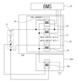
도 3은 본 발명의 일 실시예에 따른 배터리 시스템 과전압 방지 장치의 회로도.
도 4는 본 발명의 일 실시예에 따른 배터리 시스템 과전압 방지 장치에 있어서, 과충전 상태가 아닌 경우를 보여주는 회로도.
도 5는 본 발명의 일 실시예에 따른 배터리 시스템 과전압 방지 장치에 있어서, 과충전 상태를 보여주는 회로도.
도 6은 본 발명의 일 실시예에 따른 안전부를 포함한 배터리 시스템 과전압 방지 장치를 보여주는 회로도.
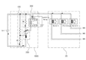
도 7은 본 발명의 일 실시예에 따른 배터리 시스템 과전압 방지 장치를 구현한 예를 보여주는 회로도.
도 8은 본 발명의 일 실시예에 따른 안전부를 포함한 배터리 시스템 과전압 방지 장치를 구현한 예를 보여주는 회로도.
20: 파워 릴레이 어셈블리
21: 제1 메인 릴레이
22: 제2 메인 릴레이
23: 프리차지 릴레이
24: 프리차지 저항
30: 배터리 관리 장치
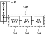
100: 입력전압 분배부
200: 전압 감지부
300: 전원 차단부
Claims (14)
- 복수 개의 배터리 셀들을 포함한 배터리 팩에서,
배터리 관리 장치와 별도로 적어도 하나의 배터리 셀의 전압을 감지하여, 일정전압 이상 감지되면 동작하는 전압 감지부; 및
배터리 관리 장치와 별도로 상기 전압 감지부의 동작에 의해 내부 스위치를 온 또는 오프 시켜, 상기 배터리 팩과 외부 시스템을 연결해주는 메인 릴레이를 직접 차단시키는 전원 차단부;
를 포함하는 배터리 시스템 과전압 방지 장치.
- 제 1항에 있어서,
상기 전압 감지부는,
아날로그 회로로만 구성되고;
배터리 셀의 전압이 일정 전압 이상이면, 상기 배터리 관리 장치의 정상동작 또는 오동작 여부와 관계없이 독립적으로 상기 메인 릴레이가 차단되도록, 상기 전원 차단부의 내부 스위치를 온 또는 오프 제어하는 배터리 시스템 과전압 방지 장치.
- 제 1항에 있어서,
상기 배터리 시스템 과전압 방지 장치는
적어도 하나의 배터리 셀의 양단에 연결되며, 상기 적어도 하나의 배터리 셀의 전압을 분배하는 입력전압 분배부;를 더 포함하며,
상기 전압 감지부는 상기 입력전압 분배부와 연결되며, 상기 입력전압 분배부를 통해 입력된 전압이 일정전압 이상 감지되면 상기 배터리 팩의 과전압으로 판단하여 상기 메인 릴레이가 차단되도록 동작하는 배터리 시스템 과전압 방지 장치.
- 제 3항에 있어서,
상기 전압 감지부는
상기 배터리 관리 장치와 독립적으로 적어도 하나의 배터리 셀의 전압을 감지하여 일정전압 이상 감지되면 동작할 수 있도록 아날로그 회로로 구성되는 배터리 시스템 과전압 방지 장치. - 제 4항에 있어서,
상기 입력전압 분배부는 직렬로 연결되는 복수 개의 저항을 포함하는 배터리 시스템 과전압 방지 장치.
- 제 5항에 있어서,
상기 전압 감지부는
션트 레귤레이터로 구성되며, 상기 션트 레귤레이터의 레퍼런스는 상기 입력전압 분배부의 저항과 저항 사이에 연결되고, 상기 션트 레귤레이터의 캐소드는 상기 전원 차단부의 일측과 연결되며, 상기 션트 레귤레이터의 애노드는 상기 입력전압 분배부와 연결된 상기 배터리 셀의 음극과 연결되고,
상기 입력전압 분배부를 이용하여 분배된 입력전압이 일정전압 이상으로 입력되면 상기 션트 레귤레이터의 캐소드와 애노드가 통전되는 배터리 시스템 과전압 방지 장치.
- 제 6항에 있어서,
상기 전원 차단부는
코일부와 스위치부를 포함하는 내부 스위치를 포함하며,
상기 코일부의 일측은 상기 배터리 셀의 양극과 연결되고 상기 코일부의 타측은 상기 션트 레귤레이터의 캐소드와 연결되며,
상기 스위치부의 일측은 상기 메인 릴레이의 코일측 선로와 연결되고 상기 스위치부의 타측은 그라운드 공통선과 연결되는 배터리 시스템 과전압 방지 장치.
- 제 7항에 있어서,
상기 전원 차단부는
상기 전압 감지부의 동작에 의해 상기 코일부에 전원이 인가되면 상기 스위치부가 동작되며, 별도의 제어가 있기 전까지 동작 상태를 그대로 유지시키는 비복귀 회로로 구성되는 배터리 시스템 과전압 방지 장치.
- 제 7항에 있어서,
상기 전원 차단부의 내부 스위치는 래칭 릴레이로 구성되는 배터리 시스템 과전압 방지 장치.
- 제 7항에 있어서,
상기 전원 차단부는
상기 전원 차단부의 코일부 사이에 병렬로 연결된 저항을 포함하는 배터리 시스템 과전압 방지 장치.
- 제 7항에 있어서,
상기 적어도 하나의 배터리 셀의 양단 또는 상기 션트 레귤레이터의 애노드와 상기 션트 레귤레이터의 레퍼런스에 연결되는 안전부;
를 더 포함하는 배터리 시스템 과전압 방지 장치.
- 제 11항에 있어서,
상기 안전부는
커패시터, TVS 다이오드 중 선택되는 적어도 어느 하나인 배터리 시스템 과전압 방지 장치.
- 제 1항에 있어서,
상기 배터리 셀과 연결되는 파워 릴레이 어셈블리에 포함되는 상기 메인 릴레이의 코일은 상기 배터리 관리 장치와 일단이 직렬 연결되고, 상기 전원 차단부와 타단이 직렬 연결되는 배터리 시스템 과전압 방지 장치.
- 제 1항에 있어서,
상기 메인 릴레이를 구성하는 코일의 상기 배터리 셀과 연결되는 파워 릴레이 어셈블리에 포함되는 프리차지 릴레이의 코일은 상기 배터리 관리 장치와 일단이 직렬 연결되고, 상기 전원 차단부와 타단이 직렬 연결되는 배터리 시스템 과전압 방지 장치.
Priority Applications (1)
| Application Number | Priority Date | Filing Date | Title |
|---|---|---|---|
| KR1020200035457A KR102258736B1 (ko) | 2017-06-02 | 2020-03-24 | 배터리 시스템 과전압 방지 장치 |
Applications Claiming Priority (2)
| Application Number | Priority Date | Filing Date | Title |
|---|---|---|---|
| KR1020170068902A KR102218431B1 (ko) | 2017-06-02 | 2017-06-02 | 배터리 시스템 과전압 방지 장치 |
| KR1020200035457A KR102258736B1 (ko) | 2017-06-02 | 2020-03-24 | 배터리 시스템 과전압 방지 장치 |
Related Parent Applications (1)
| Application Number | Title | Priority Date | Filing Date |
|---|---|---|---|
| KR1020170068902A Division KR102218431B1 (ko) | 2017-06-02 | 2017-06-02 | 배터리 시스템 과전압 방지 장치 |
Publications (2)
| Publication Number | Publication Date |
|---|---|
| KR20200034978A true KR20200034978A (ko) | 2020-04-01 |
| KR102258736B1 KR102258736B1 (ko) | 2021-05-31 |
Family
ID=70276338
Family Applications (1)
| Application Number | Title | Priority Date | Filing Date |
|---|---|---|---|
| KR1020200035457A Active KR102258736B1 (ko) | 2017-06-02 | 2020-03-24 | 배터리 시스템 과전압 방지 장치 |
Country Status (1)
| Country | Link |
|---|---|
| KR (1) | KR102258736B1 (ko) |
Cited By (1)
| Publication number | Priority date | Publication date | Assignee | Title |
|---|---|---|---|---|
| US12556018B2 (en) | 2020-10-26 | 2026-02-17 | Lg Energy Solution, Ltd. | Charging management apparatus, charging management method, and electric vehicle |
Families Citing this family (1)
| Publication number | Priority date | Publication date | Assignee | Title |
|---|---|---|---|---|
| KR102941751B1 (ko) * | 2024-10-31 | 2026-03-19 | (주) 케이티클라우드 | 데이터 센터의 냉방 제어를 위한 제어 시스템 |
Citations (5)
| Publication number | Priority date | Publication date | Assignee | Title |
|---|---|---|---|---|
| JPH04244778A (ja) * | 1991-01-31 | 1992-09-01 | Nippon Electric Ind Co Ltd | 過電流検出回路 |
| JPH05268732A (ja) * | 1992-03-17 | 1993-10-15 | Sanyo Electric Co Ltd | 電池の充電装置 |
| JP2000014020A (ja) * | 1998-06-18 | 2000-01-14 | Matsushita Electric Ind Co Ltd | 安全装置、電池パック及び電子機器 |
| JP2006101657A (ja) * | 2004-09-30 | 2006-04-13 | Matsushita Electric Works Ltd | 充電装置 |
| US20110298463A1 (en) | 2010-06-04 | 2011-12-08 | Hiroshi Saito | Battery state monitoring circuit and battery device |
-
2020
- 2020-03-24 KR KR1020200035457A patent/KR102258736B1/ko active Active
Patent Citations (5)
| Publication number | Priority date | Publication date | Assignee | Title |
|---|---|---|---|---|
| JPH04244778A (ja) * | 1991-01-31 | 1992-09-01 | Nippon Electric Ind Co Ltd | 過電流検出回路 |
| JPH05268732A (ja) * | 1992-03-17 | 1993-10-15 | Sanyo Electric Co Ltd | 電池の充電装置 |
| JP2000014020A (ja) * | 1998-06-18 | 2000-01-14 | Matsushita Electric Ind Co Ltd | 安全装置、電池パック及び電子機器 |
| JP2006101657A (ja) * | 2004-09-30 | 2006-04-13 | Matsushita Electric Works Ltd | 充電装置 |
| US20110298463A1 (en) | 2010-06-04 | 2011-12-08 | Hiroshi Saito | Battery state monitoring circuit and battery device |
Cited By (1)
| Publication number | Priority date | Publication date | Assignee | Title |
|---|---|---|---|---|
| US12556018B2 (en) | 2020-10-26 | 2026-02-17 | Lg Energy Solution, Ltd. | Charging management apparatus, charging management method, and electric vehicle |
Also Published As
| Publication number | Publication date |
|---|---|
| KR102258736B1 (ko) | 2021-05-31 |
Similar Documents
| Publication | Publication Date | Title |
|---|---|---|
| KR20150012425A (ko) | 배터리 과충전 방지 장치 | |
| EP2171824B1 (en) | Method of deactivating faulty battery cells | |
| KR101891687B1 (ko) | 배터리 모듈 분리 장치 | |
| EP2894759B1 (en) | Secondary Battery Protection With Permanent Disable | |
| US9941712B2 (en) | Electrical storage system | |
| JP2013519357A (ja) | 高出力バッテリシステムおよび高出力バッテリシステムを制御するための方法 | |
| US10759297B2 (en) | Charging station having differential current monitoring for charging an electric energy storage means of an electric vehicle | |
| KR101882835B1 (ko) | 배터리 과충전 감지 장치 | |
| US20130249278A1 (en) | Battery system and method of operating the battery system | |
| KR20190005954A (ko) | 불꽃 회로 보호 시스템, 모듈 및 방법 | |
| US9472941B2 (en) | Battery module | |
| CN110832732A (zh) | 电池的保护电路和具备该保护电路的电源装置 | |
| EP3975380B1 (en) | Battery control device and short circuit detection method thereof | |
| KR102218431B1 (ko) | 배터리 시스템 과전압 방지 장치 | |
| KR102258736B1 (ko) | 배터리 시스템 과전압 방지 장치 | |
| US10686312B2 (en) | Monitoring unit for monitoring a circuit breaker comprising an electrical power supply management system and circuit breaker comprising such a unit | |
| AU2008201759A1 (en) | Fail safe battery management system | |
| JP7836582B2 (ja) | 直列接続されたセル及び内部リレーを備えた高電圧バッテリモジュール | |
| CN111095719B (zh) | 蓄电池装置 | |
| EP3534485B1 (en) | Battery pack, battery management system, and method therefor | |
| WO2015037210A1 (ja) | 切替回路 | |
| JP3331200B2 (ja) | モジュール電池の保護装置及び蓄電装置 | |
| KR20150026370A (ko) | 배터리 과충전 방지 장치 | |
| KR102363568B1 (ko) | 배터리 모듈 과충전 방지 장치 | |
| CN118661105A (zh) | 用于半导体开关的功能检查的方法和布置系统 |
Legal Events
| Date | Code | Title | Description |
|---|---|---|---|
| A107 | Divisional application of patent | ||
| PA0107 | Divisional application |
St.27 status event code: A-0-1-A10-A18-div-PA0107 St.27 status event code: A-0-1-A10-A16-div-PA0107 |
|
| PG1501 | Laying open of application |
St.27 status event code: A-1-1-Q10-Q12-nap-PG1501 |
|
| A201 | Request for examination | ||
| PA0201 | Request for examination |
St.27 status event code: A-1-2-D10-D11-exm-PA0201 |
|
| D12-X000 | Request for substantive examination rejected |
St.27 status event code: A-1-2-D10-D12-exm-X000 |
|
| E902 | Notification of reason for refusal | ||
| PE0902 | Notice of grounds for rejection |
St.27 status event code: A-1-2-D10-D21-exm-PE0902 |
|
| T11-X000 | Administrative time limit extension requested |
St.27 status event code: U-3-3-T10-T11-oth-X000 |
|
| T11-X000 | Administrative time limit extension requested |
St.27 status event code: U-3-3-T10-T11-oth-X000 |
|
| E13-X000 | Pre-grant limitation requested |
St.27 status event code: A-2-3-E10-E13-lim-X000 |
|
| P11-X000 | Amendment of application requested |
St.27 status event code: A-2-2-P10-P11-nap-X000 |
|
| P13-X000 | Application amended |
St.27 status event code: A-2-2-P10-P13-nap-X000 |
|
| P22-X000 | Classification modified |
St.27 status event code: A-2-2-P10-P22-nap-X000 |
|
| P22-X000 | Classification modified |
St.27 status event code: A-2-2-P10-P22-nap-X000 |
|
| E701 | Decision to grant or registration of patent right | ||
| PE0701 | Decision of registration |
St.27 status event code: A-1-2-D10-D22-exm-PE0701 |
|
| GRNT | Written decision to grant | ||
| PR0701 | Registration of establishment |
St.27 status event code: A-2-4-F10-F11-exm-PR0701 |
|
| PR1002 | Payment of registration fee |
St.27 status event code: A-2-2-U10-U11-oth-PR1002 Fee payment year number: 1 |
|
| PG1601 | Publication of registration |
St.27 status event code: A-4-4-Q10-Q13-nap-PG1601 |
|
| PN2301 | Change of applicant |
St.27 status event code: A-5-5-R10-R11-asn-PN2301 |
|
| PN2301 | Change of applicant |
St.27 status event code: A-5-5-R10-R14-asn-PN2301 |
|
| R18-X000 | Changes to party contact information recorded |
St.27 status event code: A-5-5-R10-R18-oth-X000 |
|
| P22-X000 | Classification modified |
St.27 status event code: A-4-4-P10-P22-nap-X000 |
|
| PR1001 | Payment of annual fee |
St.27 status event code: A-4-4-U10-U11-oth-PR1001 Fee payment year number: 4 |
|
| PR1001 | Payment of annual fee |
St.27 status event code: A-4-4-U10-U11-oth-PR1001 Fee payment year number: 5 |
|
| P22-X000 | Classification modified |
St.27 status event code: A-4-4-P10-P22-nap-X000 |