KR20200036009A - Thermally changeable color writing tool - Google Patents
Thermally changeable color writing tool Download PDFInfo
- Publication number
- KR20200036009A KR20200036009A KR1020207006126A KR20207006126A KR20200036009A KR 20200036009 A KR20200036009 A KR 20200036009A KR 1020207006126 A KR1020207006126 A KR 1020207006126A KR 20207006126 A KR20207006126 A KR 20207006126A KR 20200036009 A KR20200036009 A KR 20200036009A
- Authority
- KR
- South Korea
- Prior art keywords
- nib
- shaft cylinder
- thermochromic
- friction
- writing tool
- Prior art date
- Legal status (The legal status is an assumption and is not a legal conclusion. Google has not performed a legal analysis and makes no representation as to the accuracy of the status listed.)
- Granted
Links
Images


Classifications
-
- B—PERFORMING OPERATIONS; TRANSPORTING
- B43—WRITING OR DRAWING IMPLEMENTS; BUREAU ACCESSORIES
- B43K—IMPLEMENTS FOR WRITING OR DRAWING
- B43K5/00—Pens with ink reservoirs in holders, e.g. fountain-pens
- B43K5/16—Pens with ink reservoirs in holders, e.g. fountain-pens with retractable nibs
-
- B—PERFORMING OPERATIONS; TRANSPORTING
- B43—WRITING OR DRAWING IMPLEMENTS; BUREAU ACCESSORIES
- B43K—IMPLEMENTS FOR WRITING OR DRAWING
- B43K1/00—Nibs; Writing-points
- B43K1/08—Nibs; Writing-points with ball points; Balls or ball beds
- B43K1/086—Nibs; Writing-points with ball points; Balls or ball beds with resilient supporting means for the ball, e.g. springs
-
- B—PERFORMING OPERATIONS; TRANSPORTING
- B43—WRITING OR DRAWING IMPLEMENTS; BUREAU ACCESSORIES
- B43K—IMPLEMENTS FOR WRITING OR DRAWING
- B43K23/00—Holders or connectors for writing implements; Means for protecting the writing-points
- B43K23/08—Protecting means, e.g. caps
- B43K23/12—Protecting means, e.g. caps for pens
-
- B—PERFORMING OPERATIONS; TRANSPORTING
- B43—WRITING OR DRAWING IMPLEMENTS; BUREAU ACCESSORIES
- B43K—IMPLEMENTS FOR WRITING OR DRAWING
- B43K24/00—Mechanisms for selecting, projecting, retracting or locking writing units
- B43K24/02—Mechanisms for selecting, projecting, retracting or locking writing units for locking a single writing unit in only fully projected or retracted positions
- B43K24/06—Mechanisms for selecting, projecting, retracting or locking writing units for locking a single writing unit in only fully projected or retracted positions operated by turning means
-
- B—PERFORMING OPERATIONS; TRANSPORTING
- B43—WRITING OR DRAWING IMPLEMENTS; BUREAU ACCESSORIES
- B43K—IMPLEMENTS FOR WRITING OR DRAWING
- B43K24/00—Mechanisms for selecting, projecting, retracting or locking writing units
- B43K24/02—Mechanisms for selecting, projecting, retracting or locking writing units for locking a single writing unit in only fully projected or retracted positions
- B43K24/08—Mechanisms for selecting, projecting, retracting or locking writing units for locking a single writing unit in only fully projected or retracted positions operated by push-buttons
- B43K24/082—Mechanisms for selecting, projecting, retracting or locking writing units for locking a single writing unit in only fully projected or retracted positions operated by push-buttons placed on the side
-
- B—PERFORMING OPERATIONS; TRANSPORTING
- B43—WRITING OR DRAWING IMPLEMENTS; BUREAU ACCESSORIES
- B43K—IMPLEMENTS FOR WRITING OR DRAWING
- B43K24/00—Mechanisms for selecting, projecting, retracting or locking writing units
- B43K24/10—Mechanisms for selecting, projecting, retracting or locking writing units for selecting, projecting and locking several writing units
- B43K24/12—Mechanisms for selecting, projecting, retracting or locking writing units for selecting, projecting and locking several writing units operating by means sliding in longitudinally-slotted casings
-
- B—PERFORMING OPERATIONS; TRANSPORTING
- B43—WRITING OR DRAWING IMPLEMENTS; BUREAU ACCESSORIES
- B43K—IMPLEMENTS FOR WRITING OR DRAWING
- B43K27/00—Multiple-point writing implements, e.g. multicolour; Combinations of writing implements
- B43K27/08—Combinations of pens
- B43K27/12—Combinations of pens of ball-point pens
-
- B—PERFORMING OPERATIONS; TRANSPORTING
- B43—WRITING OR DRAWING IMPLEMENTS; BUREAU ACCESSORIES
- B43K—IMPLEMENTS FOR WRITING OR DRAWING
- B43K29/00—Combinations of writing implements with other articles
- B43K29/02—Combinations of writing implements with other articles with rubbers
-
- B—PERFORMING OPERATIONS; TRANSPORTING
- B43—WRITING OR DRAWING IMPLEMENTS; BUREAU ACCESSORIES
- B43K—IMPLEMENTS FOR WRITING OR DRAWING
- B43K7/00—Ball-point pens
- B43K7/02—Ink reservoirs; Ink cartridges
-
- B—PERFORMING OPERATIONS; TRANSPORTING
- B43—WRITING OR DRAWING IMPLEMENTS; BUREAU ACCESSORIES
- B43K—IMPLEMENTS FOR WRITING OR DRAWING
- B43K7/00—Ball-point pens
- B43K7/02—Ink reservoirs; Ink cartridges
- B43K7/08—Preventing leakage
-
- B—PERFORMING OPERATIONS; TRANSPORTING
- B43—WRITING OR DRAWING IMPLEMENTS; BUREAU ACCESSORIES
- B43K—IMPLEMENTS FOR WRITING OR DRAWING
- B43K7/00—Ball-point pens
- B43K7/10—Arrangements for feeding ink to the ball points
-
- B—PERFORMING OPERATIONS; TRANSPORTING
- B43—WRITING OR DRAWING IMPLEMENTS; BUREAU ACCESSORIES
- B43K—IMPLEMENTS FOR WRITING OR DRAWING
- B43K7/00—Ball-point pens
- B43K7/12—Ball-point pens with retractable ball points
-
- C—CHEMISTRY; METALLURGY
- C09—DYES; PAINTS; POLISHES; NATURAL RESINS; ADHESIVES; COMPOSITIONS NOT OTHERWISE PROVIDED FOR; APPLICATIONS OF MATERIALS NOT OTHERWISE PROVIDED FOR
- C09D—COATING COMPOSITIONS, e.g. PAINTS, VARNISHES OR LACQUERS; FILLING PASTES; CHEMICAL PAINT OR INK REMOVERS; INKS; CORRECTING FLUIDS; WOODSTAINS; PASTES OR SOLIDS FOR COLOURING OR PRINTING; USE OF MATERIALS THEREFOR
- C09D11/00—Inks
- C09D11/16—Writing inks
-
- C—CHEMISTRY; METALLURGY
- C09—DYES; PAINTS; POLISHES; NATURAL RESINS; ADHESIVES; COMPOSITIONS NOT OTHERWISE PROVIDED FOR; APPLICATIONS OF MATERIALS NOT OTHERWISE PROVIDED FOR
- C09D—COATING COMPOSITIONS, e.g. PAINTS, VARNISHES OR LACQUERS; FILLING PASTES; CHEMICAL PAINT OR INK REMOVERS; INKS; CORRECTING FLUIDS; WOODSTAINS; PASTES OR SOLIDS FOR COLOURING OR PRINTING; USE OF MATERIALS THEREFOR
- C09D11/00—Inks
- C09D11/50—Sympathetic, colour changing or similar inks
Landscapes
- Chemical & Material Sciences (AREA)
- Engineering & Computer Science (AREA)
- Life Sciences & Earth Sciences (AREA)
- Materials Engineering (AREA)
- Wood Science & Technology (AREA)
- Organic Chemistry (AREA)
- Mechanical Engineering (AREA)
- Mechanical Pencils And Projecting And Retracting Systems Therefor, And Multi-System Writing Instruments (AREA)
- Pens And Brushes (AREA)
- Clips For Writing Implements (AREA)
Abstract
열 변색성 필적을 용이하게 마찰 변색할 수 있는 동시에, 한쪽 손만 사용할 수 없는 경우라도 신속하게 필기 가능 상태(펜촉 돌출 상태) 또는 보관 상태(펜촉 몰입 상태)로 할 수 있다. 열 변색성 잉크를 내장한 열 변색성 필기 도구를 제공한다. 열 변색성 잉크를 내장한 열 변색성 필기 도구로서, 축 통(2) 내에 필기체(8)를 전후 방향으로 이동 가능하게 수용하고, 축 통(2)의 외면에 조작부(5)를 설치하여 조작부(5)를 조작함으로써 필기체(8)의 펜촉(810)을 축 통(2)의 전단 구멍(31)으로부터 출몰 가능하게 구성하고, 필기체(8)의 내부에 열 변색성 잉크(83)를 수용하여 필기체(8)의 전단에 열 변색성 잉크(81)가 토출 가능한 펜촉(81)을 설치하고, 축 통(2)의 외면에, 열 변색성 잉크(83)의 필적을 마찰하여 그때에 발생하는 마찰열로 이 필적을 열 변색 가능한 마찰부(4)를 설치한다.At the same time, the thermal discoloration handwriting can be easily rubbed and discolored, and even when only one hand cannot be used, it can be quickly written (in the nib protrusion state) or stored (in the nib immersion state). Provides a thermochromic writing tool incorporating a thermochromic ink. As a thermochromic writing tool incorporating a thermochromic ink, the writing body 8 is movably accommodated in the front and rear directions in the shaft cylinder 2, and an operation unit 5 is provided on the outer surface of the shaft cylinder 2 to provide an operation unit. By operating (5), the nib 810 of the cursive body 8 is configured to be retractable from the front end hole 31 of the shaft cylinder 2, and the thermochromic ink 83 is accommodated inside the cursive body 8 Then, a pen nib 81 capable of discharging the thermochromic ink 81 is installed at the front end of the writing body 8, and the handwriting of the thermochromic ink 83 is rubbed on the outer surface of the shaft cylinder 2 to generate friction at that time. A friction portion 4 capable of thermal discoloration of this handwriting with friction heat is provided.
Description
본 발명은 열 변색성 필기 도구에 관한 것이다. 상세하게는 열 변색성 잉크를 내장한 열 변색성 필기 도구에 관한 것이다.The present invention relates to a thermochromic writing tool. Specifically, the present invention relates to a thermochromic writing tool incorporating a thermochromic ink.
종래, 열 변색성 잉크를 내장한 열 변색성 필기 도구에 있어서, 특허 문헌 1에는, 열 변색성 잉크에 의한 필적을 마찰열로 열 변색시키기 위한 마찰체를, 캡의 머리부에 설치하는 구성이나, 축 몸체의 후단에 설치하는 구성이 기재되어 있다.Conventionally, in a thermochromic writing tool incorporating a thermochromic ink,
상기 종래의 열 변색성 필기 도구는 캡 형식이기 때문에 캡의 착탈 동작을 양손으로 실행할 필요가 있고, 한쪽 손밖에 사용할 수 없는 경우, 신속하게 필기 가능 상태 또는 보관 상태로 하는 것이 곤란하다. 또 상기 종래의 열 변색성 필기 도구는 마찰체를 축 몸체의 후단에 설치하는 구성의 경우, 필기 후 필적을 마찰 변색할 때에 축 몸체의 파지 개소를 펜촉 측으로부터 후단 측으로 반전시키고, 축 몸체를 크게 바꿔 쥘 필요가 있으며, 신속하게 마찰 변색 작업으로 이행할 수 없다.Since the conventional thermochromic writing tool is in the form of a cap, it is necessary to perform the attaching / detaching operation of the cap with both hands, and when only one hand can be used, it is difficult to quickly write or store. In addition, in the case of the configuration in which the conventional thermochromic writing tool is configured to install the friction body at the rear end of the shaft body, when rubbing and discoloring the handwriting after writing, the gripping point of the shaft body is reversed from the nib side to the rear end side, and the shaft body is enlarged. It needs to be changed, and it cannot be quickly transferred to a friction discoloration operation.
본 발명은, 상기 종래의 문제점을 해결하는 것으로서, 열 변색성 필적을 용이하게 마찰 변색할 수 있는 동시에, 한쪽 손밖에 사용할 수 없는 경우라도 신속하게 필기 가능 상태(펜촉 돌출 상태) 또는 보관 상태(펜촉 몰입 상태)로 할 수 있다. 또한, 본 발명에서 「전(前)」이라는 것은 펜촉 측을 가리키고, 「후(後)」라는 것은 그 반대 측을 가리킨다. 또한, 본 발명에서 「펜촉 몰입 상태」라는 것은 펜촉이 축 몸체 내에 몰입한 상태를 말하고, 「펜촉 돌출 상태」라는 것은 펜촉이 축 통의 전단으로부터 외부로 돌출한 상태를 말한다.The present invention solves the above-mentioned conventional problems, and can easily discolor the heat discoloration handwriting, and at the same time, can quickly write even when only one hand can be used (pen tip protruding state) or storage state (pen tip Immersion state). In the present invention, "before" refers to the nib side, and "after" refers to the opposite side. In addition, in the present invention, the "tip nib immersed state" refers to a state in which the nib is immersed in the shaft body, and the "nib protrusion state" refers to a state in which the nib projects from the front end of the shaft barrel to the outside.
[1] 본원의 제1의 발명은, 열 변색성 잉크를 내장한 열 변색성 필기 도구로서, 축 통(2) 내에 필기체(8)를 전후 방향으로 이동 가능하게 수용하고, 축 통(2)의 외면에 조작부(5)를 설치하며, 상기 조작부(5)를 조작함으로써 상기 필기체(8)의 펜촉(81)을 축 통(2)의 전단 구멍(31)으로부터 출몰 가능하게 구성하고, 상기 필기체(8)의 내부에 열 변색성 잉크(83)를 수용하며, 상기 필기체(8)의 전단에 상기 열 변색성 잉크(83)가 토출 가능한 펜촉(81)을 설치하고, 상기 축 통(2)의 외면에 상기 열 변색성 잉크(83)의 필적을 마찰하여 그때에 발생하는 마찰열로 상기 필적을 열 변색 가능한 마찰부(4)를 설치한 것을 특징으로 한다.[1] The first invention of the present application is a thermochromic writing tool incorporating a thermochromic ink, which accommodates the
상기 제1의 발명의 열 변색성 필기 도구(1)는 조작부(5)의 조작에 의해 필기체(8)의 펜촉(81)을 축 통(2)의 전단 구멍(31)으로부터 출몰 가능하게 구성함으로써, 한쪽 손으로 신속하게 필기 가능 상태(펜촉 돌출 상태) 또는 보관 상태(펜촉 몰입 상태)로 할 수 있다. 또한, 상기 제1의 발명은 축 통(2)의 외면에 마찰부(4)를 설치함으로써 축 통(2)을 한쪽 손으로 파지한 상태인 채로, 열 변색성 잉크(83)에 의한 필적을 용이하게 마찰 변색시킬 수 있다. 또한, 상기 제1의 발명에 있어서, 상기 마찰부(4)는 축 통(2)의 외면(즉, 열 변색성 필기 도구(1)의 외면)의 적어도 일부에 설치되면 좋고, 상기 마찰부(4)의 설치하는 개소는, 예를 들면, 축 통(2)의 전단부 외면, 축 통(2)의 후단부 외면, 축 통(2)의 측벽 외면, 축 통(2)의 외면으로부터 돌출하는 클립의 외면, 또는 펜촉(81)을 출몰 작동시키기 위해 축 통(2)의 외면으로부터 돌출하는 조작부(5)의 외면 등을 예로 들 수 있다. 또한, 본 발명은, 적어도 1개의 필기체(8)가 축 통(2) 내에 전후 방향으로 이동 가능하게 수용되는 구성이면 되고, 예를 들면, 1개의 필기체(8)가 축 통(2) 내에 전후 방향으로 이동 가능하게 수용되는 구성, 또는 복수 개의 필기체(8)가 축 통(2) 내에 전후 방향으로 이동 가능하게 수용되는 구성을 예로 들 수 있다. The
상기 제1의 발명의 열 변색성 필기 도구(1)에 있어서, 상기 축 통(2) 내에는 조작부(5)의 조작에 의해 펜촉(81)을 출몰시키는 출몰 기구가 설치된다. 상기 조작부(5)는 축 통(2)의 후단이나 축 통(2)의 측벽에 설치된다. 상기 조작부(5)는 열 변색성 필기 도구(1)를 한쪽 손으로 파지한 상태에서, 그 파지한 손에 의해 조작 가능하다. 본 발명의 출몰 기구는 상기 조작부(5)를 축 통(2)의 후단부에 설치하고, 상기 조작부(5)를 필기체(8)의 후방 가압에 저항하여 전방으로 압압 조작함으로써, 펜촉 몰입 상태에서 펜촉 돌출 상태로 하는 구성(소위, 후단 노크식)이 바람직하다. 그러나 본 발명의 출몰 기구는, 이외에도 상기 조작부(5)를 축 통(2) 측벽으로부터 지름 방향 외측으로 돌출시키고, 상기 조작부(5)를 후방 가압에 저항하여 전방으로 압압 조작함으로써, 펜촉 몰입 상태에서 펜촉 돌출 상태로 하는 구성(소위, 사이드 슬라이드식), 상기 조작부(5)를 축 통(2) 측벽으로부터 지름 방향 외측으로 돌출시키고, 상기 조작부(5)를 지름 방향 내측으로 압압 조작함으로써, 펜촉 몰입 상태에서 펜촉 돌출 상태로 하는 구성(소위, 사이드 노크식), 또는 축 통(2)의 뒷부분에 설치한 조작부(5)를 축 통(2)의 앞 부분에 대하여 회전시킴으로써 펜촉(81)을 출몰시키는 구성(소위, 회전식) 등을 채용할 수 있다.In the
[2] 본원의 제2의 발명은 상기 제1의 발명에 있어서, 상기 마찰부(4)를 축 통(2)의 전단에 설치하고, 펜촉 몰입 상태에 있어서, 마찰부(4) 전단이 펜촉(81) 전단에서 전방에 위치하고, 펜촉 돌출 상태에 있어서, 펜촉(81) 전단이 마찰부(4) 전단에서 전방에 위치하는 것을 요건으로 한다.[2] In the second invention of the present application, in the first invention, the
상기 제2의 발명의 열 변색성 필기 도구(1)는 펜촉 돌출 상태에 있어서 마찰부(4)가 피필기면에 접촉하는 것을 회피할 수 있고, 원활한 필기가 가능해진다. 또 상기 제2의 발명의 열 변색성 필기 도구(1)는 펜촉 몰입 상태에 있어서, 축 통(2)의 전단에 설치한 마찰부(4)에서 필적을 마찰할 수 있기 때문에, 필기 후, 축 통(2)을 크게 바꿔 쥐는 것이 불필요해지며, 신속하게 마찰 변색 작업으로 이행할 수 있다.In the
[3] 본원의 제3의 발명은 상기 제2의 발명에 있어서, 상기 전단 구멍(31)을 가지는 축 통(2)의 펜촉 지지부(3)가 경질 재료로 이루어지고, 상기 축 통(2)의 펜촉 지지부(3)의 전단 외면에 연질 재료로 이루어지는 마찰부(4)를 설치한 것을 요건으로 한다.[3] In the third invention of the present application, in the second invention, the
상기 제3의 발명의 열 변색성 필기 도구(1)는, 펜촉 지지부(3)가 경질 재료로 이루어지기 때문에, 축 통(2)의 전단 구멍(31)으로부터 외부에 펜촉(81)이 돌출한 상태(필기시)에 있어서, 펜촉(81) 외면 또는 필기체(8)의 펜촉(81) 근방 외면이 경질 재료로 이루어지는 펜촉 지지부(3)의 전단 구멍(31) 내면에 의해 지지된다. 그것에 의해, 펜촉(81)의 흔들거림이 억제되고, 안정된 필기감이 얻어진다. 또 상기 경질 재료로 이루어지는 펜촉 지지부(3)의 전단 외면에 연질 재료로 이루어지는 마찰부(4)를 형성함으로써, 필적을 마찰 변색시킬 때, 마찰부(4)의 흔들림이 억제되고, 안정된 마찰 변색 작업이 가능해진다.In the
[4] 본원의 제4의 발명은, 상기 제2의 발명에 있어서, 상기 마찰부(4)와 상기 필기체(8)가 비접촉 상태로 유지되는 것을 요건으로 한다.[4] In the fourth invention of the present application, in the second invention, it is required that the
상기 제4의 발명의 열 변색성 필기 도구(1)는, 펜촉 출몰시, 마찰부(4)와 필기체(8)(즉, 펜촉(81) 및 필기체(8)의 펜촉(81) 근방 외면)이 비접촉 상태로 유지되기 때문에, 잉크의 부착에 의한 마찰부(4)의 오염을 방지할 수 있는 동시에, 원활한 펜촉 출몰 작동이 얻어진다.In the
[5] 본원의 제5의 발명은, 상기 제2의 발명에 있어서, 상기 마찰부(4)의 전단 외주연(41)이 볼록 곡면 또는 경사면으로 이루어지는 것을 요건으로 한다.[5] In the fifth invention of the present application, in the second invention, it is required that the outer
그것에 의해, 상기 제5의 발명의 열 변색성 필기 도구(1)는, 전단 외주연에서 날카로운 모서리부를 형성하지 않고, 마찰 변색시의 마찰부(4)와 피필기면과의 원활한 접촉이 가능해지는 동시에, 마찰부(4)와 피필기면과의 적정한 접촉 면적이 얻어짐으로써 마찰열의 발생이 용이해진다. 또한, 상기 경사면과는 축선에 대하여 경사진 면(테이퍼면)을 말한다.Thereby, the
[6] 본원의 제6의 발명은, 상기 제2의 발명에 있어서, 상기 마찰부(4)의 외면과 펜촉 돌출 상태의 펜촉 전단에 접하는 접선과, 축선이 이루는 각도 α를 10도 내지 60도(바람직하게는 15도 내지 60도, 더욱 바람직하게는 20도 내지 50도)의 범위에 설정한 것을 요건으로 한다.[6] In the sixth invention of the present application, in the second invention, the angle α between the tangential line formed by the outer surface of the
그것에 의해, 상기 제6의 발명의 열 변색성 필기 도구(1)는, 마찰부(4)의 적정한 마찰 변색 성능이 얻어지는 동시에, 펜촉 돌출 상태(필기시)에 있어서, 펜촉(81)을 용이하게 눈으로 인식(視認)할 수 있고, 또한 마찰부(4)와 피필기면과의 비접촉 상태가 유지된다.Thereby, the
[7] 본원의 제7의 발명은, 상기 제2의 발명에 있어서, 상기 마찰부(4)를 환상(環狀)으로 설치하는 것을 요건으로 한다.[7] In the seventh invention of the present application, in the second invention, it is a requirement that the
그것에 의해, 상기 제7의 발명의 열 변색성 필기 도구(1)는, 마찰부(4)를 이용하여 마찰하기 전에 마찰부(4)의 둘레 방향의 방향을 눈으로 인식하는 것이 불필요해지고, 신속하게 마찰 변색 작업을 개시할 수 있다.Thereby, it is unnecessary for the
[8] 본원의 제8의 발명은, 상기 제2의 발명에 있어서, 상기 조작부(5)를 축 통(2)의 후단부에 설치하고, 상기 조작부(5)를 전방으로 압압 조작함으로써 펜촉 몰입 상태에서 펜촉 돌출 상태로 하는 출몰 기구를 구비하는 것을 요건으로 한다.[8] In the eighth invention of the present application, in the second invention, the pen tip is immersed by installing the
그것에 의해, 상기 제8의 발명의 열 변색성 필기 도구(1)는 마찰 변색 작업 후, 축 통(2)의 파지 개소를 펜촉 측으로부터 후단 측으로 반전시켜서 축 통(2)을 크게 바꿔 쥘 필요가 없으며, 신속하게 펜촉 돌출 조작으로 이행할 수 있다.Thereby, in the
[9] 본원의 제9의 발명은, 상기 제2의 발명에 있어서, 상기 조작부(5)를 축 통(2)의 측벽으로부터 지름 방향 외측으로 돌출시키고, 상기 조작부(5)를 전방으로 압압 조작함으로써 펜촉 몰입 상태에서 펜촉 돌출 상태로 하는 출몰 기구를 구비하는 것을 요건으로 한다.[9] In the ninth invention of the present application, in the second invention, the
그것에 의해, 상기 제9의 발명의 열 변색성 필기 도구(1)는, 마찰 변색 작업 후, 축 통(2)의 파지 개소를 펜촉 측으로부터 후단 측에 반전시켜서 축 통(2)을 크게 바꿔 쥘 필요가 없으며, 신속하게 펜촉 돌출 조작으로 이행할 수 있다.Thereby, in the
[10] 본원의 제10의 발명은, 상기 제2의 발명에 있어서, 상기 조작부(5)를 축 통(2)의 측벽으로부터 지름 방향 외측으로 돌출시키고, 상기 조작부(5)를 지름 방향 내측으로 압압 조작함으로써 펜촉 몰입 상태에서 펜촉 돌출 상태로 하는 출몰 기구를 구비하는 것을 특징으로 한다.[10] In the tenth invention of the present application, in the second invention, the
그것에 의해, 상기 제10의 발명의 열 변색성 필기 도구(1)는, 마찰 변색 작업 후, 축 통(2)의 파지 개소를 펜촉 측으로부터 후단 측으로 반전시켜서 축 통(2)을 크게 바꿔 쥘 필요가 없으며, 신속하게 펜촉 돌출 조작으로 이행할 수 있다.Thereby, in the
[11] 본원의 제11의 발명은, 상기 제2의 발명에 있어서, 축 통(2)의 뒷부분에 조작부(5)를 설치하고, 상기 조작부(5)를 축 통(2)의 앞 부분에 대하여 회전 조작함으로써 펜촉(81)을 출몰시키는 출몰 기구를 구비하는 것을 요건으로 한다.[11] In the eleventh invention of the present application, in the second invention, the
그것에 의해, 상기 제11의 발명의 열 변색성 필기 도구(1)는, 마찰 변색 작업 후, 축 통(2)의 파지 개소를 펜촉 측으로부터 후단 측으로 반전시켜서 축 통(2)을 크게 바꿔 쥘 필요가 없으며, 신속하게 펜촉 돌출 조작으로 이행할 수 있다.Thereby, in the
[12] 본원의 제12의 발명은, 상기 제1의 발명에 있어서, 상기 마찰부(4)를 축 통(2)의 후단에 설치한 것을 요건으로 한다. 그것에 의해, 상기 제12의 발명의 열 변색성 필기 도구(1)는, 펜촉 돌출 상태이라도, 마찰부(4)에서 열 변색성 잉크(83)의 필적을 마찰할 수 있다.[12] In the twelfth invention of the present application, in the first invention, it is a requirement that the
[13] 본원의 제13의 발명은, 상기 제12의 발명에 있어서, 축 통(2)의 후단부에 조작부(5)를 설치하고, 상기 조작부(5)를 축 통(2)의 앞 부분에 대하여 전방으로 압압 조작함으로써 펜촉 몰입 상태에서 펜촉 돌출 상태로 하는 출몰 기구를 구비하며, 상기 조작부(5)의 후단 외면에 마찰부(4)를 설치하고, 상기 조작부(5)의 외주면에, 상기 마찰부(4)를 이용하여 마찰할 때에 파지 가능한 파지부(51)를 설치한 것을 요건으로 한다.[13] In the thirteenth invention of the present application, in the twelfth invention, an
상기 제13의 발명의 열 변색성 필기 도구(1)는, 상기 조작부(5)의 외주면에, 상기 마찰부(4)를 이용하여 마찰할 때에 파지 가능한 파지부(51)를 설치함으로써, 마찰 변색 시, 안정된 파지가 가능해진다. 상기 파지부(51)는, 축 방향의 길이를 10㎜이상(바람직하게는 15㎜ 이상)으로 설정하는 것이 유효하다. 또 상기 제13의 발명의 열 변색성 필기 도구(1)는, 조작부(5)의 후단 외면에 경질 재료로 이루어지는 마찰부(4)를 설치함으로써, 조작부(5)를 전방으로 압압 조작할 때의 손가락과의 미끄럼 방지가 이루어진다.The
[14] 본원의 제14의 발명은, 상기 제12의 발명에 있어서, 축 통(2)의 뒷부분에 조작부(5)를 설치하고, 상기 조작부(5)를 축 통(2)의 앞 부분에 대하여 회전 조작함으로써 펜촉 몰입 상태에서 펜촉 돌출 상태로 하는 출몰 기구를 구비하며, 상기 조작부(5)의 후단 외면에 마찰부(4)를 설치하고, 상기 조작부(5)의 외주면에, 상기 마찰부(4)를 이용하여 마찰할 때에 파지 가능한 파지부(51)를 설치한 것을 요건으로 한다.[14] In the twelfth invention of the present application, in the twelfth invention, the
상기 제14의 발명의 열 변색성 필기 도구(1)는, 상기 조작부(5)의 외주면에, 상기 마찰부(4)를 이용하여 마찰할 때에 파지 가능한 파지부(51)를 설치함으로써, 마찰 변색 시, 안정된 파지가 가능해진다. 상기 파지부(51)는, 축 방향의 길이를 10㎜이상(바람직하게는 15㎜ 이상)으로 설정하는 것이 유효하다.The
[15] 본원의 제15의 발명은, 상기 제12의 발명에 있어서, 상기 조작부(5)를 축 통(2)의 측벽으로부터 지름 방향 외측으로 돌출시키고, 상기 조작부(5)를 전방으로 압압 조작함으로써 펜촉 몰입 상태에서 펜촉 돌출 상태로 하는 출몰 기구를 구비하는 것을 요건으로 한다.[15] In the fifteenth invention of the present application, in the twelfth invention, the
상기 제15의 발명의 열 변색성 필기 도구(1)는, 조작부(5)를 마찰부(4)에 대하여 독립하여 설치할 수 있고, 조작부(5)의 외관이나 크기를 자유롭게 설정할 수 있다.In the
[16] 본원의 제16의 발명은, 상기 제12의 발명에 있어서, 상기 조작부(5)를 축 통(2)의 측벽으로부터 지름 방향 외측으로 돌출시키고, 상기 조작부(5)를 지름 방향 내측으로 압압 조작함으로써 펜촉 몰입 상태에서 펜촉 돌출 상태로 하는 출몰 기구를 구비하는 것을 요건으로 한다.[16] In the sixteenth invention of the present application, in the twelfth invention, the
상기 제16의 발명의 열 변색성 필기 도구(1)는, 조작부(5)를 마찰부(4)에 대하여 독립하여 설치할 수 있고, 조작부(5)의 외관이나 크기를 자유롭게 설정할 수 있다.The
[17] 본원의 제17의 발명은, 상기 제12의 발명에 있어서, 마찰부 조작부(2d)를 축 통(2)의 외면에 설치하고, 상기 마찰부 조작부(2d)를 조작함으로써, 마찰부(4)를 축 통(2)의 후단으로부터 출몰 가능하게 구성한 것을 요건으로 한다.[17] In the seventeenth invention of the present application, in the twelfth invention, the friction portion is provided by installing the friction
상기 제17의 발명의 열 변색성 필기 도구(1)는, 마찰 시에는, 마찰부(4)를 축 통(2)의 후단으로부터 외부로 돌출시켜서 마찰에 사용할 수 있고, 한편, 비마찰시나 보관시에는 마찰부(4)를 축 통(2) 내에 몰입시켜서 마찰부(4)의 오염을 방지할 수 있다. 또한, 상기 마찰부 조작부(2d)는, 예를 들면, 축 통(2)에 대하여 회전 조작하는 타입, 또는 축 통(2)에 대하여 전후로 슬라이드 조작하는 타입을 예로 들 수 있다.The
[18] 본원의 제18의 발명은, 상기 제1의 발명에 있어서, 상기 마찰부(4)를 축 통(2)의 전단 및 축 통(2)의 후단에 설치하고, 펜촉 몰입 상태에 있어서, 상기 축 통(2)의 전단에 설치한 마찰부(4)의 전단이, 펜촉 전단보다 전방에 위치하고, 펜촉 돌출 상태에 있어서, 펜촉 전단이, 상기 축 통(2)의 전단에 설치한 마찰부(4)의 전단보다 전방에 위치하는 것을 요건으로 한다.[18] In the eighteenth invention of the present application, in the first invention, the
상기 제18의 발명의 열 변색성 필기 도구(1)는, 펜촉 돌출 상태에 있어서, 축 통(2)의 전단에 설치한 마찰부(4)가 피필기면에 접촉하는 것을 회피할 수 있고, 원활한 필기가 가능해진다. 또 상기 제18의 발명의 열 변색성 필기 도구(1)는, 펜촉 몰입 상태에 있어서, 축 통(2)의 전단에 설치한 마찰부(4)에서 필적을 마찰할 수 있기 때문에, 필기 후, 축 통(2)을 크게 바꿔 쥐는 것이 불필요해 지고, 신속하게 마찰 변색 작업으로 이행할 수 있다. 또 상기 제18의 발명의 열 변색성 필기 도구(1)는, 펜촉 돌출상태라 하여도 축 통(2)의 후단에 설치한 마찰부(4)에서 열 변색성 잉크(83)의 필적을 마찰할 수 있다.In the
[19] 본원의 제19의 발명은, 상기 제1의 발명에 있어서, 축 통(2) 내에, 복수 개의 필기체(8)를 전후 방향으로 이동 가능하게 수용하고, 상기 복수 개의 필기체(8)의 각각의 펜촉(81)을 축 통(2)의 전단 구멍(31)으로부터 택일적으로 출몰 가능하게 구성하며, 상기 각각의 필기체(8)의 펜촉(81)으로부터 토출되는 열 변색성 잉크(83)에 의한 필적을, 상기 축 통(2) 외면에 설치한 마찰부(4)에 의해 마찰하여, 그때에 발생하는 마찰열로 상기 필적을 각각이 열 변색 가능한 것을 요건으로 한다.[19] In the 19th invention of the present application, in the first invention, in the
상기 제19의 발명의 열 변색성 필기 도구(1)는, 열 변색성 잉크(83)에 의한, 복수(적어도 2종류)의 필적을 1개의 필기 도구로 얻을 수 있다. 또 상기 제19의 발명의 열 변색성 필기 도구(1)는, 각각의 필기체(8)의 펜촉(81)으로부터 토출되는 열 변색성 잉크(83)의 필적이, 마찰부(4)에 의해 열 변색 가능하기 때문에, 각각의 필기체(8)에 의한 열 변색성 잉크(83)의 필적을, 마찰부(4)에 의해 한번에 열 변색시킬 수 있다.The
[20] 본원의 제20의 발명은, 상기 제1의 발명에 있어서, 축 통(2) 내에 복수 개의 필기체(8)를 전후 방향으로 이동 가능하게 수용하고, 상기 복수 개의 필기체(8)의 각각의 펜촉(81)을 축 통(2)의 전단 구멍에서 택일적으로 출몰 가능하게 구성하며, 상기 축 통(2)의 전단부에 착탈이 자유로운 캡(11)을 설치하고, 상기 캡(11)을 축 통(2)의 전단부에 장착했을 때, 상기 캡(11)이 축 통(2)의 전단 구멍(31)을 밀폐하여 이루어지며, 상기 각각의 필기체(8)의 펜촉(81)으로부터 토출되는 열 변색성 잉크(83)에 의한 필적을, 상기 축 통(2) 외면에 설치한 마찰부(4)에 의해 마찰하여, 그때에 발생하는 마찰열로 상기 필적을 각각이 열 변색 가능한 것을 요건으로 한다.[20] In the twentieth invention of the present application, in the first invention, a plurality of writing
상기 제20의 발명의 열 변색성 필기 도구(1)는, 열 변색성 잉크(83)에 의한, 복수(적어도 2종류)의 필적을 1개의 필기 도구로 얻을 수 있다. 상기 제20의 발명의 열 변색성 필기 도구(1)는, 각각의 필기체(8)의 펜촉(81)으로부터 토출되는 열 변색성 잉크(83)의 필적의 각각이, 마찰부(4)에 의해 열 변색 가능하기 때문에, 각각의 필기체(8)에 의한 열 변색성 잉크(83)의 필적을, 마찰부(4)에 의해 한번에 열 변색시킬 수 있다. 또 상기 제20의 발명의 열 변색성 필기 도구(1)는, 캡(11)을 축 통(2)의 전단부에 장착했을 때, 캡(11)이 축 통(2)의 전단 구멍(31)을 밀폐하여 이루어지는 것에 의해, 비필기시, 각각의 필기체(8)의 펜촉(81)에서의 잉크의 증발을 방지할 수 있다.The
[21] 본원의 제21의 발명은, 상기 제20의 발명에 있어서, 축 통(2) 내에, 각각의 필기체(8)의 외면과 밀접하여 활주하는 시일(seal)부(101)를 설치하고, 캡(11)을 축 통(2)의 전단부에 장착했을 때, 상기 시일부(101)와 캡(11)과의 사이에서 각각의 필기체(8)의 펜촉(81)을 밀봉하여 이루어지는 것을 요건으로 한다.[21] In the twenty-first invention of the present application, in the twentieth invention, in the shaft cylinder (2), a seal portion (101) that slides close to the outer surface of each writing body (8) is provided. , When the
상기 제21의 발명의 열 변색성 필기 도구(1)는, 캡(11)을 축 통(2)의 전단부에 장착했을 때, 시일부(101)와 캡(11)과의 사이에서 밀봉 공간을 형성할 수 있고, 비필기시, 각각의 필기체(8)의 펜촉(81)을 확실하게 밀봉할 수 있다.The
[22] 본원의 제22의 발명은, 상기 제21의 발명에 있어서, 상기 필기체(8)의 각각의 후방으로 가압하는 탄발체(7)를 축 통(2) 내에 수용하고, 상기 탄발체(7)의 각각의 후단을 지지하는 탄발체 지지부(2b)를 축 통(2) 내에 설치하며, 상기 탄발체 지지부(2b)에 상기 시일부(101)를 구비하는 시일체(10)를 고정하여 이루어지는 것을 요건으로 한다.[22] In the twenty-second invention of the present application, in the twenty-first invention, a ballistic body (7) that is pressed to each rear side of the writing body (8) is accommodated in the shaft cylinder (2), and the ballistic body ( The elastic
상기 제22의 발명의 열 변색성 필기 도구(1)는, 탄발체 지지부(2b)에 상기 시일부(101)를 구비하는 시일체(10)를 고정하여 이루어지는 것에 의해, 시일체(10)의 확실한 고정이 가능해진다.The
[23] 본원의 제23의 발명은, 상기 제19의 발명에 있어서, 상기 각각의 필기체(8)의 내부에 수용된 열 변색성 잉크(83)의 발색 상태의 색이 서로 다른 것을 요건으로 한다.[23] In the twenty-third invention of the present application, in the nineteenth invention, it is required that the color of the color change state of the
상기 제23의 발명의 열 변색성 필기 도구(1)는, 각각의 필기체(8)의 내부에 수용된 열 변색성 잉크(83)에 의한, 발색 상태의 색이 다른 복수 종류의 필적을, 마찰부(4)의 마찰열에 의해 한번에 열 변색시킬 수 있다. 또 상기 제23의 발명의 열 변색성 필기 도구(1)는, 각각의 열 변색성 잉크(83)의 필적이 겹쳐진 상태의 경우라도, 다른 발색 상태의 색에 의해 상기 복수 종류의 필적을 각각 식별할 수 있다.The
[24] 본원의 제24의 발명은, 상기 제19의 발명에 있어서, 상기 각각의 필기체(8)의 내부에 수용된 열 변색성 잉크(83)의, 마찰부(4)의 마찰열에 의한 변색 온도를 25℃ 내지 95℃로 설정한 것을 요건으로 한다.[24] In the twenty-ninth invention of the present application, in the nineteenth invention, the color change temperature due to the frictional heat of the
상기 제24의 발명의 열 변색성 필기 도구(1)는, 마찰부(4)에 의한 마찰열에 의해 각각의 필기체(8)의 열 변색성 잉크(83)에 의한 복수 종류의 필적을, 확실하게, 한번에 열 변색시킬 수 있다. 만약, 각각의 필기체의 열 변색성 잉크(38)의 변색 온도가, 상기 온도 범위로부터 벗어나 있을 경우, 복수 종류의 필적을 마찰부(4)의 마찰열로 한번에 열 변색시킬 수 없는 우려가 있다.The
[25] 본원의 제25의 발명은, 상기 제20의 발명에 있어서, 상기 캡(11)의 외면에, 상기 열 변색성 잉크(83)의 필적을 마찰하여 그때에 발생하는 마찰열로 이 필적을 열 변색 가능한 마찰부(4)를 설치한 것을 요건으로 한다.[25] In the twenty-fifth invention of the present application, in the twentieth invention, the handwriting of the
상기 제25의 발명의 열 변색성 필기 도구(1)는, 캡(11)의 외면에 마찰부(4)를 설치함으로써, 캡(11)을 축 통(2)의 후단부에 장착시킨 상태, 캡(11)이 축 통(2)과 분리된 상태, 및 캡(1)이 축 통(2)의 펜촉 측에 장착된 상태에 있어서, 캡(11) 외면의 마찰부(4)를 사용할 수 있다. 즉, 상기 제25의 발명의 열 변색성 필기 도구(1)는, 캡(11)이 축 통(2)에 대해 어떠한 상태라 하더라도, 필기 사용 후, 즉시 열 변색성 잉크(28)의 필적을 마찰에 의해 열 변색시킬 수 있다.The
[26] 본원의 제26의 발명은, 상기 제1의 발명에 있어서, 상기 축 통(2)의 전단부에 착탈이 자유로운 캡(11)을 설치하고, 상기 캡(11)을 축 통(2)의 전단부에 장착했을 때, 상기 캡(11)이 축 통(2)의 전단 구멍(31)을 밀폐하여 이루어지는 것을 요건으로 한다.[26] In the 26th invention of the present application, in the first invention, a
상기 제26의 발명의 열 변색성 필기 도구(1)는, 캡(11)을 축 통(2)의 전단부에 장착했을 때, 캡(11)이 축 통(2)의 전단 구멍(31)을 밀폐하여 이루어짐으로써, 비필기시, 펜촉(81)에서의 잉크의 증발을 방지할 수 있는 출몰 식의 열 변색성 필기 도구를 얻는다.In the
[27] 본원의 제27의 발명은, 상기 제26의 발명에 있어서, 상기 캡(11)의 외면에, 상기 열 변색성 잉크(83)의 필적을 마찰하여 그때에 발생하는 마찰열로 이 필적을 열 변색 가능한 마찰부(4)를 설치한 것을 요건으로 한다.[27] In the 27th invention of the present application, in the 26th invention, the handwriting of the
상기 제27의 발명의 열 변색성 필기 도구(1)는, 캡(11)의 외면에 마찰부(4)를 설치함으로써, 캡(11)을 축 통(2)의 후단부에 장착시킨 상태, 캡(11)이 축 통(2)과 분리된 상태, 및 캡(11)이 축 통(2)의 펜촉 측에 장착된 상태에 있어서, 캡(11) 외면의 마찰부(4)를 사용할 수 있다. 즉, 상기 제27의 발명의 열 변색성 필기 도구(1)는, 캡(11)이 축 통(2)에 대하여 어떠한 상태라 하더라도, 필기 사용 후, 즉시 열 변색성 잉크(83)의 필적을 마찰에 의해 열 변색시킬 수 있다.The
·마찰부· Friction
또한, 본 발명에서, 상기 마찰부(4)를 구성하는 연질 재료라는 것은, 탄성을 가지는 수지(고무, 엘라스토머(elastomer))를 예로 들 수 있고, 예컨대, 실리콘 수지, SBS 수지(스틸렌 부타디엔-스틸렌 공중합체), SEBS 수지(스틸렌-에틸렌-부타디엔-스틸렌 공중합체), 불소계 수지, 클로로프렌(chloroprene) 수지, 니트릴(nitrile) 수지, 폴리에스테르계 수지, 에틸렌 프로필렌 디엔 고무(EPDM) 등을 예로 들 수 있다. 상기 마찰부(4)를 구성하는 연질 재료는, 고마찰성의 탄성 재료(예를 들면, 지우개 등)로 이루어지는 것보다도, 지면 등의 마찰로 마모가루가 거의 생기지 않는 저 마모성의 탄성 재료로 이루어지는 것이 유효하다. 상기 마찰부(4)는, 축 통(2)의 펜촉 지지부(3)의 외면에 2색 성형에 의해 일체로 형성하는 구성, 또는 마찰부(4)를 구성하는 별도의 부품을 축 통(2)의 펜촉 지지부(3)에 고착(예를 들면, 끼움식, 압입식, 나사 결합식, 접착식)하는 구성을 예로 들 수 있다. 상기 마찰부(4)는, 축 통(2)의 연질 부재로 이루어지는 파지부(51)(그립(grip)부)와 일체로 형성하는 구성이라도 좋다.In addition, in the present invention, the soft material constituting the
·축 통· Shaft Tong
상기 전단 구멍(31)을 구비한 축 통(2)의 펜촉 지지부(3)는, 펜촉 돌출 상태의 펜촉(81) 외면 또는 필기체(8)의 펜촉(81) 근방 외면을 지지하는 것이다. 상기 펜촉 지지부(3)를 구성하는 경질 재료는, 합성 수지(예를 들면, 폴리카보네이트(polycarbonate), 폴리프로필렌(polypropylene), 폴리아세탈(polyacetal), 폴리에틸렌 테레프탈레이트(polyethylene terephthalate), ABS 수지 등) 또는 금속 등을 예로 들 수 있다.The
·펜촉·pen
또한, 본 발명에서, 상기 펜촉(81)은, 예컨대, 볼펜 팁, 섬유 다발의 수지 가공체, 섬유 다발의 열 융착 가공체, 펠트 가공체, 파이프형 펜체, 선단에 슬릿을 가지는 만년필형 판상 모양 펜체, 모필 펜체, 합성 수지의 다공질 기포체, 축 방향의 잉크 유도로를 가지는 합성 수지의 압출 성형체 등을 예로 들 수 있다. 상기 펜촉(81)이 볼펜 팁인 경우, 펜촉 몰입 상태의 펜촉 건조 방지 기구로서, 펜촉 볼을 전방으로 가압하고, 팁 전단의 내측을 향한 코킹부(caulked portion)(전단 테두리부) 내면에 볼을 압접시키는 구성이 유효하다. 상기 펜촉(81)이 볼펜 팁 이외의 구성인 경우, 펜촉 몰입 상태의 펜촉 건조 방지 기구로서, 축 통(2)의 전단 구멍(31)을 폐쇄하여 축 통(2) 내에 몰입 상태의 펜촉(81)을 밀봉하는 구성이 유효하다.In addition, in the present invention, the
·열 변색성 잉크· Thermochromic ink
또한, 본 발명에서, 상기 열 변색성 잉크(83)는, 가역 열 변색성 잉크가 바람직하다. 상기 가역 열 변색성 잉크는, 발색 상태에서 가열에 의해 소색하는 가열 소색형, 발색 상태 또는 소색 상태를 호변적으로 특정 온도 영역에서 기억 유지하는 색채 기억 유지형, 또는 소색 상태에서 가열에 의해 발색하고, 발색 상태에서의 냉각에 의해 소색 상태로 복귀하는 가열 발색형 등, 여러 가지 타입을 단독 또는 병용하여 구성할 수 있다.Further, in the present invention, the
또 상기 가역 열 변색성 잉크에 함유되는 가역 열 변색성 마이크로 캅셀 안료는, 종래부터 공지의 (1) 전자 공여성 정색성(呈色性) 유기 화합물 (2) 전자 수용성 화합물, 및 (3) 상기 양자의 정색 반응의 생기 온도(生起溫度; generation temperature)를 결정하는 반응 매체의 필수 3성분을 최소한 포함하는 가역 열 변색성 조성물을 마이크로 캅셀 속에 내포시킨 것이 유효하다.In addition, the reversible thermochromic microcapsule pigment contained in the reversible thermochromic ink is a conventionally known (1) electron donating colorant organic compound (2) an electron-accepting compound, and (3) the It is effective that the reversible thermochromic composition containing at least three essential components of the reaction medium for determining the coloration temperature of both color reactions is enclosed in a microcapsule.
본 발명에서는, 도 6에 도시한 바와 같이, 온도의 변화에 따른 착색 농도의 변화를 플롯(plot)한 곡선의 형상이, 온도를 변색 온도 영역보다 저온 측으로부터 상승시켜 가는 경우와 반대로 변색 온도 영역보다 고온 측으로부터 하강시켜 가는 경우로 다른 경로를 따라서 변색하고, 완전 발색 온도(t1) 이하의 저온 영역에서의 발색 상태, 또는 완전 소색 온도(t4) 이상의 고온 영역에서의 소색 상태가, 특정 온도 영역[t2 내지 t3 사이의 온도 영역(실질적 2상(相) 유지 온도 영역)]에서 기억 유지할 수 있는 색채 기억 유지형 열 변색성 잉크가 적용되는 것이 바람직하다. 도 6에 있어서, △H는 히스테리시스(hysteresis)의 정도를 나타내는 온도 폭(즉, 히스테리시스폭)을 나타낸다. △H의 값이 작으면 변색 전후의 양쪽 상태 중 한쪽 상태밖에 존재할 수 없다. △H의 값이 크면 변색 전후의 각 상태의 유지가 용이해진다.In the present invention, as shown in Fig. 6, the shape of the curve plotting the change in the color concentration according to the change in temperature, as opposed to the case where the temperature rises from the lower temperature side than the color change temperature region, the color change temperature region When it descends from the higher temperature side, it discolors along a different path, and the color development state in the low temperature region below the complete color development temperature (t 1 ) or the color development status in the high temperature region above the complete color rendering temperature (t 4 ) is specified. Temperature range [t 2 to It is preferable to apply a color-memory-retaining type thermochromic ink that can be stored and held in a temperature region between t 3 (substantially two-phase holding temperature region). In FIG. 6, ΔH represents the temperature width (ie, hysteresis width) indicating the degree of hysteresis. When the value of ΔH is small, only one of the two states before and after discoloration can exist. When the value of ΔH is large, maintenance of each state before and after discoloration becomes easy.
상기 실질적 2상 유지 온도 영역은 목적에 따라서 설정할 수 있지만, 본 발명에서는, 상기 고온 측 변색점[완전 소색 온도(t4)]을, 25℃ 내지 95℃(바람직하게는, 36℃ 내지 90℃)의 범위에 설정하고, 상기 저온 측 변색점[완전 발색 온도(t1)]을, -30℃ 내지 +20℃(바람직하게는, -30℃ 내지 +10℃)의 범위에 설정하는 것이 유효하다. 그것에 의해, 상태(일상의 생활 온도 영역)에서 나타내는 색채의 유지를 유효하게 기능 시킬 수 있는 동시에, 가역 열 변색성 잉크에 의한 필적을 마찰부에 의한 마찰열로 용이하게 변색할 수 있다.The substantially two-phase holding temperature range can be set depending on the purpose, but in the present invention, the high temperature side discoloration point (complete color fading temperature (t 4 )) is 25 ° C to 95 ° C (preferably 36 ° C to 90 ° C). ), And it is effective to set the low temperature side discoloration point (complete color development temperature (t 1 )) in the range of -30 ° C to + 20 ° C (preferably, -30 ° C to + 10 ° C). Do. Thereby, it is possible to effectively maintain the color shown in the state (the daily living temperature range), and at the same time, the handwriting by the reversible thermochromic ink can be easily discolored by frictional heat by the friction portion.
상기 가역 열 변색성 마이크로 캅셀 안료는, 입자 지름의 평균값이 0.5 내지 5.0㎛, 바람직하게는 1 내지 4㎛의 범위에 있는 것이 바람직하다. 평균 입자 지름이 5.0㎛을 넘는 계(係)에서는, 볼펜 팁이나 마킹 펜 팁의 모세 간극으로부터의 유출성이 저하되고, 평균 입자 지름이 0.5㎛ 미만의 계에서는 고농도의 발색성을 나타내기 어려워진다.The reversible thermochromic microcapsule pigment preferably has an average particle diameter of 0.5 to 5.0 µm, preferably 1 to 4 µm. In a system having an average particle diameter of more than 5.0 µm, the outflowability of the ballpoint pen tip or the marking pen tip from the capillary gap decreases, and it is difficult to exhibit a high concentration of color development in a system having an average particle diameter of less than 0.5 µm.
상기 가역 열 변색성 마이크로 캅셀 안료는, 잉크 조성물 전량에 대해, 2 내지 50중량%(바람직하게는 3 내지 40중량%, 더욱 바람직하게는, 4 내지 30중량%) 배합하는 것이 바람직하다. 2중량% 미만에서는 발색 농도가 불충분하고, 50중량%를 넘으면 잉크 유출성이 저하되고 필기성이 저해된다.The reversible thermochromic microcapsule pigment is preferably blended in an amount of 2 to 50% by weight (preferably 3 to 40% by weight, more preferably 4 to 30% by weight) with respect to the total amount of the ink composition. When the content is less than 2% by weight, the color development density is insufficient, and when it exceeds 50% by weight, ink leakage is reduced and writing performance is impaired.
본 발명은, 열 변색성 필적을 용이하게 마찰 변색할 수 있고, 또한 한쪽 손밖에 사용할 수 없는 경우라도, 신속하게 필기 가능 상태 및 보관 상태로 할 수 있는 열 변색성 잉크를 내장한 열 변색성 필기 도구를 제공할 수 있다.The present invention is a thermochromic writing incorporating a thermochromic ink capable of easily rubbing and discoloring the thermochromic handwriting, and being capable of quickly writing and storing in a state in which it can be used only in one hand. Tools can be provided.
본 발명은, 열 변색성 필적을 용이하게 마찰 변색할 수 있고, 또한 한쪽 손밖에 사용할 수 없는 경우라도, 신속하게 필기 가능 상태 및 보관 상태로 할 수 있는 열 변색성 잉크를 내장한 열 변색성 필기 도구를 제공할 수 있다.The present invention is a thermochromic writing incorporating a thermochromic ink capable of easily rubbing and discoloring the thermochromic handwriting, and being capable of quickly writing and storing in a state in which it can be used only in one hand. Tools can be provided.
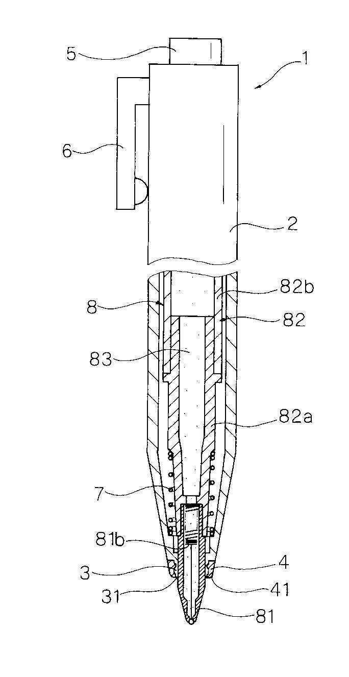
도 1은, 본 발명의 제1의 실시 형태의 펜촉 돌출 상태를 도시하는 일부 절결(切欠) 종단면도이다.
도 2는, 도 1의 요부 확대 종단면도이다.
도 3은, 본 발명의 제1의 실시 형태의 펜촉 몰입 상태를 도시하는 일부 절결 종단면도이다.
도 4는, 도 3의 요부 확대 종단면도이다.
도 5는, 제1의 실시 형태에 이용한 필기체의 종단면도이다.
도 6은, 열 변색성 잉크의 변색 거동을 도시하는 설명도이다.
도 7은, 본 발명의 제2의 실시 형태의 펜촉 돌출 상태를 도시하는 일부 절결 종단면도이다.
도 8은, 본 발명의 제3의 실시 형태의 펜촉 돌출 상태를 도시하는 일부 절결 종단면도이다.
도 9는, 본 발명의 제4의 실시 형태의 펜촉 돌출 상태를 도시하는 일부 절결 종단면도이다.
도 10은, 본 발명의 제5의 실시 형태의 펜촉 돌출 상태를 도시하는 일부 절결 종단면도이다.
도 11은, 제5의 실시 형태에 이용한 필기체의 종단면도이다.
도 12는, 본 발명의 제6의 실시 형태의 펜촉 돌출 상태를 도시하는 일부 절결 종단면도이다.
도 13은, 본 발명의 제7의 실시 형태의 펜촉 돌출 상태를 도시하는 일부 절결 종단면도이다.
도 14는, 본 발명의 제8의 실시 형태의 펜촉 돌출 상태를 도시하는 일부 절결 종단면도이다.
도 15는, 본 발명의 제9의 실시 형태의 펜촉 돌출 상태를 도시하는 일부 절결 종단면도이다.
도 16은, 본 발명의 제10의 실시 형태의 펜촉 돌출 상태를 도시하는 일부 절결 종단면도이다.
도 17은, 본 발명의 제11의 실시 형태의 펜촉 돌출 상태를 도시하는 종단면도이다.
도 18은, 본 발명의 제12의 실시 형태의 비필기 상태를 도시하는 종단면도이다.
도 19는, 도 18의 A-A선 확대 단면도이다.
도 20은, 도 18의 필기 상태를 도시하는 종단면도이다.1 is a partial cutaway longitudinal cross-sectional view showing a nib protruding state of the first embodiment of the present invention.
Fig. 2 is an enlarged longitudinal sectional view of a main portion of Fig. 1.
Fig. 3 is a partially cut longitudinal sectional view showing the immersion state of the nib of the first embodiment of the present invention.
4 is an enlarged longitudinal sectional view of a main portion of FIG. 3.
5 is a longitudinal cross-sectional view of the cursive body used in the first embodiment.
6 is an explanatory diagram showing the discoloration behavior of the thermochromic ink.
7 is a partially cutaway longitudinal sectional view showing a nib protruding state of a second embodiment of the present invention.
Fig. 8 is a partially cutaway longitudinal sectional view showing the nib protruding state of the third embodiment of the present invention.
Fig. 9 is a partially cutaway longitudinal sectional view showing a nib protruding state of a fourth embodiment of the present invention.
10 is a partially cutaway longitudinal sectional view showing a nib projecting state of a fifth embodiment of the present invention.
11 is a longitudinal cross-sectional view of the cursive body used in the fifth embodiment.
Fig. 12 is a partially cut longitudinal sectional view showing a pen tip protruding state according to a sixth embodiment of the present invention.
13 is a partially cutaway longitudinal sectional view showing a nib protruding state of a seventh embodiment of the present invention.
14 is a partially cutaway longitudinal cross-sectional view showing a pen tip protruding state according to an eighth embodiment of the present invention.
15 is a partially cutaway longitudinal sectional view showing the nib projecting state of the ninth embodiment of the present invention.
Fig. 16 is a partially cutaway longitudinal sectional view showing a nib protruding state of the tenth embodiment of the present invention.
17 is a longitudinal sectional view showing a nib protruding state of an eleventh embodiment of the present invention.
18 is a longitudinal sectional view showing a non-handwritten state of the twelfth embodiment of the present invention.
19 is an enlarged cross-sectional view taken along line AA in FIG. 18.
20 is a longitudinal sectional view showing the writing state of FIG. 18.
[실시예][Example]
<제1의 실시의 형태><First embodiment>
본 발명의 열 변색성 필기 도구의 제1의 실시의 형태를 도 1 내지 도 5에 도시한다.1 to 5 show a first embodiment of the thermochromic writing instrument of the present invention.
본 실시의 형태의 열 변색성 필기 도구(1)는, 축 통(2)과, 축 통(2) 내에 전후 방향으로 이동 가능하게 수용된 필기체(8)로 이루어진다.The
·축 통 · Shaft
상기 축 통(2)은, 경질 재료(예를 들면, 폴리카보네이트(polycarbonate) 수지)의 사출 성형에 의해 얻어진다. 상기 축 통(2)의 전단부는, 끝이 가는 모양으로 형성된다. 상기 끝이 가는 모양의 전단부의 전단(즉, 죽 통(2)의 전단)에는 전단 구멍(31)이 전후 방향으로 관통하여 설치된다. 상기 전단 구멍(31)을 통과하여 축 통(2) 내에 수용한 필기체(8)의 펜촉(81)이 출몰 가능(즉, 외부에 돌출 가능, 또한 축 통(2) 내에 몰입 가능) 해진다. 상기 축 통(2)의 뒷부분 외면에는, 포켓 등에 협지 가능한 클립(6)이 돌출하여 설치되어 있다. 또 상기 축 통(2) 내에는 필기체(8)를 상시 후방으로 가압하는 탄발체(7)(구체적으로는, 압축 코일 스프링)가 수용된다. 상기 축 통(2)은 전축(前軸)과 이 전축의 후단에 착탈이 자유롭게 나사 결합되는 후축(後軸)으로 이루어지기 때문에, 상기 축 통(2) 내에서 상기 필기체(8)를 꺼내어 교환하는 것이 가능하다.The
·펜촉 지지부· Nib support
상기 전단 구멍(31)을 구비하는 축 통(2)의 전단은, 펜촉(81)이 축 통(2)의 전단으로부터 외부로 돌출한 상태(필기시)에 있어서, 펜촉(81)의 지름 방향 외면을 지지하는 펜촉 지지부(3)로 이루어진다. 상기 펜촉 지지부(3)는 축 통(2)의 전단에 일체로 형성되기 때문에, 축 통(2)과 같은 경질 재료(예를 들면, 폴리카보네이트 수지)에 의해 구성된다.The front end of the
·마찰부· Friction
상기 축 통(2)의 전단 외면(즉, 펜촉 지지부(3)의 전단 외면)에 연질 재료(예를 들면, SBS 수지, SEBS 수지 등의 저마모성의 탄성 재료)로 이루어지는 마찰부(4)가 설치된다.A
상기 마찰부(4)는 펜촉 지지부(3)의 전단 외주면에 환형(環形)으로 설치된다. 그것에 의해, 마찰부(4)를 이용하여 마찰하기 전에 마찰부(4)의 둘레 방향의 방향을 확인하는 것이 불필요해지고, 신속하게 마찰 변색 작업을 개시할 수 있다. 또한, 상기 마찰부(4)의 형상은, 비환형(예를 들면, 둘레 방향으로 복수 분산되는 구성, 둘레 방향의 1개소에 형성되는 구성 등)이라도 좋다.The
상기 마찰부(4)의 전단 외주연(41)에는, 볼록 곡면 또는 경사면이 형성된다. 그것에 의해, 마찰 변색시, 마찰부(4)와 피필기면과의 원활한 접촉이 가능해지는 동시에, 마찰부(4)와 피필기면과의 적정한 접촉 면적이 얻어짐으로써 마찰열의 발생이 용이해진다.A convex curved surface or an inclined surface is formed on the outer
상기 마찰부(4)의 지름 방향 내면은 전단 구멍(31) 내면보다 지름 방향 외측에 위치한다. 즉, 상기 마찰부(4)는, 전단 구멍(31)의 내면보다 지름 방향 내측에 돌출되어 있지 않다. 그 때문에, 펜촉 출몰시, 상기 마찰부(4)와 축 통(2) 내에 수용된 필기체(8)(구체적으로는 펜촉(81))와의 비접촉 상태가 유지된다. 그것에 의해, 축 통(2) 내에 수용된 필기체(8)의 펜촉(81)이 출몰할 때, 필기체(구체적으로는 펜촉(81))가 마찰부(4)와 접촉하지 않고, 원활한 펜촉(810)의 출몰 작업이 얻어지고, 또한, 마찰부(4)가 잉크의 부착에 의해 오염되는 일이 없다.The inner surface of the
상기 마찰부(4)는, 축 통(2)의 전단 외면에 별도의 부품을 고착하는 것(예를 들면, 끼움식, 압입식, 나사 결합식, 접착식 등)에 의해 얻어진다. 또한, 상기 마찰부(4)는, 축 통(2)과의 2색 성형에 의해 얻어진다.The
·출몰 기구· Appearance mechanism
상기 축 통(2)에는, 펜촉을 출몰시키는 출몰 기구가 내장되어 있다. 본 실시의 형태에서는, 상기 출몰 기구로서, 소위, 후단 노크식이 채용된다. 상기 출몰 기구는, 상기 축 통(2)의 후단으로부터 후방으로 돌출된 조작부(5)를, 전방으로 압압함으로써, 필기체(8)를 후방 가압에 저항하여 전방으로 이동시키고, 펜촉 몰입 상태에서 펜촉 돌출 상태로 하는 것이다. 또한, 본 실시의 형태에서는, 다시 조작부(5)를 전방으로 압압함으로써, 펜촉 돌출 상태에서 펜촉 몰입 상태로 할 수 있다.The
·필기체·cursive
상기 필기체(8)는, 펜촉(81)과, 상기 펜촉(81)을 전단에 구비하고, 또한, 내부에 열 변색성 잉크(83)를 수용하는 잉크 수용부(82)로 이루어진다. 상기 펜촉(81)으로부터 상기 열 변색성 잉크(83)가 토출된다.The writing
상기 펜촉(81)은, 전단에 회전 가능하게 포지(抱持)된 볼(81a)을 구비하는 볼펜 팁으로 이루어진다. 상기 펜촉(81)의 내부에는, 전단의 볼(81a)을 전방으로 압압하는 탄발체(81b)가 수용된다. 상기 탄발체(81b)는, 압축 코일 스프링의 전단부에 로드(rod)부를 구비한 구성이고, 상기 로드부의 전단이 볼(81a) 후면에 접촉하고 있다. 비필기시, 상기 탄발체(81b)의 전방 가압에 의해 볼(81a)이 볼펜 팁 전단 내측의 코킹부(caulked portion) 내면에 밀접되고, 펜촉(81)의 전단으로부터의 잉크의 누출 및 잉크의 증발을 방지할 수 있다.The
상기 잉크 수용부(82)는, 펜촉(81)을 유지하는 펜촉 홀더(82a)와, 상기 펜촉 홀더(82a)가 전단에 고착되는 잉크 수용관(82b)으로 이루어진다. 상기 잉크 수용부(82) 내에는 열 변색성 잉크(82)와, 이 잉크(83)의 후단에 배치되는 추종체(84)가 수용된다.The
상기 열 변색성 잉크(83)는, 저온 측 변색점(완전 발색 온도t1)이 -30℃ 내지 -10℃의 범위의 임의의 온도에 설정되고, 고온 측 변색점(완전 소색 온도 t4)가 60℃ 내지 80℃의 범위의 임의의 온도에 설정되며, 히스테리시스폭 △H가 40℃ 내지 60℃의 범위를 나타내는 가역 열 변색성 잉크가 채용된다. 상기 열 변색성 잉크(83)는, 소색 상태에 있어서 무색이 된다.The
상기 추종체(84)는, 잉크의 소비에 따라서 전진하고, 또한 잉크의 후퇴(즉, 역류)를 방지하는 것이고, 예를 들면, 고점도 유체, 탄성 재료로 이루어지는 가동 마개, 또는 고점도 유체 속에 고체물을 수용시킨 구성 등을 예로 들 수 있다.The
상기 잉크 수용관(82b)의 후단에는, 통기 구멍을 가지는 미전(尾栓)(85)이 끼워서 부착된다.A trailing
·각도 α· Angle α
또한, 본 실시의 형태에 있어서, 상기 마찰부(4)의 외면과 돌출 상태의 펜촉(81) 전단에 접하는 접선과, 접선이 이루는 각도 α는, 15도 내지 50도의 범위에 설정된다. 그것에 의해, 마찰부(4)의 적정한 마찰 변색 성능이 얻어지는 동시에, 필기시(펜촉 돌출 시), 펜촉(81)을 용이하게 눈으로 확인할 수 있고, 또한 마찰부(4)와 피필기면과의 비접촉 상태가 유지된다.In addition, in the present embodiment, the angle α formed by the tangent line contacting the outer surface of the
·필기시(도 1 및 도 2 참조)When writing (refer to FIGS. 1 and 2)
본 실시의 형태의 열 변색성 필기 도구(1)를 한쪽 손으로 쥐고, 조작부(5)를 전방으로 압압 조작함으로써, 신속하게 펜촉 몰입 상태에서 펜촉 돌출 상태로 할 수 있다. 이 돌출 상태의 펜촉으로 지면 등의 피필기면에 필기하는 것에 의해, 열 변색성 잉크(83)에 의한 필적을 피필기면에 형성할 수 있다.By grasping the
·마찰 변색시(도 3 및 도 4 참조)· Frictional discoloration (see FIGS. 3 and 4)
필기 후, 상기 열 변색성 필기 도구(1)를 한쪽 손으로 쥔 상태에서, 열 변색성 필기 도구(1)를 크게 바꿔 쥐지 않고, 조작부(5)를 전방으로 압압 조작함으로써, 신속하게 펜촉 돌출 상태에서 펜촉 몰입 상태로 할 수 있다. 상기 펜촉 몰입 상태에 있어서, 마찰부(4)를 이용하여 피필기면에 형성된 상기 열 변색성 잉크(83)에 의한 필적을 마찰하여, 그때에 발생하는 마찰열로 상기 필적을 열 변색시킬 수 있다.After writing, in the state in which the
<제2의 실시의 형태><Second embodiment>
본 발명의 열 변색성 필기 도구의 제2의 실시의 형태를 도 7에 도시한다.7 shows a second embodiment of the thermochromic writing instrument of the present invention.
본 실시의 형태의 열 변색성 필기 도구(1)는, 제1의 실시의 형태의 변형 예이고, 제1의 실시의 형태와 다른 점은, 축 통(2)의 후단부 외주면에, 통형상의 조작부(5)를 전후 방향으로 이동 가능하게 설치한 점이다. 상기 조작부(5)의 외면에는, 포켓 등에 협지 가능한 클립(6)이 돌출 설치되어 있다.The
또한, 상기 제2의 실시의 형태에 있어서, 다른 구성 및 작용 효과는, 제1의 실시의 형태와 공통이므로 설명을 생략한다.Note that, in the second embodiment, other configurations and operational effects are the same as those in the first embodiment, and description thereof is omitted.
<제3의 실시의 형태><Third embodiment>
본 발명의 열 변색성 필기 도구의 제3의 실시의 형태를 도 8에 도시한다.8 shows a third embodiment of the thermochromic writing instrument of the present invention.
본 실시의 형태의 열 변색성 필기 도구(1)는, 제1의 실시의 형태의 변형 예이고, 제1의 실시의 형태와 다른 점은, 축 통(2)의 후단부 외주면에, 조작부(5)를 축 통(2)에 대하여 회전 가능하게 설치한 점이다. 상기 조작부(5)의 외면에는, 포켓 등에 협지 가능한 클립(6)이 돌출 설치되어 있다.The
즉, 본 실시의 형태의 출몰 기구는, 소위 회전식이고, 축 통(2)에 대하여 조작부(5)를 회전 조작함으로써, 전단 구멍(31)으로부터 펜촉(81)을 출몰시키는 것이다.That is, the opening / closing mechanism of the present embodiment is a so-called rotary type, and the
또한, 상기 제3의 실시의 형태에 있어서, 다른 구성 및 작용 효과는, 제1의 실시의 형태와 공통이므로 설명을 생략한다.Note that, in the third embodiment, other configurations and operational effects are the same as those of the first embodiment, and description thereof is omitted.
<제4의 실시의 형태><Fourth embodiment>
본 발명의 열 변색성 필기 도구의 제4의 실시의 형태를 도 9에 도시한다.Fig. 9 shows a fourth embodiment of the thermochromic writing instrument of the present invention.
본 실시의 형태의 열 변색성 필기 도구(1)는, 제1의 실시의 형태의 변형 예이고, 제1의 실시의 형태와 다른 점은, 축 통(2)의 측벽에 형성된 구멍으로부터, 조작부(5)가 지름 방향 외측으로 돌출된 점이다.The
즉, 본 실시의 형태의 출몰 기구는, 소위 사이드 노크 식이고, 상기 조작부(5)를 지름 방향 내측으로 압압 조작함으로써, 전단 구멍(31)으로부터 펜촉(81)을 출몰시키는 것이다.That is, the opening / closing mechanism of the present embodiment is a so-called side knocking type, and the
또한, 상기 제4의 실시의 형태에 있어서, 다른 구성 및 작용 효과는, 제1의 실시의 형태와 공통이므로 설명을 생략한다.Note that, in the fourth embodiment, other configurations and operational effects are common to those of the first embodiment, and thus descriptions thereof will be omitted.
<제5의 실시의 형태><Fifth embodiment>
본 발명의 열 변색성 필기 도구의 제5의 실시의 형태를 도 10 및 도 11에 도시한다.10 and 11 show a fifth embodiment of the thermochromic writing instrument of the present invention.
본 실시의 형태의 열 변색성 필기 도구(1)는, 축 통(2)과, 축 통(2) 내에 전후 방향으로 이동 가능하게 수용된 복수개의 필기체(8)로 이루어진다.The
축 통(2) 내에는, 복수개의 필기체(8)의 각각이 전후 방향(축 방향)으로 이동 가능하게 수용되어 있다. 상기 필기체(8)의 각각은, 탄발체(7)(구체적으로는 압축 코일 스프링)에 의해 후방으로 가압되어 있다.In the
상기 축 통(2)에는, 펜촉(81)을 출몰시키는 출몰 기구가 내장되어 있다. 본 실시의 형태에서는, 상기 출몰 기구로서, 소위 사이드 슬라이드 식이 채용된다. 상기 출몰 기구는, 축 통(2) 측벽으로부터 지름 방향 외측으로 돌출된 각각의 조작부(5)를, 탄발체(7)의 후방 가압에 저항하여 전방으로 압압 조작함으로써, 전단 구멍(31)으로부터 펜촉(81)을 출몰시키는 것이다. The
상기 축 통(2)은, 끝이 가는 모양의 원통체로 이루어지는 전축(前軸)(2a)과, 이 전축(2a)의 후단부와 나사 결합 또는 압입에 의해 부착되는 원통형의 탄발체 지지부(2b)와, 이 탄발체 지지부(2b)의 후단부와 나사 결합 또는 압입에 의해 부착되는 원통형의 후축(後軸)(2c)으로 이루어진다.The
상기 전축(2a)의 전단에는, 필기체(8)의 각각이 택일적으로 돌출 가능한 전단 구멍(31)이 축 방향으로 관통 설치된다.At the front end of the
상기 후축(2c)의 뒷부분의 측벽에는, 축 통(2) 내에 수용하는 필기체(8)의 개수에 따른 복수(여기서는 2개)의 전후 방향으로 뻗는 가늘고 긴 모양의 창문 구멍(21)이, 지름 방향으로 관통 설치된다. 또 상기 후축(2c)의 창문 구멍(21)의 상호 간의 측벽 내면에는, 전후 방향으로 뻗는 리브(rib)로 이루어지는 계지 벽부(22)가 형성되고, 상기 계지 벽부(22)에 펜촉(81)이 돌출되었을 때의 그 돌출된 펜촉(81)에 대응한 조작체(9)의 후단이 계지된다. 상기 후축(2c)의 후단벽 내면에는, 접촉 벽부(23)가 형성되고, 상기 접촉 벽부(23)에, 펜촉(81)이 몰입되었을 때의 그 몰입된 펜촉(81)에 대응한 조작체(9)의 후단이 계지된다.On the side wall of the rear portion of the
상기 필기체(8)의 각각은, 볼펜 리필이고, 전단에 볼(81a)이 회전 가능하게 포지(抱持)된 펜촉(81)과, 이 펜촉(81)을 전단에 구비하고, 또한 후단이 개구된 잉크 수용관(82b)으로 이루어진다. 상기 잉크 수용관(82b)의 내부에는, 전단 감점성을 가지는 수성 겔로 이루어지는 열 변색성 잉크가 수용된다. 상기 잉크 수용관(82b) 내의 열 변색성 잉크(83)의 후단에는, 이 잉크(83)의 소비에 따라서 전진하는 고점도 유체로 이루어지는 추종체(84)가 충전된다.Each of the writing
상기 펜촉(81)의 각각은, 전단에 회전 가능하게 포지된 볼(81a)을 구비하는 볼펜 팁으로 이루어진다. 상기 펜촉(81)의 각각의 내부에는, 전단의 볼(81a)을 전방으로 압압하는 탄발체(81b)가 수용된다. 상기 탄발체(81b)는, 압축 코일 스프링의 전단부에 로드부를 구비한 구성이고, 상기 로드부의 전단이 볼(81) 후면에 접촉하고 있다. 비필기시, 상기 탄발체(81b)의 전방 가압에 의해 볼(81a)이 볼펜 팁 전단의 내측의 전단 테두리부내면에 밀접되며, 펜촉(81)의 각각의 전단에서의 잉크의 누출 및 잉크의 증발을 방지할 수 있다. 또 펜촉(81)은, 잉크 수용관(82b)의 전단 개구부에 압입 등에 의해 직접 부착해도 되지만, 본 실시의 형태에서는 펜촉 홀더(82a)를 개재하여 잉크 수용관(82b)의 전단 개구부에 고착된다.Each of the
상기 열 변색성 잉크(83)의 각각은, 저온 측 변색점(완전 발색 온도 t1)이-30℃ 내지 -10℃의 범위의 임의의 온도에 설정되고, 고온 측 변색점(완전 소색 온도 t4)이 60℃ 내지 80℃의 임의의 온도에 설정되며, 히스테리시스폭 △H가 40℃ 내지 60℃의 범위를 나타내는 가역 열 변색성 조성물을 가지는 잉크가 채용된다. 상기 열 변색성 잉크(83)의 각각은, 발색 상태에 있어서, 예를 들면, 흑색, 청색, 적색, 황색, 녹색, 갈색, 자색, 감색, 분홍색, 밝은 청색 등을 나타낸다. 상기 열 변색성 잉크(83)의 각각은, 소색 상태에 있어서, 무색이 된다. 상기 열 변색성 잉크(83)의 각각은, 발색 상태에 있어서 다른 색을 나타낸다.Each of the
상기 필기체(8)의 각각의 후단에는, 조작체(9)가 부착된다. 상기 각각의 조작체(9)는 후단부에 형성되고, 또한 축 통(2)의 창문 구멍(21)으로부터 외부로 돌출하는 조작부(5)와, 이 조작부(5)의 반대 측에 설치되는 뒤쪽 돌출부(91)와, 이 조작부(5)의 반대 측의 뒤쪽 돌출부(91)의 전방에 설치되는 앞쪽 돌출부(92)와, 전단부에 형성되고, 또한 잉크 수용관(82b)의 후단 개구부에 끼워 넣어지는 감입부(嵌入部)(93)와, 이 감입부(93)의 후방에 형성되는 턱부(94)를 구비한다. 상기 감입부(93)는, 잉크 수용관(82b)의 후단 개구부에 끼워 넣어질 때, 잉크 수용관(82b)의 후단 개구부를 완전하게는 덮지않고, 잉크 수용관(82b)의 내부와 외부를 통기 가능하게 한다. 또 상기 턱부(94)의 전면에는, 탄발체(7)의 후단이 계지된다.An
필기체(8)의 펜촉(81)중 어느 하나가 몰입 상태일 때, 그 펜촉 몰입 상태의 필기체(8)에 부착된 조작체(9)의 후단부는, 축 통(2)의 후단부 내벽에 형성된 접촉 벽부(23)에 접촉된다. 한편, 필기체(8)의 펜촉(81)중 어느 하나가 돌출 상태일 때, 그 펜촉 돌출 상태의 필기체(8)에 부착된 조작체(9)의 후단부는, 축 통(2)의 내벽에 형성된 계지 벽부(22)에 계지된다.When any one of the
펜촉 몰입 상태에 있는 필기체(8)의 후단에 연결된 조작체(9)의 앞쪽 돌출부(92)는, 그 조작체(9)의 조작부(5)를 전방으로 슬라이드 조작했을 때, 먼저 펜촉 돌출 상태에 있는 필기체(8)의 후단에 연결된 조작체(9)의 뒤쪽 돌출부(91)와 접촉되고, 필기체(8)의 펜촉 돌출 상태가 해제된다.The
축 통(2)의 내벽(즉, 후축(2c)의 전단부 내면)에는, 원통형의 탄발체 지지부(2b)가 고착된다. 상기 탄발체 지지부(2b)는, 원판형의 지지 벽부를 구비하고, 필기체(8)가 삽입되는 복수(여기서는 2개)의 내측 구멍이 축 방향으로 관통 설치된다. 상기 탄발체 지지부(2b)의 후면(즉, 지지 벽부의 후면)과, 각각의 조작체(9)의 턱부(94)의 전면과의 사이에는, 각각의 탄발체(7)가 배치된다. 상기 각각의 탄발체(7)의 내부에 필기체(8)의 각각이 움직이기 쉽게 삽입되는 동시에, 각각의 탄발체(7)의 전단이 탄발체 지지부(2b)의 후면에 의해 계지되며, 각각의 탄발체(7)의 후단이 조작체(9)의 턱부(94)의 전면에 계지된다.On the inner wall of the shaft cylinder 2 (that is, the inner surface of the front end portion of the
상기 탄발체 지지부(2b)의 전면(즉, 지지 벽부의 전면)에는 통형상부가 전방으로 연장 설치되고, 그 통형상부 내면과 전축(2a)의 후단부 외면이 나사 결합 또는 압입에 의해 부착된다.On the front surface (that is, the front surface of the support wall portion) of the elastic
상기 각각의 탄발체(7)는, 각각의 조작체(9)를, 항상 후방으로 가압하고 있다. 상기 각각의 탄발체(7)는, 펜촉 돌출 상태, 펜촉 몰입 상태 중 어느 하나에 있어서도 압축 상태(즉, 필기체(8)가 후방으로 가압 된 상태)에 있고, 그것에 의해, 각각의 조작체(9)의 전후의 불균일한 움직임이 방지된다.Each of the above-described
축 통(2)의 전단부 외면(즉, 전축(2a)의 전단부 외면)에는, 연질 재료(예를 들면, SBS 수지, SEBS 수지 등의 저마모성의 탄성 재료)로 이루어지는 마찰부(4)가 형성된다. 상기 마찰부(4)는, 축 통(2) 외면에, 2색 성형, 끼워 맞춤식, 압입식, 나사 결합식, 접착식 등의 수단에 의해 고착된다.On the outer surface of the front end portion of the shaft cylinder 2 (that is, the outer surface of the front end portion of the
본 실시의 형태의 열 변색성 필기 도구(1)를 한쪽 손에 쥐고, 하나의 조작부(5)를 전방으로 압압 조작함으로써, 신속하게 펜촉 몰입 상태에서 펜촉 돌출 상태로 할 수 있다. 이 돌출 상태의 펜촉으로, 지면 등의 피필기면에 필기하는 것에 의해, 열 변색성 잉크(83)에 의한 필적을 피필기면에 형성할 수 있다.By holding the
필기 후, 상기 열 변색성 필기 도구(1)를 한쪽 손에 쥔 상태로, 열 변색성 필기 도구(1)를 크게 바꿔 쥐지 않고, 다른 조작부(5)(즉, 펜촉 몰입 상태에 있는 필기체(8)에 연결된 조작체(9))를 전방으로 압압 조작함으로써, 신속하게 펜촉 돌출 상태에서 펜촉 몰입 상태로 할 수 있다. 이 펜촉 몰입 상태에 있어서의 마찰부(4)에서, 피필기면에 형성된 상기 열 변색성 잉크(83)에 의한 필적을 마찰하여, 그때에 발생하는 마찰열로 상기 필적을 열 변색시킬 수 있다.After writing, the
또한, 상기 제5의 실시의 형태에 있어서, 다른 구성 및 작용 효과는, 제1의 실시의 형태와 공통이므로 설명을 생략한다.Note that, in the fifth embodiment, other configurations and operational effects are common to the first embodiment, and thus descriptions thereof will be omitted.
<제6의 실시의 형태><The sixth embodiment>
본 발명의 열 변색성 필기 도구의 제6의 실시의 형태를 도 12에 도시한다.12 shows a sixth embodiment of the thermochromic writing instrument of the present invention.
본 실시의 형태의 열 변색성 필기 도구(1)는, 제2의 실시의 형태의 변형 예이며, 조작부(5)의 후단 외면에 연질 재료(예를 들면, SBS 수지, SEBS 수지 등의 저마모성의 탄성 재료)로 이루어지는 마찰부(4)를 설치한 점이, 상기 제2의 실시의 형태와 다르다.The
본 실시의 형태의 열 변색성 필기 도구(1)는, 상기 조작부(5)의 외주면에, 상기 마찰부(4)를 이용하여 마찰할 때에 파지 가능한 파지부(51)가 설치된다. 그것에 의해, 마찰 변색시, 안정된 파지가 가능해진다. 상기 파지부(51)는, 축 방향의 길이가 10㎜이상(바람직하게는, 15㎜ 이상)으로 설정된다. 또 본 실시의 형태의 열 변색성 필기 도구(1)는, 조작부(5)의 후단 외면에 연질 재료로 이루어지는 마찰부(4)를 설치함으로써, 조작부(5)를 전방으로 압압 조작할 때의 손가락과의 미끄럼 방지가 이루어진다.In the
본 실시의 형태의 열 변색성 필기 도구(1)를 이용하여 필기한 후, 상기 열 변색성 필기 도구(1)의 조작부(5)의 파지부(51)를 파지하고, 마찰부(4)에서, 피필기면에 형성된 상기 열 변색성 잉크(83)에 의한 필적을 마찰하여, 그때에 발생하는 마찰열로 상기 필적을 열 변색시킬 수 있다. 그것에 의해, 본 실시의 형태의 열 변색성 필기 도구(1)는, 상기 마찰 변색할 때, 펜촉(81)을 축 통(2) 내에 몰입시키는 것이 불필요해지고, 펜촉 돌출 상태, 펜촉 몰입 상태 중의 어떤 상태에서도 마찰 변색 가능하다.After writing using the
또한, 상기 제6의 실시의 형태에 있어서, 다른 구성 및 작용 효과에 대해서는, 제1 및 제2의 실시의 형태와 공통이므로 설명을 생략한다.In addition, in the sixth embodiment, other configurations and operational effects are the same as those of the first and second embodiments, and description thereof will be omitted.
<제7의 실시의 형태><7th embodiment>
본 발명의 열 변색성 필기 도구의 제7의 실시의 형태를 도 13에 도시한다.Fig. 13 shows a seventh embodiment of the thermochromic writing instrument of the present invention.
본 실시의 형태의 열 변색성 필기 도구(1)는, 제3의 실시의 형태의 변형 예이고, 조작부(5)의 후단 외면에 연질 재료(예를 들면, SBS 수지, SEBS 수지 등의 저마모성의 탄성 재료)로 이루어지는 마찰부(4)를 설치한 점이, 상기 제3의 실시의 형태와 다르다.The
본 실시의 형태의 열 변색성 필기 도구(1)는, 상기 조작부(5)의 외주면에, 상기 마찰부(4)를 이용하여 마찰할 때에 파지 가능한 파지부(51)가 설치된다. 그것에 의해, 마찰 변색시, 안정된 파지가 가능해진다. 상기 파지부(51)는, 축 방향의 길이가 10㎜이상(바람직하게는, 15㎜ 이상)으로 설정된다.In the
본 실시의 형태의 열 변색성 필기 도구(1)를 이용하여 필기한 후, 상기 열 변색성 필기 도구(1)의 조작부(5)의 파지부(51)를 파지하고, 마찰부(4)에서, 피필기면에 형성된 상기 열 변색성 잉크(83)에 의한 필적을 마찰하여, 그때에 발생하는 마찰열로 상기 필적을 열 변색시킬 수 있다. 그것에 의해, 본 실시의 형태의 열 변색성 필기 도구(1)는, 상기 마찰 변색할 때, 펜촉(81)을 축 통(2) 내에 몰입시키는 것이 불필요해지고, 펜촉 돌출 상태, 펜촉 몰입 상태중 어떤 상태에서도 마찰 변색 가능하다.After writing using the
또한, 상기 제7의 실시의 형태에 있어서, 다른 구성 및 작용 효과에 대해서는, 제1 및 제3의 실시의 형태와 공통이므로 설명을 생략한다.In addition, in the seventh embodiment, other configurations and operational effects are the same as those of the first and third embodiments, and description thereof is omitted.
<제8의 실시의 형태><Eighth embodiment>
본 발명의 열 변색성 필기 도구의 제8의 실시의 형태를 도 14에 도시한다.14 shows an eighth embodiment of the thermochromic writing instrument of the present invention.
본 실시의 형태의 열 변색성 필기 도구(1)는, 제4의 실시의 형태의 변형 예이고, 축 통(2)의 후단 외면에 연질 재료(예를 들면, SBS 수지, SEBS 수지 등의 저마모성의 탄성 재료)로 이루어지는 마찰부(4)를 설치한 점이, 상기 제4의 실시의 형태와 다르다.The
본 실시의 형태의 열 변색성 필기 도구(1)는, 조작부(5)를 마찰부(4)에 대하여 독립하여 설치할 수 있고, 조작부(5)의 외관이나 크기를 자유롭게 설정할 수 있다. 또 본 실시의 형태의 열 변색성 필기 도구(1)는, 마찰 변색시, 축 통(2)의 뒷부분을 파지함으로써, 안정된 파지가 가능해진다.The
본 실시의 형태의 열 변색성 필기 도구(1)를 이용하여 필기한 후, 상기 열 변색성 필기 도구(1)의 축 통(2) 뒷부분을 파지하고, 마찰부(4)에서, 피필기면에 형성된 상기 열 변색성 잉크(83)에 의한 필적을 마찰하여, 그때에 발생하는 마찰열로 상기 필적을 열 변색시킬 수 있다. 그것에 의해, 본 실시의 형태의 열 변색성 필기 도구(1)는, 상기 마찰 변색할 때, 펜촉(81)을 축 통(2) 내에 몰입시키는 것이 불필요해지고, 펜촉 돌출 상태, 펜촉 몰입 상태중 어떤 상태에서도 마찰 변색 가능하다.After writing using the
또한, 상기 제8의 실시의 형태에 있어서, 다른 구성 및 작용 효과에 대해서는, 제1 및 제4의 실시의 형태와 공통이므로 설명을 생략한다.In addition, in the eighth embodiment, other configurations and operational effects are common to those of the first and fourth embodiments, and thus descriptions thereof will be omitted.
<제9의 실시의 형태><The ninth embodiment>
본 발명의 열 변색성 필기 도구의 제9의 실시의 형태를 도 15에 도시한다.15 shows a ninth embodiment of the thermochromic writing instrument of the present invention.
본 실시의 형태의 열 변색성 필기 도구(1)는, 제5의 실시의 형태의 변형 예이고, 축 통(2)의 외면에 연질 재료(예를 들면, SBS 수지, SEBS 수지 등의 저마모성의 탄성 재료)로 이루어지는 마찰부(4)를 설치한 점이, 상기 제5의 실시의 형태와 다르다.The
본 실시의 형태의 열 변색성 필기 도구(1)는, 조작부(5)를 마찰부(4)에 대하여 독립하여 설치할 수 있고, 조작부(5)의 외관이나 크기를 자유롭게 설정할 수 있다. 또 본 실시의 형태의 열 변색성 필기 도구(1)는, 마찰 변색시, 축 통(2)의 뒷부분을 파지함으로써, 안정된 파지가 가능해진다.The
본 실시의 형태의 열 변색성 필기 도구(1)를 이용하여 필기한 후, 상기 열 변색성 필기 도구(1)의 축 통(2) 뒷부분을 파지하고, 마찰부(4)에서, 피필기면에 형성된 상기 열 변색성 잉크(83)에 의한 필적을 마찰하여, 그때에 발생하는 마찰열로 상기 필적을 열 변색시킬 수 있다. 그것에 의해, 본 실시의 형태의 열 변색성 필기 도구(1)는, 상기 마찰 변색할 때, 펜촉(81)을 축 통(2) 내에 몰입시키는 것이 불필요해지고, 펜촉 돌출 상태, 펜촉 몰입 상태중 어떤 상태에서도 마찰 변색 가능하다.After writing using the
또한, 상기 제9의 상태에 있어서, 다른 구성 및 작용 효과에 대해서는, 제1 및 제5의 실시의 형태와 공통이므로 설명을 생략한다.Note that, in the ninth state, other configurations and operational effects are common to those of the first and fifth embodiments, and thus explanations are omitted.
<제10의 실시의 형태><The tenth embodiment>
본 발명의 열 변색성 필기 도구의 제10의 실시의 형태를 도 16에 도시한다.16 shows a tenth embodiment of the thermochromic writing instrument of the present invention.
본 실시의 형태의 열 변색성 필기 도구(1)는, 제8의 실시의 형태의 변형 예이며, 마찰부 조작부(2d)를 축 통(2)의 외면에 설치하고, 상기 마찰부 조작부(2d)를 회전 조작함으로써, 마찰부(4)를 축 통(2)의 후단으로부터 출몰 가능하게 구성한 점이, 상기 제5의 실시의 형태와 다르다. The
본 실시의 형태의 열 변색성 필기 도구(1)는, 마찰시에는, 마찰부(4)를 축 통(2)의 후단으로부터 외부로 돌출시켜서 마찰에 사용할 수 있고, 한편, 비필기시나 보관시에는, 마찰부(4)를 축 통(2) 내에 몰입시켜서 마찰부(4)의 오염을 방지할 수 있다.The
본 실시의 형태의 열 변색성 필기 도구(1)를 이용하여 필기한 후, 상기 열 변색성 필기 도구(1)의 축 통(2) 뒷부분을 파지하고, 마찰부 조작부(2d)를 축 통(2)에 대하여 회전 조작함으로써, 마찰부(4)를 축 통(2)의 후단으로부터 외부로 돌출시키고, 그 돌출 상태의 마찰부(4)에서, 피필기면에 형성된 상기 열 변색성 잉크(83)에 의한 필적을 마찰하여, 그때에 발생하는 마찰열로 상기 필적을 열 변색시킬 수 있다. 본 실시의 형태의 열 변색성 필기 도구(1)는, 상기 마찰 변색할 때, 펜촉(81)을 축 통(2) 내에 몰입시키는 것이 불필요해지고, 펜촉 돌출 상태, 펜촉 몰입 상태중 어떤 상태에서도 마찰 변색 가능하다.After writing using the
또한, 상기 제10의 실시의 형태에 있어서, 다른 구성 및 작용 효과에 대해서는, 제1 및 제5의 실시의 형태와 공통이므로 설명을 생략한다.In addition, in the tenth embodiment, descriptions of other structures and effects are omitted since they are common to the first and fifth embodiments.
<제11의 실시의 형태><Eleventh embodiment>
본 발명의 열 변색성 필기 도구(1)의 제11의 실시의 형태를 도 17에 도시한다.17 shows an eleventh embodiment of the
본 실시의 형태의 열 변색성 필기 도구(1)는, 제2의 실시의 형태의 변형 예이고, 축 통(2)의 전단 외면에 마찰부(4)를 설치하는 동시에, 조작부(5)의 후단 외면에 연질 재료(예를 들면, SBS 수지, SEBS 수지 등의 저마모성의 탄성 재료)로 이루어지는 마찰부(4)를 설치한 점이, 상기 제2의 실시의 형태와 다르다. 상기 조작부(5)의 후단 외면에 설치한 마찰부(4)는, 외면에 볼록 곡면을 구비한다. 상기 축 통(2)의 전단 외면에 설치한 마찰부(4)와, 상기 조작부(5)의 후단 외면에 설치한 마찰부(4)는, 형상이 다르고, 마찰시의 피필기면과의 접촉 면적의 크기가 다르다.The
본 실시의 형태의 열 변색성 필기 도구(1)는, 조작부(5)의 후단 외면에 설치한 마찰부(4)를 이용하여 마찰할 때에 파지 가능한 파지부(51)가, 상기 조작부(5)의 외주면에 설치된다. 그것에 의해, 마찰 변색시, 안정된 파지가 가능해진다. 상기 파지부(51)는, 축 방향의 길이가 10㎜이상(바람직하게는, 15㎜ 이상)으로 설정된다. 또 본 실시의 형태의 열 변색성 필기 도구(1)는, 조작부(5)의 후단 외면에 연질 재료로 이루어지는 마찰부(4)를 설치함으로써, 조작부(5)를 전방으로 압압 조작할 때의 손가락과의 미끄럼 방지가 이루어진다.In the
본 실시의 형태의 열 변색성 필기 도구(1)를 이용하여 필기한 후, 상기 열 변색성 필기 도구(1)의 조작부(5)의 파지부(51)를 파지하고, 조작부(5)의 후단 외면에 설치한 마찰부(5)에서, 피필기면에 형성된 상기 열 변색성 잉크(83)에 의한 필적을 마찰하여, 그때에 발생하는 마찰열로 상기 필적을 열 변색시킬 수 있다. 그것에 의해, 본 실시의 형태의 열 변색성 필기 도구(1)는, 상기 마찰 변색할 때, 펜촉(81)을 축 통(2) 내에 몰입시키는 것이 불필요해지고, 펜촉 돌출 상태, 펜촉 몰입 상태중 어떤 상태에서도 마찰 변색 가능하다.After writing using the
또 본 실시의 형태의 열 변색성 필기 도구(1)를 이용하여 필기한 후, 펜촉 몰입 상태로 하고, 축 통(2)의 전단 외면에 설치한 마찰부(4)를 이용하여, 피필기면에 형성된 상기 마찰 변색성 잉크(83)에 의한 필적을 마찰하여, 그때에 발생하는 마찰열로 상기 필적을 열 변색시킬 수 있다.In addition, after writing using the
또한, 상기 제11의 실시의 형태에 있어서, 다른 구성 및 작용 효과에 대해서는, 제1 및 제2의 실시의 형태와 공통이므로 설명을 생략한다.Note that, in the eleventh embodiment, other configurations and operational effects are common to the first and second embodiments, and description thereof will be omitted.
<제12의 실시의 형태><Twelfth embodiment>
본 발명의 열 변색성 필기 도구의 제12의 실시의 형태를 도 18 내지 도 20에 도시한다.18 to 20 show a twelfth embodiment of the thermochromic writing instrument of the present invention.
본 실시의 형태의 열 변색성 필기 도구(1)는, 제5의 실시의 형태의 변형 예이며, 제5의 실시의 형태와 다른 점은, 축 통(2)의 전단부 및 축 통(2)의 후단부에 착탈이 자유로운 캡(11)을 설치한 점이다.The
상기 탄발체 지지부(2b)의 전면(즉, 지지 벽부의 전면)과, 전축(2a)의 후단에 의해, 탄성 재료로 이루어지는 원판형의 시일(seal)체(10)가 협지 고정된다. 상기 시일체(10)는 전축(2a)의 후단과 환상(環狀)으로 밀접된다. 상기 시일체(10)는, 복수(여기서는 2개)의 구멍이 관통 설치되고, 상기 구멍의 내주면과 각각의 필기체(8)의 외주면이 환상으로 밀접 슬라이딩 된다. 상기 구멍이, 필기체(8)의 각각의 외면과 밀접 슬라이딩하는 시일부(101)를 구성한다.A disc-shaped
캡(11)은, 비필기시 또는 보관시, 축 통(2)의 전단부의 외면에 장착된다. 캡(11)을 축 통(2)의 전단부의 외면에 장착했을 때, 캡(11) 내면이, 축 통(2)의 전단부의 외면과 환상으로 밀접하고, 그것에 의해, 축 통(2)의 전단 구멍(31)이 밀폐된다. 필기시, 캡(11)을 축 통(2)의 전단부로부터 제거하고, 캡(11)을 축 통(2)의 후단부 외면에 장착하여 캡(11)의 분실을 방지할 수 있다.The
캡(11)의 머리부 외면, 축 통(2)의 전단부 외면(즉, 전축(2a)의 전단부 외면), 및 축 통(2)의 후단부 외면(즉, 후축(2c)의 후단부 외면)에는, 마찰부(4)가 형성된다. 상기 마찰부(4)는, 마찰시에 마모가루가 거의 발생하지 않는 저마모성의 탄성 재료(예를 들면, SBS 수지, SEBS 수지)로 이루어지는 마찰부(4)가 형성된다. 상기 마찰부(4)는, 캡(11) 외면 및 축 통(2) 외면에, 2색 성형, 끼워 맞춤식, 압입식, 나사 결합식, 접착식 등의 수단에 의해 고착된다.The outer surface of the head of the
또한, 상기 제12의 실시의 형태에 있어서, 다른 구성 및 작용 효과에 대해서는, 제1 및 제5의 실시의 형태와 공통이므로 설명을 생략한다.In addition, in the twelfth embodiment, descriptions of other structures and effects are omitted because they are common to the first and fifth embodiments.
본 발명을 상세하게 또 특정한 실시 형태를 참조하여 설명하였지만, 본 발명의 정신과 범위를 일탈하지 않고 여러 가지 변경이나 수정을 가할 수 있는 것은 당업자에게 있어서 명백하다.Although the present invention has been described in detail with reference to specific embodiments, it is apparent to those skilled in the art that various changes and modifications can be made without departing from the spirit and scope of the present invention.
본 출원은, 2007년 2월 26일 출원한 일본 특허 출원(특원 2007-046226), 2007년 7월 21일 출원한 일본 특허 출원(특원 2007-190261), 2008년 1월 15일 출원한 일본 특허 출원(특원 2008-005267)에 근거하는 것으로서, 그 내용은 여기에 참조하여 포함한다.This application is for Japanese patent applications filed on February 26, 2007 (Japanese Patent Application No. 2007-046226), Japanese patent application filed for July 21, 2007 (Japanese Patent Application No. 2007-190261), and Japanese patent filed for January 15, 2008 Based on the application (Patent Application 2008-005267), the contents of which are incorporated herein by reference.
1…열 변색성 필기 도구
2…축 통
2a…전축(前軸)
2b…탄발체 지지체
2c…후축(後軸)
2d…마찰부 조작부
21…창문 구멍
22…계지 벽부
23…접촉 벽부
3…펜촉 지지부
31…전단 구멍
4…마찰부
41…전단 외주연
5…조작부
51…파지부
6…클립
7…탄발체
8…필기체
81…펜촉
81a…볼
81b…탄발체
82…잉크 수용부
82a…펜촉 홀더
82b…잉크 수용관
83…잉크
84…추종체
85…미전(尾栓)
9…조작부
91…뒤쪽 돌출부
92…앞쪽 돌출부
93…감입부(嵌入部)
94…턱부
10…시일(seal)체
101…시일(seal)부
11…캡One…
2a ... 2b… Carbon support
2c ...
21…
23… Contact wall
3…
4…
5…
6…
8…
81a ...
82…
82b ...
84…
9…
92…
94…
101…
Claims (27)
축통과;
상기 축통 내에서 전후방향으로 이동하게 수용되는 필기체와;
조작부를; 구비하고,
상기 필기체의 펜촉을 상기 조작부에 의해 축 통의 전단 구멍에서 출몰 가능하게 구성하고, 상기 필기체의 내부에 열 변색성 잉크를 수용하며, 상기 필기체의 전단에 상기 열 변색성 잉크가 토출 가능한 펜촉을 설치하고, 상기 축 통의 외면에, 상기 열 변색성 잉크의 필적을 마찰하여 그때에 발생하는 마찰열로 이 필적을 열 변색 가능하게 하는 마찰부를 설치한 것을 특징으로 하는 열 변색성 필기 도구.As a thermochromic writing tool with built-in thermochromic ink,
Axial passing;
A writing body accommodated to move in the front-rear direction within the shaft;
Operation unit; Equipped,
The nib of the cursive body is configured to be able to appear and exit from the front end hole of the shaft by the manipulation unit, accommodates a thermochromic ink inside the cursive body, and installs a nib capable of discharging the thermochromic ink at the front end of the cursive body. And, on the outer surface of the shaft cylinder, a thermal discoloration writing tool, characterized in that a friction portion that rubs the handwriting of the thermochromic ink and makes this handwriting heat discolorable by the frictional heat generated at that time.
상기 마찰부를 축 통의 전단에 설치하고, 펜촉 몰입 상태에서, 마찰부 전단이 펜촉 전단에서 전방에 위치하고, 펜촉 돌출 상태에서 펜촉 전단이 마찰부 전단에서 전방에 위치하는 것을 특징으로 하는 열 변색성 필기 도구.According to claim 1,
Thermal discoloration writing, characterized in that the friction portion is installed at the front end of the shaft, and in the immersion of the nib, the front end of the friction portion is located in front of the tip of the nib, and the tip of the pen tip is located in front of the friction portion in the state of protrusion of the nib. tool.
상기 전단 구멍을 가지는 축 통의 펜촉 지지부가 경질 재료로 이루어지고, 상기 축 통의 펜촉 지지부의 전단 외면에 연질 재료로 이루어지는 마찰부를 설치한 것을 특징으로 하는 열 변색성 필기 도구.According to claim 2,
A thermochromic writing tool, characterized in that the nib support portion of the shaft cylinder having the shear hole is made of a hard material, and a friction portion made of a soft material is provided on the outer surface of the tip portion of the nib support portion of the shaft cylinder.
상기 마찰부와 상기 필기체가 비접촉 상태로 유지되는 것을 특징으로 하는 열 변색성 필기 도구.According to claim 2,
A thermochromic writing tool, characterized in that the friction portion and the writing body are kept in a non-contact state.
상기 마찰부의 전단 외주연이 볼록 곡면 또는 경사면으로 이루어지는 것을 특징으로 하는 열 변색성 필기 도구.According to claim 2,
Thermal discoloration writing tool, characterized in that the outer peripheral edge of the front end of the friction portion is made of a convex curved surface or an inclined surface.
상기 마찰부의 외면과 펜촉 돌출 상태의 펜촉 전단에 접하는 접선과, 축선이 이루는 각도를 10도 내지 60도의 범위에 설정한 것을 특징으로 한 열 변색성 필기 도구.According to claim 2,
A thermochromic writing tool, characterized in that an angle formed by a tangential line and an axial line contacting the outer surface of the friction portion and the tip of the nib in the nib protruding state is set in a range of 10 degrees to 60 degrees.
상기 마찰부를 환상(環狀)으로 설치하는 것을 특징으로 하는 열 변색성 필기 도구.According to claim 2,
A thermochromic writing tool, characterized in that the friction portion is provided in an annular shape.
상기 조작부를 축 통의 후단부에 설치하고, 상기 조작부를 전방으로 압압 조작함으로써 펜촉 몰입 상태에서 펜촉 출몰 상태로 하는 출몰 기구를 구비하는 것을 특징으로 하는 열 변색성 필기 도구.According to claim 2,
A thermochromic writing tool, characterized in that it is provided with a dispensing mechanism that is provided in the nib immersion state by immersing the nib by installing the operation unit at the rear end of the shaft cylinder and pressing the operation unit forward.
상기 조작부를 축 통의 측벽으로부터 지름 방향 외측으로 돌출시키고, 상기 조작부를 전방으로 압압 조작함으로써 펜촉 몰입 상태에서 펜촉 돌출 상태로 하는 출몰 기구를 구비하는 것을 특징으로 하는 열 변색성 필기 도구.According to claim 2,
A thermochromic writing tool, comprising: a protruding mechanism that protrudes the operation portion outward from the side wall of the shaft cylinder in the radial direction, and presses the operation portion forward, thereby turning the pen tip into a nib protrusion state.
상기 조작부를 축 통의 측벽으로부터 지름 방향 외측으로 돌출시키고, 상기 조작부를 지름 방향 내측으로 압압 조작함으로써 펜촉 몰입 상태에서 펜촉 돌출 상태로 하는 출몰 기구를 구비하는 것을 특징으로 하는 열 변색성 필기 도구.According to claim 2,
A thermochromic writing tool, comprising: a protruding mechanism that protrudes the operating portion from the side wall of the shaft cylinder in the radial direction outwards, and presses the operating portion in the radial direction to bring the pen tip into a nib protrusion state.
축 통의 뒷부분에 조작부를 설치하고, 상기 조작부를 축 통의 앞 부분에 대하여 회전 조작함으로써 펜촉을 출몰시키는 출몰 기구를 구비하는 것을 특징으로 하는 열 변색성 필기 도구.According to claim 2,
A thermochromic writing tool, comprising: an opening / closing mechanism for mounting the operation portion on the rear portion of the shaft cylinder, and rotating the operation portion with respect to the front portion of the shaft cylinder to open and close the nib.
상기 마찰부를 축 통의 후단에 설치한 것을 특징으로 하는 열 변색성 필기 도구.According to claim 1,
A thermochromic writing tool, characterized in that the friction portion is provided at the rear end of the shaft cylinder.
축 통의 후단부에 조작부를 설치하고, 상기 조작부를 축 통의 앞 부분에 대해 전방으로 압압 조작함으로써 펜촉 몰입 상태에서 펜촉 돌출 상태로 하는 출몰 기구를 구비하며, 상기 조작부의 후단 외면에 마찰부를 설치하고, 상기 조작부의 외주면에 상기 마찰부를 이용하여 마찰할 때에 파지 가능한 파지부를 설치한 것을 특징으로 하는 열 변색성 필기 도구.The method of claim 12,
An operation unit is provided at the rear end of the shaft cylinder, and a pressing mechanism is provided to press the front end of the shaft cylinder against the front portion of the shaft cylinder to bring the pen tip into a nib protruding state. And a gripping part capable of being gripped when rubbing using the friction part on an outer circumferential surface of the manipulation part.
축 통의 뒷부분에 조작부를 설치하고, 상기 조작부를 축 통의 앞 부분에 대해 회전 조작함으로써 펜촉 몰입 상태에서 펜촉 돌출 상태로 하는 출몰 기구를 구비하며, 상기 조작부의 후단 외면에 마찰부를 설치하고, 상기 조작부의 외주면에 상기 마찰부를 이용하여 마찰할 때에 파지 가능한 파지부를 설치한 것을 특징으로 하는 열 변색성 필기 도구.The method of claim 12,
An operation unit is provided at the rear portion of the shaft cylinder, and a rotation mechanism is provided to the pen nib protruding state in the nib immersion state by rotating the operation unit with respect to the front portion of the shaft cylinder, and a friction unit is provided on an outer surface of the rear end of the operation unit. A thermochromic writing tool, characterized in that a gripping part capable of being gripped is provided on the outer circumferential surface of the operation portion using the friction part.
상기 조작부를 축 통의 측벽으로부터 지름 방향 외측으로 돌출시키고, 상기 조작부를 전방으로 압압 조작함으로써 펜촉 몰입 상태에서 펜촉 돌출 상태로 하는 출몰 기구를 구비하는 것을 특징으로 하는 열 변색성 필기 도구.The method of claim 12,
A thermochromic writing tool, comprising: a protruding mechanism that protrudes the operation portion outward from the side wall of the shaft cylinder in the radial direction, and presses the operation portion forward, thereby turning the pen tip into a nib protrusion state.
상기 조작부를 축 통의 측벽으로부터 지름방향 외측으로 돌출시키고, 상기 조작부를 지름 방향 내측으로 압압 조작함으로써 펜촉 몰입 상태에서 펜촉 돌출 상태로 하는 출몰 기구를 구비하는 것을 특징으로 하는 열 변색성 필기 도구.The method of claim 12,
A thermochromic writing tool, comprising: a protruding mechanism that protrudes the operation portion from the side wall of the shaft cylinder in a radially outward direction and presses the operation portion in a radially inner direction to bring the pen tip into a nib protrusion state.
마찰부 조작부를 축 통의 외면에 설치하고, 상기 마찰부 조작부를 조작함으로써, 마찰부를 축 통의 후단에서 출몰 가능하게 구성한 것을 특징으로 하는 열 변색성 필기 도구.The method of claim 12,
A thermochromic writing tool, characterized in that the friction portion is configured to be mounted on the outer surface of the shaft cylinder, and by operating the friction portion operation portion, the friction portion can be retracted from the rear end of the shaft cylinder.
상기 마찰부를, 축 통의 전단 및 축 통의 후단에 설치하고, 펜촉 몰입 상태에 있어서, 상기 축 통의 전단에 설치한 마찰부의 전단이, 펜촉 전단보다 전방에 위치하고, 펜촉 돌출 상태에 있어서, 펜촉 전단이 상기 축 통의 전단에 설치한 마찰부의 전단보다 전방에 위치하는 것을 특징으로 하는 열 변색성 필기 도구.According to claim 1,
The friction portion is installed at the front end of the shaft cylinder and at the rear end of the shaft cylinder, and in the immersion of the nib, the front end of the friction portion installed at the front end of the shaft cylinder is located in front of the tip of the nib, and in the nib protruding state. A thermochromic writing tool, characterized in that the front end is located in front of the front end of the friction portion installed at the front end of the shaft.
축 통 내에, 복수개의 필기체를 전후 방향으로 이동 가능하게 수용하고, 상기 복수개의 필기체의 각각의 펜촉을 축 통의 전단 구멍으로부터 택일적으로 출몰 가능하게 구성하며, 상기 각각의 필기체의 펜촉으로부터 토출되는 열 변색성 잉크에 의한 필적을, 상기 축 통 외면에 설치한 마찰부에 의해 마찰하여, 그때에 발생하는 마찰열로 상기 필적의 각각이 열 변색 가능한 것을 특징으로 하는 열 변색성 필기 도구.According to claim 1,
In the shaft cylinder, a plurality of handwriting bodies are movably accommodated in the front-rear direction, and each nib of the plurality of writing bodies is configured to be alternatively retractable from the front end hole of the shaft barrel, and discharged from the nibs of the respective writing bodies A thermochromic writing tool, characterized in that the handwriting with a thermochromic ink is rubbed by a friction portion provided on the outer surface of the shaft, and each of the handwriting can be thermally discolored with friction heat generated at that time.
축 통 내에, 복수개의 필기체를 전후 방향으로 이동 가능하게 수용하고, 상기 복수 개의 필기체의 각각의 펜촉을 축 통의 전단 구멍으로부터 택일적으로 출몰 가능하게 구성하며, 상기 축 통의 전단부에 착탈이 자유로운 캡을 설치하고, 상기 캡을 축 통의 전단부에 장착했을 때, 상기 캡이 축 통의 전단 구멍을 밀폐하여 이루어지며, 상기 각각의 필기체의 펜촉에서 토출되는 열 변색성 잉크에 의한 필적을, 상기 축 통 외면에 설치한 마찰열에 의해 마찰하여, 그때에 발생하는 마찰열로 상기 필적의 각각이 열 변색 가능한 것을 특징으로 하는 열 변색성 필기 도구.According to claim 1,
In the shaft cylinder, a plurality of writing bodies are movably accommodated in the front-rear direction, and each nib of the plurality of writing bodies is configured to be retractable from the front end hole of the shaft cylinder, and detachable from the front end portion of the shaft cylinder. When a free cap is installed and the cap is mounted on the front end of the shaft, the cap is made by sealing the front end hole of the shaft, and the handwriting by the thermochromic ink discharged from the nib of each writing body , Thermochromic writing tool, characterized in that each of the handwriting can be thermally discolored by frictional heat generated on the outer surface of the shaft cylinder by frictional heat generated at that time.
축 통 내에, 각각의 필기체의 외면과 밀접 활주하는 시일(seal)부를 설치하고, 캡을 축 통의 전단부에 장착했을 때, 상기 시일부와 캡과의 사이에서 각각의 필기체의 펜촉을 밀봉하여 이루어지는 것을 특징으로 하는 열 변색성 필기 도구.The method of claim 20,
Inside the shaft cylinder, a seal portion that slides closely with the outer surface of each writing body is provided, and when the cap is attached to the front end portion of the shaft body, the nib of each writing body is sealed between the seal portion and the cap Thermochromic writing tool, characterized in that made.
상기 필기체의 각각을 후방으로 가압하는 탄발체를 축 통 내에 수용하고, 상기 탄발체의 각각의 후단을 지지하는 탄발체 지지부를 축 통 내에 설치하며, 상기 탄발체 지지부에 상기 시일부를 구비하는 시일체를 고정하여 이루어지는 것을 특징으로 하는 열 변색성 필기 도구.The method of claim 21,
A seal body for receiving a ballistic body for pressing each of the writing bodies rearward in the shaft cylinder, a ballistic body support portion for supporting each rear end of the ballistic body is provided in the shaft cylinder, and a seal body having the seal portion in the ballistic body support portion Thermochromic writing tool, characterized in that made by fixing.
상기 각각의 필기체의 내부에 수용된 열 변색성 잉크의 발색 상태의 색이 서로 다른 것을 특징으로 하는 열 변색성 필기 도구.The method of claim 19,
A thermochromic writing tool, characterized in that the color of the color change state of the thermochromic ink accommodated inside each writing body is different.
상기 각각의 필기체의 내부에 수용된 열 변색성 잉크의 완전 소색 온도를, 25℃ 내지 95℃로 설정한 것을 특징으로 하는 열 변색성 필기 도구.The method of claim 20,
A thermochromic writing tool, characterized in that the complete color fading temperature of the thermochromic ink contained in each writing body is set to 25 ° C to 95 ° C.
상기 캡의 외면에, 상기 열 변색성 잉크의 필적을 마찰하여 그때에 발생하는 마찰열로 이 필적을 열 변색 가능한 마찰부를 설치한 것을 특징으로 하는 열 변색성 필기 도구.The method of claim 20,
A thermochromic writing tool, characterized in that a friction portion capable of thermal discoloration of the handwriting with friction heat generated at the time by rubbing the handwriting of the thermochromic ink on the outer surface of the cap.
상기 축 통의 전단부에 착탈이 자유로운 캡을 설치하고, 상기 캡을 축 통의 전단부에 장착했을 때, 상기 캡이 축 통의 전단 구멍을 밀폐하여 이루어지는 것을 특징으로 하는 열 변색성 필기 도구.According to claim 1,
A thermochromic writing tool, characterized in that a cap freely attached to the front end of the shaft cylinder is installed, and when the cap is attached to the front end of the shaft cylinder, the cap is closed by sealing the front end hole of the shaft cylinder.
상기 캡의 외면에, 상기 열 변색성 잉크의 필적을 마찰하여 그때에 발생하는 마찰열로 이 필적을 열 변색 가능한 마찰부를 설치한 것을 특징으로 하는 열 변색성 필기 도구.The method of claim 26,
A thermochromic writing tool, characterized in that a friction portion capable of thermal discoloration of the handwriting with friction heat generated at the time by rubbing the handwriting of the thermochromic ink on the outer surface of the cap.
Applications Claiming Priority (8)
| Application Number | Priority Date | Filing Date | Title |
|---|---|---|---|
| JPJP-P-2007-046226 | 2007-02-26 | ||
| JP2007046226 | 2007-02-26 | ||
| JPJP-P-2007-190261 | 2007-07-21 | ||
| JP2007190261 | 2007-07-21 | ||
| JPJP-P-2008-005267 | 2008-01-15 | ||
| JP2008005267 | 2008-01-15 | ||
| KR1020197012324A KR20190049911A (en) | 2007-02-26 | 2008-02-08 | Thermally changeable color writing tool |
| PCT/JP2008/052167 WO2008105227A1 (en) | 2007-02-26 | 2008-02-08 | Thermally changeable color writing tool |
Related Parent Applications (1)
| Application Number | Title | Priority Date | Filing Date |
|---|---|---|---|
| KR1020197012324A Division KR20190049911A (en) | 2007-02-26 | 2008-02-08 | Thermally changeable color writing tool |
Publications (2)
| Publication Number | Publication Date |
|---|---|
| KR20200036009A true KR20200036009A (en) | 2020-04-06 |
| KR102363176B1 KR102363176B1 (en) | 2022-02-14 |
Family
ID=39721065
Family Applications (8)
| Application Number | Title | Priority Date | Filing Date |
|---|---|---|---|
| KR1020207006126A Active KR102363176B1 (en) | 2007-02-26 | 2008-02-08 | Thermally changeable color writing tool |
| KR1020197012324A Ceased KR20190049911A (en) | 2007-02-26 | 2008-02-08 | Thermally changeable color writing tool |
| KR1020187026350A Active KR101978621B1 (en) | 2007-02-26 | 2008-02-08 | Thermally changeable color writing tool |
| KR1020167023262A Active KR101814319B1 (en) | 2007-02-26 | 2008-02-08 | Thermally changeable color writing tool and ballpoint pen refill |
| KR1020177036983A Active KR101900707B1 (en) | 2007-02-26 | 2008-02-08 | Thermally changeable color writing tool |
| KR1020137034872A Active KR101552782B1 (en) | 2007-02-26 | 2008-02-08 | Thermally changeable color writing tool |
| KR1020097017429A Active KR101495366B1 (en) | 2007-02-26 | 2008-02-08 | Thermally changeable color writing tool |
| KR1020157014845A Active KR101653120B1 (en) | 2007-02-26 | 2008-02-08 | Thermally changeable color writing tool |
Family Applications After (7)
| Application Number | Title | Priority Date | Filing Date |
|---|---|---|---|
| KR1020197012324A Ceased KR20190049911A (en) | 2007-02-26 | 2008-02-08 | Thermally changeable color writing tool |
| KR1020187026350A Active KR101978621B1 (en) | 2007-02-26 | 2008-02-08 | Thermally changeable color writing tool |
| KR1020167023262A Active KR101814319B1 (en) | 2007-02-26 | 2008-02-08 | Thermally changeable color writing tool and ballpoint pen refill |
| KR1020177036983A Active KR101900707B1 (en) | 2007-02-26 | 2008-02-08 | Thermally changeable color writing tool |
| KR1020137034872A Active KR101552782B1 (en) | 2007-02-26 | 2008-02-08 | Thermally changeable color writing tool |
| KR1020097017429A Active KR101495366B1 (en) | 2007-02-26 | 2008-02-08 | Thermally changeable color writing tool |
| KR1020157014845A Active KR101653120B1 (en) | 2007-02-26 | 2008-02-08 | Thermally changeable color writing tool |
Country Status (9)
| Country | Link |
|---|---|
| US (2) | US8322937B2 (en) |
| EP (3) | EP3284613A1 (en) |
| JP (15) | JP5302881B2 (en) |
| KR (8) | KR102363176B1 (en) |
| CN (4) | CN103192624B (en) |
| BR (1) | BRPI0807388A8 (en) |
| SG (2) | SG193051A1 (en) |
| TW (4) | TWI632074B (en) |
| WO (1) | WO2008105227A1 (en) |
Cited By (1)
| Publication number | Priority date | Publication date | Assignee | Title |
|---|---|---|---|---|
| KR102674829B1 (en) * | 2023-06-19 | 2024-06-13 | 주식회사 크라운볼펜 | A writing instrument for erasing handwritten content |
Families Citing this family (77)
| Publication number | Priority date | Publication date | Assignee | Title |
|---|---|---|---|---|
| SG193051A1 (en) * | 2007-02-26 | 2013-09-30 | Pilot Ink Co Ltd | Thermochromic writing instrument |
| JP5254641B2 (en) * | 2007-03-05 | 2013-08-07 | パイロットインキ株式会社 | Thermochromic writing instrument |
| JP5679504B2 (en) * | 2007-12-18 | 2015-03-04 | 株式会社サクラクレパス | Knock-type writing instrument |
| JP5078641B2 (en) * | 2008-02-05 | 2012-11-21 | ゼブラ株式会社 | Writing instrument |
| JP5401054B2 (en) * | 2008-05-28 | 2014-01-29 | 株式会社サクラクレパス | Intrusive writing instrument |
| JP5329850B2 (en) * | 2008-06-23 | 2013-10-30 | パイロットインキ株式会社 | Composite writing instrument |
| JP5328554B2 (en) * | 2009-08-10 | 2013-10-30 | パイロットインキ株式会社 | Thermochromic writing instrument |
| JP5358398B2 (en) * | 2009-10-28 | 2013-12-04 | パイロットインキ株式会社 | Thermochromic writing instrument |
| JP5706107B2 (en) * | 2010-02-03 | 2015-04-22 | パイロットインキ株式会社 | Thermochromic writing instrument |
| JP5358471B2 (en) * | 2010-02-03 | 2013-12-04 | パイロットインキ株式会社 | Thermochromic writing instrument |
| US9108456B2 (en) | 2010-02-03 | 2015-08-18 | The Pilot Ink Co., Ltd. | Writing instrument |
| JP5551463B2 (en) * | 2010-02-04 | 2014-07-16 | パイロットインキ株式会社 | Thermochromic writing instrument |
| JP5551500B2 (en) * | 2010-04-19 | 2014-07-16 | パイロットインキ株式会社 | Thermochromic writing instrument |
| JP5551499B2 (en) * | 2010-04-19 | 2014-07-16 | パイロットインキ株式会社 | Thermochromic writing instrument |
| JP5457263B2 (en) * | 2010-04-30 | 2014-04-02 | パイロットインキ株式会社 | Thermochromic writing instrument |
| JP5681857B2 (en) * | 2010-04-30 | 2015-03-11 | パイロットインキ株式会社 | Thermochromic writing instrument |
| JP5676913B2 (en) * | 2010-05-14 | 2015-02-25 | 株式会社パイロットコーポレーション | Intrusive writing instrument |
| JP5406116B2 (en) * | 2010-05-17 | 2014-02-05 | 株式会社壽 | Multi-core writing instrument |
| JP5603738B2 (en) * | 2010-10-28 | 2014-10-08 | パイロットインキ株式会社 | Thermochromic writing instrument |
| JP5675015B2 (en) * | 2010-10-28 | 2015-02-25 | パイロットインキ株式会社 | Thermochromic writing instrument |
| JP5603737B2 (en) * | 2010-10-28 | 2014-10-08 | パイロットインキ株式会社 | Thermochromic writing instrument |
| JP5694738B2 (en) * | 2010-10-29 | 2015-04-01 | パイロットインキ株式会社 | Thermochromic writing instrument |
| JP5694836B2 (en) * | 2011-04-13 | 2015-04-01 | パイロットインキ株式会社 | Thermochromic writing instrument |
| JP5868633B2 (en) * | 2011-08-23 | 2016-02-24 | 株式会社パイロットコーポレーション | Intrusion ballpoint pen |
| US8709973B2 (en) | 2011-12-31 | 2014-04-29 | Sanford, L.P. | Irreversible thermochromic ink compositions |
| US8664156B2 (en) | 2011-12-31 | 2014-03-04 | Sanford, L.P. | Irreversible thermochromic ink compositions |
| US8652996B2 (en) | 2011-12-31 | 2014-02-18 | Sanford, L.P. | Irreversible thermochromic pigment capsules |
| JP3175844U (en) * | 2012-03-12 | 2012-06-07 | パイロットインキ株式会社 | Multi-core thermochromic writing instrument |
| CN104349908B (en) * | 2012-06-28 | 2016-08-17 | 株式会社百乐 | retractable ballpoint pen |
| JP6084381B2 (en) * | 2012-06-28 | 2017-02-22 | 株式会社パイロットコーポレーション | Intrusion ballpoint pen |
| US8865621B2 (en) | 2012-08-06 | 2014-10-21 | Sanford, L.P. | Irreversible color changing ink compositions |
| JP6040020B2 (en) * | 2012-12-13 | 2016-12-07 | 株式会社パイロットコーポレーション | Thermochromic writing instrument |
| JP6475913B2 (en) * | 2012-12-28 | 2019-02-27 | 株式会社パイロットコーポレーション | Thermochromic writing instrument and friction tool |
| JP6192964B2 (en) * | 2013-03-29 | 2017-09-06 | 株式会社パイロットコーポレーション | Thermochromic writing instrument |
| JP6291237B2 (en) * | 2013-12-09 | 2018-03-14 | 三菱鉛筆株式会社 | Ballpoint pen |
| EP3081387B1 (en) * | 2013-12-09 | 2023-06-28 | Mitsubishi Pencil Company, Limited | Ballpoint pen |
| CN203876431U (en) * | 2013-12-31 | 2014-10-15 | 上海思勤文具制造有限公司 | Gel pen capable of wiping handwriting |
| JP5869016B2 (en) * | 2014-02-17 | 2016-02-24 | 株式会社パイロットコーポレーション | Intrusion ballpoint pen |
| JP5869015B2 (en) * | 2014-02-17 | 2016-02-24 | 株式会社パイロットコーポレーション | Intrusion ballpoint pen |
| CN104070898B (en) * | 2014-06-27 | 2017-03-08 | 深圳市博瑞斯特科技有限公司 | Electronic eraser |
| KR101616692B1 (en) * | 2014-12-16 | 2016-04-29 | 주식회사 트레이스 | A stylus pen with limited angle of use and a digitizer that limits the angle of use of the stylus pen |
| JP6007235B2 (en) * | 2014-12-19 | 2016-10-12 | 株式会社パイロットコーポレーション | Intrusive writing instrument |
| JP6081438B2 (en) * | 2014-12-22 | 2017-02-15 | 株式会社パイロットコーポレーション | Thermochromic writing instrument |
| JP6472240B2 (en) * | 2014-12-26 | 2019-02-20 | 株式会社パイロットコーポレーション | Thermochromic writing instrument |
| JP6472239B2 (en) * | 2014-12-26 | 2019-02-20 | 株式会社パイロットコーポレーション | Thermochromic writing instrument |
| JP6170962B2 (en) * | 2015-04-23 | 2017-07-26 | パイロットインキ株式会社 | Thermochromic writing instrument |
| JP6646988B2 (en) * | 2015-09-16 | 2020-02-14 | 三菱鉛筆株式会社 | Thermochromic writing instrument |
| EP3392056A4 (en) | 2015-12-18 | 2019-11-06 | Kabushiki Kaisha Pilot Corporation (also trading as Pilot Corporation) | CLIQUET TYPE WRITING INSTRUMENT |
| JP6768708B2 (en) * | 2015-12-29 | 2020-10-14 | 株式会社パイロットコーポレーション | Writing implements for forming thermochromic handwriting |
| JP6650757B2 (en) * | 2015-12-29 | 2020-02-19 | 株式会社パイロットコーポレーション | Pressurized writing instrument |
| FR3051396B1 (en) * | 2016-05-17 | 2018-06-15 | Societe Bic | MANUAL DEVICE WITH TWO RETRACTABLE HEADS USING A SINGLE BUTTON |
| JP6778611B2 (en) * | 2016-12-27 | 2020-11-04 | 株式会社パイロットコーポレーション | Thermal discoloration writing instrument |
| JP6963976B2 (en) * | 2017-11-28 | 2021-11-10 | 三菱鉛筆株式会社 | Multi-function pen |
| US11267278B2 (en) * | 2017-12-20 | 2022-03-08 | Kabushiki Kaisha Pilot Corporation | Projectable and retractable writing tool and multi-tip writing tool |
| JP2019136947A (en) * | 2018-02-11 | 2019-08-22 | 修治 阿部 | Writing instrument capable of erasing letters with tip |
| WO2020044737A1 (en) * | 2018-08-29 | 2020-03-05 | 三菱鉛筆株式会社 | Writing tool provided with refill |
| WO2020110461A1 (en) * | 2018-11-29 | 2020-06-04 | 株式会社パイロットコーポレーション | Knock type writing instrument |
| JP7391471B2 (en) * | 2018-12-27 | 2023-12-05 | 株式会社パイロットコーポレーション | Friction tools and thermochromic writing tools |
| KR102052090B1 (en) | 2019-03-07 | 2019-12-04 | 임승재 | Thermochromic writing instrument having a separable eraser |
| JP7412058B2 (en) | 2019-03-13 | 2024-01-12 | 株式会社ワコム | Adapter attached to the electronic pen body |
| JP6818073B2 (en) * | 2019-03-29 | 2021-01-20 | 三菱鉛筆株式会社 | Writing tool with erasing member |
| JP7535056B2 (en) | 2019-04-30 | 2024-08-15 | ソシエテ ビック | Retractable element for writing implement |
| CN110922811B (en) * | 2019-10-22 | 2022-10-21 | 深圳九星印刷包装集团有限公司 | Anti-counterfeiting ink, anti-counterfeiting mark and preparation method of anti-counterfeiting mark |
| JP7456825B2 (en) * | 2020-03-25 | 2024-03-27 | 三井化学株式会社 | Composition for friction body, friction body and writing instrument |
| DE202020003851U1 (en) * | 2020-09-10 | 2021-12-14 | Stabilo International Gmbh | Pen and holder of such a pen |
| KR102438413B1 (en) | 2020-11-25 | 2022-08-31 | 임승재 | Conductive thermochromic writing instrument |
| JP7144502B2 (en) * | 2020-12-15 | 2022-09-29 | 三菱鉛筆株式会社 | thermochromic writing instrument |
| JP7311927B2 (en) * | 2021-10-07 | 2023-07-20 | クラウン ボール ペン カンパニー,リミテッド | Writing instrument for erasing characters and method for erasing written content using the writing instrument |
| KR102400822B1 (en) * | 2021-10-27 | 2022-05-23 | 주식회사 크라운볼펜 | ballpen for erasing writing |
| KR102400821B1 (en) * | 2021-10-07 | 2022-05-23 | 주식회사 크라운볼펜 | A method for erasing handwritten content |
| CN113858855B (en) * | 2021-10-27 | 2022-09-02 | 南京鸿庆文具有限公司 | Writing gel-ink pen convenient to change ink sac and quick butt joint and pulling and installing tool |
| WO2023148017A1 (en) | 2022-02-02 | 2023-08-10 | Hilcona Ag | Plant-based imitation cold cuts and process for production thereof |
| IT202200003830A1 (en) | 2022-03-01 | 2023-09-01 | Mech Sistemi S R L | CURVED BELT CONVEYOR |
| CN114854248A (en) * | 2022-06-06 | 2022-08-05 | 山西大学 | White board pen ink capable of being dry-wiped at normal temperature and fading under heating and preparation method thereof |
| WO2024220493A1 (en) * | 2023-04-17 | 2024-10-24 | Sanford, L.P. | Erasable marking composition |
| JP2025072890A (en) * | 2023-10-25 | 2025-05-12 | 三菱鉛筆株式会社 | Side knock type wiring utensil |
| JP2025119887A (en) * | 2024-02-02 | 2025-08-15 | ゼブラ株式会社 | Electronic pen |
Citations (5)
| Publication number | Priority date | Publication date | Assignee | Title |
|---|---|---|---|---|
| JP2004148744A (en) * | 2002-10-31 | 2004-05-27 | Pilot Ink Co Ltd | Friction body and writing implement |
| KR20050031588A (en) * | 2003-09-30 | 2005-04-06 | 송현자 | An eraser change type writing instrument |
| JP2005238606A (en) * | 2004-02-26 | 2005-09-08 | Pentel Corp | Applicator |
| JP2006063238A (en) * | 2004-08-30 | 2006-03-09 | Pilot Ink Co Ltd | Thermal erasable writing instrument |
| JP2007015277A (en) * | 2005-07-08 | 2007-01-25 | Pilot Ink Co Ltd | Multi-core writing instrument |
Family Cites Families (55)
| Publication number | Priority date | Publication date | Assignee | Title |
|---|---|---|---|---|
| GB832527A (en) | 1956-10-02 | 1960-04-13 | Scripto Inc | Improved latch means for retractable ball-point pens |
| US3079894A (en) * | 1959-12-14 | 1963-03-05 | Frank T Johmann | Instruments having a retractable member at both ends of said instrument |
| CH557753A (en) | 1973-01-31 | 1975-01-15 | Alba Sa | MARKER WITH MULTIPLE TIPS. |
| JPS5239422A (en) * | 1975-09-25 | 1977-03-26 | Kato Taku | Sharp pencil with eraser |
| JPS52129334U (en) * | 1976-03-26 | 1977-10-01 | ||
| JPS6273987U (en) * | 1985-10-28 | 1987-05-12 | ||
| JPH01174191U (en) * | 1988-05-30 | 1989-12-11 | ||
| CN2035710U (en) * | 1988-09-02 | 1989-04-12 | 庞涛 | Writing appliance with erasing pen |
| JPH0261695U (en) * | 1988-10-31 | 1990-05-08 | ||
| CN2051161U (en) * | 1989-01-12 | 1990-01-17 | 张文 | Writing and ink fading dual purpose pen |
| JPH0329395U (en) * | 1989-07-18 | 1991-03-22 | ||
| JPH0477780A (en) | 1990-07-19 | 1992-03-11 | Matsushita Electric Ind Co Ltd | Display device |
| US5127130A (en) * | 1991-08-22 | 1992-07-07 | Benjamin Copito | Writing end eraser for a double acting mechanical pencil or erasable ink ball point pen |
| JP2613148B2 (en) | 1992-02-28 | 1997-05-21 | 日本コーンスターチ株式会社 | Starch adhesive for cardboard |
| JPH0586588U (en) | 1992-04-27 | 1993-11-22 | 三菱鉛筆株式会社 | Feed-out type eraser device |
| JP3417519B2 (en) | 1995-08-28 | 2003-06-16 | 三菱鉛筆株式会社 | Double writing instrument |
| CN1155564A (en) | 1996-01-24 | 1997-07-30 | 陈桓 | Convertible color varying counterfeit-proof ink against human body temperature |
| JPH09277780A (en) * | 1996-04-17 | 1997-10-28 | Futoshi Sumizaki | Mechanical pencil challenging no residual refill and no residual eraser |
| JP2000071674A (en) * | 1998-08-28 | 2000-03-07 | Kotobuki:Kk | Writing implement |
| JP3490008B2 (en) * | 1998-12-25 | 2004-01-26 | 株式会社壽 | Side knock ballpoint pen |
| CN2377096Y (en) | 1999-06-03 | 2000-05-10 | 李琦 | Erasable ball-point pen with rubber |
| CN2428445Y (en) | 2000-04-27 | 2001-05-02 | 杨军 | Cigarette box with non-reversible temp.-change hidden pattern layer |
| JP4312987B2 (en) * | 2001-11-12 | 2009-08-12 | パイロットインキ株式会社 | Frictional thermochromic writing instrument and frictional thermochromic set using the same |
| CN2535239Y (en) * | 2002-04-24 | 2003-02-12 | 傅茂荣 | Integrated ball pen with eraser cap |
| CN2620632Y (en) | 2003-03-13 | 2004-06-16 | 沈怿皓 | Automatic double-protective pen |
| CN2629980Y (en) | 2003-05-30 | 2004-08-04 | 金碧华 | Rotary three-core pencil |
| KR101159849B1 (en) * | 2004-03-23 | 2012-06-26 | 파일롯트 잉크 가부시키가이샤 | An aqueous ink composition for ball point pens and an aqueous ball point pen using the same |
| JP3962389B2 (en) * | 2004-03-24 | 2007-08-22 | 加藤金属工業株式会社 | Twisted telescopic writing instrument |
| JP4275577B2 (en) * | 2004-05-24 | 2009-06-10 | 株式会社壽 | Capless writing instrument |
| US7441976B2 (en) * | 2004-09-17 | 2008-10-28 | The Pilot Ink Co., Ltd. | Water-based ink composition for ballpoint pen and ballpoint pen comprising the same |
| US7018124B1 (en) * | 2004-10-20 | 2006-03-28 | Kotobuki & Co., Ltd. | Writing implement with stylus |
| JP2006123278A (en) * | 2004-10-27 | 2006-05-18 | Pilot Ink Co Ltd | Discoloring ballpoint pen and writing instrument set using the same |
| JP2006123324A (en) * | 2004-10-28 | 2006-05-18 | Pilot Ink Co Ltd | Friction body and writing instrument and writing instrument set including the same |
| US6979142B1 (en) * | 2004-12-06 | 2005-12-27 | Erik Vaclav Chmelar | Retractable tip mechanical pencil assembly |
| US7156571B2 (en) * | 2005-01-13 | 2007-01-02 | Mook Josephine A | Combination pen or pencil and circular marking implement |
| JP4634167B2 (en) | 2005-02-04 | 2011-02-16 | 三菱鉛筆株式会社 | Double writing instrument |
| JP2006224646A (en) * | 2005-02-14 | 2006-08-31 | Shunichi Uchiyama | Mechanical pencil with slide type eraser on pen point part |
| US7350996B2 (en) * | 2005-03-28 | 2008-04-01 | Sanford, L.P. | Retractable writing utensil |
| CN100577443C (en) * | 2005-03-29 | 2010-01-06 | 百乐墨水株式会社 | multi-core writing instrument |
| US7946777B2 (en) * | 2005-03-29 | 2011-05-24 | The Pilot Ink Co., Ltd. | Multi-refill writing instrument |
| JP4603443B2 (en) | 2005-08-05 | 2010-12-22 | 中村物産有限会社 | Building exterior wall structure |
| JP2007190261A (en) | 2006-01-20 | 2007-08-02 | Hitachi Housetec Co Ltd | Kitchen cabinet |
| JP5415671B2 (en) * | 2006-01-27 | 2014-02-12 | パイロットインキ株式会社 | Friction body and writing instrument and writing instrument set including the same |
| CN101007482A (en) | 2006-01-27 | 2007-08-01 | 百乐墨水株式会社 | Friction body, writing instrument and writing instrument set |
| JP4802889B2 (en) | 2006-06-23 | 2011-10-26 | タイガー魔法瓶株式会社 | Network appliances |
| JP2008062421A (en) | 2006-09-05 | 2008-03-21 | Pilot Ink Co Ltd | Direct liquid writing instrument, manufacturing method of direct liquid writing instrument |
| CN101528476A (en) | 2006-10-17 | 2009-09-09 | 百乐墨水株式会社 | Writing implement and writing implement set |
| JP2008155624A (en) | 2006-11-29 | 2008-07-10 | Pilot Ink Co Ltd | Friction body and writing instrument and writing instrument set using the same |
| SG193051A1 (en) * | 2007-02-26 | 2013-09-30 | Pilot Ink Co Ltd | Thermochromic writing instrument |
| KR101552715B1 (en) * | 2007-05-22 | 2015-09-11 | 파일롯트 잉크 가부시키가이샤 | Friction bodies, writing instruments and writing instrument sets |
| JP5239422B2 (en) | 2008-03-17 | 2013-07-17 | スズキ株式会社 | Reclining seat |
| JP2010260219A (en) * | 2009-04-30 | 2010-11-18 | Pilot Ink Co Ltd | Multi-core thermochromic writing instrument |
| JP5551500B2 (en) * | 2010-04-19 | 2014-07-16 | パイロットインキ株式会社 | Thermochromic writing instrument |
| JP5681857B2 (en) * | 2010-04-30 | 2015-03-11 | パイロットインキ株式会社 | Thermochromic writing instrument |
| JP6040020B2 (en) * | 2012-12-13 | 2016-12-07 | 株式会社パイロットコーポレーション | Thermochromic writing instrument |
-
2008
- 2008-02-08 SG SG2012013462A patent/SG193051A1/en unknown
- 2008-02-08 US US12/528,724 patent/US8322937B2/en active Active
- 2008-02-08 EP EP17188753.2A patent/EP3284613A1/en active Pending
- 2008-02-08 CN CN201310110536.4A patent/CN103192624B/en active Active
- 2008-02-08 CN CN201310111497.XA patent/CN103273763B/en active Active
- 2008-02-08 KR KR1020207006126A patent/KR102363176B1/en active Active
- 2008-02-08 KR KR1020197012324A patent/KR20190049911A/en not_active Ceased
- 2008-02-08 KR KR1020187026350A patent/KR101978621B1/en active Active
- 2008-02-08 EP EP16183545.9A patent/EP3121027B1/en active Active
- 2008-02-08 CN CN2008800062231A patent/CN101622138B/en active Active
- 2008-02-08 SG SG10201702353QA patent/SG10201702353QA/en unknown
- 2008-02-08 KR KR1020167023262A patent/KR101814319B1/en active Active
- 2008-02-08 KR KR1020177036983A patent/KR101900707B1/en active Active
- 2008-02-08 KR KR1020137034872A patent/KR101552782B1/en active Active
- 2008-02-08 KR KR1020097017429A patent/KR101495366B1/en active Active
- 2008-02-08 WO PCT/JP2008/052167 patent/WO2008105227A1/en not_active Ceased
- 2008-02-08 KR KR1020157014845A patent/KR101653120B1/en active Active
- 2008-02-08 EP EP08711046.6A patent/EP2130684B1/en active Active
- 2008-02-08 JP JP2009501165A patent/JP5302881B2/en active Active
- 2008-02-08 CN CN201310111355.3A patent/CN103273764B/en active Active
- 2008-02-08 BR BRPI0807388A patent/BRPI0807388A8/en not_active Application Discontinuation
- 2008-02-25 TW TW106137401A patent/TWI632074B/en active
- 2008-02-25 TW TW97106435A patent/TWI391259B/en active
- 2008-02-25 TW TW102104802A patent/TWI611945B/en active
- 2008-02-25 TW TW102104799A patent/TWI611944B/en active
-
2012
- 2012-10-01 JP JP2012219458A patent/JP5603913B2/en active Active
- 2012-10-01 JP JP2012219457A patent/JP5486660B2/en active Active
- 2012-11-01 US US13/666,109 patent/US9266379B2/en active Active
-
2013
- 2013-05-01 JP JP2013096396A patent/JP5695121B2/en active Active
- 2013-06-21 JP JP2013130687A patent/JP5567714B2/en active Active
- 2013-06-21 JP JP2013130688A patent/JP5567715B2/en active Active
- 2013-06-21 JP JP2013130686A patent/JP5567713B2/en active Active
-
2014
- 2014-03-24 JP JP2014059903A patent/JP5827362B2/en active Active
-
2015
- 2015-02-05 JP JP2015021166A patent/JP5945019B2/en active Active
-
2016
- 2016-05-26 JP JP2016105030A patent/JP6340385B2/en active Active
-
2017
- 2017-02-28 JP JP2017036820A patent/JP6530435B2/en active Active
-
2019
- 2019-05-16 JP JP2019092705A patent/JP2019130923A/en active Pending
-
2021
- 2021-03-05 JP JP2021035086A patent/JP2021079712A/en active Pending
-
2022
- 2022-06-06 JP JP2022091298A patent/JP2022107806A/en active Pending
-
2023
- 2023-12-25 JP JP2023217601A patent/JP2024023833A/en active Pending
Patent Citations (5)
| Publication number | Priority date | Publication date | Assignee | Title |
|---|---|---|---|---|
| JP2004148744A (en) * | 2002-10-31 | 2004-05-27 | Pilot Ink Co Ltd | Friction body and writing implement |
| KR20050031588A (en) * | 2003-09-30 | 2005-04-06 | 송현자 | An eraser change type writing instrument |
| JP2005238606A (en) * | 2004-02-26 | 2005-09-08 | Pentel Corp | Applicator |
| JP2006063238A (en) * | 2004-08-30 | 2006-03-09 | Pilot Ink Co Ltd | Thermal erasable writing instrument |
| JP2007015277A (en) * | 2005-07-08 | 2007-01-25 | Pilot Ink Co Ltd | Multi-core writing instrument |
Cited By (2)
| Publication number | Priority date | Publication date | Assignee | Title |
|---|---|---|---|---|
| KR102674829B1 (en) * | 2023-06-19 | 2024-06-13 | 주식회사 크라운볼펜 | A writing instrument for erasing handwritten content |
| WO2024262763A1 (en) * | 2023-06-19 | 2024-12-26 | 주식회사 크라운볼펜 | Writing instrument for erasing written content |
Also Published As
Similar Documents
| Publication | Publication Date | Title |
|---|---|---|
| KR20200036009A (en) | Thermally changeable color writing tool | |
| JP2008273075A (en) | Thermochromic writing instrument | |
| JP3175844U (en) | Multi-core thermochromic writing instrument |
Legal Events
| Date | Code | Title | Description |
|---|---|---|---|
| A107 | Divisional application of patent | ||
| PA0104 | Divisional application for international application |
St.27 status event code: A-0-1-A10-A18-div-PA0104 St.27 status event code: A-0-1-A10-A16-div-PA0104 |
|
| PA0201 | Request for examination |
St.27 status event code: A-1-2-D10-D11-exm-PA0201 |
|
| P11-X000 | Amendment of application requested |
St.27 status event code: A-2-2-P10-P11-nap-X000 |
|
| P13-X000 | Application amended |
St.27 status event code: A-2-2-P10-P13-nap-X000 |
|
| PG1501 | Laying open of application |
St.27 status event code: A-1-1-Q10-Q12-nap-PG1501 |
|
| E902 | Notification of reason for refusal | ||
| PE0902 | Notice of grounds for rejection |
St.27 status event code: A-1-2-D10-D21-exm-PE0902 |
|
| T11-X000 | Administrative time limit extension requested |
St.27 status event code: U-3-3-T10-T11-oth-X000 |
|
| R17-X000 | Change to representative recorded |
St.27 status event code: A-3-3-R10-R17-oth-X000 |
|
| R18-X000 | Changes to party contact information recorded |
St.27 status event code: A-3-3-R10-R18-oth-X000 |
|
| AMND | Amendment | ||
| E13-X000 | Pre-grant limitation requested |
St.27 status event code: A-2-3-E10-E13-lim-X000 |
|
| P11-X000 | Amendment of application requested |
St.27 status event code: A-2-2-P10-P11-nap-X000 |
|
| P13-X000 | Application amended |
St.27 status event code: A-2-2-P10-P13-nap-X000 |
|
| E601 | Decision to refuse application | ||
| PE0601 | Decision on rejection of patent |
St.27 status event code: N-2-6-B10-B15-exm-PE0601 |
|
| T11-X000 | Administrative time limit extension requested |
St.27 status event code: U-3-3-T10-T11-oth-X000 |
|
| T13-X000 | Administrative time limit extension granted |
St.27 status event code: U-3-3-T10-T13-oth-X000 |
|
| T13-X000 | Administrative time limit extension granted |
St.27 status event code: U-3-3-T10-T13-oth-X000 |
|
| J201 | Request for trial against refusal decision | ||
| PJ0201 | Trial against decision of rejection |
St.27 status event code: A-3-3-V10-V11-apl-PJ0201 |
|
| AMND | Amendment | ||
| E13-X000 | Pre-grant limitation requested |
St.27 status event code: A-2-3-E10-E13-lim-X000 |
|
| P11-X000 | Amendment of application requested |
St.27 status event code: A-2-2-P10-P11-nap-X000 |
|
| P13-X000 | Application amended |
St.27 status event code: A-2-2-P10-P13-nap-X000 |
|
| PN2301 | Change of applicant |
St.27 status event code: A-3-3-R10-R13-asn-PN2301 St.27 status event code: A-3-3-R10-R11-asn-PN2301 |
|
| PB0901 | Examination by re-examination before a trial |
St.27 status event code: A-6-3-E10-E12-rex-PB0901 |
|
| B701 | Decision to grant | ||
| PB0701 | Decision of registration after re-examination before a trial |
St.27 status event code: A-3-4-F10-F13-rex-PB0701 |
|
| GRNT | Written decision to grant | ||
| PR0701 | Registration of establishment |
St.27 status event code: A-2-4-F10-F11-exm-PR0701 |
|
| PR1002 | Payment of registration fee |
St.27 status event code: A-2-2-U10-U12-oth-PR1002 Fee payment year number: 1 |
|
| PG1601 | Publication of registration |
St.27 status event code: A-4-4-Q10-Q13-nap-PG1601 |
|
| PR1001 | Payment of annual fee |
St.27 status event code: A-4-4-U10-U11-oth-PR1001 Fee payment year number: 4 |
|
| PR1001 | Payment of annual fee |
St.27 status event code: A-4-4-U10-U11-oth-PR1001 Fee payment year number: 5 |
|
| U11 | Full renewal or maintenance fee paid |
Free format text: ST27 STATUS EVENT CODE: A-4-4-U10-U11-OTH-PR1001 (AS PROVIDED BY THE NATIONAL OFFICE) Year of fee payment: 5 |