KR20200040102A - Air conditioner for vehicle - Google Patents
Air conditioner for vehicle Download PDFInfo
- Publication number
- KR20200040102A KR20200040102A KR1020180119958A KR20180119958A KR20200040102A KR 20200040102 A KR20200040102 A KR 20200040102A KR 1020180119958 A KR1020180119958 A KR 1020180119958A KR 20180119958 A KR20180119958 A KR 20180119958A KR 20200040102 A KR20200040102 A KR 20200040102A
- Authority
- KR
- South Korea
- Prior art keywords
- heater
- heating
- air conditioning
- air
- separation wall
- Prior art date
- Legal status (The legal status is an assumption and is not a legal conclusion. Google has not performed a legal analysis and makes no representation as to the accuracy of the status listed.)
- Granted
Links
Images



Classifications
-
- B—PERFORMING OPERATIONS; TRANSPORTING
- B60—VEHICLES IN GENERAL
- B60H—ARRANGEMENTS OF HEATING, COOLING, VENTILATING OR OTHER AIR-TREATING DEVICES SPECIALLY ADAPTED FOR PASSENGER OR GOODS SPACES OF VEHICLES
- B60H1/00—Heating, cooling or ventilating devices
- B60H1/02—Heating, cooling or ventilating devices the heat being derived from the propulsion plant
- B60H1/03—Heating, cooling or ventilating devices the heat being derived from the propulsion plant and from a source other than the propulsion plant
- B60H1/034—Heating, cooling or ventilating devices the heat being derived from the propulsion plant and from a source other than the propulsion plant from the cooling liquid of the propulsion plant and from an electric heating device
-
- B—PERFORMING OPERATIONS; TRANSPORTING
- B60—VEHICLES IN GENERAL
- B60H—ARRANGEMENTS OF HEATING, COOLING, VENTILATING OR OTHER AIR-TREATING DEVICES SPECIALLY ADAPTED FOR PASSENGER OR GOODS SPACES OF VEHICLES
- B60H1/00—Heating, cooling or ventilating devices
- B60H1/00507—Details, e.g. mounting arrangements, desaeration devices
- B60H1/00514—Details of air conditioning housings
- B60H1/00521—Mounting or fastening of components in housings, e.g. heat exchangers, fans, electronic regulators
-
- B—PERFORMING OPERATIONS; TRANSPORTING
- B60—VEHICLES IN GENERAL
- B60H—ARRANGEMENTS OF HEATING, COOLING, VENTILATING OR OTHER AIR-TREATING DEVICES SPECIALLY ADAPTED FOR PASSENGER OR GOODS SPACES OF VEHICLES
- B60H1/00—Heating, cooling or ventilating devices
- B60H1/22—Heating, cooling or ventilating devices the heat source being other than the propulsion plant
- B60H1/2215—Heating, cooling or ventilating devices the heat source being other than the propulsion plant the heat being derived from electric heaters
- B60H1/2225—Heating, cooling or ventilating devices the heat source being other than the propulsion plant the heat being derived from electric heaters arrangements of electric heaters for heating air
-
- B—PERFORMING OPERATIONS; TRANSPORTING
- B60—VEHICLES IN GENERAL
- B60H—ARRANGEMENTS OF HEATING, COOLING, VENTILATING OR OTHER AIR-TREATING DEVICES SPECIALLY ADAPTED FOR PASSENGER OR GOODS SPACES OF VEHICLES
- B60H1/00—Heating, cooling or ventilating devices
- B60H1/00007—Combined heating, ventilating, or cooling devices
- B60H1/00021—Air flow details of HVAC devices
- B60H2001/00078—Assembling, manufacturing or layout details
- B60H2001/00092—Assembling, manufacturing or layout details of air deflecting or air directing means inside the device
-
- B—PERFORMING OPERATIONS; TRANSPORTING
- B60—VEHICLES IN GENERAL
- B60H—ARRANGEMENTS OF HEATING, COOLING, VENTILATING OR OTHER AIR-TREATING DEVICES SPECIALLY ADAPTED FOR PASSENGER OR GOODS SPACES OF VEHICLES
- B60H1/00—Heating, cooling or ventilating devices
- B60H1/22—Heating, cooling or ventilating devices the heat source being other than the propulsion plant
- B60H2001/2268—Constructional features
- B60H2001/2271—Heat exchangers, burners, ignition devices
Landscapes
- Engineering & Computer Science (AREA)
- Chemical & Material Sciences (AREA)
- Combustion & Propulsion (AREA)
- Physics & Mathematics (AREA)
- Thermal Sciences (AREA)
- Mechanical Engineering (AREA)
- Air-Conditioning For Vehicles (AREA)
Abstract
2층류 공조장치에 있어서 전열히터의 발열부 배치를 최적화하여 열해 손상을 방지하고 난방 성능을 개선할 수 있는 차량용 공조장치가 개시된다. 차량용 공조장치는 내기와 외기를 분리 유입하며 공조케이스의 내부가 분리벽에 의해 상측 유로와 하측 유로로 구획된 차량용 공조장치에 있어서, 전원의 인가에 의해 발열하는 발열부와 공기와 열교환하는 방열부를 구비하는 전열히터를 포함하고, 상기 분리벽은 방열부와 마주하도록 전열히터가 배치된다.Disclosed is an air conditioning system for a vehicle capable of preventing damage due to heat by optimizing the arrangement of the heating portion of the electric heater in the two-layer air conditioning system, and improving heating performance. The vehicle air conditioner is a vehicle air conditioner that separates the inside and the outside air and the inside of the air conditioner case is divided into an upper flow path and a lower flow path by a partition wall. It includes an electric heater that is provided, the partition wall is arranged an electric heater to face the heat dissipation unit.
Description
본 발명은 차량용 공조장치에 관한 것으로서, 더욱 상세하게는 전원의 인가에 의해 공기를 가열하는 PTC히터 등의 전열히터를 구비한 차량용 공조장치에 관한 것이다.The present invention relates to a vehicle air conditioning apparatus, and more particularly, to a vehicle air conditioning apparatus having an electric heater such as a PTC heater that heats air by application of power.
일반적으로, 차량용 공조장치는 차량 외부의 공기를 차량 실내로 도입하거나 차량 실내의 공기를 순환시키는 과정에서 가열 또는 냉각시켜 차량 실내를 냉방 또는 난방하기 위한 장치이다. 차량용 공조장치는 공조케이스의 내부에 냉각작용을 하는 증발기 및 가열작용을 하는 히터코어가 구비되며, 증발기나 히터코어에 의해 냉각 또는 가열된 공기를 도어를 사용하여 차량 실내의 각 부분으로 선택적으로 송풍한다.In general, a vehicle air conditioner is a device for cooling or heating the vehicle interior by heating or cooling in the process of introducing air outside the vehicle into the vehicle interior or circulating air in the vehicle interior. The air conditioner for a vehicle is provided with an evaporator for cooling and a heater core for heating inside the air conditioning case, and selectively blows air cooled or heated by the evaporator or the heater core to each part of the vehicle interior using a door. do.
특히, 난방시 디포깅(Defogging) 성능을 확보하면서 높은 난방 성능을 유지할 수 있도록 하기 위하여 공조케이스 내부를 상부 유로와 하부 유로로 분리한 2층류(2 Layer) 공조장치가 개발되었다. 겨울철 난방 주행시 창문에 서리는 성에를 제거하기 위해서는 저습한 차가운 외기가 효과적이지만, 실내온도가 낮아지는 결과가 초래된다.In particular, a two-layer air conditioner has been developed in which the inside of the air conditioning case is separated into an upper flow path and a lower flow path in order to maintain high heating performance while securing defogging performance during heating. In order to remove frost frost on the window during winter heating driving, low-humidity cold outside air is effective, but it results in a decrease in indoor temperature.
2층류 공조장치는 난방시 디포깅을 위해 차량 상부에는 외기를 공급하고 하부에는 내기를 순환시키는 내외기 2층 공기 유동을 실현함으로써, 상부로 공급되는 신선하고 저습한 외기를 이용하여 성에를 효과적으로 제거하는 동시에 탑승자에게 신선한 외부 공기를 제공하고, 따뜻한 내기를 하부로 공급하여 높은 난방 성능을 유지하도록 한다.The two-layer air conditioning system effectively removes frost by using fresh, low-humidity outside air supplied to the top by realizing the inside and outside air two-layer air flow that supplies outside air to the upper part of the vehicle and circulates the inner air to the lower part for defogging during heating. At the same time, it provides fresh outside air to passengers and supplies warm bets to the bottom to maintain high heating performance.
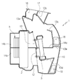
도 1은 종래의 2층류 차량용 공조장치를 도시한 단면도이다. 도 1을 참조하면, 종래의 2층류 차량용 공조장치(1)는 공조케이스(10)를 구비한다. 공조케이스(10)는 내부에 일정 형태의 공기 유로가 형성되고, 공기 유로는 분리벽(14c)에 의해 상부 유로(14b)와 하부 유로(14a)로 구획된다. 공조케이스(10)의 출구 측에는 다수의 공기토출구가 형성된다. 공기토출구는 디프로스트벤트(16), 페이스벤트(17), 전석 플로어벤트(18), 후석 플로어벤트(19)로 이루어진다.1 is a cross-sectional view showing a conventional two-layer air conditioner for a vehicle. Referring to FIG. 1, a conventional two-layer vehicle air conditioner 1 includes an
공조케이스(10)의 입구 측에는 블로어 유닛(5)이 구비되며, 공조케이스(10)의 공기 유로에 일정 간격을 두고 증발기(2)와 히터코어(3)가 구비된다. 상부 유로(14b)로는 외기가 유입되어 유동되며, 하부 유로(14a)로는 내기가 유입되어 유동된다. 상부 유로(14b)에는 히터코어(3)를 통과하는 공기와 히터코어(3)를 바이패스하는 공기의 양을 조절하는 제1 템프도어(11)가 구비되며, 하부 유로(14a)에는 히터코어(3)를 통과하는 공기와 히터코어(3)를 바이패스하는 공기의 양을 조절하는 제2 템프도어(12)가 구비된다.The inlet side of the
공기토출구에는 디프로스트벤트(16)와 페이스벤트(17)로 토출되는 공기량을 조절하는 디프로스트도어(13a)와 페이스도어(13b)가 각각 구비된다. 공기토출구는 전석 플로어벤트(18)로 토출되는 공기량을 조절하는 플로어도어(13c)와, 후석 플로어벤트(19)로 토출되는 공기량을 조절하는 후석 모드도어(13d)가 구비된다. 상부 유로(14b)와 하부 유로(14a)의 연통을 제어하는 바이패스도어(13e)가 구비되어, 하부 유로(14a)의 내기를 상부 유로(14b)로 유동시킬 수 있다.The air discharge port is provided with a defrost door (13a) and a face door (13b) for controlling the amount of air discharged to the defrost vent (16) and the face vent (17), respectively. The air discharge port is provided with a
한편, 차량용 공조장치는 엔진의 냉각수 열원을 이용하는 히터코어(Heater Core:3) 이외에도 전원의 인가에 의해 발열하여 이를 통과하는 공기를 가열하는 PTC히터(Positive Temperature Cofficient Heater)와 같은 전열히터를 더 구비할 수 있다. 전열히터는 PTC소자로 이루어진 발열부와, 발열부와 접촉하여 열을 방출하는 방열부와, 단자부 및 이들을 감싸 보호하는 하우징 등으로 이루어진다. 종래의 전열히터는 발열부 및 방열부의 배치를 최적화할 필요가 있다.Meanwhile, in addition to a heater core using a cooling water heat source of the engine, the vehicle air conditioner further includes an electric heater such as a PTC heater (Positive Temperature Cofficient Heater) that heats the air passing through it by applying power. can do. The electrothermal heater comprises a heating unit made of a PTC element, a heat dissipation unit that emits heat by contacting the heating unit, a terminal unit, and a housing surrounding and protecting them. In the conventional electric heater, it is necessary to optimize the arrangement of the heat generating portion and the heat dissipation portion.
이와 같은 종래의 문제점을 해결하기 위하여, 본 발명에서는 2층류 공조장치에 있어서 전열히터의 발열부 배치를 최적화하여 열해 손상을 방지하고 난방 성능을 개선할 수 있는 차량용 공조장치를 제공한다.In order to solve such a conventional problem, the present invention provides a vehicle air conditioning system capable of preventing heat damage and improving heating performance by optimizing the arrangement of the heating unit of the electric heater in the two-layer air conditioning system.
본 발명에 따른 차량용 공조장치는 내기와 외기를 분리 유입하며 공조케이스의 내부가 분리벽에 의해 상측 유로와 하측 유로로 구획된 차량용 공조장치에 있어서, 전원의 인가에 의해 발열하는 발열부와 공기와 열교환하는 방열부를 구비하는 전열히터를 포함하고, 상기 분리벽은 방열부와 마주하도록 전열히터가 배치된다.A vehicle air conditioner according to the present invention is a vehicle air conditioner that separates in and out air from inside and outside, and the inside of the air conditioner case is divided into an upper flow path and a lower flow path by a separation wall. It includes an electrothermal heater having a heat dissipation unit for heat exchange, the partition wall is arranged an electrothermal heater to face the heat dissipation unit.
상기에서, 전열히터의 발열부는 높이 방향으로 분리벽과 이격 배치된다.In the above, the heating portion of the electric heater is spaced apart from the separation wall in the height direction.
상기에서, 전열히터의 발열부는 짝수개로 구성된다.In the above, the heating portion of the electric heater is composed of an even number.
상기에서, 전열히터의 발열부는 높이 방향으로 분리벽을 기준으로 대칭되게 배치된다.In the above, the heating portion of the electric heater is symmetrically arranged with respect to the separation wall in the height direction.
상기에서, 전열히터의 발열부는 홀수개로 구성되며, 높이 방향으로 분리벽을 기준으로 비대칭되게 배치된다.In the above, the heating part of the electric heater is composed of an odd number, and is arranged asymmetrically with respect to the separation wall in the height direction.
상기에서, 전열히터의 발열부는 분리벽을 기준으로 상부보다 하부에 더 많은 개수가 구성된다.In the above, the heating unit of the electric heater is configured in a larger number than the upper portion based on the separation wall.
상기에서, 전열히터는 높이 방향으로 중간 부위가 분리벽에 위치하도록 설치된다.In the above, the heat transfer heater is installed such that the intermediate portion is positioned on the separation wall in the height direction.
상기에서, 공조케이스 내부에 냉각수 열원에 의해 공기를 가열하는 히터코어가 구비되고, 상기 전열히터는 공기 유동 방향으로 히터코어의 하류에 일체로 결합된다.In the above, a heater core for heating air by a cooling water heat source is provided inside the air conditioning case, and the electrothermal heater is integrally coupled downstream of the heater core in the air flow direction.
상기에서, 히터코어는: 일정거리 이격되어 나란하게 구비되는 제1 헤더탱크 및 제2 헤더탱크; 상기 제1 헤더탱크 또는 제2 헤더탱크에 구비되어 냉각수가 유입 및 배출되는 냉각수 파이프; 상기 제1 헤더탱크 및 제2 헤더탱크에 양단이 고정되어 냉각수 유로를 형성하는 복수개의 튜브; 상기 튜브 사이에 개재되는 핀; 상기 튜브 및 핀의 조립체 양측을 지지하는 한 쌍의 사이드 플레이트를 포함하고, 상기 전열히터는 발열부에 전원을 인가하기 위한 단자부를 구비하며, 상기 방열부는 판 형상으로 이루어져 발열부를 고정하고, 상기 방열부 및 발열부의 일측 단부가 하우징에 의해 지지된다.In the above, the heater core includes: a first header tank and a second header tank which are spaced apart at a predetermined distance and arranged side by side; A cooling water pipe provided in the first header tank or the second header tank, through which cooling water flows in and out; A plurality of tubes having both ends fixed to the first header tank and the second header tank to form a cooling water flow path; Fins interposed between the tubes; It includes a pair of side plates supporting both sides of the assembly of the tube and the fin, the electrothermal heater has a terminal portion for applying power to the heat generating portion, and the heat dissipating portion is formed in a plate shape to fix the heat generating portion, and the heat dissipation One end portion of the portion and the heating portion is supported by the housing.
상기에서, 공조케이스 내부에 냉각수 열원에 의해 공기를 가열하는 히터코어가 구비되고, 상기 전열히터는 공기 유동 방향으로 히터코어의 하류에 이격 배치되며, 히터코어와 전열히터의 사이에 배치된 분리벽은 상기 방열부의 대응하는 위치에 배치된다.In the above, a heater core for heating air by a cooling water heat source is provided inside the air conditioning case, and the heat transfer heater is spaced apart downstream of the heater core in the air flow direction, and a separation wall disposed between the heater core and the heat transfer heater Is disposed at the corresponding position of the heat dissipation unit.
본 발명에 따른 차량용 공조장치는 전열히터의 발열부 배치를 최적화하여 열해 손상을 방지함에 따라 열변형의 위험을 감소하고 안전성을 높이며, 발열부의 열교환 효율을 증가시켜 난방 성능을 개선할 뿐 아니라 풋 존으로의 토출 온도를 상승시켜 탑승자의 만족도를 높일 수 있다.The air conditioning system for a vehicle according to the present invention optimizes the heating element arrangement of the electric heater, thereby reducing the risk of thermal deformation and increasing safety as the heat is prevented from damage, and improving the heating performance by increasing the heat exchange efficiency of the heating element. By increasing the discharge temperature to the rider can increase the satisfaction of the passenger.
도 1은 종래의 2층류 차량용 공조장치를 도시한 단면도이고,
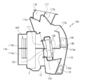
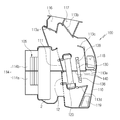
도 2는 본 발명의 일 실시 예에 따른 차량용 공조장치를 도시한 단면도이며,
도 3은 본 발명의 일 실시 예에 따른 히터코어와 전열히터의 분리 사시도이고,
도 4는 본 발명의 일 실시 예에 따른 히터코어와 전열히터의 조립체가 분리벽과 분리된 상태를 도시한 사시도이며,
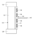
도 5는 본 발명의 일 실시 예에 따른 전열히터와 분리벽의 설치 상태를 도시한 단면도이고,
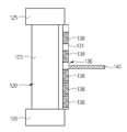
도 6 내지 도 8은 도 5의 변형 예에 따른 전열히터와 분리벽의 설치 상태를 도시한 단면도이며,
도 9는 본 발명의 다른 실시 예에 따른 차량용 공조장치를 도시한 단면도이고,
도 10은 본 발명의 다른 실시 예에 따른 전열히터와 분리벽의 설치 상태를 도시한 단면도이다.1 is a cross-sectional view showing a conventional two-layer air conditioning system for a vehicle,
Figure 2 is a cross-sectional view showing a vehicle air conditioning apparatus according to an embodiment of the present invention,
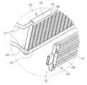
3 is an exploded perspective view of a heater core and an electric heater according to an embodiment of the present invention,
4 is a perspective view showing a state in which the assembly of the heater core and the electric heater according to an embodiment of the present invention is separated from the separation wall,
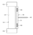
5 is a cross-sectional view showing the installation state of the electric heater and the separation wall according to an embodiment of the present invention,
6 to 8 is a cross-sectional view showing the installation state of the heating heater and the separation wall according to the modification of FIG. 5,
9 is a cross-sectional view showing a vehicle air conditioner according to another embodiment of the present invention,
10 is a cross-sectional view showing an installation state of an electric heater and a separation wall according to another embodiment of the present invention.
이하 첨부된 도면에 따라서 차량용 공조장치의 기술적 구성을 상세히 설명하면 다음과 같다.Hereinafter, the technical configuration of the vehicle air conditioner according to the accompanying drawings will be described in detail.
도 2는 본 발명의 일 실시 예에 따른 차량용 공조장치를 도시한 단면도이며, 도 3은 본 발명의 일 실시 예에 따른 히터코어와 전열히터의 분리 사시도이고, 도 4는 본 발명의 일 실시 예에 따른 히터코어와 전열히터의 조립체가 분리벽과 분리된 상태를 도시한 사시도이며, 도 5는 본 발명의 일 실시 예에 따른 전열히터와 분리벽의 설치 상태를 도시한 단면도이다.Figure 2 is a cross-sectional view showing a vehicle air conditioning apparatus according to an embodiment of the present invention, Figure 3 is an exploded perspective view of a heater core and an electric heater according to an embodiment of the present invention, Figure 4 is an embodiment of the present invention It is a perspective view showing a state in which the assembly of the heater core and the heating heater according to the separation wall, and Figure 5 is a cross-sectional view showing the installation state of the heating heater and the separation wall according to an embodiment of the present invention.
도 2 내지 도 5에 도시된 바와 같이, 본 발명의 일 실시 예에 따른 차량용 공조장치(100)는 난방시 디포깅을 위해 상부에는 외기를 공급하고 하부에는 내기를 순환시키는 2층류 공조장치로서 공조케이스(110)를 구비한다.2 to 5, the
공조케이스(110)는 내부에 일정 형태의 공기 유로(114)가 형성되고, 공기 유로(114)는 분리벽(140)에 의해 구획된 상측 유로(114b)와 하측 유로(114a)로 이루어진다. 하측 유로(114a)에는 내기가 유입되어 유동되고, 상측 유로(114b)에는 외기가 유입되어 유동된다. 즉, 공조케이스(110)는 내기와 외기를 분리 유입하며, 공조케이스(110)의 내부가 분리벽(140)에 의해 상측 유로(114b)와 하측 유로(114a)로 구획된다.The air-
하측 유로(114a)는 내기 유입구를 통해 유입된 내기가 유동하는 내기 유로로서, 분리벽(140)에 의해 구획된 상하 공간 중 하부에 위치한다. 상측 유로(114b)는 외기 유입구를 통해 유입된 외기가 유동하는 외기 유로로서, 분리벽(140)에 의해 구획된 상하 공간 중 상부에 위치한다.The
공조케이스(110)의 출구 측에는 다수의 공기토출구가 형성된다. 공기토출구는 디프로스트벤트(116), 페이스벤트(117), 전석 플로어벤트(118), 후석 플로어벤트(119)로 이루어진다.A plurality of air outlets are formed at the outlet side of the
공조케이스(110)의 입구 측에는 블로어 유닛(105)이 구비되며, 블로어 유닛(105)는 공조케이스(110)의 공기유입구에 연결된다. 공기유입구는 하측 유로(114a)와 상측 유로(114b)의 입구이다. 공조케이스(110)의 공기 유로에는 이를 통과하는 공기와 열교환하는 복수의 열교환기가 구비된다. 즉, 공조케이스(110)의 내부에는 공기유입구(114) 측에서부터 일정 간격을 두고 냉각용 열교환기인 증발기(102)와 가열용 열교환기인 히터코어(120)가 구비된다.The inlet side of the
공조케이스(110)의 공기 유로는 증발기(102)의 하류 측까지 분리벽(140)을 통해 상측 유로(114b)와 하측 유로(114a)로 구획된다. 상측 유로(114b)로 유입된 외기는 열교환기와 열교환한 후 디프로스트벤트(116), 페이스벤트(117) 및 전석 플로어벤트(118) 중 적어도 하나로 토출된다. 하측 유로(114a)로 유입된 내기는 열교환기와 열교환한 후 후석 플로어벤트(119)로 토출되거나 상측 유로(114b)로 유동하여 차량 전석 측으로 토출될 수 있다.The air flow path of the
상측 유로(114b)에는 히터코어(120)를 통과하는 공기와 히터코어(120)를 바이패스하는 공기의 양을 조절하는 제1 템프도어(111)가 구비되며, 하측 유로(114a)에는 히터코어(120)를 통과하는 공기와 히터코어(120)를 바이패스하는 공기의 양을 조절하는 제2 템프도어(112)가 구비된다.The
공조케이스(110)의 공기토출구에는 디프로스트벤트(116)와 페이스벤트(117)를 향하는 공기의 양을 조절하는 디프로스트도어(113a)와 페이스도어(113b)가 구비된다. 또한, 공기토출구에는 전석 플로어벤트(118)를 향하는 공기의 양을 조절하는 플로어도어(113c)와, 후석 플로어벤트(119)를 향하는 공기의 양을 조절하는 후석 모드도어(113d)가 구비된다. 아울러, 상측 유로(114b)와 하측 유로(114a) 간의 연통 유로 개도를 조절하는 바이패스도어(113e)가 구비되어, 하측 유로(114a)의 내기가 상측 유로(114b)로 유동할 수 있다.The air outlet of the
차량용 공조장치(100)는 전열히터(130)를 포함한다. 전열히터(130)는 공조케이스(110) 내부에 구비되며, 전원의 인가에 의해 발열하여 공기를 가열한다. 전열히터(130)는 PTC 히터(Positive Temperature Cofficient Heater)로 이루어질 수 있다. 전열히터(130)는 단자부(132)와, 발열부(138)와, 방열부(131) 및 하우징을 포함하여 이루어진다.The
단자부(132)는 전원을 공급받기 위한 것이며, 발열부(138)는 높이 방향으로 복수개가 이격 배열되며, 단자부(132)에 인가되는 전원에 의해 발열한다. 발열부(138)는 전극을 구비하며 PTC 소자를 이용하는 발열튜브로 이루어질 수 있다. 방열부(131)는 판 형상으로 이루어지며, 발열부(138)를 고정하고 발열부(138)에서 발생된 열을 이를 통과하는 공기와 열교환시킨다. 하우징은 방열부(131) 및 발열부(138)의 일측 단부를 지지한다.The
히터코어(120)는 공조케이스(110) 내부에 구비되며, 냉각수 열원에 의해 공기를 가열한다. 히터코어(120)는 제1 헤더탱크(125) 및 제2 헤더탱크(126)와, 냉각수 파이프(121)와, 튜브(123)와, 핀(128) 및 사이드 플레이트(122)를 포함하여 이루어진다.The
제1 헤더탱크(125) 및 제2 헤더탱크(126)는 높이 방향으로 일정거리 이격되어 나란하게 구비된다. 제1 헤더탱크(125)와 제2 헤더탱크(126) 중 하나에는 냉각수를 유입하기 위한 냉각수 파이프(121)가 구비되며, 다른 하나에는 냉각수를 배출하기 위한 냉각수 파이프(121)가 구비된다.The
튜브(123)는 제1 헤더탱크(125) 및 제2 헤더탱크(126)에 양단이 고정되어 냉각수 유로를 형성하는 것으로서, 폭 방향으로 복수개가 나란하게 구비된다. 핀(128)은 복수개의 튜브(123) 사이에 개재되어, 이를 통과하는 공기와 열교환함으로써 열교환 성능을 향상시킨다. 사이드 플레이트(122)는 한 쌍으로 이루어지고 튜브(123) 및 핀(128)의 조립체 양측을 지지한다.The
전열히터(130)는 공기 유동 방향으로 히터코어(120)의 하류에 일체로 결합된다. 즉, 전열히터의 방열부(131) 양단이 히터코어(120)의 제1,2 헤더탱크(125,126)에 슬라이딩 삽입 체결되어 히터코어(120) 및 전열히터(130)는 서로 마주하며 접촉되는 콤보(Combo) PTC 형태의 열교환기 조립체를 구성할 수 있다.The
따라서, 히터코어(120)를 통과한 공기 전체가 전열히터(130)를 통과하여 열교환함에 따라 열효율이 증대되며 하나의 열교환기 조립체를 공조케이스에 결합하면 되어 조립 공정수를 줄일 수 있다. 본 실시 예에서는 콤보 PTC 형태의 가열용 열교환기를 적용하였으나, 히터코어와 전열히터가 분리된 구조 또는 전열히터만 구비된 구조로도 구현이 가능하다.Therefore, as the entire air passing through the
전열히터(130)는 높이 방향으로 중간 부위가 분리벽(140)에 위치하도록 설치된다. 즉, 전열히터(130)는 상측 유로(14b)와 하측 유로(14a)에 걸쳐서 설치되고 분리벽(140)이 전열히터(130)의 높이 방향 중간 부위에 위치한다. 따라서, 각 유로에서 전열히터(130)를 균등하게 열원으로 사용할 수 있다.The
상기 분리벽(140)은 방열부(131)와 마주하도록 전열히터(130)가 배치된다. 즉, 전열히터(130)의 발열부(138)는 높이 방향으로 분리벽(140)과 이격 배치된다. 이와 같이, 공조케이스(110)의 분리벽(140)이 전열히터(130)의 방열부(131)와 마주하며 발열부(138)와 이격되는 구성을 통해, 고온의 발열부(138)에 의한 분리벽(140)의 열해를 방지하고 발열부(138)의 열교환 효율을 증대시켜 난방 성능의 향상을 기대할 수 있다.The
발열부(138)를 분리벽(140)과 높이 방향으로 이격시키기 위한 첫번째 구조로, 전열히터(130)의 발열부(138)가 짝수개로 구성된다. 이 경우, 전열히터(130)의 발열부(138)는 높이 방향으로 분리벽(140)을 기준으로 대칭되게 배치된다.As a first structure for separating the
상하 온도 배치를 균일하게 하기 위해, 발열부(138)를 홀수개로 구성할 경우 그리고 발열부(138)를 높이 방향으로 대칭되게 구성할 경우, 이 두 가지 경우를 모두 만족하기 위해서는 불가피하게 분리벽(140)이 전열히터(130)의 높이 방향 중간 부위에 위치하여야 한다. 이로 인해, 높이 방향 중간 부위에 위치한 발열부(138)가 분리벽(140)과 접촉하는 문제가 발생한다.In order to uniformly arrange the upper and lower temperature, when the
따라서, 본 실시 예와 같이 발열부(138)를 짝수개로 구성하게 되면, 어떠한 발열부(138)도 직접 분리벽(140)과 접촉하지 않게 되고 발열부(138)를 높이 방향으로 대칭되게 구성할 수 있어 상하 온도 배치를 균일하게 할 수 있다.Therefore, if the
한편, 도 6 내지 도 8은 도 5의 변형 예에 따른 전열히터와 분리벽의 설치 상태를 도시한 단면도이다.Meanwhile, FIGS. 6 to 8 are cross-sectional views showing an installation state of the heat transfer heater and the separation wall according to the modified example of FIG. 5.
도 6을 참조하면, 발열부(138)를 분리벽(140)과 높이 방향으로 이격시키기 위한 두번째 구조로, 전열히터(130)의 발열부(138)는 홀수개로 구성되며, 높이 방향으로 분리벽(140)을 기준으로 비대칭되게 배치된다. 이 경우, 전열히터(130)의 발열부(138)는 분리벽(140)을 기준으로 상부보다 하부에 더 많은 개수가 구성되는 것이 바람직하다.Referring to FIG. 6, a second structure for separating the
하측 유로(14a)는 내기가 유입되어 순환되는 유로로서, 난방 모드 시 히터코어(120) 및 전열히터(130)에 의해 가열된 공기가 유동하는 주요 사용부이다. 따라서, 탑승자 발(Foot) 측으로의 토출 온도 상승을 위해, 전열히터(130)의 발열부(138)를 풋 존(Foot Zone) 근접 부위에 더 많이 편심 배치시켜, 분리벽(140)의 온도 상승 방지와 난방 성능 개선 효과를 동시에 달성할 수 있다.The
또한, 도 7과 같이, 발열부(138)를 짝수개로 구성할 경우, 분리벽(140)을 기준으로 상측 유로에 2개, 하측 유로에 2개로 구성하거나 또는 그 이상으로 구성할 수 있다. 아울러, 도 8과 같이 발열부(138)를 홀수개로 구성할 경우, 분리벽(140)을 기준으로 상측 유로에 2개, 하측 유로에 3개로 구성하거나 또는 그 이상으로 구성할 수 있다.In addition, as shown in FIG. 7, when the
한편, 도 9는 본 발명의 다른 실시 예에 따른 차량용 공조장치를 도시한 단면도이고, 도 10은 본 발명의 다른 실시 예에 따른 전열히터와 분리벽의 설치 상태를 도시한 단면도이다.Meanwhile, FIG. 9 is a cross-sectional view showing an air conditioning apparatus for a vehicle according to another embodiment of the present invention, and FIG. 10 is a cross-sectional view showing an installation state of an electric heater and a separation wall according to another embodiment of the present invention.
도 9 및 도 10을 참조하면, 본 발명의 다른 실시 예에 따른 차량용 공조장치는 전열히터(130)가 공기 유동 방향으로 히터코어(120)의 하류에 이격 배치된다. 이 경우, 히터코어(120)와 전열히터(130)의 사이에 배치된 분리벽(140)은 방열부(131)의 대응하는 위치에 배치된다. 이와 같이, 히터코어와 전열히터가 일체로 결합된 구조 이외에도 히터코어와 전열히터가 이격된 구조의 경우, 방열부(131)가 분리벽(140)에 대응되는 위치에 배치됨에 따라 분리벽(140)과 발열부(138)의 직접적인 접촉이 방지되어 열해 손상 문제를 해결한다.9 and 10, in the vehicle air conditioning apparatus according to another embodiment of the present invention, the
지금까지 본 발명에 따른 차량용 공조장치는 도면에 도시된 실시 예를 참고로 설명되었으나 이는 예시적인 것에 불과하며, 당업자라면 누구든지 이로부터 다양한 변형 및 균등한 다른 실시 예가 가능하다는 점을 이해할 것이다. 따라서, 진정한 기술적 보호 범위는 첨부된 특허청구범위의 기술적 사상에 의하여 정해져야 할 것이다.So far, the vehicle air conditioning apparatus according to the present invention has been described with reference to the embodiment shown in the drawings, but this is only exemplary, and anyone skilled in the art will understand that various modifications and equivalent other embodiments are possible therefrom. Therefore, the true technical protection scope should be determined by the technical spirit of the appended claims.
100: 차량용 공조장치
102: 증발기
110: 공조케이스
111: 제1 템프도어
112: 제2 템프도어
114a: 하측 유로
114b: 상측 유로
120: 히터코어
130: 전열히터
131: 방열부
138: 발열부
140: 분리벽100: vehicle air conditioning system
102: evaporator 110: air conditioning case
111: first temp door 112: second temp door
114a:
120: heater core 130: electric heater
131: heat dissipation section 138: heating section
140: partition wall
Claims (10)
전원의 인가에 의해 발열하는 발열부(138)와 공기와 열교환하는 방열부(131)를 구비하는 전열히터(130)를 포함하고,
상기 분리벽(140)은 방열부(131)와 마주하도록 전열히터(130)가 배치되는 차량용 공조장치.In the air conditioning device for the vehicle divided into the inside and outside air and the inside of the air conditioning case 110 is divided into the upper flow path 114b and the lower flow path 114a by the separation wall 140,
It includes an electric heater 130 having a heat generating portion 138 to generate heat by the application of power and a heat dissipation portion 131 to exchange heat with air,
The dividing wall 140 is a vehicle air conditioning device in which the heat transfer heater 130 is disposed to face the heat dissipation unit 131.
상기 전열히터(130)의 발열부(138)는 높이 방향으로 분리벽(140)과 이격 배치되는 차량용 공조장치.According to claim 1,
The heating unit 138 of the heating heater 130 is a vehicle air conditioner that is spaced apart from the separation wall 140 in the height direction.
상기 전열히터(130)의 발열부(138)는 짝수개로 구성되는 것을 특징으로 하는 차량용 공조장치.According to claim 1,
The heating unit 138 of the electric heater 130 is a vehicle air conditioning apparatus, characterized in that consisting of an even number.
상기 전열히터(130)의 발열부(138)는 높이 방향으로 분리벽(140)을 기준으로 대칭되게 배치되는 것을 특징으로 하는 차량용 공조장치.According to claim 3,
The heating unit 138 of the heating heater 130 is a vehicle air conditioning apparatus, characterized in that arranged symmetrically with respect to the separation wall 140 in the height direction.
상기 전열히터(130)의 발열부(138)는 홀수개로 구성되며, 높이 방향으로 분리벽(140)을 기준으로 비대칭되게 배치되는 것을 특징으로 하는 차량용 공조장치.According to claim 1,
The heating unit 138 of the heating heater 130 is composed of an odd number, the vehicle air conditioning apparatus, characterized in that arranged asymmetrically relative to the separation wall 140 in the height direction.
상기 전열히터(130)의 발열부(138)는 분리벽(140)을 기준으로 상부보다 하부에 더 많은 개수가 구성되는 차량용 공조장치.The method of claim 5,
The heating unit 138 of the heating heater 130 is a vehicle air conditioning device that is configured in a larger number than the upper portion based on the separation wall 140.
상기 전열히터(130)는 높이 방향으로 중간 부위가 분리벽(140)에 위치하도록 설치되는 차량용 공조장치.According to claim 1,
The heating heater 130 is a vehicle air conditioner that is installed so that the intermediate portion in the height direction is located on the separation wall (140).
상기 공조케이스(110) 내부에 냉각수 열원에 의해 공기를 가열하는 히터코어(120)가 구비되고,
상기 전열히터(130)는 공기 유동 방향으로 히터코어(120)의 하류에 일체로 결합되는 차량용 공조장치.According to claim 1,
A heater core 120 for heating air by a cooling water heat source is provided in the air conditioning case 110,
The electric heater 130 is a vehicle air conditioning unit that is integrally coupled to the downstream of the heater core 120 in the air flow direction.
상기 히터코어(120)는: 일정거리 이격되어 나란하게 구비되는 제1 헤더탱크(125) 및 제2 헤더탱크(126); 상기 제1 헤더탱크(125) 또는 제2 헤더탱크(126)에 구비되어 냉각수가 유입 및 배출되는 냉각수 파이프(121); 상기 제1 헤더탱크(125) 및 제2 헤더탱크(126)에 양단이 고정되어 냉각수 유로를 형성하는 복수개의 튜브(123); 상기 튜브(123) 사이에 개재되는 핀(128); 상기 튜브(123) 및 핀(128)의 조립체 양측을 지지하는 한 쌍의 사이드 플레이트(122)를 포함하고,
상기 전열히터(130)는 발열부(138)에 전원을 인가하기 위한 단자부(132)를 구비하며, 상기 방열부(131)는 판 형상으로 이루어져 발열부(138)를 고정하고, 상기 방열부(131) 및 발열부(138)의 일측 단부가 하우징에 의해 지지되는 차량용 공조장치.The method of claim 8,
The heater core 120 includes: a first header tank 125 and a second header tank 126 provided side by side at a predetermined distance; A cooling water pipe 121 provided in the first header tank 125 or the second header tank 126 to flow in and out cooling water; A plurality of tubes 123 fixed to both ends of the first header tank 125 and the second header tank 126 to form a cooling water flow path; A fin 128 interposed between the tubes 123; It includes a pair of side plates 122 supporting both sides of the assembly of the tube 123 and the pin 128,
The heating heater 130 includes a terminal portion 132 for applying power to the heating portion 138, and the heat dissipation portion 131 is formed in a plate shape to fix the heat generating portion 138, and the heat dissipation portion ( 131) and one end of the heating unit 138, the vehicle air conditioning apparatus supported by the housing.
상기 공조케이스(110) 내부에 냉각수 열원에 의해 공기를 가열하는 히터코어(120)가 구비되고, 상기 전열히터(130)는 공기 유동 방향으로 히터코어(120)의 하류에 이격 배치되며,
히터코어(120)와 전열히터(130)의 사이에 배치된 분리벽(140)은 상기 방열부(131)의 대응하는 위치에 배치되는 차량용 공조장치.According to claim 1,
Inside the air conditioning case 110, a heater core 120 for heating air by a cooling water heat source is provided, and the heat transfer heater 130 is spaced apart downstream of the heater core 120 in the air flow direction,
The air conditioning device for a vehicle is disposed at a corresponding position of the heat dissipation unit 131, the separation wall 140 disposed between the heater core 120 and the electric heater 130.
Priority Applications (5)
| Application Number | Priority Date | Filing Date | Title |
|---|---|---|---|
| KR1020180119958A KR102592456B1 (en) | 2018-10-08 | 2018-10-08 | Air conditioner for vehicle |
| CN201910931029.4A CN111002787B (en) | 2018-10-08 | 2019-09-29 | Member with through hole and vehicle air conditioner provided with same |
| DE102019126822.2A DE102019126822B4 (en) | 2018-10-08 | 2019-10-07 | Air conditioning for a vehicle |
| JP2019184233A JP6918066B2 (en) | 2018-10-08 | 2019-10-07 | Penetration member and air conditioner for vehicles equipped with it |
| US16/595,566 US11912102B2 (en) | 2018-10-08 | 2019-10-08 | Perforated member and air conditioner for vehicle having same |
Applications Claiming Priority (1)
| Application Number | Priority Date | Filing Date | Title |
|---|---|---|---|
| KR1020180119958A KR102592456B1 (en) | 2018-10-08 | 2018-10-08 | Air conditioner for vehicle |
Publications (2)
| Publication Number | Publication Date |
|---|---|
| KR20200040102A true KR20200040102A (en) | 2020-04-17 |
| KR102592456B1 KR102592456B1 (en) | 2023-10-23 |
Family
ID=70460740
Family Applications (1)
| Application Number | Title | Priority Date | Filing Date |
|---|---|---|---|
| KR1020180119958A Active KR102592456B1 (en) | 2018-10-08 | 2018-10-08 | Air conditioner for vehicle |
Country Status (1)
| Country | Link |
|---|---|
| KR (1) | KR102592456B1 (en) |
Cited By (1)
| Publication number | Priority date | Publication date | Assignee | Title |
|---|---|---|---|---|
| KR20230146852A (en) * | 2022-04-13 | 2023-10-20 | 한온시스템 주식회사 | Heat apparatus for vehicle |
Citations (4)
| Publication number | Priority date | Publication date | Assignee | Title |
|---|---|---|---|---|
| JPS6143984A (en) * | 1984-08-03 | 1986-03-03 | Unitika Ltd | Formed article for tissue culture |
| JPH10324145A (en) * | 1997-05-23 | 1998-12-08 | Denso Corp | Vehicle air conditioner |
| KR101179593B1 (en) | 2005-11-10 | 2012-09-05 | 한라공조주식회사 | Airconditioner having structure of two layer air flow for vehicles |
| JP2015519260A (en) * | 2012-07-09 | 2015-07-09 | ハラ ビステオン クライメイト コントロール コーポレイション | Vehicle heater |
-
2018
- 2018-10-08 KR KR1020180119958A patent/KR102592456B1/en active Active
Patent Citations (4)
| Publication number | Priority date | Publication date | Assignee | Title |
|---|---|---|---|---|
| JPS6143984A (en) * | 1984-08-03 | 1986-03-03 | Unitika Ltd | Formed article for tissue culture |
| JPH10324145A (en) * | 1997-05-23 | 1998-12-08 | Denso Corp | Vehicle air conditioner |
| KR101179593B1 (en) | 2005-11-10 | 2012-09-05 | 한라공조주식회사 | Airconditioner having structure of two layer air flow for vehicles |
| JP2015519260A (en) * | 2012-07-09 | 2015-07-09 | ハラ ビステオン クライメイト コントロール コーポレイション | Vehicle heater |
Cited By (1)
| Publication number | Priority date | Publication date | Assignee | Title |
|---|---|---|---|---|
| KR20230146852A (en) * | 2022-04-13 | 2023-10-20 | 한온시스템 주식회사 | Heat apparatus for vehicle |
Also Published As
| Publication number | Publication date |
|---|---|
| KR102592456B1 (en) | 2023-10-23 |
Similar Documents
| Publication | Publication Date | Title |
|---|---|---|
| JP6918066B2 (en) | Penetration member and air conditioner for vehicles equipped with it | |
| US20100300644A1 (en) | Temperature control system for seat of vehicles | |
| US20080061159A1 (en) | Electrical heater and vehicle air conditioner | |
| JP2017030742A (en) | Integrated module of vaporizer core for air conditioner and heater core | |
| KR101403441B1 (en) | A cooling and heating device of rear seat for vehicles using thermoelectric element | |
| KR102694367B1 (en) | Member with perforated hole and air conditioner for vehicle | |
| KR102592456B1 (en) | Air conditioner for vehicle | |
| JPH07149135A (en) | Air conditioner for vehicle | |
| KR20170105148A (en) | Electric heater | |
| JP2018203063A (en) | Vehicular air-conditioning device | |
| KR101715727B1 (en) | Air conditioner for vehicle with thermoelement module | |
| KR20110062803A (en) | Car air conditioner | |
| KR102844200B1 (en) | Air conditioner for vehicle | |
| KR102095394B1 (en) | Dual zone type air conditioner for vehicle | |
| KR101746232B1 (en) | Air conditioner for vehicle | |
| KR102898854B1 (en) | Heating device for vehicle and air conditioner for vehicle having the same | |
| KR20150010441A (en) | Thermoelectric Module of Heating and Cooling System used seat of automobile | |
| KR101173312B1 (en) | Cover Structure of Heater Core Pipe for an Air Conditioning System of a Car | |
| JP7585245B2 (en) | Vehicle air conditioning system | |
| KR102707217B1 (en) | Air conditioner for vehicle | |
| KR102932299B1 (en) | Air conditioner for vehicle | |
| US20240227642A9 (en) | Headrest air-conditioning device for vehicles | |
| KR20180086630A (en) | Air conditioner for vehicle | |
| KR20230096371A (en) | Heating device for vehicle and air conditioner for vehicle having the same | |
| KR101151524B1 (en) | Heater Core Fixing Structure of Air Conditioning System for a Car |
Legal Events
| Date | Code | Title | Description |
|---|---|---|---|
| PA0109 | Patent application |
St.27 status event code: A-0-1-A10-A12-nap-PA0109 |
|
| PG1501 | Laying open of application |
St.27 status event code: A-1-1-Q10-Q12-nap-PG1501 |
|
| E14-X000 | Pre-grant third party observation filed |
St.27 status event code: A-2-3-E10-E14-opp-X000 |
|
| PA0201 | Request for examination |
St.27 status event code: A-1-2-D10-D11-exm-PA0201 |
|
| D13-X000 | Search requested |
St.27 status event code: A-1-2-D10-D13-srh-X000 |
|
| D14-X000 | Search report completed |
St.27 status event code: A-1-2-D10-D14-srh-X000 |
|
| E902 | Notification of reason for refusal | ||
| PE0902 | Notice of grounds for rejection |
St.27 status event code: A-1-2-D10-D21-exm-PE0902 |
|
| AMND | Amendment | ||
| E13-X000 | Pre-grant limitation requested |
St.27 status event code: A-2-3-E10-E13-lim-X000 |
|
| P11-X000 | Amendment of application requested |
St.27 status event code: A-2-2-P10-P11-nap-X000 |
|
| P13-X000 | Application amended |
St.27 status event code: A-2-2-P10-P13-nap-X000 |
|
| E601 | Decision to refuse application | ||
| PE0601 | Decision on rejection of patent |
St.27 status event code: N-2-6-B10-B15-exm-PE0601 |
|
| X091 | Application refused [patent] | ||
| AMND | Amendment | ||
| E13-X000 | Pre-grant limitation requested |
St.27 status event code: A-2-3-E10-E13-lim-X000 |
|
| P11-X000 | Amendment of application requested |
St.27 status event code: A-2-2-P10-P11-nap-X000 |
|
| P13-X000 | Application amended |
St.27 status event code: A-2-2-P10-P13-nap-X000 |
|
| PX0901 | Re-examination |
St.27 status event code: A-2-3-E10-E12-rex-PX0901 |
|
| PX0701 | Decision of registration after re-examination |
St.27 status event code: A-3-4-F10-F13-rex-PX0701 |
|
| X701 | Decision to grant (after re-examination) | ||
| GRNT | Written decision to grant | ||
| PR0701 | Registration of establishment |
St.27 status event code: A-2-4-F10-F11-exm-PR0701 |
|
| PR1002 | Payment of registration fee |
St.27 status event code: A-2-2-U10-U11-oth-PR1002 Fee payment year number: 1 |
|
| PG1601 | Publication of registration |
St.27 status event code: A-4-4-Q10-Q13-nap-PG1601 |
|
| PN2301 | Change of applicant |
St.27 status event code: A-5-5-R10-R13-asn-PN2301 St.27 status event code: A-5-5-R10-R11-asn-PN2301 |
|
| R11 | Change to the name of applicant or owner or transfer of ownership requested |
Free format text: ST27 STATUS EVENT CODE: A-5-5-R10-R11-ASN-PN2301 (AS PROVIDED BY THE NATIONAL OFFICE) |
|
| R13 | Change to the name of applicant or owner recorded |
Free format text: ST27 STATUS EVENT CODE: A-5-5-R10-R13-ASN-PN2301 (AS PROVIDED BY THE NATIONAL OFFICE) |