KR20200040480A - Apparatus and method for discharging gas - Google Patents
Apparatus and method for discharging gas Download PDFInfo
- Publication number
- KR20200040480A KR20200040480A KR1020180120445A KR20180120445A KR20200040480A KR 20200040480 A KR20200040480 A KR 20200040480A KR 1020180120445 A KR1020180120445 A KR 1020180120445A KR 20180120445 A KR20180120445 A KR 20180120445A KR 20200040480 A KR20200040480 A KR 20200040480A
- Authority
- KR
- South Korea
- Prior art keywords
- gas
- space
- guide member
- gas discharge
- discharge device
- Prior art date
- Legal status (The legal status is an assumption and is not a legal conclusion. Google has not performed a legal analysis and makes no representation as to the accuracy of the status listed.)
- Granted
Links
Images

Classifications
-
- B—PERFORMING OPERATIONS; TRANSPORTING
- B23—MACHINE TOOLS; METAL-WORKING NOT OTHERWISE PROVIDED FOR
- B23K—SOLDERING OR UNSOLDERING; WELDING; CLADDING OR PLATING BY SOLDERING OR WELDING; CUTTING BY APPLYING HEAT LOCALLY, e.g. FLAME CUTTING; WORKING BY LASER BEAM
- B23K31/00—Processes relevant to this subclass, specially adapted for particular articles or purposes, but not covered by any single one of main groups B23K1/00 - B23K28/00
- B23K31/02—Processes relevant to this subclass, specially adapted for particular articles or purposes, but not covered by any single one of main groups B23K1/00 - B23K28/00 relating to soldering or welding
-
- F—MECHANICAL ENGINEERING; LIGHTING; HEATING; WEAPONS; BLASTING
- F17—STORING OR DISTRIBUTING GASES OR LIQUIDS
- F17C—VESSELS FOR CONTAINING OR STORING COMPRESSED, LIQUEFIED OR SOLIDIFIED GASES; FIXED-CAPACITY GAS-HOLDERS; FILLING VESSELS WITH, OR DISCHARGING FROM VESSELS, COMPRESSED, LIQUEFIED, OR SOLIDIFIED GASES
- F17C3/00—Vessels not under pressure
-
- B—PERFORMING OPERATIONS; TRANSPORTING
- B23—MACHINE TOOLS; METAL-WORKING NOT OTHERWISE PROVIDED FOR
- B23K—SOLDERING OR UNSOLDERING; WELDING; CLADDING OR PLATING BY SOLDERING OR WELDING; CUTTING BY APPLYING HEAT LOCALLY, e.g. FLAME CUTTING; WORKING BY LASER BEAM
- B23K2101/00—Articles made by soldering, welding or cutting
- B23K2101/04—Tubular or hollow articles
- B23K2101/12—Vessels
-
- F—MECHANICAL ENGINEERING; LIGHTING; HEATING; WEAPONS; BLASTING
- F17—STORING OR DISTRIBUTING GASES OR LIQUIDS
- F17C—VESSELS FOR CONTAINING OR STORING COMPRESSED, LIQUEFIED OR SOLIDIFIED GASES; FIXED-CAPACITY GAS-HOLDERS; FILLING VESSELS WITH, OR DISCHARGING FROM VESSELS, COMPRESSED, LIQUEFIED, OR SOLIDIFIED GASES
- F17C2209/00—Vessel construction, in particular methods of manufacturing
- F17C2209/22—Assembling processes
- F17C2209/221—Welding
Landscapes
- Engineering & Computer Science (AREA)
- Mechanical Engineering (AREA)
- General Engineering & Computer Science (AREA)
- Filling Or Discharging Of Gas Storage Vessels (AREA)
Abstract
본 발명은 예컨대 거대한 탱크와 같은 구조물 내에서 작업 중에 발생하는 용접가스 등의 가스를 효과적으로 배출하기 위한 가스 배출 장치 및 방법에 관한 것으로, 가스 배출 장치는, 밀폐된 공간을 형성하는 구조물의 측벽에서 이격되게 배치되어 상기 구조물 내에 유도 공간을 구획하는 가이드 부재; 상기 구조물 내에 설치되어 상기 구조물 내에 있는 가스를 상기 유도 공간 쪽으로 유동시키는 가스 유동 수단; 및 상기 구조물에 설치되어 상기 유도 공간으로 유동된 가스를 상기 구조물의 외부로 배출하도록 흡입하는 가스 흡입 수단을 포함한다. The present invention relates to a gas discharge device and a method for effectively discharging gas such as welding gas generated during work in a structure such as a large tank, the gas discharge device being spaced apart from a side wall of a structure forming a closed space A guide member which is arranged so as to partition the guide space in the structure; Gas flow means installed in the structure to flow gas in the structure toward the induction space; And gas suction means installed in the structure to suck gas flowing into the induction space to be discharged to the outside of the structure.
Description
본 발명은 예컨대 거대한 탱크와 같은 구조물 내에서 작업 중에 발생하는 용접가스 등의 가스를 효과적으로 배출할 수 있는 가스 배출 장치 및 방법에 관한 것이다. The present invention relates to a gas discharge device and method capable of effectively discharging gas such as welding gas generated during work in a structure such as a large tank.
LNG는 산업 전반에 사용되는 고효율 천연가스로서, 통상 바다에서 LNG용 선박으로부터 액상의 LNG를 공급받아 육상의 거대한 탱크에 저장하게 된다. LNG is a high-efficiency natural gas used in the entire industry, and is normally supplied with liquid LNG from LNG ships in the sea and stored in a huge tank on land.
이러한 탱크는 안전을 위해 이중 격벽으로 제조된다. 우선, 외부는 콘크리트 구조물로 된 외부용기로 보호되고, 이 구조물의 내부에 예컨대 강판과 같은 금속재 구조물로 된 내부용기가 설치된다. These tanks are made of double bulkheads for safety. First, the outside is protected by an external container made of a concrete structure, and an internal container made of a metal structure such as a steel plate is installed inside the structure.
외부용기 내에서 내부용기를 제조할 때, 강판의 용접에 의한 용접가스가 다량 발생하게 되고, 이로 인하여 내부의 작업환경이 악화된다. 특히, 예를 들어 Mn의 함유량이 많은 강판을 용접하게 되면, Mn의 농도가 높아져 작업자의 안전을 위협한다. When manufacturing the inner container in the outer container, a large amount of welding gas is generated by welding of the steel sheet, thereby deteriorating the internal working environment. In particular, when welding a steel sheet having a high Mn content, for example, the concentration of Mn increases, which threatens the safety of workers.
이에 따라, 내부용기의 제조를 위한 용접작업시 필수적으로 내부의 환기가 필요하다. Accordingly, it is necessary to internally ventilate during welding work for manufacturing the inner container.
(특허문헌 1) JP 2006-218490 A (Patent Document 1) JP 2006-218490 A
이에 본 발명은 예컨대 거대한 탱크와 같은 구조물 내에서 작업 중에 발생하는 용접가스 등의 가스를 효과적으로 배출하기 위한 가스 배출 장치 및 방법을 제공하는 데에 그 목적이 있다. Accordingly, an object of the present invention is to provide a gas discharge device and method for effectively discharging gas such as welding gas generated during work in a structure such as a large tank.
본 발명에 따른 가스 배출 장치는, 밀폐된 공간을 형성하는 구조물의 측벽에서 이격되게 배치되어 상기 구조물 내에 유도 공간을 구획하는 가이드 부재; 상기 구조물 내에 설치되어 상기 구조물 내에 있는 가스를 상기 유도 공간 쪽으로 유동시키는 가스 유동 수단; 및 상기 구조물에 설치되어 상기 유도 공간으로 유동된 가스를 상기 구조물의 외부로 배출하도록 흡입하는 가스 흡입 수단을 포함하는 것을 특징으로 한다. The gas discharge device according to the present invention includes a guide member that is spaced apart from a side wall of a structure forming an enclosed space and partitions an induction space in the structure; Gas flow means installed in the structure to flow gas in the structure toward the induction space; And it is characterized in that it comprises a gas suction means installed in the structure to suck the gas flowing into the induction space to discharge to the outside of the structure.
또한, 본 발명에 따른 가스 배출 방법은, 밀폐된 공간 내에 유도 공간이 구획된 구조물을 준비하는 단계; 상기 구조물 내에 있는 가스를 상기 유도 공간 쪽으로 유동시키는 단계; 및 상기 유도 공간으로 유동된 가스를 상기 구조물의 외부로 배출하도록 흡입하는 단계를 포함하는 것을 특징으로 한다. In addition, the gas discharge method according to the present invention comprises the steps of: preparing a structure in which an induction space is partitioned in a closed space; Flowing gas in the structure toward the induction space; And inhaling the gas flowing into the induction space so as to discharge it to the outside of the structure.
이상과 같이 본 발명에 의하면, 예컨대 거대한 탱크와 같은 구조물 내에서 작업 중에 발생하는 용접가스 등의 가스를 효과적으로 배출하게 됨으로써, 작업 효율을 향상시키고 작업자의 안전을 도모할 수 있는 효과를 얻게 된다. According to the present invention as described above, for example, by effectively discharging gas such as welding gas generated during work in a structure such as a large tank, it is possible to improve the working efficiency and obtain the effect of promoting worker safety.
도 1은 본 발명에 따른 가스 배출 장치를 개략적으로 도시한 도면이다. 1 is a view schematically showing a gas discharge device according to the present invention.
이하, 본 발명이 예시적인 도면을 통해 상세하게 설명된다. 각 도면의 구성요소들에 참조부호를 부가함에 있어서, 동일한 구성요소들에 대해서는 비록 다른 도면상에 표시되더라도 가능한 한 동일한 부호를 가지도록 하고 있음에 유의해야 한다. 또한, 본 발명을 설명함에 있어, 관련된 공지 구성 또는 기능에 대한 구체적인 설명이 본 발명의 요지를 흐릴 수 있다고 판단되는 경우에는 그 상세한 설명은 생략한다.Hereinafter, the present invention will be described in detail through exemplary drawings. It should be noted that in adding reference numerals to the components of each drawing, the same components have the same reference numerals as possible even though they are displayed on different drawings. In addition, in describing the present invention, when it is determined that detailed descriptions of related well-known structures or functions may obscure the subject matter of the present invention, detailed descriptions thereof will be omitted.
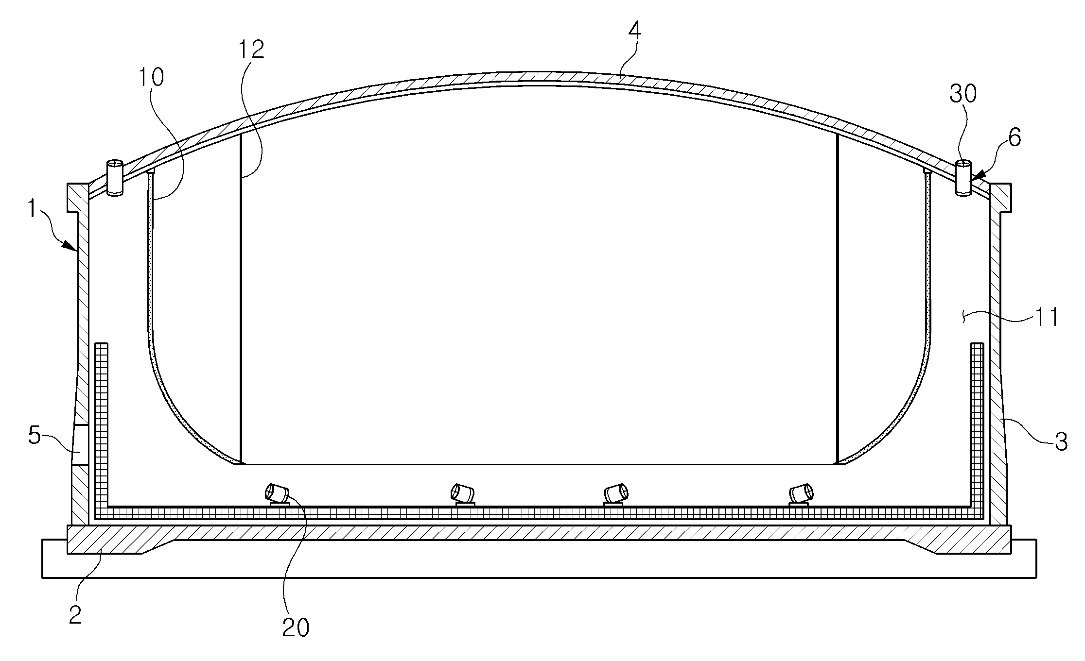
도 1은 본 발명에 따른 가스 배출 장치를 개략적으로 도시한 도면으로서, 이에 도시된 바와 같이, 본 발명에 따른 가스 배출 장치는, 밀폐된 공간을 형성하는 구조물(1)의 측벽(3)에서 이격되게 배치되어 구조물 내에 유도 공간(11)을 구획하는 가이드 부재(10); 구조물 내에 설치되어 구조물 내에 있는 가스를 유도 공간 쪽으로 유동시키는 가스 유동 수단(20); 및 구조물에 설치되어 유도 공간으로 유동된 가스를 구조물의 외부로 배출하도록 흡입하는 가스 흡입 수단(30)을 포함하고 있다. 1 is a view schematically showing a gas discharge device according to the present invention, as shown therein, the gas discharge device according to the present invention, spaced apart from the
구조물(1)은 예컨대 거대한 탱크와 같이 밀폐된 공간을 형성할 수 있다. 이러한 구조물 내에서 내부용기와 같은 또 다른 구조물을 제조할 때 본 발명의 가스 배출 장치가 유용하다. The structure 1 can form an enclosed space, for example a huge tank. The gas discharge device of the present invention is useful when manufacturing another structure such as an inner container in such a structure.
예를 들어, 구조물(1)은 콘크리트 구조물로 형성될 수 있으며, 원형, 타원형, 또는 다각형 등과 같은 소정의 단면 형상을 가진 바닥(2)과, 이 바닥으로부터 직립하여 설치되는 측벽(3), 및 이 측벽의 상단에 설치되는 천정(4)을 포함할 수 있다. For example, the structure 1 may be formed of a concrete structure, a
구조물(1)의 측벽(3)에는 작업자가 출입할 수 있는 맨홀 또는 자재가 반입될 수 있는 반입구 등과 같은 적어도 하나의 개구부(5)가 마련되어 있다. 이러한 개구부를 통해 외부 공기가 유입될 수 있다. The
또한, 천정(4) 또는 측벽(3)의 상부에는 배기를 위한 배기구(6)가 구비될 수 있는데, 배기구가 천정에 구비되는 경우에는 후술하는 가스 흡입 수단(30)의 설치를 위해 해당 배기구가 측벽과 인접하게 배치되는 것이 바람직하다. In addition, the upper portion of the ceiling (4) or side wall (3) may be provided with an exhaust port (6) for exhaust. When the exhaust port is provided on the ceiling, the corresponding exhaust port is provided for installation of the gas suction means (30), which will be described later. It is preferably arranged adjacent to the side walls.
가이드 부재(10)는 직물, 펠트 등과 같은 천연섬유, 합성섬유, 부직포 등과 같은 섬유, 고무, 합성수지 등과 같이 유연성이 있는 재질로 만들어질 수 있다. 하지만, 가이드 부재의 재질이 반드시 이에 한정되지 않으며, 공간을 구획하고 용이하게 이어붙일 수 있다면 다른 임의의 재질로 된 판재로도 형성될 수 있다.The
이러한 가이드 부재(10)의 상단은 구조물(1)의 천정(4) 또는 측벽(3)의 상부에서 연장한 별도의 프레임(미도시)에 연결되고, 이에 따라 가이드 부재가 매달려 설치될 수 있다. 예를 들어, 천정 또는 프레임에 장착된 복수의 고리에 각각 가이드 부재의 상단에 마련된 걸쇠를 걸어 가이드 부재가 매달리게 될 수 있는데, 가이드 부재의 설치 방법은 이에 한정되지 않으며 다양하게 이루어질 수 있다. The upper end of the
반면에, 가이드 부재(10)의 하단은 구조물(1)의 바닥(2)에 닿지 않고 바닥으로부터 소정의 높이만큼 떨어져 위치한다. 또, 와이어 등과 같은 지지 부재(12)를 매개로 하여 가이드 부재의 하단이 들어올려질 수 있다. 지지부재는 구조물의 천정(4) 또는 측벽(3)의 상부에서 연장한 별도의 프레임에 연결될 수 있다. On the other hand, the lower end of the
이로써, 가이드 부재(10)는 아래로 갈수록 오므려지도록 경사지게 설치되어, 대략 상광하협(上廣下狹)의 관 형상으로 되어 구조물(1) 내에서 그 상부에 매달려 있게 된다. As a result, the
이와 같이 가이드 부재(10)가 설치됨으로 인하여, 구조물(1)의 중앙 내부 공간과, 측벽(3)과 인접하면서 본 명세서에서 유도 공간(11)이라 칭하는 외부 공간이 구획되게 된다.Since the
가스 유동 수단(20)으로는 터보팬(Turbo fan), 제트팬(Jet fan) 등과 같은 송풍기가 채용될 수 있다. 이러한 가스 유동 수단은 구조물(1)의 바닥(2)에 또는 바닥에 인접하게 설치되어, 구조물 내에서 작업 중에 발생한 가스뿐 아니라 공기를 측벽(3) 쪽으로 유동하도록 작용한다. 이때 유동되는 가스는 가이드 부재(10)의 하단과 바닥 사이의 틈새를 통해 상기한 유도 공간(11)으로 유입되게 된다. As the gas flow means 20, a blower such as a turbo fan or a jet fan may be employed. This gas flow means is installed on the
가스 흡입 수단(30)으로는 배기구(6)에 설치되거나 배기구에 배관을 매개로 하여 연결된 흡입팬 등이 채택될 수 있다. 이와 같은 가스 흡입 수단은 가이드 부재(10)에 의해 구획된 유도 공간(11)과 연통하여 이 유도 공간에 음압을 가할 수 있게 된다. As the gas suction means 30, a suction fan or the like installed in the exhaust port 6 or connected to the exhaust port via a pipe may be adopted. The gas suction means communicates with the
이하에서는 본 발명에 따른 가스 배출 장치를 사용한 가스 배출 방법에 대해 간략히 설명한다. Hereinafter, a gas discharge method using the gas discharge device according to the present invention will be briefly described.
본 발명에 따른 가스 배출 방법은, 밀폐된 공간 내에 유도 공간(11)이 구획된 구조물(1)을 준비하는 단계; 구조물 내에 있는 가스를 유도 공간 쪽으로 유동시키는 단계; 및 유도 공간으로 유동된 가스를 구조물의 외부로 배출하도록 흡입하는 단계를 포함하고 있다. The gas discharge method according to the present invention comprises the steps of: preparing a structure 1 in which an
가이드 부재(10)의 상단을 구조물(1)의 천정(4) 또는 측벽(3)의 상부에서 연장한 별도의 프레임(미도시)에 연결하고, 이와 같이 가이드 부재가 매달려 설치될 수 있게 함으로써, 구조물(1)의 중앙 내부 공간과, 측벽(3)과 인접한 유도 공간(11)이 구획되게 할 수 있다. By connecting the upper end of the
특히, 가이드 부재의 하단을 들어올리고 가이드 부재가 아래로 갈수록 오므려지도록 경사지게 설치하여 유도 공간으로 흡입되는 영역의 면적을 확대되게 하는 것이 좋다. In particular, it is good to lift the lower end of the guide member and install it obliquely so that the guide member is retracted downwards so that the area of the area sucked into the guide space is enlarged.
예를 들어, 구조물 내에서 내부용기 등과 같은 또 다른 구조물을 용접에 의해 제조할 때 구조물 내 환기가 필요하면, 송풍기 등과 같은 가스 유동 수단(20)을 작동시켜 작업 중에 발생한 가스뿐 아니라 공기를 측벽(3) 쪽으로 유동시킨다. For example, when another structure such as an inner container in the structure is manufactured by welding, when the ventilation in the structure is required, gas flow means 20 such as a blower is operated to release air generated from the gas as well as air from the side wall ( 3).
유동되는 가스는 가이드 부재(10)의 하단과 바닥 사이의 틈새를 통해 유도 공간(11)으로 유입되게 된다. The flowing gas is introduced into the
이어서, 구조물의 천정(4) 또는 측벽(3)의 상부에 설치된 흡입팬 등과 같은 가스 흡입 수단(30)을 작동시켜, 유도 공간(11)으로 유입된 가스를 상승시키면서 배기구(6)를 통해 배출하게 된다. Subsequently, the gas suction means 30 such as a suction fan installed on the
구조물 내에서 Mn의 함유량이 많은 강판을 용접할 때 생기는 용접 흄의 배출에 대해 시뮬레이션을 시행한 후, 다음 표 1과 같은 결과를 얻었다. After simulation of discharge of the welding fume generated when welding a steel sheet with a high Mn content in the structure, the results shown in Table 1 were obtained.
전체
all
(흡입팬 16m/s)
잔류가스 농도(%)Prior art
(Suction fan 16m / s)
Residual gas concentration (%)
(흡입팬 16m/s)
(송풍기 30m/s)
잔류가스 농도(%)Comparative example
(Suction fan 16m / s)
(Blower 30m / s)
Residual gas concentration (%)
(흡입팬 16m/s)
(송풍기 30m/s)
(가이드 부재)
잔류가스 농도(%)The present invention
(Suction fan 16m / s)
(Blower 30m / s)
(No guide)
Residual gas concentration (%)
배기구에 흡입팬만 설치한 종래기술에서는 약 2.57%의 농도로 용접 후의 가스가 구조물의 내부 공간에 잔류하고 있다. In the prior art in which only the suction fan is installed in the exhaust port, the gas after welding remains in the internal space of the structure at a concentration of about 2.57%.
비교예는 배기구에 흡입팬을 설치한 것에 추가하여, 구조물의 바닥에 송풍기를 설치한 경우로서, 구조물 내 잔류가스의 농도가 종래기술에 비해 약 0.81%로 줄게 된다. The comparative example is a case where a blower is installed at the bottom of the structure in addition to the installation of a suction fan at the exhaust port, and the concentration of residual gas in the structure is reduced to about 0.81% compared to the prior art.
본 발명에 따른 가스 배출 장치를 사용하게 되면 보다 효과적으로 환기가 이루어질 수 있음을 알 수 있다. 즉, 배기구에 가스 흡입 수단(30)뿐 아니라 구조물(1)의 내부에 가스 유동 수단(20)과 함께 가이드 부재(10)를 설치함으로써, 잔류가스의 농도가 약 0.23%로 되어, 종래기술에 비해 대략 1/10 수준으로 저하됨을 알 수 있다. It can be seen that when the gas discharge device according to the present invention is used, ventilation can be more effectively performed. That is, by installing the
결국, 구조물(1) 내 하부에서 발생하는 용접가스 등의 가스가 가스 유동 수단(20)에 의해 측벽 쪽으로 유동하고, 측벽(3)에 인접한 가이드 부재(10)를 통해 상부의 배기구(6) 및 가스 흡입 수단(30)을 거쳐 원활히 배출되게 됨으로써, 구조물 내부에서 잔류가스의 농도가 종래기술 및 비교예에 비하여 가장 낮아질 것으로 예측되었다. As a result, gas such as welding gas generated in the lower portion of the structure 1 flows toward the side wall by the gas flow means 20, and through the
이상과 같이 본 발명에 의하면, 예컨대 거대한 탱크와 같은 구조물 내에서 작업 중에 발생하는 용접가스 등의 가스를 효과적으로 배출하게 됨으로써, 작업 효율을 향상시키고 작업자의 안전을 도모할 수 있는 효과를 얻게 된다. According to the present invention as described above, for example, by effectively discharging gas such as welding gas generated during work in a structure such as a large tank, it is possible to improve the working efficiency and obtain the effect of promoting worker safety.
이상의 설명은 본 발명의 기술 사상을 예시적으로 설명한 것에 불과한 것으로서, 본 발명이 속하는 기술 분야에서 통상의 지식을 가진 자라면 본 발명의 본질적인 특성에서 벗어나지 않는 범위에서 다양한 수정 및 변형이 가능할 것이다. 따라서, 본 명세서 및 도면에 개시된 실시예들은 본 발명의 기술 사상을 한정하기 위한 것이 아니라 설명하기 위한 것이고, 이러한 실시예에 의하여 본 발명의 기술 사상의 범위가 한정되는 것은 아니다. 본 발명의 보호 범위는 아래의 청구범위에 의하여 해석되어야 하며, 그와 동등한 범위 내에 있는 모든 기술 사상은 본 발명의 권리범위에 포함되는 것으로 해석되어야 할 것이다.The above description is merely illustrative of the technical idea of the present invention, and those skilled in the art to which the present invention pertains may make various modifications and variations without departing from the essential characteristics of the present invention. Therefore, the embodiments disclosed in the present specification and drawings are not intended to limit the technical spirit of the present invention, but to explain the technical spirit of the present invention, and the scope of the technical spirit of the present invention is not limited by these embodiments. The scope of protection of the present invention should be interpreted by the claims below, and all technical spirits within the scope equivalent thereto should be interpreted as being included in the scope of the present invention.
1: 구조물
2: 바닥
3: 측벽
4: 천정
5: 개구부
6: 배기구
10: 가이드 부재
11: 유도 공간
20: 가스 유동 수단
30: 가스 흡입 수단1: structure 2: floor
3: side wall 4: ceiling
5: opening 6: exhaust
10: guide member 11: guide space
20: gas flow means 30: gas suction means
Claims (10)
상기 구조물 내에 설치되어 상기 구조물 내에 있는 가스를 상기 유도 공간 쪽으로 유동시키는 가스 유동 수단; 및
상기 구조물에 설치되어 상기 유도 공간으로 유동된 가스를 상기 구조물의 외부로 배출하도록 흡입하는 가스 흡입 수단
을 포함하는 가스 배출 장치.
A guide member arranged to be spaced apart from the sidewall of the structure forming the enclosed space to partition the guide space in the structure;
Gas flow means installed in the structure to flow gas in the structure toward the induction space; And
Gas suction means installed in the structure to suck the gas flowing into the induction space to discharge to the outside of the structure
Gas discharge device comprising a.
상기 가이드 부재는 유연성이 있는 재질로 만들어진 것을 특징으로 하는 가스 배출 장치.
According to claim 1,
The guide member is a gas discharge device, characterized in that made of a flexible material.
상기 가이드 부재의 상단은 상기 구조물의 천정 또는 상부에 연결되고,
상기 가이드 부재의 하단은 상기 구조물의 바닥에 닿지 않고 떨어져 있는 것을 특징으로 하는 가스 배출 장치.
According to claim 2,
The top of the guide member is connected to the ceiling or top of the structure,
The gas discharge device, characterized in that the lower end of the guide member is separated from the bottom of the structure.
상기 가이드 부재의 하단은, 상기 구조물의 천정 또는 상부에 연결된 지지 부재에 의해 들어올려진 것을 특징으로 하는 가스 배출 장치.
According to claim 3,
The lower end of the guide member, the gas discharge device, characterized in that lifted by a support member connected to the ceiling or top of the structure.
상기 가스 유동 수단은 상기 구조물의 바닥에 또는 바닥에 인접하여 설치된 것을 특징으로 하는 가스 배출 장치.
According to claim 3,
The gas flow means is a gas discharge device, characterized in that installed on or adjacent to the bottom of the structure.
상기 가스 흡입 수단은 상기 구조물의 배기구에 설치되거나 배관을 매개로 하여 배기구에 연결되고,
상기 가스 흡입 수단이 상기 유도 공간과 연통하는 것을 특징으로 하는 가스 배출 장치.
According to claim 1,
The gas suction means is installed in the exhaust port of the structure or connected to the exhaust port via a pipe,
The gas discharge device, characterized in that the gas suction means communicates with the induction space.
상기 구조물 내에 있는 가스를 상기 유도 공간 쪽으로 유동시키는 단계; 및
상기 유도 공간으로 유동된 가스를 상기 구조물의 외부로 배출하도록 흡입하는 단계
를 포함하는 가스 배출 방법.
Preparing a structure in which an induction space is partitioned in an enclosed space;
Flowing gas in the structure toward the induction space; And
Inhaling the gas flowing into the induction space so as to discharge it to the outside of the structure.
Gas discharge method comprising a.
상기 유도 공간은, 상광하협의 관 형상으로 된 가이드 부재를 상기 구조물의 천정 또는 상부에 매달아 설치함으로써 구획되는 것을 특징으로 하는 가스 배출 방법.
The method of claim 7,
The induction space is a gas discharge method characterized in that it is partitioned by installing a guide member in the shape of a tube of the upper and lower ganglia suspended from the ceiling or upper part of the structure.
상기 유도 공간은 상기 구조물의 측벽과 인접하게 구획되는 것을 특징으로 하는 가스 배출 방법.
The method of claim 8,
The induction space is a gas discharge method, characterized in that adjacent to the side wall of the structure.
상기 가스를 흡입하는 단계에서는, 상기 유도 공간에 음압을 가하는 것을 특징으로 하는 가스 배출 방법. The method of claim 9,
In the step of inhaling the gas, the gas discharge method, characterized in that applying a negative pressure to the induction space.
Priority Applications (1)
| Application Number | Priority Date | Filing Date | Title |
|---|---|---|---|
| KR1020180120445A KR102153178B1 (en) | 2018-10-10 | 2018-10-10 | Apparatus and method for discharging gas |
Applications Claiming Priority (1)
| Application Number | Priority Date | Filing Date | Title |
|---|---|---|---|
| KR1020180120445A KR102153178B1 (en) | 2018-10-10 | 2018-10-10 | Apparatus and method for discharging gas |
Publications (2)
| Publication Number | Publication Date |
|---|---|
| KR20200040480A true KR20200040480A (en) | 2020-04-20 |
| KR102153178B1 KR102153178B1 (en) | 2020-09-07 |
Family
ID=70467349
Family Applications (1)
| Application Number | Title | Priority Date | Filing Date |
|---|---|---|---|
| KR1020180120445A Active KR102153178B1 (en) | 2018-10-10 | 2018-10-10 | Apparatus and method for discharging gas |
Country Status (1)
| Country | Link |
|---|---|
| KR (1) | KR102153178B1 (en) |
Cited By (1)
| Publication number | Priority date | Publication date | Assignee | Title |
|---|---|---|---|---|
| KR102269555B1 (en) * | 2020-08-20 | 2021-06-28 | 주식회사 포스코플랜텍 | Method for removing welding gas of confined spaces |
Citations (1)
| Publication number | Priority date | Publication date | Assignee | Title |
|---|---|---|---|---|
| JPH057382U (en) * | 1991-05-22 | 1993-02-02 | 株式会社近藤鉄工所 | Dust collector |
-
2018
- 2018-10-10 KR KR1020180120445A patent/KR102153178B1/en active Active
Patent Citations (1)
| Publication number | Priority date | Publication date | Assignee | Title |
|---|---|---|---|---|
| JPH057382U (en) * | 1991-05-22 | 1993-02-02 | 株式会社近藤鉄工所 | Dust collector |
Cited By (1)
| Publication number | Priority date | Publication date | Assignee | Title |
|---|---|---|---|---|
| KR102269555B1 (en) * | 2020-08-20 | 2021-06-28 | 주식회사 포스코플랜텍 | Method for removing welding gas of confined spaces |
Also Published As
| Publication number | Publication date |
|---|---|
| KR102153178B1 (en) | 2020-09-07 |
Similar Documents
| Publication | Publication Date | Title |
|---|---|---|
| KR102153178B1 (en) | Apparatus and method for discharging gas | |
| KR20130010602A (en) | Exhausting structure of funnel in ship | |
| KR102035635B1 (en) | Apparatus for collecting dust during construction such as tunnel and, methods for the same | |
| JP5596834B1 (en) | Gas holder repair method | |
| CN218768766U (en) | Shielding body structure | |
| CN106105593A (en) | Silo side negative-pressure type ventilating system | |
| CN206276556U (en) | Environmental protection paint spraying booth | |
| CN1147874C (en) | Pump device for nuclear power plants | |
| JP6061339B2 (en) | Structure reconstruction method and structure reconstruction system | |
| CN112065493B (en) | Mine underground ventilation system | |
| JP7026027B2 (en) | Dismantling method and dismantling equipment for PCB-attached airtight containers | |
| KR20130065365A (en) | A painting device | |
| JP2007146525A (en) | Cylindrical storage tank side plate replacement repair method | |
| JP2017002507A (en) | Air blower device | |
| CN206108817U (en) | Fork truck hanging beam | |
| JP2016069960A5 (en) | ||
| JP3075771U (en) | Local exhaust system for stirrer | |
| CN221119140U (en) | Bidirectional supporting type operation platform for non-pure concrete wall elevator shaft | |
| KR101330917B1 (en) | Manhole Ventilator | |
| KR101899900B1 (en) | Scaffold For Casting Ingot Having Position Switching Scaffold | |
| JP4839052B2 (en) | Rotating dismantling method of storage tank | |
| JP3961040B2 (en) | Local exhaust system | |
| JP3214225U (en) | Water jet hanging curing box and water jet hanging curing box device | |
| CN107269928A (en) | A kind of construction method of large-scale Pipe installing arranged side by side | |
| JP6868342B2 (en) | Effective use of vertical hole space in the construction process of multi-story buildings |
Legal Events
| Date | Code | Title | Description |
|---|---|---|---|
| PA0109 | Patent application |
St.27 status event code: A-0-1-A10-A12-nap-PA0109 |
|
| PA0201 | Request for examination |
St.27 status event code: A-1-2-D10-D11-exm-PA0201 |
|
| R18-X000 | Changes to party contact information recorded |
St.27 status event code: A-3-3-R10-R18-oth-X000 |
|
| R18-X000 | Changes to party contact information recorded |
St.27 status event code: A-3-3-R10-R18-oth-X000 |
|
| D13-X000 | Search requested |
St.27 status event code: A-1-2-D10-D13-srh-X000 |
|
| D14-X000 | Search report completed |
St.27 status event code: A-1-2-D10-D14-srh-X000 |
|
| PE0902 | Notice of grounds for rejection |
St.27 status event code: A-1-2-D10-D21-exm-PE0902 |
|
| E13-X000 | Pre-grant limitation requested |
St.27 status event code: A-2-3-E10-E13-lim-X000 |
|
| P11-X000 | Amendment of application requested |
St.27 status event code: A-2-2-P10-P11-nap-X000 |
|
| P13-X000 | Application amended |
St.27 status event code: A-2-2-P10-P13-nap-X000 |
|
| PG1501 | Laying open of application |
St.27 status event code: A-1-1-Q10-Q12-nap-PG1501 |
|
| E701 | Decision to grant or registration of patent right | ||
| PE0701 | Decision of registration |
St.27 status event code: A-1-2-D10-D22-exm-PE0701 |
|
| GRNT | Written decision to grant | ||
| PR0701 | Registration of establishment |
St.27 status event code: A-2-4-F10-F11-exm-PR0701 |
|
| PR1002 | Payment of registration fee |
St.27 status event code: A-2-2-U10-U11-oth-PR1002 Fee payment year number: 1 |
|
| PG1601 | Publication of registration |
St.27 status event code: A-4-4-Q10-Q13-nap-PG1601 |
|
| R18-X000 | Changes to party contact information recorded |
St.27 status event code: A-5-5-R10-R18-oth-X000 |
|
| PN2301 | Change of applicant |
St.27 status event code: A-5-5-R10-R11-asn-PN2301 |
|
| PN2301 | Change of applicant |
St.27 status event code: A-5-5-R10-R11-asn-PN2301 |
|
| PN2301 | Change of applicant |
St.27 status event code: A-5-5-R10-R14-asn-PN2301 |
|
| R18-X000 | Changes to party contact information recorded |
St.27 status event code: A-5-5-R10-R18-oth-X000 |
|
| PR1001 | Payment of annual fee |
St.27 status event code: A-4-4-U10-U11-oth-PR1001 Fee payment year number: 4 |
|
| R18-X000 | Changes to party contact information recorded |
St.27 status event code: A-5-5-R10-R18-oth-X000 |
|
| PR1001 | Payment of annual fee |
St.27 status event code: A-4-4-U10-U11-oth-PR1001 Fee payment year number: 5 |
|
| R18 | Changes to party contact information recorded |
Free format text: ST27 STATUS EVENT CODE: A-5-5-R10-R18-OTH-X000 (AS PROVIDED BY THE NATIONAL OFFICE) |
|
| R18-X000 | Changes to party contact information recorded |
St.27 status event code: A-5-5-R10-R18-oth-X000 |
|
| PR1001 | Payment of annual fee |
St.27 status event code: A-4-4-U10-U11-oth-PR1001 Fee payment year number: 6 |
|
| U11 | Full renewal or maintenance fee paid |
Free format text: ST27 STATUS EVENT CODE: A-4-4-U10-U11-OTH-PR1001 (AS PROVIDED BY THE NATIONAL OFFICE) Year of fee payment: 6 |
|
| PN2301 | Change of applicant |
St.27 status event code: A-5-5-R10-R11-asn-PN2301 |
|
| R11 | Change to the name of applicant or owner or transfer of ownership requested |
Free format text: ST27 STATUS EVENT CODE: A-5-5-R10-R11-ASN-PN2301 (AS PROVIDED BY THE NATIONAL OFFICE) |
|
| PN2301 | Change of applicant |
St.27 status event code: A-5-5-R10-R14-asn-PN2301 |