KR20200041372A - Multi-coil large area wireless power system - Google Patents
Multi-coil large area wireless power system Download PDFInfo
- Publication number
- KR20200041372A KR20200041372A KR1020207008662A KR20207008662A KR20200041372A KR 20200041372 A KR20200041372 A KR 20200041372A KR 1020207008662 A KR1020207008662 A KR 1020207008662A KR 20207008662 A KR20207008662 A KR 20207008662A KR 20200041372 A KR20200041372 A KR 20200041372A
- Authority
- KR
- South Korea
- Prior art keywords
- differential
- synchronization
- signal
- ended
- signals
- Prior art date
- Legal status (The legal status is an assumption and is not a legal conclusion. Google has not performed a legal analysis and makes no representation as to the accuracy of the status listed.)
- Granted
Links
Images




Classifications
-
- H—ELECTRICITY
- H02—GENERATION; CONVERSION OR DISTRIBUTION OF ELECTRIC POWER
- H02J—ELECTRIC POWER NETWORKS; CIRCUIT ARRANGEMENTS OR SYSTEMS FOR SUPPLYING OR DISTRIBUTING ELECTRIC POWER; SYSTEMS FOR STORING ELECTRIC ENERGY
- H02J50/00—Circuit arrangements or systems for wireless supply or distribution of electric power
- H02J50/40—Circuit arrangements or systems for wireless supply or distribution of electric power using two or more transmitting or receiving devices
-
- H—ELECTRICITY
- H01—ELECTRIC ELEMENTS
- H01F—MAGNETS; INDUCTANCES; TRANSFORMERS; SELECTION OF MATERIALS FOR THEIR MAGNETIC PROPERTIES
- H01F38/00—Adaptations of transformers or inductances for specific applications or functions
- H01F38/14—Inductive couplings
-
- H—ELECTRICITY
- H02—GENERATION; CONVERSION OR DISTRIBUTION OF ELECTRIC POWER
- H02J—ELECTRIC POWER NETWORKS; CIRCUIT ARRANGEMENTS OR SYSTEMS FOR SUPPLYING OR DISTRIBUTING ELECTRIC POWER; SYSTEMS FOR STORING ELECTRIC ENERGY
- H02J50/00—Circuit arrangements or systems for wireless supply or distribution of electric power
- H02J50/10—Circuit arrangements or systems for wireless supply or distribution of electric power using inductive coupling
- H02J50/12—Circuit arrangements or systems for wireless supply or distribution of electric power using inductive coupling of the resonant type
-
- H—ELECTRICITY
- H02—GENERATION; CONVERSION OR DISTRIBUTION OF ELECTRIC POWER
- H02J—ELECTRIC POWER NETWORKS; CIRCUIT ARRANGEMENTS OR SYSTEMS FOR SUPPLYING OR DISTRIBUTING ELECTRIC POWER; SYSTEMS FOR STORING ELECTRIC ENERGY
- H02J50/00—Circuit arrangements or systems for wireless supply or distribution of electric power
- H02J50/40—Circuit arrangements or systems for wireless supply or distribution of electric power using two or more transmitting or receiving devices
- H02J50/402—Circuit arrangements or systems for wireless supply or distribution of electric power using two or more transmitting or receiving devices the two or more transmitting or the two or more receiving devices being integrated in the same unit, e.g. power mats with several coils or antennas with several sub-antennas
-
- H—ELECTRICITY
- H03—ELECTRONIC CIRCUITRY
- H03F—AMPLIFIERS
- H03F3/00—Amplifiers with only discharge tubes or only semiconductor devices as amplifying elements
- H03F3/20—Power amplifiers, e.g. Class B amplifiers, Class C amplifiers
- H03F3/21—Power amplifiers, e.g. Class B amplifiers, Class C amplifiers with semiconductor devices only
- H03F3/217—Class D power amplifiers; Switching amplifiers
- H03F3/2173—Class D power amplifiers; Switching amplifiers of the bridge type
-
- H—ELECTRICITY
- H03—ELECTRONIC CIRCUITRY
- H03F—AMPLIFIERS
- H03F3/00—Amplifiers with only discharge tubes or only semiconductor devices as amplifying elements
- H03F3/20—Power amplifiers, e.g. Class B amplifiers, Class C amplifiers
- H03F3/21—Power amplifiers, e.g. Class B amplifiers, Class C amplifiers with semiconductor devices only
- H03F3/217—Class D power amplifiers; Switching amplifiers
- H03F3/2176—Class E amplifiers
-
- H—ELECTRICITY
- H02—GENERATION; CONVERSION OR DISTRIBUTION OF ELECTRIC POWER
- H02J—ELECTRIC POWER NETWORKS; CIRCUIT ARRANGEMENTS OR SYSTEMS FOR SUPPLYING OR DISTRIBUTING ELECTRIC POWER; SYSTEMS FOR STORING ELECTRIC ENERGY
- H02J50/00—Circuit arrangements or systems for wireless supply or distribution of electric power
- H02J50/005—Mechanical details of housing or structure aiming to accommodate the power transfer means, e.g. mechanical integration of coils, antennas or transducers into emitting or receiving devices
-
- H—ELECTRICITY
- H04—ELECTRIC COMMUNICATION TECHNIQUE
- H04B—TRANSMISSION
- H04B3/00—Line transmission systems
- H04B3/50—Systems for transmission between fixed stations via two-conductor transmission lines
-
- H—ELECTRICITY
- H04—ELECTRIC COMMUNICATION TECHNIQUE
- H04L—TRANSMISSION OF DIGITAL INFORMATION, e.g. TELEGRAPHIC COMMUNICATION
- H04L25/00—Baseband systems
- H04L25/02—Details ; arrangements for supplying electrical power along data transmission lines
- H04L25/0264—Arrangements for coupling to transmission lines
- H04L25/0272—Arrangements for coupling to multiple lines, e.g. for differential transmission
Landscapes
- Engineering & Computer Science (AREA)
- Power Engineering (AREA)
- Computer Networks & Wireless Communication (AREA)
- Amplifiers (AREA)
Abstract
동기화 송신기 및 동기화 송신기로부터 복수의 차동 신호를 수신하고 복수의 제 2 단일 종단 신호를 출력하기 위한 복수의 동기화 수신기를 갖는 대면적 무선 전력 시스템이 개시된다. 동기화 송신기는 제 1 단일 종단 신호를 생성하고, 제 1 단일 종단 신호를, 동기화 수신기에 전력을 제공하는 복수의 차동 라인 쌍을 통해 동기화 수신기로 전송될 복수의 차동 신호로 변환한다. 대면적 무선 전력 시스템은 또한 각각의 동기화 수신기로부터 복수의 제 2 단일 종단 신호를 수신하고 전력을 생성하기 위한 복수의 고전력 증폭기, 및 복수의 고전압 증폭기에 의해 생성된 전력을 수신하고 무선으로 전력을 공급하기 위한 복수의 무선 전력 코일을 포함한다. Disclosed is a large area wireless power system having a synchronization transmitter and a plurality of synchronization receivers for receiving a plurality of differential signals from the synchronization transmitter and outputting a plurality of second single-ended signals. The synchronization transmitter generates a first single-ended signal and converts the first single-ended signal into a plurality of differential signals to be transmitted to the synchronization receiver through a plurality of differential line pairs that provide power to the synchronization receiver. The large area wireless power system also receives a plurality of second single-ended signals from each synchronization receiver and receives a plurality of high-power amplifiers for generating power, and power generated by the plurality of high-voltage amplifiers and supplies power wirelessly It includes a plurality of wireless power coils.
Description
본 발명의 실시예들은 복수의 고 공진 무선 전력 코일을 통해 대면적에 걸쳐 무선 충전하고, 전력 코일에 제공되는 신호들을 동기화하기 위한 전력 시스템에 관한 것이다.Embodiments of the present invention relate to a power system for wirelessly charging over a large area through a plurality of high resonant wireless power coils and synchronizing signals provided to the power coils.
최근, 고 공진 전자기 유도를 이용하는 무선 전력 전송 시스템("무선 에너지 전달 시스템"이라고도 함)에 많은 개발이 진행되고 있다. 일반적으로, 이러한 시스템은 전력원 및 전송 코일 뿐만 아니라 전력을 공급받을 장치(즉, 부하)에 연결된 수신 코일을 포함한다. 무선 전력 전송 시스템의 아키텍처는 소스에서 부하로 에너지를 전달하는데 사용되는 고주파 교류 자기장을 생성하기 위해 코일을 사용하는 것에 중점을 둔다. 전력원은 에너지를 전압과 전류의 형태로 전송 코일에 전달하고, 전송 코일은 인가된 전압과 전류가 변함에 따라 변하는 코일 주위 자기장을 생성한다. 전자기파는 코일에서 자유 공간을 통해 부하에 연결된 수신 코일로 진행한다. 전자기파가 수신 코일을 통과할 때, 수신 코일이 포착하는 에너지에 비례하여 수신 코일 내에 전류가 유도된다.Recently, many developments have been made in a wireless power transmission system (also referred to as a "wireless energy transfer system") that uses high resonance electromagnetic induction. Generally, such systems include a power source and a transmitting coil, as well as a receiving coil connected to a device to be powered (ie, a load). The architecture of the wireless power transmission system focuses on using coils to generate high frequency alternating magnetic fields used to transfer energy from the source to the load. The power source transfers energy to the transmitting coil in the form of voltage and current, and the transmitting coil generates a magnetic field around the coil that changes as the applied voltage and current changes. Electromagnetic waves travel from the coil to the receiving coil connected to the load through free space. When electromagnetic waves pass through the receiving coil, electric current is induced in the receiving coil in proportion to the energy captured by the receiving coil.
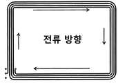
무선 전력 전송 시스템을 위한 하나의 공지된 코일 레이아웃은 기본 나선 루프(basic spiral loop)이다. 도 1은 기본 나선 루프 코일을 도시한다. 기본 나선 루프 코일에서, 코일의 인덕턴스(L)는 N2에 비례하며, 여기서 N은 코일의 턴 수이다. 이러한 유형의 코일은 일반적으로 20W 미만의 소형 저전력 시스템에 사용된다.One known coil layout for a wireless power transmission system is a basic spiral loop. 1 shows a basic spiral loop coil. In a basic spiral loop coil, the inductance (L) of the coil is proportional to N 2 , where N is the number of turns of the coil. Coils of this type are typically used in small, low power systems under 20W.
다른 공지된 코일 레이아웃은 기본 인터리브 나선 루프(basic interleaved spiral loop)이다. 도 2는 2 개의 인터리브 루프 권선을 포함하는 기본 인터리브 나선 루프 코일을 도시한다. 하나의 권선은 하나의 실선으로 도시된다. 다른 권선은 점선으로 도시된다. 도 2에서 두 권선은 높은 인덕턴스를 위해 직렬로 구성되거나 낮은 인덕턴스를 위해 병렬로 구성될 수 있다. 이러한 유형의 루프 코일은 일반적으로 무선 전력 송신기(즉, 전원 측)에서 사용된다. 도 2에 도시된 미러 이미지 패턴은 충전 표면에(코일로부터 특정 거리에) 거의 균일한 자기장을 제공한다. 이러한 유형의 루프 코일은 중간 전력 애플리케이션(최대 70W 시스템)에 사용된다. 코일의 물리적 크기는 대략 12 제곱인치로 제한된다.Another known coil layout is a basic interleaved spiral loop. Figure 2 shows a basic interleaved spiral loop coil comprising two interleaved loop windings. One winding is shown as one solid line. The other winding is shown in dotted lines. The two windings in FIG. 2 can be configured in series for high inductance or can be configured in parallel for low inductance. Loop coils of this type are commonly used in wireless power transmitters (ie, on the power side). The mirror image pattern shown in FIG. 2 provides a nearly uniform magnetic field to the filling surface (at a specific distance from the coil). This type of loop coil is used for medium power applications (up to 70W system). The physical size of the coil is limited to approximately 12 square inches.
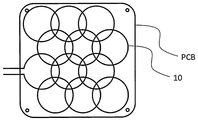
다른 코일 레이아웃은 2018년 3월 15일에 출원된 미국 특허 출원번호 제15/922,286호에 개시되어 있다. 일례는 도 3에 도시된 코일 레이아웃이다. 도 3은 PCB상의 다중 루프의 단일 코일(10)을 사용하여 형성된 코일 클러스터로 형성된 다중 루프를 도시한다. 단일 코일(10)은 복수의 원형 루프의 패턴을 형성하기 위해 PCB 상에 권취된다. 복수의 원형 루프들은 직렬로 연결되어 있다. 코일 클러스터는 복수의 원형 루프의 패턴을 유지하기 위해 제공되며, 루프는 수평 및 수직 방향으로 모두, 각각의 인접한 루프로부터 등거리에 있다. 이것은 코일 클러스터가 다른 코일 클러스터와 분리되도록 코일 클러스터가 중첩될 때 코일 루프의 패턴이 유지되게 만든다. 이것은 또한 연결된 코일 클러스터의 각각의 인접한 루프가 서로 분리되게 만든다. 이러한 루프의 분리를 통해, 직렬 연결된 작은 루프들의 조합으로 인한 인덕턴스는 동등한 크기의 권선 코일에 비해 비교적 낮다. 저 인덕턴스의 코일은 가상 임피던스 변화에 대한 환경의 영향이 적기 때문에 무선 전력 전송에 유리하다.Another coil layout is disclosed in U.S. Patent Application No. 15 / 922,286, filed March 15, 2018. An example is the coil layout shown in FIG. 3. 3 shows a multiple loop formed of a coil cluster formed using a
대면적에 전력을 제공하기 위해 사용될 때 이러한 무선 전력 시스템에 문제가 발생할 수 있다. 예를 들어, 코일 면적이 증가할수록, 방사되는 자기장의 부피가 증가하여 생체 조직으로의 비흡수율(SAR: specific absorption rate)이 증가하고 EMI 방사 수준이 증가하여 방사 방출 한계를 준수하는 것이 더 어려워질 수 있다.Problems can arise with such wireless power systems when used to provide power for large areas. For example, as the coil area increases, the volume of the emitted magnetic field increases, which increases the specific absorption rate (SAR) to biological tissue and increases the EMI radiation level, making it more difficult to comply with the emission limits. You can.
큰 코일 면적의 다른 효과는 인덕턴스의 증가이며, 따라서 6.78 MHz의 고 공진 무선 전력 애플리케이션을 위한 고정된 ISM(industrial, scientific and medical) 대역으로 코일을 튜닝하는 것은 항상 커패시턴스의 감소를 요구한다. 커패시턴스가 작을수록 허용 공차의 영향이 커지고, 이는 코일을 공진 유지하기 어렵고 생산에 실용적이지 않게 만든다. 높은 인덕턴스는 튜닝 커패시터 전체에 고전압 응력을 야기한다. 이 전압은 쉽게 1000V를 초과할 수 있다.Another effect of the large coil area is an increase in inductance, so tuning the coil to a fixed industrial, scientific and medical (ISM) band for high resonant wireless power applications at 6.78 MHz always requires a reduction in capacitance. The smaller the capacitance, the greater the effect of the tolerance, which makes it difficult to keep the coil resonant and impractical for production. The high inductance causes high voltage stress across the tuning capacitor. This voltage can easily exceed 1000V.
대면적 코일의 부수적 효과는 대면적 코일이 외부 금속 물체의 존재, 장치(부하)로부터의 용량성 커플링 및 부하 전력 요구와 같은 사용 사례 변화로 인한 가상 임피던스 시프팅에 더욱 민감해진다는 것이다.The side effect of the large area coil is that the large area coil becomes more sensitive to virtual impedance shifting due to use case changes such as the presence of external metal objects, capacitive coupling from the device (load), and load power demand.
다른 문제는 대면적 코일에 전형적으로 사용되는 고주파(6.78 MHz) 증폭기가, 더 높은 전압 및/또는 전류 FET를 사용할 때에도, 장치 전압 정격 및 설계 한계로 인해 최대 출력 전력에 제한을 갖는다는 것이다.Another problem is that the high frequency (6.78 MHz) amplifiers typically used in large area coils, even when using higher voltage and / or current FETs, have limitations in maximum output power due to device voltage ratings and design limitations.
따라서, 상기 문제를 해결하는 대면적 무선 전력 시스템을 제공할 필요성이 있다.Therefore, there is a need to provide a large area wireless power system that solves the above problems.
일 실시예에서, 복수의 코일을 포함하는 대면적 무선 전력 시스템이 제공된다. 장거리에 걸쳐 복수의 코일에 전력을 공급할 때 타이밍 왜곡과 지터(jitter)가 문제가 될 수 있기 때문에, 타이밍 왜곡과 지터를 줄이기 위해 동기화 회로가 제공된다. 동기화 회로는 또한 코일들에 제공된 신호들이 동위상이거나 적어도 임의의 최대 위상 지연 임계값 내에 있도록 신호 내 위상 지연을 보상할 수 있다. 신호들이 동위상임을 보장하는 것은 하나 이상의 코일로부터 전력을 수신할 수 있는 큰 부하에게 중요하다.In one embodiment, a large area wireless power system is provided that includes a plurality of coils. Synchronization circuitry is provided to reduce timing distortion and jitter because timing distortion and jitter can be a problem when powering multiple coils over long distances. The synchronization circuit can also compensate for the phase delay in the signal such that the signals provided to the coils are in-phase or at least within any maximum phase delay threshold. Ensuring that signals are in-phase is important for large loads that can receive power from one or more coils.
예시적인 실시예에서, 대면적 무선 전력 시스템은 동기화 송신기 및 동기화 송신기로부터 복수의 차동 신호를 수신하고 복수의 제 2 단일 종단 신호(single-ended signal)를 출력하기 위한 복수의 동기화 수신기를 갖는다. 동기화 송신기는 제 1 단일 종단 신호를 생성하고 제 1 단일 종단 신호를 복수의 차동 신호로 변환한다. 대면적 무선 전력 시스템은 또한 각각의 동기화 수신기로부터 복수의 제 2 단일 종단 신호를 수신하고 전력을 생성하기 위한 복수의 고전력 증폭기, 및 복수의 고전력 증폭기에 의해 생성된 전력을 수신하고 전력을 무선으로 제공하기 위한 복수의 무선 전력 코일을 포함한다.In an exemplary embodiment, the large area wireless power system has a synchronization transmitter and a plurality of synchronization receivers for receiving a plurality of differential signals from the synchronization transmitter and outputting a plurality of second single-ended signals. The synchronization transmitter generates a first single-ended signal and converts the first single-ended signal into a plurality of differential signals. The large area wireless power system also receives a plurality of second single-ended signals from each synchronization receiver and a plurality of high-power amplifiers for generating power, and receives power generated by the plurality of high-power amplifiers and provides power wirelessly It includes a plurality of wireless power coils.
다른 실시예에서, 대면적 무선 전력 시스템은 공진 대면적 코일, 더 작은 유도 코일 및 유도 코일에 전력을 공급하여 유도 코일이 공진 대면적 코일 내로 자기장을 유도하게 하기 위한 고전류 증폭기를 포함한다. 고전류 증폭기는, 예를 들어 전류 밸런싱 인덕터를 사용하여 병렬로 배열된 2 개의 차동 모드 ZVS 클래스 D 증폭기로서 구성될 수 있고 또는 병렬로 배열된 2 개의 차동 모드 클래스 E 증폭기로서 구성될 수 있다.In another embodiment, the large area wireless power system includes a resonant large area coil, a smaller induction coil, and a high current amplifier to power the induction coil so that the induction coil induces a magnetic field into the resonant large area coil. The high current amplifier may be configured as two differential mode ZVS class D amplifiers arranged in parallel using, for example, a current balancing inductor, or two differential mode class E amplifiers arranged in parallel.
다른 실시예에서, 대면적 무선 전력 시스템은 대면적 코일 및 대면적 코일에 전력을 제공하기 위한 고전압 증폭기를 포함한다. 고전압 증폭기는 멀티-레벨 구성으로 적층된 복수의 ZVS 클래스 D 증폭기를 포함하고, 각각의 ZVS 클래스 D 증폭기는 동기식으로 스위칭된다.In another embodiment, a large area wireless power system includes a large area coil and a high voltage amplifier to provide power to the large area coil. The high voltage amplifier includes a plurality of ZVS Class D amplifiers stacked in a multi-level configuration, and each ZVS Class D amplifier is switched synchronously.
또한, 무선 전력 코일에 고전력을 제공하는 증폭기 회로가 설명된다. 증폭기 회로는 차동 드라이버로부터 차동 신호를 수신하고 그 신호를 단일 종단 신호로 변환하기 위한 차동 수신기를 포함한다. 증폭기 회로는 단일 종단 신호를 수신하고 차동 수신기를 격리하기 위한 격리 드라이버 및 단일 종단 신호를 수신하고 무선 전력 코일에 전력을 제공하기 위한 고전력 증폭기를 더 포함한다. 증폭기 회로는 또한 신호가 고전력 증폭기에 제공되기 전에 단일 종단 신호 내의 임의의 위상 지연을 보상하기 위한 지연 보상 회로를 포함한다.Also described is an amplifier circuit that provides high power to the wireless power coil. The amplifier circuit includes a differential receiver for receiving the differential signal from the differential driver and converting the signal to a single-ended signal. The amplifier circuit further includes an isolation driver for receiving a single-ended signal and isolating the differential receiver and a high-power amplifier for receiving the single-ended signal and providing power to the wireless power coil. The amplifier circuit also includes a delay compensation circuit to compensate for any phase delay in the single-ended signal before the signal is provided to the high power amplifier.
또한, 복수의 전력 코일에 제공된 복수의 전력 신호를 동기화하기 위한 동기화 회로가 설명된다. 동기화 회로는 단일 종단 신호를 생성하는 발진기 및 단일 종단 신호를 복수의 차동 신호로 변환하기 위한 동기화 송신기를 포함한다. 동기화 회로는 동기화 송신기로부터 복수의 차동 신호를 수신하고 복수의 차동 신호를 복수의 동기화된 단일 종단 신호로 변환하기 위한 복수의 동기화 수신기를 더 포함한다. 동기화 회로는 또한 복수의 동기화된 단일 종단 신호 내의 위상 지연을 보상하기 위한 지연 보상 회로를 포함한다.Further, a synchronization circuit for synchronizing a plurality of power signals provided to a plurality of power coils is described. The synchronization circuit includes an oscillator generating a single-ended signal and a synchronization transmitter for converting the single-ended signal into a plurality of differential signals. The synchronization circuit further includes a plurality of synchronization receivers for receiving the plurality of differential signals from the synchronization transmitter and converting the plurality of differential signals into a plurality of synchronized single-ended signals. The synchronization circuit also includes a delay compensation circuit for compensating for phase delay in a plurality of synchronized single-ended signals.
본 발명의 다른 특징 및 장점은 첨부 도면과 함께 아래의 상세한 설명에 의해 더 명백해질 것이다.Other features and advantages of the present invention will become more apparent by the following detailed description in conjunction with the accompanying drawings.
도 1은 기본 나선 루프 코일을 도시한다.
도 2는 2 개의 인터리브 루프 권선을 포함하는 기본 인터리브 나선 루프 코일을 도시한다.
도 3은 공지된 다중 루프 코일 클러스터를 도시한다.
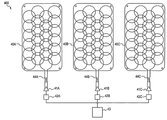
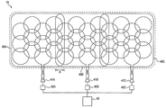
도 4는 일 실시예에 따른 대면적 무선 전력 시스템을 도시한다.
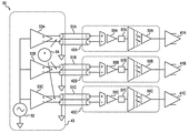
도 5는 일 실시예에 따른 동기화 회로를 도시한다.
도 6은 일 실시예에 따른 지연 보상 회로를 도시한다.
도 7은 대면적 무선 전력 시스템의 일 실시예를 도시한다.
도 8은 대면적 무선 전력 시스템의 일 실시예를 도시한다.
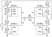
도 9는 병렬 고전류 ZVS 클래스 D 증폭기의 일 실시예를 도시한다.
도 10은 병렬 고전류 ZVS 클래스 E 증폭기의 일 실시예를 도시한다.
도 11은 대면적 무선 전력 시스템의 일 실시예를 도시한다.
도 12는 고 전압 멀티-레벨 ZVS 클래스 D 증폭기의 일 실시예를 도시한다.1 shows a basic spiral loop coil.
Figure 2 shows a basic interleaved spiral loop coil comprising two interleaved loop windings.
3 shows a known multi-loop coil cluster.
4 illustrates a large area wireless power system according to an embodiment.
5 shows a synchronization circuit according to an embodiment.
6 illustrates a delay compensation circuit according to an embodiment.
7 shows an embodiment of a large area wireless power system.
8 shows an embodiment of a large area wireless power system.
9 shows an embodiment of a parallel high current ZVS Class D amplifier.
10 shows an embodiment of a parallel high current ZVS Class E amplifier.
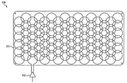
11 shows an embodiment of a large area wireless power system.
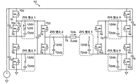
12 shows an embodiment of a high voltage multi-level ZVS class D amplifier.
도 4는 본 발명의 제 1 실시예에 따른 대면적 무선 전력 시스템(400)을 도시한다. 무선 전력 시스템(400)은 3 개의 코일(40A, 40B, 40C)을 갖지만, 전력을 제공하는 면적의 크기에 기초하여 더 많거나 적은 코일이 사용될 수 있다. 도 4 및 아래의 도면은 도 3의 다중 루프 구성을 도시하지만, 코일(40A, 40B 및 40C)은 임의의 코일 유형일 수 있다. 각각의 코일은 각각의 무선 전력 증폭기(41A, 41B, 41C)에 연결된다. 코일(40A, 40B, 40C)은 개별 단계에서 스케일링(scale)되지만, 2 개 이상의 코일에 연결할 만큼 충분히 큰 임의의 부하가 각 코일로부터 동위상의 전력을 수신함을 보장하기 위해 각 무선 전력 증폭기(41A, 41B, 41C) 간의 정확한 동기화가 필요하다. 그러나, 무선 전력 증폭기들 간의 물리적 거리는 낮은 지터 및 타이밍 왜곡을 갖는 동기 신호를 분배하는 것을 어렵게 만든다. 이와 관련하여, 각각의 무선 전력 증폭기는 동기화 수신기(42A, 42B, 42C) 및 동기화 송신기(43)를 포함하는 동기화 회로(50)에 연결된다. 또한, 이 실시예에서, 코일(40A, 40B, 40C)은 -17 dB의 최대 결합을 갖도록 하는 방식으로 물리적으로 이격된다.4 shows a large area
고 공진 무선 전력 애플리케이션을 위한 ISM 주파수 6.78 MHz에서, 코일 클러스터의 대면적은 그들 사이의 용량성 커플링을 증가시킨다. 이 용량성 커플 링은 공통 모드 전류를 위한 경로를 제공한다. 공통 모드 전류는 EMI 문제, 원치 않는 가열 및 성능 저하를 야기한다. 이러한 공통 모드 문제를 극복하기 위해, 적합한 공통 모드 초크(44A, 44B, 44C)는 무선 전력 증폭기(41A, 41B, 41C)와 코일(40A, 40B, 40C) 사이에 연결된다. 공통 모드 초크(44A, 44B, 44C)는 바람직하게는 바이필라 권선이고(bifilar wound), 바람직하게는 두꺼운 플라스틱 절연체를 사용하여 커패시턴스를 감소시켜 코어 재료에 직접적으로 손실을 유도한다.At 6.78 MHz ISM frequency for high resonant wireless power applications, the large area of the coil cluster increases the capacitive coupling between them. This capacitive coupling provides a path for common mode current. Common-mode currents cause EMI problems, unwanted heating, and poor performance. To overcome this common mode problem, suitable common mode chokes 44A, 44B, 44C are connected between
도 5는 바람직한 실시예에 따라 동기화 회로(50)를 함께 포함하는, 도 4의 동기화 송신기(43) 및 동기화 수신기(42A, 42B, 42C)의 블록도를 도시한다. 동기화 회로(50)는 차동 전송 라인 쌍(51A, 51B, 51C)에 의해 복수의 동기화 수신기(42A, 42B, 42C)에 연결된 동기화 송신기(43)를 포함한다. 동기화 송신기(43)는 무선 전력 시스템(400)에 단일 종단 클록 신호를 제공하는 발진기(52), 단일 종단 클록 신호를 차동 신호로 변환하는 차동 드라이버(53A, 53B, 53C) 및 각각의 차동 전송 라인 쌍(51A, 51B, 51C)에 전력을 제공하는 DC 전원(54)을 포함한다. 발진기(52)에 의해 공급되는 신호의 주파수는 바람직하게는 고 공진 무선 전력 애플리케이션을 위한 ISM 대역인 6.78 MHz이다. 각각의 동기화 수신기(42A, 42B, 42C)는 격리 드라이버(56A, 56B, 56C)에 연결된 차동 수신기(55A, 55B, 55C)를 포함한다.5 shows a block diagram of
차동 전송 라인 쌍(51A, 51B, 51C)은 발진기(52)로부터 각각의 차동 수신기(55A, 55B, 55C)로 클록 신호를 분배하기 위해 사용된다. 차동 전송 라인 쌍(51A, 51B, 51C)은 무선 전력 전자기장으로부터의 내성을 제공하기 위해 사용되고 지터 및 타이밍 에러를 유발할 수 있는 반사를 방지하는 고정 임피던스, 바람직하게는 50Ω 또는 100 Ω를 갖는다. 각각의 동기화 수신기(42A, 42B, 42C)는 각각의 차동 전송 라인 쌍(51A, 51B, 51C)으로부터 차동 신호를 수신하고 그 차동 신호를 각각의 무선 전력 증폭기(41A, 41B, 41C)에 연결된 격리 드라이버(56A, 56B, 56C)의 형태로, 격리 장벽을 통해 전송되는 단일 종단 신호로 변환한다. 각각의 차동 수신기(55A, 55B, 55C)의 출력은 각각의 무선 전력 증폭기(41A, 41B, 41C) 사이의 고주파 저임피던스 경로를 제거하기 위해 격리 된 드라이버(56A, 56B, 56C)에 공급된다. 각각의 차동 수신기(55A, 55B, 55C)는 바람직하게는 각각의 차동 전송 라인 쌍(51A, 51B, 51C)을 통해 DC 전원(54)으로부터의 DC 전력을 수신한다. 각각의 격리 된 드라이버는 바람직하게는 각각의 무선 전력 증폭기(41A, 41B, 41C)에 의해 전력을 공급 받는다.Differential transmission line pairs 51A, 51B, 51C are used to distribute the clock signal from the
복수의 코일이 동기화될 때, 다양한 길이의 케이블이 필요하다. 그러나, 길이가 상이한 케이블을 사용하면, 각 수신기에서의 다른 신호와 비교하여 위상차가 발생할 수 있다. 전술한 바와 같이, 다양한 코일들이 동위상인 것이 중요하다. 이 문제를 해결하는 한 가지 방법은 동기화 송신기를 동기화 수신기에 연결하는데 동일한 길이의 케이블을 사용하는 것이다. 그러나, 송신기와 수신기 사이의 거리가 짧은 코일의 경우, 케이블의 다발화를 야기할 수 있고, 이것은 다발화된 케이블을 보관할 공간을 필요로 한다. 따라서, 이 솔루션은 바람직하지 않다. 다른 솔루션은 도 5에 도시된 바와 같이 각각의 동기화 회로에 지연 보상 회로(57A, 57B, 57C)를 포함하는 것이다. 케이블이 가장 짧은 경우 지연 보상 회로는 더 긴 지연을 추가하도록 구성될 수 있다. 케이블이 중간 길이인 경우 지연 보상 회로는 중간 지연을 추가하도록 구성될 수 있다. 케이블이 가장 긴 경우 지연 보상 회로는 필요하지 않으며, 모든 지연 회로 설정에 대한 지연 기준으로서의 역할을 수행한다. 모든 추가된 지연들은 각각의 수신기에 대한 다양한 신호들 간의 최소 위상차의 목표, 바람직하게는 200 ps 이하를 달성하도록 의도된다.When multiple coils are synchronized, cables of various lengths are required. However, if cables of different lengths are used, a phase difference may occur compared to other signals at each receiver. As mentioned above, it is important that the various coils are in phase. One way to solve this problem is to use the same length of cable to connect the sync transmitter to the sync receiver. However, in the case of a coil having a short distance between the transmitter and the receiver, it may cause a bundle of cables, which requires space for storing the bundled cables. Therefore, this solution is not desirable. Another solution is to include
지연 보상 회로(57A, 57B, 57C)는 도 5에 도시된 바와 같이 차동 수신기(55A, 55B, 55C)와 격리 드라이버(56A, 56B, 56C) 사이에 배치되는 것이 바람직하다. 또한, 지연 보상 회로(57A, 57B, 57C)는 격리 드라이버(56A, 56B, 56C) 뒤에 그리고 무선 전력 증폭기(41A, 41B, 41C) 이전에 배치될 수도 있고, 또는 발진기(52)와 동기화 송신기(43)의 차동 드라이버(53A, 53B, 53C) 사이에 배치될 수도 있다. 도 6은 예시적인 지연 보상 회로(57A, 57B, 57C)를 도시하고, 예시적인 지연 보상 회로가 지연을 보상하기 위해 동작하는 방법을 그래프로 도시한다. 도 6에 도시된 지연 보상 회로는 예시적인 것이며, 임의의 공지된 지연 보상 회로가 사용될 수 있다.The
도 7은 무선 전력 시스템(70)을 갖는 본 발명의 대안의 실시예를 도시한다. 무선 전력 시스템(70)은 코일(40A, 40B, 40C)이 미국 특허 출원 번호 제 15/922,286호에 기술된 바와 같이 부분적으로 중첩한다는 점을 제외하고는 무선 전력 시스템(400)(도 4)과 거의 동일하다.7 shows an alternative embodiment of the invention with a
도 8은 다른 실시예에 따른 대면적 무선 전력 시스템(80)을 도시한다. 대면적 무선 전력 시스템(80)은 공진 대면적 코일(81) 및 더 작은 유도 코일(82)을 사용한다. 고 전류 증폭기(83)에 의해 구동되는 더 작은 유도 코일(82)은 공진 대면적 코일(81) 내로 자기장을 유도하고, 공진을 통해 자기장을 강화시킨다. 더 작은 유도 코일(82)은 고전류 1 차이다, 즉, 공진 대면적 코일(81) 내에 고 전력을 유도하기 위한 전류는 더 작은 유도 코일에 대해 높은 전류를 야기하고 전류 변환기처럼 행동한다. 더 작은 유도 코일(82)은 튜닝될 수도 있고 튜닝되지 않을 수도 있다. 공진 대면적 코일(81)은 저 전류 코일이며 튜닝된다.8 shows a large area
대면적 무선 전력 시스템(80) 내의 2 개의 코일(81, 82)의 조합은 정확한 전류를 생성하기 위한 전류 변환기로서의 역할을 수행한다. 도 4의 대면적 무선 전력 시스템(400)에 비해 대면적 무선 전력 시스템(80)의 2-코일 접근법의 주요 이점은 공진 대면적 코일(81)이 전력 표면적 위에 주기적인 작은 갭 없이 균일한 필드를 생성하도록 설계될 수 있다는 것이다. 그러나, 대면적 무선 전력 시스템(80)의 2-코일 접근법은 유도 코일 면적의 증가로 인해 매우 넓은 면적으로 스케일링될 수 있는 능력이 제한되어 있다. 또한, 유도 코일과 공진 코일 모두 대면적에 적합한 특성을 가져야 한다.The combination of the two
고전류 증폭기(83)는, 예를 들어, 차동 모드 ZVS 클래스 D 증폭기 또는 도 10에 도시된 바와 같이 병렬로 배열된 2 개의 차동 모드 클래스 E 증폭기 사이의 순환 전류를 방지하기 위해, 도 9에 도시된 바와 같이 전류 밸런싱 인덕터(LB1, LB2, LB2, LB4)를 사용하여 병렬로 배열된 2 개의 차동 모드 ZVS 클래스 D 증폭기 일 수 있다. 이 두 경우 모두 전류를 증가시켜 코일로의 전력을 증가시킨다. 이러한 병렬 증폭기는 미국 특허 제 9,331,061 호에 보다 상세하게 기술되어있다. 도 9 및 도 10의 각각의 증폭기 토폴로지에 사용된 각각의 FET에 대한 게이트 신호 타이밍은 또한 손실 증가로 이어질 수 있는 전류 불균형 또는 순환을 방지하기 위해 정확한 타이밍을 요구한다. 이것은 지연 보상 회로(57A, 57B, 57C)와 유사한 방식으로 신호가 좁은 윈도우 내에 도달하도록, 동등한 신호 전송 경로 길이와 함께 저 지연 게이트 드라이버가 사용될 것을 요구한다.The high
도 11은 다른 실시예에 따른 대면적 무선 전력 시스템(110)을 도시한다. 대면적 무선 전력 시스템(110)은 고전압 증폭기(112)에 의해 전력을 공급받는 하나의 대형 코일(111)만을 사용한다. 무선 전력 시스템(110)은 코일에 충분한 전류를 유도하기에 충분한 구동 전압을 제공함으로써 대형 코일과 관련된 문제를 극복한다.11 shows a large area
도 12는 고전압 증폭기(112)의 예시적인 실시예를 도시한다. 고전압 증폭기(112)는 멀티-레벨 구성으로 적층된 복수의 ZVS 클래스 D 증폭기를 포함하며, 여기서 모든 증폭기는 동기식으로 스위칭될 필요가 있다. 멀티-레벨 변환기에 고유하게, 고전압 증폭기(112)는 더 낮은 스위칭 주파수를 허용하면서 부하에 대한 출력 주파수를 증가시킨다. 이것은 이러한 토폴로지의 많은 장치에 대한 손실을 낮게 유지한다. 이 토폴로지는 ZVS 클래스 D 토폴로지가 각 개별 레벨(하프 브리지)에 대한 ZVS를 보장하는데 사용되는 멀티-레벨 변환기로 확장된다. 도 12는 차동 모드 구성을 도시하지만, 고전압 증폭기(112)는 단일 종단형일 수도 있다.12 shows an exemplary embodiment of a
상기 상세한 설명에서, 특정 실시예가 참조된다. 이 실시예들은 당업자가 실시할 수 있도록 충분히 상세하게 설명된다. 다른 실시예들이 이용될 수 있고 다양한 구조적, 논리적 및 전기적 변경이 이루어질 수 있음을 이해해야 한다. 또한, 특정 실시예가 에너지 전달 시스템과 관련지어 설명되었지만, 여기에 설명된 특징은 일반적으로 다른 유형의 회로에 적용 가능하다는 것을 이해해야 한다.In the above detailed description, specific embodiments are referred to. These embodiments are described in sufficient detail to enable those skilled in the art to practice. It should be understood that other embodiments can be used and various structural, logical and electrical modifications can be made. Further, although certain embodiments have been described in connection with energy delivery systems, it should be understood that the features described herein are generally applicable to other types of circuits.
Claims (21)
제 1 단일 종단 신호를 생성하고 상기 제 1 단일 종단 신호를 복수의 차동 신호로 변환하는 동기화 송신기;
상기 동기화 송신기로부터 상기 복수의 차동 신호를 수신하고 복수의 제 2 단일 종단 신호를 출력하는 복수의 동기화 수신기;
상기 동기화 수신기 각각으로부터 상기 복수의 제 2 단일 종단 신호를 수신하고 전력을 생성하기 위한 복수의 고전력 증폭기; 및
상기 복수의 고전력 증폭기에 의해 생성된 전력을 수신하고 무선으로 전력을 제공하기 위한 복수의 무선 전력 코일을 포함하는 것을 특징으로 하는, 대면적 무선 전력 시스템.
As a large area wireless power system,
A synchronization transmitter for generating a first single-ended signal and converting the first single-ended signal into a plurality of differential signals;
A plurality of synchronization receivers receiving the plurality of differential signals from the synchronization transmitter and outputting a plurality of second single-ended signals;
A plurality of high-power amplifiers for receiving the plurality of second single-ended signals from each of the synchronization receivers and generating power; And
And a plurality of wireless power coils for receiving power generated by the plurality of high power amplifiers and providing power wirelessly.
상기 동기화 송신기는,
상기 제 1 단일 종단 신호를 생성하는 발진기; 및
상기 제 1 단일 종단 신호를 수신하고 상기 복수의 차동 신호를 생성하기 위한 복수의 차동 드라이버를 포함하는 것을 특징으로 하는, 대면적 무선 전력 시스템.
According to claim 1,
The synchronization transmitter,
An oscillator generating the first single-ended signal; And
And a plurality of differential drivers for receiving the first single-ended signal and generating the plurality of differential signals.
상기 복수의 차동 신호를 상기 동기화 송신기로부터 상기 복수의 동기화 수신기로 전달하기 위한 복수의 차동 케이블을 더 포함하는 것을 특징으로 하는, 대면적 무선 전력 시스템.
According to claim 1,
And a plurality of differential cables for transmitting the plurality of differential signals from the synchronization transmitter to the plurality of synchronization receivers.
각각의 동기화 수신기는,
상기 복수의 차동 신호를 상기 복수의 단일 종단 신호로 변환하기 위한 차동 수신기; 및
상기 단일 종단 신호를 수신하고 상기 고전력 증폭기 각각으로부터 상기 동기화 수신기를 격리하기 위한 격리 드라이버를 포함하는 것을 특징으로 하는, 대면적 무선 전력 시스템.
The method of claim 3,
Each sync receiver,
A differential receiver for converting the plurality of differential signals into the plurality of single-ended signals; And
And an isolation driver for receiving the single-ended signal and isolating the synchronization receiver from each of the high-power amplifiers.
각각의 차동 수신기는 상기 복수의 차동 케이블 중 각각의 차동 케이블부터 전력을 수신하는 것을 특징으로 하는, 대면적 무선 전력 시스템.
The method of claim 4,
Each differential receiver receives power from each differential cable among the plurality of differential cables, a large area wireless power system.
상기 복수의 동기화 수신기 각각은 상기 제 2 단일 종단 신호 내의 임의의 위상 지연을 보상하기 위한 지연 보상 회로를 더 포함하는 것을 특징으로 하는, 대면적 무선 전력 시스템.
According to claim 1,
Each of the plurality of synchronization receivers further comprises a delay compensation circuit for compensating for any phase delay in the second single-ended signal, large area wireless power system.
상기 지연 보상 회로는 상기 차동 수신기로부터 상기 단일 종단 신호를 수신하고 위상 지연 보상된 신호를 상기 격리 드라이버에 제공하는 것을 특징으로 하는, 대면적 무선 전력 시스템.
The method of claim 6,
And the delay compensation circuit receives the single-ended signal from the differential receiver and provides a phase delay-compensated signal to the isolation driver.
상기 지연 보상 회로는 상기 격리 드라이버로부터 상기 단일 종단 신호를 수신하고 위상 지연 보상된 신호를 상기 고전력 증폭기에 제공하는 것을 특징으로 하는, 대면적 무선 전력 시스템.
The method of claim 6,
And the delay compensation circuit receives the single ended signal from the isolation driver and provides a phase delay compensated signal to the high power amplifier.
차동 드라이버로부터 차동 신호를 수신하고 그 신호를 단일 종단 신호로 변환하는 차동 수신기;
상기 단일 종단 신호를 수신하고 상기 차동 수신기를 격리하기 위한 격리 드라이버;
상기 단일 종단 신호를 수신하고 상기 무선 전력 코일에 전력을 제공하기 위한 고전력 증폭기; 및
신호가 상기 고전력 증폭기에 제공되기 전에 상기 단일 종단 신호 내의 임의의 위상 지연을 보상하기 위한 지연 보상 회로를 포함하는 것을 특징으로 하는, 증폭기 회로.
As an amplifier circuit for supplying high power to the wireless power coil,
A differential receiver that receives a differential signal from the differential driver and converts the signal to a single-ended signal;
An isolation driver for receiving the single-ended signal and isolating the differential receiver;
A high power amplifier for receiving the single-ended signal and providing power to the wireless power coil; And
And a delay compensation circuit for compensating for any phase delay in the single ended signal before a signal is provided to the high power amplifier.
상기 지연 보상 회로는 상기 차동 수신기로부터 상기 단일 종단 신호를 수신하고 위상 지연 보상된 신호를 상기 격리 드라이버에 제공하는 것을 특징으로 하는, 증폭기 회로.
The method of claim 9,
And the delay compensation circuit receives the single ended signal from the differential receiver and provides a phase delay compensated signal to the isolation driver.
상기 지연 보상 회로는 상기 격리 드라이버로부터 상기 단일 종단 신호를 수신하고 위상 지연 보상된 신호를 상기 고전력 증폭기에 제공하는 것을 특징으로 하는, 증폭기 회로.
The method of claim 9,
And the delay compensation circuit receives the single ended signal from the isolation driver and provides a phase delay compensated signal to the high power amplifier.
단일 종단 신호를 생성하고 상기 단일 종단 신호를 복수의 차동 신호로 변환하는 동기화 송신기;
상기 동기화 송신기로부터 상기 복수의 차동 신호를 수신하고 상기 복수의 차동 신호를 복수의 동기화된 단일 종단 신호로 변환하는 복수의 동기화 수신기; 및
복수의 동기화된 단일 종단 신호 내의 위상 지연을 보상하기 위한 지연 보상 회로를 포함하는 것을 특징으로 하는, 동기화 회로.
A synchronization circuit for synchronizing a plurality of power signals provided to a plurality of power coils,
A synchronization transmitter that generates a single-ended signal and converts the single-ended signal into a plurality of differential signals;
A plurality of synchronization receivers receiving the plurality of differential signals from the synchronization transmitter and converting the plurality of differential signals into a plurality of synchronized single-ended signals; And
And a delay compensation circuit for compensating for phase delay in a plurality of synchronized single-ended signals.
상기 동기화 송신기는,
상기 단일 종단 신호를 생성하기 위한 발진기; 및
상기 단일 종단 신호를 수신하고 상기 복수의 차동 신호를 생성하기 위한 복수의 차동 드라이버를 포함하며,
상기 복수의 차동 신호를 상기 동기화 송신기로부터 상기 복수의 동기화 수신기로 전달하기 위한 복수의 차동 케이블을 더 포함하는 것을 특징으로 하는, 동기화 회로.
The method of claim 12,
The synchronization transmitter,
An oscillator for generating the single-ended signal; And
A plurality of differential drivers for receiving the single-ended signal and generating the plurality of differential signals,
And a plurality of differential cables for transmitting the plurality of differential signals from the synchronization transmitter to the plurality of synchronization receivers.
각각의 동기화 수신기는,
상기 복수의 차동 신호 중 각각의 차동 신호를 상기 복수의 동기화된 단일 종단 신호 각각으로 변환하기 위한 차동 수신기; 및
상기 복수의 동기화된 단일 종단 신호 각각을 수신하고 상기 고전력 증폭기로부터 상기 동기화 수신기를 격리하기 위한 격리 드라이버를 포함하는 것을 특징으로 하는, 동기화 회로.
The method of claim 12,
Each sync receiver,
A differential receiver for converting each of the plurality of differential signals to each of the plurality of synchronized single-ended signals; And
And an isolation driver for receiving each of the plurality of synchronized single-ended signals and isolating the synchronization receiver from the high power amplifier.
상기 지연 보상 회로는 상기 차동 수신기로부터 상기 동기화된 단일 종단 신호를 수신하고 위상 지연 보상된 신호를 상기 격리 드라이버에 제공하는 것을 특징으로 하는, 동기화 회로.
The method of claim 12,
And the delay compensation circuit receives the synchronized single-ended signal from the differential receiver and provides a phase delay compensated signal to the isolation driver.
상기 지연 보상 회로는 상기 격리 드라이버로부터 상기 동기화된 단일 종단 신호를 수신하고 위상 지연 보상된 신호를 상기 고출력 증폭기에 제공하는 것을 특징으로 하는, 동기화 회로.
The method of claim 12,
And the delay compensation circuit receives the synchronized single ended signal from the isolation driver and provides a phase delay compensated signal to the high power amplifier.
상기 지연 보상 회로는 상기 발진기로부터 상기 단일 종단 신호를 수신하고 위상 지연 보상 신호를 상기 복수의 차동 드라이버에 제공하는 것을 특징으로 하는, 동기화 회로.
The method of claim 12,
And the delay compensation circuit receives the single-ended signal from the oscillator and provides a phase delay compensation signal to the plurality of differential drivers.
공진 대면적 코일;
유도 코일; 및
상기 유도 코일에 전력을 공급하여 상기 유도 코일이 상기 공진 대면적 코일 내에 자기장을 유도하게 하는 고전류 증폭기를 포함하는 것을 특징으로 하는, 대면적 무선 전력 시스템.
As a large area wireless power system,
Resonant large area coil;
induction coil; And
And a high current amplifier supplying power to the induction coil to induce the magnetic field in the resonant large area coil.
상기 고전류 증폭기는 차동 모드 ZVS 클래스 D 증폭기들 간의 순환 전류를 방지하기 위해 전류 밸런싱 인덕터를 사용하여 병렬로 배열된 2 개의 차동 모드 ZVS 클래스 D 증폭기로 구성된 것을 특징으로 하는, 대면적 무선 전력 시스템.
The method of claim 18,
The high current amplifier comprises two differential mode ZVS class D amplifiers arranged in parallel using a current balancing inductor to prevent circulating current between differential mode ZVS class D amplifiers, large area wireless power system.
상기 고전류 증폭기는 병렬로 배열된 2 개의 차동 모드 클래스 E 증폭기로 구성된 것을 특징으로 하는, 대면적 무선 전력 시스템.
The method of claim 18,
The high current amplifier comprises two differential mode class E amplifiers arranged in parallel, a large area wireless power system.
대면적 코일; 및
상기 대면적 코일에 전력을 제공하는 고전압 증폭기를 포함하고,
상기 고전압 증폭기는 멀티-레벨 구성으로 적층된 복수의 ZVS 클래스 D 증폭기를 갖고, 상기 복수의 ZVS 클래스 D 증폭기 각각은 동기식으로 스위칭되는 것을 특징으로 하는, 대면적 무선 전력 시스템.As a large area wireless power system,
Large area coils; And
And a high voltage amplifier providing power to the large area coil,
The high voltage amplifier has a plurality of ZVS Class D amplifiers stacked in a multi-level configuration, wherein each of the plurality of ZVS Class D amplifiers is characterized in that the synchronous switching, large area wireless power system.
Applications Claiming Priority (3)
| Application Number | Priority Date | Filing Date | Title |
|---|---|---|---|
| US201762550920P | 2017-08-28 | 2017-08-28 | |
| US62/550,920 | 2017-08-28 | ||
| PCT/US2018/048152 WO2019046194A1 (en) | 2017-08-28 | 2018-08-27 | Multi-coil large area wireless power system |
Publications (2)
| Publication Number | Publication Date |
|---|---|
| KR20200041372A true KR20200041372A (en) | 2020-04-21 |
| KR102578392B1 KR102578392B1 (en) | 2023-09-14 |
Family
ID=65435626
Family Applications (1)
| Application Number | Title | Priority Date | Filing Date |
|---|---|---|---|
| KR1020207008662A Active KR102578392B1 (en) | 2017-08-28 | 2018-08-27 | Multi-coil large-area wireless power system |
Country Status (7)
| Country | Link |
|---|---|
| US (1) | US10892650B2 (en) |
| EP (1) | EP3676934B1 (en) |
| JP (1) | JP7209696B2 (en) |
| KR (1) | KR102578392B1 (en) |
| CN (1) | CN111052539B (en) |
| TW (1) | TWI679823B (en) |
| WO (1) | WO2019046194A1 (en) |
Families Citing this family (14)
| Publication number | Priority date | Publication date | Assignee | Title |
|---|---|---|---|---|
| US11909226B2 (en) | 2019-05-21 | 2024-02-20 | General Electric Company | Wireless power transmission apparatus with multiple primary coils and adjacent coil muting |
| CN112701802A (en) * | 2020-11-19 | 2021-04-23 | 国网浙江省电力有限公司宁波供电公司 | Wireless charging system and method for robot |
| US11962337B2 (en) | 2021-11-03 | 2024-04-16 | Nucurrent, Inc. | Communications demodulation in wireless power transmission system having an internal repeater |
| US11824373B2 (en) * | 2021-11-03 | 2023-11-21 | Nucurrent, Inc. | Wireless power transmission antenna with parallel coil molecule configuration |
| US11862991B2 (en) | 2021-11-03 | 2024-01-02 | Nucurrent, Inc. | Wireless power transmission antenna with internal repeater and in-coil tuning |
| US11831175B2 (en) | 2021-11-03 | 2023-11-28 | Nucurrent, Inc. | Wireless power transmission antenna with antenna molecules |
| US11824371B2 (en) | 2021-11-03 | 2023-11-21 | Nucurrent, Inc. | Wireless power transmission antenna with internal repeater and repeater filter |
| US11831176B2 (en) | 2021-11-03 | 2023-11-28 | Nucurrent, Inc. | Wireless power transfer systems with substantial uniformity over a large area |
| US11848566B2 (en) | 2021-11-03 | 2023-12-19 | Nucurrent, Inc. | Dual communications demodulation of a wireless power transmission system having an internal repeater |
| US11824372B2 (en) | 2021-11-03 | 2023-11-21 | Nucurrent, Inc. | Wireless power transmission antenna with puzzled antenna molecules |
| US11862984B2 (en) | 2021-11-03 | 2024-01-02 | Nucurrent, Inc. | Wireless power receiver with repeater for enhanced power harvesting |
| US11831177B2 (en) * | 2021-11-03 | 2023-11-28 | Nucurrent, Inc. | Wireless power transmitter with internal repeater and enhanced uniformity |
| US12027880B2 (en) | 2021-11-03 | 2024-07-02 | Nucurrent, Inc. | Wireless power transfer from mouse pad to mouse |
| US11831173B2 (en) | 2021-11-03 | 2023-11-28 | Nucurrent, Inc. | Wireless power transmission antenna with series coil molecule configuration |
Citations (5)
| Publication number | Priority date | Publication date | Assignee | Title |
|---|---|---|---|---|
| JP2011199975A (en) * | 2010-03-18 | 2011-10-06 | Nec Corp | Device, system and method for noncontact power transmission |
| WO2013129859A1 (en) * | 2012-02-28 | 2013-09-06 | 한국전기연구원 | Wireless power transmission end including wireless power transmission network |
| KR20150063081A (en) * | 2012-09-28 | 2015-06-08 | 퀄컴 인코포레이티드 | Systems and methods for detecting wireless charging transmit characteristics |
| US20150236844A1 (en) * | 2014-02-19 | 2015-08-20 | Delta Electronics (Shanghai) Co., Ltd. | Synchronization signal transmitting device, method thereof and power electronic apparatus having the device |
| US20160111894A1 (en) * | 2014-03-25 | 2016-04-21 | Broadcom Corporation | Power transmitting unit and power receiving unit with control data communication and methods for use therewith |
Family Cites Families (29)
| Publication number | Priority date | Publication date | Assignee | Title |
|---|---|---|---|---|
| BRPI0408255A (en) * | 2003-03-12 | 2006-03-01 | Joule Microsystems Canada Inc | signal processing system and method |
| US8629650B2 (en) | 2008-05-13 | 2014-01-14 | Qualcomm Incorporated | Wireless power transfer using multiple transmit antennas |
| CA2757623A1 (en) | 2009-04-08 | 2010-10-14 | Access Business Group International Llc | Selectable coil array |
| US8772975B2 (en) * | 2009-12-07 | 2014-07-08 | Qualcomm Incorporated | Apparatus and method for implementing a differential drive amplifier and a coil arrangement |
| TWI493825B (en) * | 2013-02-04 | 2015-07-21 | Fu Da Tong Technology Co Ltd | Operating clock synchronization adjusting method and synchronous data transmitting for wireless power system |
| US8693961B2 (en) * | 2011-08-11 | 2014-04-08 | Intel IP Corporation | System and method for improving power efficiency of a transmitter |
| WO2013032906A1 (en) | 2011-08-29 | 2013-03-07 | Efficient Power Conversion Corporation | Parallel connection methods for high performance transistors |
| HK1200602A1 (en) * | 2011-11-04 | 2015-08-07 | WiTricity公司 | Wireless energy transfer modeling tool |
| US9270342B2 (en) * | 2011-12-16 | 2016-02-23 | Qualcomm Incorporated | System and method for low loss wireless power transmission |
| JP5696716B2 (en) * | 2012-02-28 | 2015-04-08 | 横河電機株式会社 | Wireless communication system, wireless communication method, and wireless access point device |
| KR101455697B1 (en) * | 2012-02-28 | 2014-11-03 | 한국전기연구원 | A wireless power transmitter including wireless power transmission network |
| JP5967989B2 (en) | 2012-03-14 | 2016-08-10 | ソニー株式会社 | Detecting device, power receiving device, power transmitting device, and non-contact power feeding system |
| CN102638113B (en) | 2012-04-11 | 2014-08-27 | 华中科技大学 | Magnetic coupling resonance device |
| US20140191568A1 (en) | 2013-01-04 | 2014-07-10 | Mojo Mobility, Inc. | System and method for powering or charging multiple receivers wirelessly with a power transmitter |
| US9929776B2 (en) * | 2013-03-15 | 2018-03-27 | Keyssa, Inc. | Physical layer adapted for EHF contactless communication |
| KR102155371B1 (en) * | 2013-09-09 | 2020-09-11 | 삼성전자주식회사 | Method and apparatus of wireless power transmission for cancelling harmonics noise |
| JP6432366B2 (en) * | 2014-03-31 | 2018-12-05 | Tdk株式会社 | Coil for wireless power transmission and wireless power transmission device |
| WO2015171910A1 (en) | 2014-05-07 | 2015-11-12 | Witricity Corporation | Foreign object detection in wireless energy transfer systems |
| US9762090B2 (en) * | 2014-09-24 | 2017-09-12 | Avago Technologies General Ip (Singapore) Pte. Ltd. | High efficiency gate driver for wireless power transmission |
| KR102266465B1 (en) * | 2015-01-29 | 2021-06-17 | 삼성전자주식회사 | Apparatus and method for controlling differential signals of wireless power transmitter |
| US10566839B2 (en) | 2015-06-30 | 2020-02-18 | WiTricinity Corporation | Systems, methods and apparatus for guidance and alignment between electric vehicles and wireless charging systems |
| KR102483302B1 (en) * | 2015-09-18 | 2022-12-30 | 삼성전자주식회사 | Wireless power receiver, wireless power transmitter and circuit for correcting differential signal |
| US10680465B2 (en) * | 2015-09-25 | 2020-06-09 | Samsung Electronics Co., Ltd. | Wireless power transmitter |
| US20170149282A1 (en) * | 2015-11-24 | 2017-05-25 | Qualcomm Incorporated | Wireless power transfer receiver having synchronous rectifier synchronized to wireless power transfer signal |
| US10361586B2 (en) * | 2015-12-29 | 2019-07-23 | Motorola Solutions, Inc. | Method of wirelessly transferring power |
| CN205486756U (en) * | 2016-01-21 | 2016-08-17 | 中国矿业大学(北京) | A wireless power and information synchronization transmission system for seismic prospecting |
| CN106130105A (en) * | 2016-07-11 | 2016-11-16 | 深圳天珑无线科技有限公司 | Wireless charging device, system and method |
| CN206237208U (en) | 2016-12-08 | 2017-06-09 | 佑骅科技(深圳)有限公司 | A kind of multi-coil multiplexing type wireless power reception device |
| US10250065B2 (en) * | 2017-01-26 | 2019-04-02 | Dexin Electronic Ltd. | Wireless charging circuit and charging board thereof |
-
2018
- 2018-08-27 JP JP2020511938A patent/JP7209696B2/en active Active
- 2018-08-27 EP EP18849794.5A patent/EP3676934B1/en active Active
- 2018-08-27 WO PCT/US2018/048152 patent/WO2019046194A1/en not_active Ceased
- 2018-08-27 TW TW107129819A patent/TWI679823B/en not_active IP Right Cessation
- 2018-08-27 KR KR1020207008662A patent/KR102578392B1/en active Active
- 2018-08-27 CN CN201880056031.5A patent/CN111052539B/en not_active Expired - Fee Related
- 2018-08-27 US US16/113,714 patent/US10892650B2/en active Active
Patent Citations (5)
| Publication number | Priority date | Publication date | Assignee | Title |
|---|---|---|---|---|
| JP2011199975A (en) * | 2010-03-18 | 2011-10-06 | Nec Corp | Device, system and method for noncontact power transmission |
| WO2013129859A1 (en) * | 2012-02-28 | 2013-09-06 | 한국전기연구원 | Wireless power transmission end including wireless power transmission network |
| KR20150063081A (en) * | 2012-09-28 | 2015-06-08 | 퀄컴 인코포레이티드 | Systems and methods for detecting wireless charging transmit characteristics |
| US20150236844A1 (en) * | 2014-02-19 | 2015-08-20 | Delta Electronics (Shanghai) Co., Ltd. | Synchronization signal transmitting device, method thereof and power electronic apparatus having the device |
| US20160111894A1 (en) * | 2014-03-25 | 2016-04-21 | Broadcom Corporation | Power transmitting unit and power receiving unit with control data communication and methods for use therewith |
Also Published As
| Publication number | Publication date |
|---|---|
| KR102578392B1 (en) | 2023-09-14 |
| TWI679823B (en) | 2019-12-11 |
| EP3676934A4 (en) | 2021-06-02 |
| CN111052539B (en) | 2023-09-29 |
| US20190068000A1 (en) | 2019-02-28 |
| CN111052539A (en) | 2020-04-21 |
| US10892650B2 (en) | 2021-01-12 |
| WO2019046194A1 (en) | 2019-03-07 |
| EP3676934B1 (en) | 2024-07-03 |
| TW201921828A (en) | 2019-06-01 |
| JP2020532269A (en) | 2020-11-05 |
| JP7209696B2 (en) | 2023-01-20 |
| EP3676934A1 (en) | 2020-07-08 |
Similar Documents
| Publication | Publication Date | Title |
|---|---|---|
| KR102578392B1 (en) | Multi-coil large-area wireless power system | |
| JP5698626B2 (en) | Wireless power receiving device, wireless power feeding device, and wireless power feeding system | |
| JP5640530B2 (en) | Wireless power supply system | |
| JP5715613B2 (en) | Wireless power transmission system repeater and wireless power transmission system using the same | |
| US10158254B2 (en) | Resonant coupling power transmission system, resonance type power transmission device, and resonance type power reception device | |
| US8169221B2 (en) | Multi-frequency excitation coils for MRI | |
| JP5748861B2 (en) | Wireless power receiving device, wireless power feeding device, and wireless power feeding system | |
| KR20120097239A (en) | Wireless power transfer system | |
| CN108667154B (en) | Multi-frequency multi-load wireless charging platform with load isolation characteristic | |
| CN107069990A (en) | A kind of two-band magnet coupled resonant type wireless electric energy and signal synchronous transmission system | |
| US10158252B2 (en) | Wireless power relay device and wireless power transmission system | |
| CN116569482A (en) | Power amplifier with series transformer combiner and harmonic tuning | |
| KR20200088607A (en) | Wireless power relay device and display system that supplies power wirelessly | |
| JP6315109B2 (en) | Power supply device | |
| KR20190121640A (en) | Display system that supplies power wirelessly | |
| JP6305438B2 (en) | Resonant power transmission device | |
| JP6305439B2 (en) | Resonant power transmission device | |
| US10110071B2 (en) | Resonance-type power transmitter | |
| WO2013005415A1 (en) | Wireless power transmission device and method, and relay | |
| KR20230049906A (en) | Wireless power transmission apparatus and method including multi coil resonator | |
| KR102193642B1 (en) | Hybrid wireless power transmission device which enables to transmit resonance power signal and induced power signal simultaneously and hybrid wireless power transmission system including the same | |
| TW201039528A (en) | Energy transferring system and energy transferring side device | |
| KR20250146163A (en) | wireless power transmission system | |
| de Rooij et al. | 6.78 MHz Multi Amplifier and Transmit Coil eGaN® FET based Class-E Wireless Power System Evaluation |
Legal Events
| Date | Code | Title | Description |
|---|---|---|---|
| PA0105 | International application |
Patent event date: 20200325 Patent event code: PA01051R01D Comment text: International Patent Application |
|
| PG1501 | Laying open of application | ||
| A201 | Request for examination | ||
| PA0201 | Request for examination |
Patent event code: PA02012R01D Patent event date: 20210723 Comment text: Request for Examination of Application |
|
| E902 | Notification of reason for refusal | ||
| PE0902 | Notice of grounds for rejection |
Comment text: Notification of reason for refusal Patent event date: 20230308 Patent event code: PE09021S01D |
|
| E701 | Decision to grant or registration of patent right | ||
| PE0701 | Decision of registration |
Patent event code: PE07011S01D Comment text: Decision to Grant Registration Patent event date: 20230714 |
|
| GRNT | Written decision to grant | ||
| PR0701 | Registration of establishment |
Comment text: Registration of Establishment Patent event date: 20230911 Patent event code: PR07011E01D |
|
| PR1002 | Payment of registration fee |
Payment date: 20230912 End annual number: 3 Start annual number: 1 |
|
| PG1601 | Publication of registration |