KR20200044331A - Apparatus for detecting avoidance vehicle in controlling overloaded vehicle system - Google Patents
Apparatus for detecting avoidance vehicle in controlling overloaded vehicle system Download PDFInfo
- Publication number
- KR20200044331A KR20200044331A KR1020180124910A KR20180124910A KR20200044331A KR 20200044331 A KR20200044331 A KR 20200044331A KR 1020180124910 A KR1020180124910 A KR 1020180124910A KR 20180124910 A KR20180124910 A KR 20180124910A KR 20200044331 A KR20200044331 A KR 20200044331A
- Authority
- KR
- South Korea
- Prior art keywords
- vehicle
- sensor
- weight
- lane
- driving
- Prior art date
- Legal status (The legal status is an assumption and is not a legal conclusion. Google has not performed a legal analysis and makes no representation as to the accuracy of the status listed.)
- Ceased
Links
- 238000001514 detection method Methods 0.000 claims abstract description 66
- 238000000034 method Methods 0.000 claims description 12
- 238000005303 weighing Methods 0.000 abstract 1
- 230000002159 abnormal effect Effects 0.000 description 12
- 230000001133 acceleration Effects 0.000 description 5
- 238000005259 measurement Methods 0.000 description 3
- 230000009471 action Effects 0.000 description 2
- 238000010586 diagram Methods 0.000 description 2
- 230000000694 effects Effects 0.000 description 2
- 238000005516 engineering process Methods 0.000 description 2
- 230000014509 gene expression Effects 0.000 description 2
- 238000012986 modification Methods 0.000 description 2
- 230000004048 modification Effects 0.000 description 2
- 230000008569 process Effects 0.000 description 2
- 238000009825 accumulation Methods 0.000 description 1
- 230000008901 benefit Effects 0.000 description 1
- 230000008859 change Effects 0.000 description 1
- OWZREIFADZCYQD-NSHGMRRFSA-N deltamethrin Chemical compound CC1(C)[C@@H](C=C(Br)Br)[C@H]1C(=O)O[C@H](C#N)C1=CC=CC(OC=2C=CC=CC=2)=C1 OWZREIFADZCYQD-NSHGMRRFSA-N 0.000 description 1
- 238000011161 development Methods 0.000 description 1
- 230000009977 dual effect Effects 0.000 description 1
- 230000006698 induction Effects 0.000 description 1
- 238000007689 inspection Methods 0.000 description 1
- 238000009434 installation Methods 0.000 description 1
- 238000012423 maintenance Methods 0.000 description 1
- 239000000463 material Substances 0.000 description 1
- 230000000630 rising effect Effects 0.000 description 1
- 230000003068 static effect Effects 0.000 description 1
- 230000029305 taxis Effects 0.000 description 1
- 239000002699 waste material Substances 0.000 description 1
Images


Classifications
-
- G—PHYSICS
- G08—SIGNALLING
- G08G—TRAFFIC CONTROL SYSTEMS
- G08G1/00—Traffic control systems for road vehicles
- G08G1/01—Detecting movement of traffic to be counted or controlled
- G08G1/017—Detecting movement of traffic to be counted or controlled identifying vehicles
-
- G—PHYSICS
- G01—MEASURING; TESTING
- G01G—WEIGHING
- G01G19/00—Weighing apparatus or methods adapted for special purposes not provided for in the preceding groups
- G01G19/02—Weighing apparatus or methods adapted for special purposes not provided for in the preceding groups for weighing wheeled or rolling bodies, e.g. vehicles
- G01G19/03—Weighing apparatus or methods adapted for special purposes not provided for in the preceding groups for weighing wheeled or rolling bodies, e.g. vehicles for weighing during motion
-
- G—PHYSICS
- G01—MEASURING; TESTING
- G01G—WEIGHING
- G01G19/00—Weighing apparatus or methods adapted for special purposes not provided for in the preceding groups
- G01G19/387—Weighing apparatus or methods adapted for special purposes not provided for in the preceding groups for combinatorial weighing, i.e. selecting a combination of articles whose total weight or number is closest to a desired value
- G01G19/393—Weighing apparatus or methods adapted for special purposes not provided for in the preceding groups for combinatorial weighing, i.e. selecting a combination of articles whose total weight or number is closest to a desired value using two or more weighing units
-
- G—PHYSICS
- G01—MEASURING; TESTING
- G01G—WEIGHING
- G01G19/00—Weighing apparatus or methods adapted for special purposes not provided for in the preceding groups
- G01G19/62—Over or under weighing apparatus
-
- G—PHYSICS
- G08—SIGNALLING
- G08G—TRAFFIC CONTROL SYSTEMS
- G08G1/00—Traffic control systems for road vehicles
- G08G1/01—Detecting movement of traffic to be counted or controlled
- G08G1/042—Detecting movement of traffic to be counted or controlled using inductive or magnetic detectors
Landscapes
- Physics & Mathematics (AREA)
- General Physics & Mathematics (AREA)
- Traffic Control Systems (AREA)
Abstract
본 발명은 차량의 과적을 단속하는 과적 단속 시스템에 관한 것으로서, 본 발명의 과적 단속 시스템에서의 회피 차량 검지 장치에서, 각 차로마다 설치되어, 차량의 중량을 감지하기 위한 제1 중량감지센서, 각 차로마다 설치되어, 차량의 중량을 감지하기 위한 제2 중량감지센서, 각 차로마다 설치되어, 통행하는 차량을 감지하기 위한 루프센서, 각 차로마다 설치되어, 상기 제1 중량감지센서 및 상기 제2 중량감지센서를 피하기 위해 차로를 벗어나서 주행하는 차량인 회피 차량을 감지하기 위한 회피주행 감지센서 및 상기 제1 중량감지센서, 상기 제2 중량감지센서, 상기 루프센서, 상기 회피주행 감지센서로부터 감지된 신호를 이용하여 각 차로를 통행하는 차량 중에서 회피 차량을 판별하는 제어부를 포함한다. 본 발명에 의하면, 과적 단속 시스템에서 중량 센서를 회피하여 통과하기 위한 회피 차량을 검지함으로써, 정확한 중량 계측을 통해 과적 단속 업무의 효율성을 향상시킬 수 있는 효과가 있다. The present invention relates to an overload control system for controlling an overload of a vehicle, and in the avoidance vehicle detection device in the overload control system of the present invention, it is installed for each lane, and the first weight detection sensor for sensing the weight of the vehicle, each Installed in each lane, a second weight sensing sensor for sensing the weight of the vehicle, installed in each lane, a loop sensor for sensing a passing vehicle, installed in each lane, the first weight sensor and the second In order to avoid the weight detection sensor, the avoidance driving detection sensor and the first weight detection sensor, the second weight detection sensor, the loop sensor, and the avoidance driving detection sensor are detected to detect an evasive vehicle that is a vehicle driving out of the lane. It includes a control unit for determining the avoided vehicle among the vehicles passing each lane using a signal. According to the present invention, it is possible to improve the efficiency of the task of overload control through accurate weighing by detecting a vehicle to avoid by passing through the weight sensor in the overload control system.
Description
본 발명은 차량의 과적을 단속하는 과적 단속 시스템에 관한 것으로서, 더욱 상세하게는 과적 단속 시스템에서 단속을 회피하기 위한 회피 차량을 검지(檢知)하는 기술에 관한 것이다. BACKGROUND OF THE
국가산업화의 지속적인 발전 및 이에 따른 물동량 증가로 인하여 기반 도로망의 유지보수에 많은 예산이 소요되고 있다. 특히 과적차량은 기반 도로의 파손을 가져오는 주된 요소이기 때문에 기반 도로에는 과적 차량을 측정하는 별도의 계중 센터가 마련되어 있어 차량의 중량을 계측하고 과적으로 판단될 경우 과태료를 부과하여 과적 차량을 단속하고 있다.Due to the continuous development of the national industrialization and the increase in the amount of cargo accordingly, a lot of budget is required for maintenance of the infrastructure road network. In particular, the overload vehicle is the main factor that causes damage to the base road, so the base road has a separate relay center to measure the overload vehicle. have.
과적 차량으로 인한 폐해가 갈수록 증가하고 있는데, 예를 들어 과적 차량으로 인해 도로가 여기 저기 패이고 울퉁불퉁 해지게 되면서, 승용차와 같은 소형 차량 들에게 사고의 위험이 높아지고, 또한, 이로 인한 도로의 잦은 보수는 국민의 세금을 낭비하는 된다. 특히, 과적 화물 트럭에 의한 문제점은 교량이나 고가 도로와 같은 시설물의 파손에서 더 큰 문제점을 야기하게 되는데, 과적 화물 트럭으로 인한 피로 하중의 누적으로 갑작스런 붕괴 위험성이 높아지는 문제점이 있다. 따라서, 이러한 과적 차량을 단속하기 위한 시스템이 절실한 상황이다.The damage caused by overloading vehicles is increasing, and for example, as roads are lost and bumped up and down due to overloading vehicles, the risk of accidents increases for small vehicles such as passenger cars, and the roads are frequently repaired. Becomes a waste of people's taxes. In particular, the problem caused by the overload cargo truck causes a larger problem in the damage of facilities such as a bridge or an overpass, and there is a problem in that the risk of sudden collapse increases due to accumulation of fatigue loads due to the overload cargo truck. Therefore, there is an urgent need for a system for controlling such an excessive vehicle.
과적 단속 시스템이란 도로법 및 도로교통법을 위반하는 과적단속 차량을 고발하기 위한 시스템으로서, 차량의 중량을 측정한 후 규정된 중량이 초과되면 운영자가 고발하는 시스템이다. 이러한 시스템은 국도 검문소 및 한국도로공사에서 설치하여 운영되고 있다. The overload control system is a system for accusing overload vehicles that violate the Road Act and the Road Traffic Act, and is a system that the operator reports when the specified weight is exceeded after measuring the weight of the vehicle. These systems are installed and operated by the National Highway Checkpoint and the Korea Highway Corporation.
이러한 과적 단속 시스템에서 정확한 화물 차량의 중량을 측정하기 위해서는 차량을 정지상태로 놓고 측정하는 정적인 저울(계중기 또는 이동식 윤중기)을 사용해야 하지만, 고속도로 및 국도에서 정적인 저울을 사용할 경우 많은 교통량으로 인해 교통흐름에 심각한 문제가 유발되기 때문에, 대부분의 과적단속 시스템은 차량이 이동하면서 측정할 수 있는 WIM(Weigh-In-Motion) 시스템을 이용하고 있다. In this overload control system, in order to accurately measure the weight of a freight vehicle, it is necessary to use a static balance (a repeater or a mobile treadmill) to measure the vehicle in a stationary state. Since serious problems are caused in the traffic flow, most of the overspeed control systems use a WIM (Weigh-In-Motion) system that can be measured while the vehicle is moving.
WIM 시스템은 교통량의 효과는 좋으나 정확도의 문제로 인해 현재까지 법정계량기로 승인이 이루어지지 않았고, 그로 인해 2번 이상의 계중을 통해 과적단속을 진행하고 있는 실정이다. 2번 이상을 측정하기 위해서는 1차 측정 후 2차 측정 판단을 위해 운영자가 개입해야 하고, 365일 24시간 지속운영을 해야 하기 때문에 인력적인 비용이 많이 소요된다는 문제점이 있다. The WIM system has good traffic effects, but due to accuracy issues, it has not been approved as a statutory measuring instrument so far. Therefore, it is in the process of over-regulation through more than two relays. In order to measure more than 2 times, the operator has to intervene to determine the 2nd measurement after the 1st measurement, and there is a problem in that it requires a lot of manpower because it must be continuously operated 24/7.
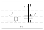
도 1은 종래 과적 단속 시스템을 도시한 도면이다. 1 is a view showing a conventional overload control system.
도 1을 참조하면, 검문소에서의 과적단속 시스템은 고속 축중기와 저속 축중기 시스템을 이용하는 방안으로서, 화물차량이 도로로 통행하는 지점에 고속 축중기 시스템을 설치하여 차량의 중량을 검측한다. Referring to FIG. 1, the overload control system at a checkpoint is a method of using a high-speed and low-speed accumulator system, and the weight of a vehicle is detected by installing a high-speed accumulator system at a point where a freight vehicle passes on the road.
고속 축중기(High Speed WIM, HS-WIM) 시스템은 저속 축중기(Low Speed WIM, LS-WIM) 시스템보다 정확도가 떨어지지만 고속으로 주행하는 화물차량의 중량을 측정할 수 있는 장점을 가지고 있다. 따라서 고속 축중기를 통해 1차 과적 의심 화물차량을 검측해내고, 검측된 1차 과적 의심 차량을 저속 축중기 시스템에서 2차로 검측하는 방식이다. 이는 교통흐름을 유지하면서 과적단속을 할 수 있는 효과적인 방식으로 세계의 많은 국가에서 유사한 방식으로 과적단속을 진행하고 있다. 이에 대한 구체적인 과적 단속 절차는 다음과 같다.High Speed WIM (HS-WIM) systems are less accurate than Low Speed WIM (LS-WIM) systems, but have the advantage of being able to measure the weight of a freight vehicle traveling at high speed. Therefore, it is a method of detecting the primary overloaded suspicious vehicle through the high-speed accumulator and secondly detecting the detected suspected overload vehicle in the low-speed accumulator system. This is an effective way to overload control while maintaining traffic flow, and many countries around the world carry out overload control in a similar way. The specific oversight procedure is as follows.
① 고속 축중기 시스템에서 화물차량을 검측 후 과적이 발생하면, 사무실에 “혐의차량발생” 알람을 울리고, 사무실에서는 초소 근무자에게 과적차량이 진입함을 벨로 알리고, 초소에 과적차량의 번호판을 알려준다. ① If an overload occurs after inspecting a freight vehicle in a high-speed loader system, an alarm is issued to the office, and the office notifies the guard worker that the overload vehicle is entering, and informs the guard of the overload vehicle license plate.
② 고속 축중기 시스템은 초소 전방에 있으므로 초소 근무자는 초소밖으로 나와 깃발을 통해 과적차량을 저속 축중기로 유도하게 된다. 이때, 이 동영상을 도주차량 단속시스템의 CCTV가 녹화하게 된다. ② Since the high-speed crane system is located in front of the guard post, the guard workers will come out of the guard post and lead the overload vehicle to the low-speed crane through the flag. At this time, CCTV of the escape control system will record this video.
③ 저속으로 진입한 차량은 2차 재검측을 하여 과적으로 판명되면 자인서를 작성하고 고발된다. ③ Vehicles that enter at low speeds are subject to a second re-inspection, and if they are found to be excessive, a self-signed letter will be prepared and accused.
④ 만약 초소 근무자의 유도를 거부하고 도주하게 되면, 도주차량 단속시스템의 번호인식 제어기를 통해 도주차량을 적발하고, ②번의 CCTV 녹화영상과 함께 도주 사실에 대한 고발이 이루어진다. ④ If he or she refuses to induce induction, the escape vehicle is caught through the number recognition controller of the escape vehicle enforcement system, and a complaint of escape is made with the CCTV recorded
이러한 과적 단속 시스템의 경우, 차로에 센서를 설치하여 센서를 통과하는 윤중량을 검측하는 방식으로 차량의 하중을 측정한다. 즉, 좌우 윤중의 합이 축중이며, 차량의 모든 축의 합하여 총 중량을 계산하는 것이다. 국내 도로법 기준으로 총 중량 40톤 초과, 축 중량 10톤 초과이면 과적차량으로 고발된다. In the case of such an overload control system, a sensor is installed in a lane to measure the load of the vehicle by detecting the wheel weight passing through the sensor. In other words, the sum of the left and right wheel weights is on the shaft, and the total weight is calculated by adding up all the shafts of the vehicle. If the total weight exceeds 40 tons and the shaft weight exceeds 10 tons according to the National Road Act, it will be prosecuted as an overload vehicle.
도 1에서 보는 바와 같이, 과적 단속 시스템은 각 차로에 중량을 감지하는 센서(1)를 설치하고 있으며, 이를 통해 각 차로를 통과하는 차량의 축 중량을 검지한다. As shown in FIG. 1, the overload control system is equipped with a
그러나, 종래 과적 단속 시스템에서는 센서(1)를 회피하여 주행하는 비정상 주행을 하는 차량에 대하여 정확한 계중을 하지 못하여, 과적 단속이 제대로 이루어지지 못하는 문제점이 있다. 종래 과적 단속 시스템에서 과적 단속을 회피하기 위한, 이른바 회피 주행을 하는 예를 설명하면 다음과 같다. However, in the conventional overload control system, there is a problem in that the overload control is not properly performed because the
도 2는 3차로 도로에서 비정상 주행의 예이다. 2 is an example of an abnormal driving on a road with three lanes.
도 2를 참조하면, 3차선 도로에 센서(1)가 설치되어 있는데, 화물 차량이 차로의 중앙으로 통과하지 않고, 차선을 밟고 지나가는 방식으로 비정상 주행을 하는 예이다. 이러한 예를 포함하여 종래 차량이 차로를 벗어나서 주행하는 회피주행의 경우를 살펴보면 다음과 같다. Referring to FIG. 2, a
1) 측대주행: 중앙분리대 측의 도로와 1차로를 걸쳐주행하는 경우로서, 측대쪽에 센서가 없어 차량의 중량이 감소하게 된다. 1) Side-to-side driving: As a case of driving across the road and primary lane on the side of the median, the weight of the vehicle is reduced because there is no sensor on the side.
2) 양차로주행: 1-2차로에 걸쳐 주행하거나, 2-3차로에 걸쳐 주행하는 등과 같이 2개 차로를 걸쳐 주행하는 경우이다. 이 경우, 차로 단위로 단위차량을 분리하기 때문에 정확한 중량 계산이 불가능하게 된다. 2) Driving on two lanes: Two or two lanes, such as two or two lanes. In this case, since the unit vehicle is separated into units by lane, accurate weight calculation becomes impossible.
3) 길어깨주행: 일반적으로 갓길로 운행하는 주행이다. 갓길은 도로의 폭이 일정하지 않고 포장재질이 약하여 중량센서를 설치하지 않으므로, 차량 중량 측정이 불가능하다. 3) Driving on the shoulders: Generally, it is a road-driven driving. Because the road width is not constant and the pavement material is weak, the weight sensor is not installed, so it is impossible to measure the vehicle weight.
4) 가감속주행: 차량이 센서구간에서 속도를 급격히 변화시켜 중량을 감소시키는 주행행위이다. 보통 중량을 측정하는 센서의 넓이가 좁기 때문에 센서 설치영역에서 급 가감속을 할 경우, 관성의 법칙에 의해 차량의 중량이 축에서 축으로 이동하는 효과가 발생하고, 이를 이용하여 적재중량을 속이는 방법이다. 4) Acceleration / deceleration driving: This is a driving action in which the vehicle reduces the weight by rapidly changing the speed in the sensor section. Normally, the width of the sensor that measures the weight is narrow, so when the acceleration / deceleration in the sensor installation area occurs, the effect of the vehicle's weight moving from axis to axis occurs by the law of inertia. to be.
5) 차선밟기: 차선을 밟고 주행하는 행위이다. 차선을 밟고 지나갈 경우, 센서의 끝부분을 걸쳐 밟기 때문에 윤중량이 적어지는 효과가 있으며, 실제로 운전자들이 가장 많이 사용하는 위법행위이다. 5) Stepping on the lane: This is the act of driving on the lane. When you step on a lane, it is effective in reducing the weight of the wheel because it is stepped over the end of the sensor, and it is actually the most illegal act used by drivers.
이러한 회피 주행이 많아질 경우, 과적 단속 시스템이 무력화되어 단속 행위가 불가능해지는 문제가 발생하게 된다.When such avoidance driving increases, a problem arises in that the overload control system becomes incapacitated, making it impossible to perform the enforcement action.
예를 들어, 전술한 차선밟기 주행 차량의 경우에는 센서의 길이를 넓게 변경해도, 회피 주행 차량을 적발하기가 어렵다는 문제가 있다. For example, in the case of the lane-driving vehicle described above, there is a problem in that it is difficult to detect an evasive traveling vehicle even if the length of the sensor is changed widely.
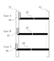
도 3은 회피 주행 중 차선 밟기 비정상 주행을 도시한 도면이다. 3 is a view showing abnormal driving on the lane during avoidance driving.
도 3을 참조하면, 차선 밝기 비정상 주행의 세가지 경우(Case A, Case B, Case C)가 도시되어 있는데, 중량 센서(30)의 길이를 조절하여 해결하는 것이 불가능하다는 것을 확인할 수 있다. 즉, 중량 센서(30)를 차선(70) 내부 끝선에 맞추는 경우(Case A), 또는 중량 센서(30)의 길이를 길게 하여 차선(70)을 모두 덮어서 맞추는 경우(Case C) 등 차량의 타이어(40)가 중량 센서(40)의 일 부분만을 밟고 지나가게 되면, 모두 비정상주행으로 인한 미검지 문제를 야기하게 된다. Referring to FIG. 3, three cases (Case A, Case B, and Case C) of abnormal driving of the lane brightness are illustrated, and it can be confirmed that it is impossible to solve by adjusting the length of the
본 발명은 상기와 같은 문제점을 해결하기 위하여 안출된 것으로서, 과적 단속 시스템에서 과적 단속을 피하기 위해 중량 센서를 회피하여 주행하는 차량을 검지하는 장치를 제공하는데 그 목적이 있다.The present invention has been devised to solve the above problems, and an object thereof is to provide an apparatus for detecting a vehicle traveling by avoiding a weight sensor in order to avoid an excessive interruption in an excessive enforcement system.
본 발명의 목적은 이상에서 언급한 목적으로 제한되지 않으며, 언급되지 않은 또 다른 목적들은 아래의 기재로부터 통상의 기술자에게 명확하게 이해될 수 있을 것이다.The objects of the present invention are not limited to the above-mentioned objects, and other objects not mentioned will be clearly understood by those skilled in the art from the following description.
이와 같은 목적을 달성하기 위한 본 발명의 과적 단속 시스템에서의 회피 차량 검지 장치에서, 각 차로마다 설치되어, 차량의 중량을 감지하기 위한 제1 중량감지센서, 각 차로마다 설치되어, 차량의 중량을 감지하기 위한 제2 중량감지센서, 각 차로마다 설치되어, 통행하는 차량을 감지하기 위한 루프센서, 각 차로마다 설치되어, 상기 제1 중량감지센서 및 상기 제2 중량감지센서를 피하기 위해 차로를 벗어나서 주행하는 차량인 회피 차량을 감지하기 위한 회피주행 감지센서 및 상기 제1 중량감지센서, 상기 제2 중량감지센서, 상기 루프센서, 상기 회피주행 감지센서로부터 감지된 신호를 이용하여 각 차로를 통행하는 차량 중에서 회피 차량을 판별하는 제어부를 포함한다.In the avoidance vehicle detection device in the overload control system of the present invention for achieving the above object, it is installed in each lane, the first weight sensor for detecting the weight of the vehicle, installed in each lane, the weight of the vehicle A second weight sensor for sensing, installed in each lane, a loop sensor for detecting a passing vehicle, installed in each lane, out of the lane to avoid the first weight sensor and the second weight sensor A vehicle that travels through each lane using signals detected from the avoidance driving detection sensor, the first weight detection sensor, the second weight detection sensor, the loop sensor, and the avoidance driving detection sensor for detecting a avoidance vehicle that is a driving vehicle. And a control unit for determining an evasive vehicle among vehicles.
본 발명에서, 각 차로에서 차량의 주행 방향을 기준으로, 상기 제1 중량감지센서, 상기 루프센서, 상기 제2 중량감지센서 및 상기 회피주행 감지센서의 순서로 위치한다. In the present invention, based on the driving direction of the vehicle in each lane, the first weight sensor, the loop sensor, the second weight sensor and located in the order of the avoidance driving sensor.
그리고, 본 발명의 일 실시예에서 상기 회피주행 감지센서는 각 차로에 비스듬히 사선 방향으로 설치될 수 있다. In addition, in one embodiment of the present invention, the avoidance driving detection sensor may be installed at an oblique diagonal direction to each lane.
또는, 본 발명의 다른 실시예에서 상기 회피주행 감지센서는 각 차로마다 두 개씩 설치되되, 각 차로의 폭을 양분하는 가상의 중심선을 기준으로, 양쪽에 비스듬히 사선 방향으로 두 개씩 설치될 수 있다. Alternatively, in another embodiment of the present invention, the avoidance driving detection sensors are provided two for each lane, and may be installed two at an oblique diagonal direction on both sides, based on a virtual center line dividing the width of each lane.
상기 제어부는 상기 회피주행 감지센서에서 감지된 신호를 이용하여 차량의 윤폭과 차로 내 차량의 위치를 산출하고, 산출된 윤폭과 위치를 통해 해당 차량이 상기 제1 중량감지센서 및 상기 제2 중량감지센서를 회피하는 주행을 하였는지 여부를 판단할 수 있다. The control unit calculates the wheel width of the vehicle and the position of the vehicle in the lane using the signal detected by the avoidance driving sensor, and the vehicle detects the first weight sensor and the second weight through the calculated wheel width and position. It can be determined whether or not the vehicle has been driven to avoid the sensor.
본 발명에 의하면, 과적 단속 시스템에서 중량 센서를 회피하여 통과하기 위한 회피 차량을 검지함으로써, 정확한 중량 계측을 통해 과적 단속 업무의 효율성을 향상시킬 수 있는 효과가 있다. According to the present invention, it is possible to improve the efficiency of the task of overload control through accurate weight measurement by detecting the evacuation vehicle for evading and passing the weight sensor in the overload control system.
도 1은 종래 과적 단속 시스템을 도시한 도면이다.
도 2는 3차로 도로에서 비정상 주행의 예이다.
도 3은 회피 주행 중 차선 밟기 비정상 주행을 도시한 도면이다.
도 4는 본 발명의 일 실시예에 따른 과적 단속 시스템에서 회피 차량 검지 장치의 내부 구성을 보여주는 블록도이다.
도 5는 본 발명의 일 실시예에 따른 회피 차량 검지 장치에서 센서들의 레이아웃(layout)을 도시한 것이다.
도 6은 본 발명의 일 실시예에 따른 중량감지센서에서 감지된 신호 파형을 도시한 것이다.
도 7은 본 발명의 일 실시예에 따른 회피차량 감지센서에서 감지된 신호 파형을 도시한 것이다.
도 8은 본 발명의 일 실시예에 따른 차로 내 차량의 위치를 검측하는 방식을 설명하기 위한 도면이다.
도 9는 본 발명의 다른 실시예에 따른 회피 차량 검지 장치에서 센서들의 레이아웃을 도시한 것이다.
도 10은 본 발명의 다른 실시예에 따른 회피 차량 검지 장치에서 비정상 주행의 경우를 예시한 것이다. 1 is a view showing a conventional overload control system.
2 is an example of an abnormal driving on a road with three lanes.
3 is a view showing abnormal driving on the lane during avoidance driving.
4 is a block diagram showing an internal configuration of an evasion vehicle detection device in an overload control system according to an embodiment of the present invention.
5 illustrates a layout of sensors in an evasive vehicle detection device according to an embodiment of the present invention.
6 shows a signal waveform detected by the weight sensor according to an embodiment of the present invention.
7 illustrates a signal waveform detected by the avoidance vehicle detection sensor according to an embodiment of the present invention.
8 is a view for explaining a method of detecting the position of a vehicle in a lane according to an embodiment of the present invention.
9 illustrates the layout of the sensors in the evasive vehicle detection device according to another embodiment of the present invention.
10 illustrates a case of abnormal driving in an evasive vehicle detection device according to another embodiment of the present invention.
본 발명은 다양한 변경을 가할 수 있고 여러 가지 실시예를 가질 수 있는 바, 특정 실시예들을 도면에 예시하고 상세하게 설명하고자 한다. 그러나, 이는 본 발명을 특정한 실시 형태에 대해 한정하려는 것이 아니며, 본 발명의 사상 및 기술 범위에 포함되는 모든 변경, 균등물 내지 대체물을 포함하는 것으로 이해되어야 한다.The present invention can be applied to various changes and can have various embodiments, and specific embodiments will be illustrated in the drawings and described in detail. However, this is not intended to limit the present invention to specific embodiments, and should be understood to include all modifications, equivalents, and substitutes included in the spirit and scope of the present invention.
본 출원에서 사용한 용어는 단지 특정한 실시예를 설명하기 위해 사용된 것으로, 본 발명을 한정하려는 의도가 아니다. 단수의 표현은 문맥상 명백하게 다르게 뜻하지 않는 한, 복수의 표현을 포함한다. 본 출원에서, "포함하다" 또는 "가지다" 등의 용어는 명세서 상에 기재된 특징, 숫자, 단계, 동작, 구성요소, 부품 또는 이들을 조합한 것이 존재함을 지정하려는 것이지, 하나 또는 그 이상의 다른 특징들이나 숫자, 단계, 동작, 구성요소, 부품 또는 이들을 조합한 것들의 존재 또는 부가 가능성을 미리 배제하지 않는 것으로 이해되어야 한다.The terms used in this application are only used to describe specific embodiments, and are not intended to limit the present invention. Singular expressions include plural expressions unless the context clearly indicates otherwise. In this application, terms such as “include” or “have” are intended to indicate that a feature, number, step, operation, component, part, or combination thereof described on the specification exists, and that one or more other features are present. It should be understood that the existence or addition possibilities of fields or numbers, steps, operations, components, parts or combinations thereof are not excluded in advance.
다르게 정의되지 않는 한, 기술적이거나 과학적인 용어를 포함해서 여기서 사용되는 모든 용어들은 본 발명이 속하는 기술 분야에서 통상의 지식을 가진 자에 의해 일반적으로 이해되는 것과 동일한 의미를 갖고 있다. 일반적으로 사용되는 사전에 정의되어 있는 것과 같은 용어들은 관련 기술의 문맥 상 갖는 의미와 일치하는 의미를 갖는 것으로 해석되어야 하며, 본 출원에서 명백하게 정의하지 않는 한, 이상적이거나 과도하게 형식적인 의미로 해석되지 않는다.Unless defined otherwise, all terms used herein, including technical or scientific terms, have the same meaning as commonly understood by a person skilled in the art to which the present invention pertains. Terms, such as those defined in a commonly used dictionary, should be interpreted as having meanings consistent with meanings in the context of related technologies, and should not be interpreted as ideal or excessively formal meanings unless explicitly defined in the present application. Does not.
또한, 첨부 도면을 참조하여 설명함에 있어, 도면 부호에 관계없이 동일한 구성 요소는 동일한 참조 부호를 부여하고 이에 대한 중복되는 설명은 생략하기로 한다. 본 발명을 설명함에 있어서 관련된 공지 기술에 대한 구체적인 설명이 본 발명의 요지를 불필요하게 흐릴 수 있다고 판단되는 경우 그 상세한 설명을 생략한다.In addition, in the description with reference to the accompanying drawings, the same components are given the same reference numerals regardless of the reference numerals, and redundant descriptions thereof will be omitted. In the description of the present invention, when it is determined that detailed descriptions of related known technologies may unnecessarily obscure the subject matter of the present invention, detailed descriptions thereof will be omitted.
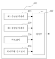
도 4는 본 발명의 일 실시예에 따른 과적 단속 시스템에서 회피 차량 검지 장치의 내부 구성을 보여주는 블록도이고, 도 5는 본 발명의 일 실시예에 따른 회피 차량 검지 장치에서 센서들의 레이아웃(layout)을 도시한 것이다. 4 is a block diagram showing the internal configuration of an evasion vehicle detection device in an overload control system according to an embodiment of the present invention, and FIG. 5 is a layout of sensors in an evasion vehicle detection device according to an embodiment of the present invention It is shown.
도 4 및 도 5를 참조하면, 본 발명의 과적 단속 시스템에서의 회피 차량 검지 장치(400)는 제1 중량감지센서(210), 제2 중량감지센서(220), 루프센서(300), 회피주행 감지센서(100), 제어부(410)를 포함한다. 4 and 5, the avoidance
제1 중량감지센서(210)는 각 차로마다 설치되어, 차량의 중량을 감지하는 역할을 한다. The
제2 중량감지센서(220)는 각 차로마다 설치되어, 차량의 중량을 감지하는 역할을 한다. The
루프센서(loop sensor)(300)는 각 차로마다 설치되어, 통행하는 차량을 감지하는 역할을 한다. A
회피주행 감지센서(100)는 각 차로마다 설치되어, 제1 중량감지센서(210) 및 제2 중량감지센서(220)를 피하기 위해 차로를 벗어나서 주행하는 차량인 회피 차량을 감지하는 역할을 한다. The avoidance driving
제어부(410)는 제1 중량감지센서(210), 제2 중량감지센서(220), 루프센서(300), 회피주행 감지센서(100)로부터 감지된 신호를 이용하여 각 차로를 통행하는 차량 중에서 회피 차량을 판별한다. The
도 5에서 보는 바와 같이, 본 발명에서 각 차로에서 차량의 주행 방향을 기준으로, 제1 중량감지센서(210), 루프센서(300), 제2 중량감지센서(220) 및 회피주행 감지센서(100)의 순서로 위치되는 것이 바람직하다.As shown in Figure 5, based on the driving direction of the vehicle in each lane in the present invention, the
그리고, 회피주행 감지센서(100)는 각 차로에 비스듬히 사선 방향으로 설치될 수 있다. 본 발명에서 회피주행 감지센서(100)는 검측신호를 전기신호로 변환할 수 있는 다양한 전기신호 센서들이 사용될 수 있으며, 예를 들어 피에조 센서로 구현될 수 있다. In addition, the avoidance driving
제1 중량감지센서(210) 및 제2 중량감지센서(220)는 각 차로마다 좌측 윤과 우측 윤을 각각 측정할 수 있는 길이로 설치될 수 있다. The first
제어부(410)는 회피주행 감지센서(100)에서 감지된 신호를 이용하여 차량의 윤폭과 차로 내 차량의 위치를 산출하고, 산출된 윤폭과 위치를 통해 해당 차량이 제1 중량감지센서(210) 및 제2 중량감지센서(220)를 회피하는 주행을 하였는지 여부를 판단한다. The
본 발명에서는 도 5에서 보는 바와 같은 레이아웃의 센서를 배치하여 회피주행 차량을 검지할 수 있다. 이에 대해 구체적인 내용을 설명하면 다음과 같다. In the present invention, a sensor having a layout as shown in FIG. 5 can be arranged to detect an evasive vehicle. The details are as follows.
1) 측대주행: 측대쪽을 통과하는 윤중값이 0이고, 1차로를 통과하는 윤중이 정상값이므로, 좌측 윤중값이 0이고, 우측 윤중값이 정상값이라는 결과를 통해 비정상주행을 검지할 수 있다. 1) Side-to-side driving: Since the wheel weight passing through the side-side is 0, and the wheel weight passing through the primary lane is a normal value, the left wheel weight value is 0 and the right wheel weight value is a normal value. have.
2) 양차로주행: 두 개의 차로가 각각 차량의 중량을 검지하며, 각 차로의 결과에서 좌우 윤중이 0인 값을 갖는 경우 양차로 주행으로 판단한다. 여기서, 1차로의 경우 측대주행과 양차로주행의 결과가 동일한데, 이 경우 좌측과 우측의 윤중을 확인하여 측대주행인지 양차로주행인지를 판단한다. 2) Driving on two lanes: Two lanes detect the weight of each vehicle, and if the left and right wheel weights have a value of 0 in the results of each lane, it is judged as driving on both lanes. Here, in the case of the first lane, the results of the side-to-side driving and the two-way driving are the same. In this case, it is determined whether the side-to-side driving or the two-way driving by checking the left and right wheel centers.
3) 갓길주행: 중량이 검지되지 않고, 별도로 설치된 갓길센서의 루프트리거 신호를 통해 갓길주행 차량을 검지할 수 있다. 3) Shoulder driving: The weight is not detected, and the driving vehicle can be detected through the roof trigger signal of the separately installed shoulder sensor.
4) 가감속주행: 센서 간의 순간 속도를 계산하여 가감속주행 차량을 검지할 수 있다. 예를 들어, 제1 중량감지센서(210)와 루프센서(300) 간 속도, 루프센서(300)와 제2 중량감지센서(220) 간 속도, 제2 중량감지센서(220)와 회피주행 감지센서(100) 간 속도를 계산하고, 이에 대한 속도변화를 확인하여 가감속주행 차량을 검지할 수 있다. 4) Acceleration / deceleration driving: Acceleration / deceleration driving vehicles can be detected by calculating the instantaneous speed between sensors. For example, the speed between the
5) 차선 밟기 주행: 차량의 타이어가 센서를 부분적으로 밟고 지나가는 차선 밝기 주행의 경우, 이에 대한 검지 과정은 다음과 같다. 5) Stepping on the lane: In the case of lane brightness driving in which the tire of the vehicle partially passes on the sensor, the detection process is as follows.
본 발명에서 회피주행 감지센서(100)는 차로에 설치되어 차량이 주행할 경우차량이 차로내에서 주행하는 방향을 알 수 있으며, 또한 신호파형을 통해 차량의 윤폭을 계산할 수 있다.In the present invention, the avoidance driving
도 6은 본 발명의 일 실시예에 따른 중량감지센서에서 감지된 신호 파형을 도시한 것이다. 6 shows a signal waveform detected by the weight sensor according to an embodiment of the present invention.
도 6을 참조하면, 중량감지센서(210), 220)에서 차량의 축이 통과하면서 이에 대한 중량을 감지하는 것이 신호 파형으로 나타나 있다. Referring to FIG. 6, the
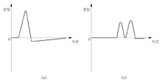
도 7은 본 발명의 일 실시예에 따른 회피차량 감지센서에서 감지된 신호 파형을 도시한 것이다. 도 7에서 (a)는 싱글타이어가 구비된 차량의 경우이고, (b)는 듀얼타이어가 구비된 차량의 경우이다. 7 illustrates a signal waveform detected by the avoidance vehicle detection sensor according to an embodiment of the present invention. In FIG. 7, (a) is for a vehicle equipped with a single tire, and (b) is for a vehicle equipped with a dual tire.
도 7을 참조하면, 회피차량 감지센서(100)에 타이어가 최초로 접촉한 시점부터 신호파형이 시작되고, 타이어가 벗어난 시점에 신호파형이 종료된다. 즉, 신호파형은 타이어가 회피차량 감지센서(100)에 접촉한 시점부터 벗어난 시점가지를 나타낸다. 이러한 신호 파형의 상승하는 시작점과 끝점간의 간격을 통해 차량의 윤폭을 계산할 수 있다. Referring to FIG. 7, the signal waveform starts from the time the tire first contacts the avoidance
도 8은 본 발명의 일 실시예에 따른 차로 내 차량의 위치를 검측하는 방식을 설명하기 위한 도면이다. 8 is a view for explaining a method of detecting the position of a vehicle in a lane according to an embodiment of the present invention.
도 8을 참조하면, 차량이 제2 중량감지센서(220)와 회피주행 감지센서(100)를 통과한 경우이다. 여기서, 차로에 센서 설치시, 제2 중량감지센서(220)와 회피주행 감지센서(100)가 이루는 각도(θ)와, 제2 중량감지센서(220)의 길이 및 차로 내 위치 정보는 미리 설정되어 있다고 가정한다. Referring to FIG. 8, the vehicle passes through the
전술한 바와 같이, 차량이 제2 중량감지센서(220)를 통과할 때의 속도(V)를 계산할 수 있다. As described above, the speed V when the vehicle passes through the
그리고, 차량이 제2 중량감지센서(220)를 통과한 시간을 Wt라 하고, 차량이 회피주행 감지센서(100)를 통과한 시간을 Pt라 하면, 차량이 제2 중량감지센서(220)와 회피주행 감지센서(100)를 통과한 시간을 Lt=Pt-Wt로 나타낼 수 있다. In addition, when the time when the vehicle passes through the
그러면, 차량이 제2 중량감지센서(220)와 회피주행 감지센서(100)를 통과한 거리 S=V×Lt로 계산할 수 있다.Then, the vehicle may be calculated as the distance S = V × Lt that passes through the
도 8에서, 차량이 통과한 통과 지점(710)을 알고 있으므로, 전술한 정보를 통해 θ를 하나의 각으로 하는 삼각형을 구할 수 있고, 이 삼각형에서 제2 중량감지센서(220)와 회피주행 감지센서(100) 사이의 거리(S)를 이미 계산하여 알고 있다. 여기서, 중량감지센서(220)와 회피주행 감지센서(100) 사이의 거리(S)를 Lheight라 하면, 삼각함수의 탄젠트(tangent) 정보를 이용하여 제2 중량감지센서(220) 상의 길이 Ltarget을 다음과 같이 구할 수 있다. In FIG. 8, since the
[수학식 1][Equation 1]
Tan(θ)= Lheight / Ltarget Tan (θ) = L height / L target
Ltarget = Lheight×Tan(θ)L target = L height × Tan (θ)
여기서, SS와 통과 지점(710) 간의 거리이다. Here, it is the distance between the SS and the
이상의 방식을 통해, 차로를 통행하는 차량의 위치정보와 윤폭을 계산할 수 있다. 그리고, 차량이 차선을 밟고 주행하는 회피 주행을 하는 경우, 차선으로부터의 위치정보와 윤폭을 계산하여, 중량감지센서(210, 220)를 정확히 밟고 지나갔는지 여부를 판단할 수 있다. Through the above method, it is possible to calculate the location information and the wheel width of the vehicle passing through the lane. In addition, when the vehicle is in an evasive driving stepped on the lane, it is possible to determine whether the
도 9는 본 발명의 다른 실시예에 따른 회피 차량 검지 장치에서 센서들의 레이아웃을 도시한 것이다. 9 illustrates the layout of the sensors in the evasive vehicle detection device according to another embodiment of the present invention.
도 9의 실시예는 도 5의 제1 실시예에서 회피주행 감지센서의 형태를 변경한 제2 실시예이다. 9 is a second embodiment in which the form of the avoidance driving detection sensor is changed in the first embodiment of FIG. 5.
도 9를 참조하면, 본 발명의 제2 실시예에서 회피주행 감지센서(101, 102)는 각 차로마다 두 개씩 설치되되, 각 차로의 폭을 양분하는 가상의 중심선을 기준으로, 양쪽에 비스듬히 사선 방향으로 두 개씩 설치될 수 있다. Referring to FIG. 9, in the second embodiment of the present invention, two avoidance driving
이렇게 본 발명에서는 다른 실시예를 통해 두 개의 회피주행 감지센서(101, 102)로부터 좌측 윤폭과 우측 윤폭을 각각 구할 수 있으며, 이를 응용하여 다음과 같은 경우의 비정상 주행 행태를 검지할 수 있다. In this way, in the present invention, the left wheel width and the right wheel width are respectively obtained from the two avoidance driving
도 10은 본 발명의 다른 실시예에 따른 회피 차량 검지 장치에서 비정상 주행의 경우를 예시한 것이다. 10 illustrates a case of abnormal driving in an evasive vehicle detection device according to another embodiment of the present invention.
도 10을 참조하면, 제1 회피주행 감지센서(101)에서 검측된 윤폭과 제2 회피주행 감지센서(102)에서 검측된 윤폭을 비교하여, 정상주행과 비정상주행을 판단할 수 있다. 즉, 제1 회피주행 감지센서(101)에서 검측된 윤폭과 제2 회피주행 감지센서(102)에서 검측된 윤폭을 비교하여, 도 10과 같이 윤폭이 동일하지 않으면, 차선(70)을 밟고 주행하는 등, 중량감지센서를 제대로 통과하지 않고, 회피 주행을 한 것으로 판단하여, 회피 차량을 검지할 수 있다. Referring to FIG. 10, it is possible to determine normal driving and abnormal driving by comparing the leap width detected by the first avoided driving
과적 단속 시스템에서 단속 데이터의 신뢰성을 검증할 수 없는 예외 상황은 시스템 전체의 성능 및 기능을 무효화 할 수 있는 치명적인 단점이 될 수 있다. 이처럼, 과적 단속 시스템에서 중량 정보에 대한 신뢰성 부분은 어떠한 기능보다 중요하며, 이를 명확히 검증하지 못한다면 운전자와의 대면 단속 시 기술적인 마찰을 피할 수 없게 된다. An exception situation in which the reliability of the intermittent data cannot be verified in an excessive intermittent system can be a fatal disadvantage that may invalidate the overall performance and function of the system. In this way, the reliability of the weight information is more important than any function in the overload control system. If it is not clearly verified, technical friction cannot be avoided in the face-to-face control with the driver.
본 발명은 이러한 기존의 과적 단속 시스템이 가지고 있는 치명적인 약점이며, 가장 많이 발생하는 회피주행 중 하나인 차선 밟기에 대해 정확한 검지가 가능함으로써, 과적 단속 장비의 중량 검지 예외 상황을 제거하였고, 이를 통해 과적 단속 업무의 효율성을 향상시킬 수 있다.The present invention is a fatal weakness of the existing overload control system, and it is possible to accurately detect the stepping on the lane, which is one of the most frequent avoidance driving, thereby removing the weight detection exception of the overload control equipment, and through this, the overload Enhance the effectiveness of crackdown work.
이상 본 발명을 몇 가지 바람직한 실시예를 사용하여 설명하였으나, 이들 실시예는 예시적인 것이며 한정적인 것이 아니다. 본 발명이 속하는 기술분야에서 통상의 지식을 지닌 자라면 본 발명의 사상과 첨부된 특허청구범위에 제시된 권리범위에서 벗어나지 않으면서 다양한 변화와 수정을 가할 수 있음을 이해할 것이다.Although the present invention has been described using several preferred embodiments, these embodiments are illustrative and not limiting. Those skilled in the art to which the present invention pertains will understand that various changes and modifications can be made without departing from the spirit of the present invention and the scope of the rights set forth in the appended claims.
100 회피주행 감지센서
210 제1 중량감지센서
220 제2 중량감지센서
300 루프센서
410 제어부
400 회피 차량 검지 장치100 Evasion driving
220
410
Claims (4)
각 차로마다 설치되어, 차량의 중량을 감지하기 위한 제1 중량감지센서;
각 차로마다 설치되어, 차량의 중량을 감지하기 위한 제2 중량감지센서;
각 차로마다 설치되어, 통행하는 차량을 감지하기 위한 루프센서;
각 차로마다 설치되어, 상기 제1 중량감지센서 및 상기 제2 중량감지센서를 피하기 위해 차로를 벗어나서 주행하는 차량인 회피 차량을 감지하기 위한 회피주행 감지센서; 및
상기 제1 중량감지센서, 상기 제2 중량감지센서, 상기 루프센서, 상기 회피주행 감지센서로부터 감지된 신호를 이용하여 각 차로를 통행하는 차량 중에서 회피 차량을 판별하는 제어부를 포함하며,
각 차로에서 차량의 주행 방향을 기준으로, 상기 제1 중량감지센서, 상기 루프센서, 상기 제2 중량감지센서 및 상기 회피주행 감지센서의 순서로 위치되는 것을 특징으로 하는 회피 차량 검지 장치.
In the avoidance vehicle detection device in the overload control system,
A first weight detection sensor installed in each lane to detect the weight of the vehicle;
A second weight detection sensor installed in each lane to detect the weight of the vehicle;
It is installed in each lane, a loop sensor for detecting a passing vehicle;
An avoidance driving detection sensor installed in each lane to detect an evasive vehicle that is a vehicle traveling out of the lane to avoid the first weight sensor and the second weight sensor; And
It includes a control unit for determining the avoided vehicle among vehicles passing through each lane using the signals detected from the first weight sensor, the second weight sensor, the loop sensor, and the avoidance driving sensor,
Evacuation vehicle detection device, characterized in that located in the order of the first weight sensor, the loop sensor, the second weight sensor and the avoidance driving detection sensor, based on the driving direction of the vehicle in each lane.
상기 회피주행 감지센서는 각 차로에 비스듬히 사선 방향으로 설치되는 것을 특징으로 하는 회피 차량 검지 장치
The method according to claim 1,
The avoidance driving detection sensor is an evasion vehicle detection device, characterized in that installed in an oblique diagonal direction to each lane
상기 회피주행 감지센서는 각 차로마다 두 개씩 설치되되, 각 차로의 폭을 양분하는 가상의 중심선을 기준으로, 양쪽에 비스듬히 사선 방향으로 두 개씩 설치되는 것을 특징으로 하는 회피 차량 검지 장치
The method according to claim 1,
Two avoidance driving detection sensors are installed for each lane, and two avoidance vehicle detection devices are installed on both sides in an oblique diagonal direction based on a virtual center line dividing the width of each lane.
상기 제어부는 상기 회피주행 감지센서에서 감지된 신호를 이용하여 차량의 윤폭과 차로 내 차량의 위치를 산출하고, 산출된 윤폭과 위치를 통해 해당 차량이 상기 제1 중량감지센서 및 상기 제2 중량감지센서를 회피하는 주행을 하였는지 여부를 판단하는 것을 특징으로 하는 회피 차량 검지 장치.
The method according to claim 2 or claim 3,
The control unit calculates the wheel width of the vehicle and the position of the vehicle in the lane using the signal detected by the avoidance driving detection sensor, and the vehicle detects the first weight sensor and the second weight through the calculated wheel width and location. An evasion vehicle detection device, characterized in that it is determined whether or not the vehicle is evading the sensor.
Priority Applications (1)
| Application Number | Priority Date | Filing Date | Title |
|---|---|---|---|
| KR1020180124910A KR20200044331A (en) | 2018-10-19 | 2018-10-19 | Apparatus for detecting avoidance vehicle in controlling overloaded vehicle system |
Applications Claiming Priority (1)
| Application Number | Priority Date | Filing Date | Title |
|---|---|---|---|
| KR1020180124910A KR20200044331A (en) | 2018-10-19 | 2018-10-19 | Apparatus for detecting avoidance vehicle in controlling overloaded vehicle system |
Publications (1)
| Publication Number | Publication Date |
|---|---|
| KR20200044331A true KR20200044331A (en) | 2020-04-29 |
Family
ID=70466528
Family Applications (1)
| Application Number | Title | Priority Date | Filing Date |
|---|---|---|---|
| KR1020180124910A Ceased KR20200044331A (en) | 2018-10-19 | 2018-10-19 | Apparatus for detecting avoidance vehicle in controlling overloaded vehicle system |
Country Status (1)
| Country | Link |
|---|---|
| KR (1) | KR20200044331A (en) |
Cited By (2)
| Publication number | Priority date | Publication date | Assignee | Title |
|---|---|---|---|---|
| KR102414212B1 (en) * | 2021-03-09 | 2022-06-28 | 김학선 | Truck scale and vehicle weight measurement monitoring system |
| KR102652609B1 (en) * | 2023-12-20 | 2024-04-01 | 한국건설기술연구원 | Apparatus and Method for Providing Speed Profile of Heavy Vehicle Suspected of being Overloaded |
Citations (1)
| Publication number | Priority date | Publication date | Assignee | Title |
|---|---|---|---|---|
| KR101115589B1 (en) | 2011-08-24 | 2012-03-05 | 한국도로전산 주식회사 | Apparatus and method for measuring weight of vehicle |
-
2018
- 2018-10-19 KR KR1020180124910A patent/KR20200044331A/en not_active Ceased
Patent Citations (1)
| Publication number | Priority date | Publication date | Assignee | Title |
|---|---|---|---|---|
| KR101115589B1 (en) | 2011-08-24 | 2012-03-05 | 한국도로전산 주식회사 | Apparatus and method for measuring weight of vehicle |
Cited By (2)
| Publication number | Priority date | Publication date | Assignee | Title |
|---|---|---|---|---|
| KR102414212B1 (en) * | 2021-03-09 | 2022-06-28 | 김학선 | Truck scale and vehicle weight measurement monitoring system |
| KR102652609B1 (en) * | 2023-12-20 | 2024-04-01 | 한국건설기술연구원 | Apparatus and Method for Providing Speed Profile of Heavy Vehicle Suspected of being Overloaded |
Similar Documents
| Publication | Publication Date | Title |
|---|---|---|
| KR102108320B1 (en) | Method for calculating correction value for correcting error of axial load in Weigh-In-Motion system, and Weigh-In-Motion system for correcting weight implementing the same | |
| CN109855711B (en) | Vehicle overload overrun dynamic weighing system | |
| WO2021143097A1 (en) | Vehicle traffic state self-sensing and early-warning system based on piezoelectric pavement | |
| US20100231720A1 (en) | Traffic Monitoring | |
| CN111105622B (en) | Illegal parking correction method and device and storage medium | |
| KR20230091400A (en) | Intelligent traffic control system using risk calculation | |
| KR101231791B1 (en) | System for measuring vehicle-weight automatically using response characteristics of vertical stiffener of steel bridge | |
| KR101816566B1 (en) | Bridge maintenance system using vehicle sensor, and method for the same | |
| KR100860394B1 (en) | High speed, low speed combined use scale and vehicle information, traffic detection device | |
| JP3721874B2 (en) | Axle load measuring device | |
| CN110239433A (en) | A kind of vehicle intelligent monitoring and pre-warning system and method based on lorry traffic safety | |
| US8502697B2 (en) | Mid-block traffic detection and signal control | |
| CN110766947A (en) | Management system, method and equipment for overloaded vehicle | |
| KR101796202B1 (en) | Unmanned system for controlling overloaded vehicle using measuring weight sensor | |
| KR20200044331A (en) | Apparatus for detecting avoidance vehicle in controlling overloaded vehicle system | |
| KR20140065037A (en) | Device for restricting the passing height of vehicles | |
| CN113421434A (en) | Overrun overload rate calculation method for road ultra-control off-site law enforcement | |
| CN212779526U (en) | Road surface passing vehicle height limit and weight limit monitoring system | |
| KR20200043043A (en) | Unmanned system for controlling overloaded vehicle | |
| KR101764601B1 (en) | Multi-function pad sensor for the measurement of freight vehicle axle distance and over weight enforcement system using thereof | |
| Sunkari et al. | Performance of advance warning for end of green system for high-speed signalized intersections | |
| KR100830578B1 (en) | Unbalance load detection and safe operation guidance system of cargo vehicle and its control method | |
| CN113870580B (en) | Overspeed detection method and device for truck, truck vehicle and truck system | |
| CN209560712U (en) | Shipping origin enterprise overrun and overload detection system | |
| KR102069307B1 (en) | Apparatus and method for controlling a signal of a crossing signaling apparatus using an electromagnetic wave sensor |
Legal Events
| Date | Code | Title | Description |
|---|---|---|---|
| PA0109 | Patent application |
Patent event code: PA01091R01D Comment text: Patent Application Patent event date: 20181019 |
|
| PA0201 | Request for examination | ||
| PE0902 | Notice of grounds for rejection |
Comment text: Notification of reason for refusal Patent event date: 20200213 Patent event code: PE09021S01D |
|
| PG1501 | Laying open of application | ||
| E601 | Decision to refuse application | ||
| PE0601 | Decision on rejection of patent |
Patent event date: 20200608 Comment text: Decision to Refuse Application Patent event code: PE06012S01D Patent event date: 20200213 Comment text: Notification of reason for refusal Patent event code: PE06011S01I |