KR20200048470A - Hood weather-strip assembly - Google Patents
Hood weather-strip assembly Download PDFInfo
- Publication number
- KR20200048470A KR20200048470A KR1020180130606A KR20180130606A KR20200048470A KR 20200048470 A KR20200048470 A KR 20200048470A KR 1020180130606 A KR1020180130606 A KR 1020180130606A KR 20180130606 A KR20180130606 A KR 20180130606A KR 20200048470 A KR20200048470 A KR 20200048470A
- Authority
- KR
- South Korea
- Prior art keywords
- center
- coupling portion
- coupling
- hood
- strip
- Prior art date
- Legal status (The legal status is an assumption and is not a legal conclusion. Google has not performed a legal analysis and makes no representation as to the accuracy of the status listed.)
- Granted
Links
- 230000008878 coupling Effects 0.000 claims description 86
- 238000010168 coupling process Methods 0.000 claims description 86
- 238000005859 coupling reaction Methods 0.000 claims description 86
- 238000000034 method Methods 0.000 claims description 15
- 238000002347 injection Methods 0.000 claims description 3
- 239000007924 injection Substances 0.000 claims description 3
- 238000007789 sealing Methods 0.000 abstract description 13
- 230000002708 enhancing effect Effects 0.000 abstract description 2
- 238000005452 bending Methods 0.000 description 10
- 239000000463 material Substances 0.000 description 3
- 238000005728 strengthening Methods 0.000 description 3
- 229920002943 EPDM rubber Polymers 0.000 description 2
- 229920001971 elastomer Polymers 0.000 description 2
- 238000001746 injection moulding Methods 0.000 description 2
- 239000004088 foaming agent Substances 0.000 description 1
- 238000012986 modification Methods 0.000 description 1
- 230000004048 modification Effects 0.000 description 1
- 239000004814 polyurethane Substances 0.000 description 1
- 230000003252 repetitive effect Effects 0.000 description 1
- 238000000926 separation method Methods 0.000 description 1
Images


Classifications
-
- B—PERFORMING OPERATIONS; TRANSPORTING
- B60—VEHICLES IN GENERAL
- B60J—WINDOWS, WINDSCREENS, NON-FIXED ROOFS, DOORS, OR SIMILAR DEVICES FOR VEHICLES; REMOVABLE EXTERNAL PROTECTIVE COVERINGS SPECIALLY ADAPTED FOR VEHICLES
- B60J10/00—Sealing arrangements
- B60J10/80—Sealing arrangements specially adapted for opening panels, e.g. doors
- B60J10/84—Sealing arrangements specially adapted for opening panels, e.g. doors arranged on the vehicle body
-
- B—PERFORMING OPERATIONS; TRANSPORTING
- B60—VEHICLES IN GENERAL
- B60J—WINDOWS, WINDSCREENS, NON-FIXED ROOFS, DOORS, OR SIMILAR DEVICES FOR VEHICLES; REMOVABLE EXTERNAL PROTECTIVE COVERINGS SPECIALLY ADAPTED FOR VEHICLES
- B60J10/00—Sealing arrangements
- B60J10/20—Sealing arrangements characterised by the shape
- B60J10/23—Sealing arrangements characterised by the shape assembled from two or more parts
- B60J10/233—Modular sealing arrangements, i.e. arrangements built up from a large number of joined modules
- B60J10/2335—Modular sealing arrangements, i.e. arrangements built up from a large number of joined modules with joint end members, e.g. abutting ends
-
- B—PERFORMING OPERATIONS; TRANSPORTING
- B60—VEHICLES IN GENERAL
- B60J—WINDOWS, WINDSCREENS, NON-FIXED ROOFS, DOORS, OR SIMILAR DEVICES FOR VEHICLES; REMOVABLE EXTERNAL PROTECTIVE COVERINGS SPECIALLY ADAPTED FOR VEHICLES
- B60J10/00—Sealing arrangements
- B60J10/20—Sealing arrangements characterised by the shape
- B60J10/24—Sealing arrangements characterised by the shape having tubular parts
-
- B—PERFORMING OPERATIONS; TRANSPORTING
- B60—VEHICLES IN GENERAL
- B60J—WINDOWS, WINDSCREENS, NON-FIXED ROOFS, DOORS, OR SIMILAR DEVICES FOR VEHICLES; REMOVABLE EXTERNAL PROTECTIVE COVERINGS SPECIALLY ADAPTED FOR VEHICLES
- B60J10/00—Sealing arrangements
- B60J10/50—Sealing arrangements characterised by means for prevention or reduction of noise, e.g. of rattling or vibration of windows
-
- B—PERFORMING OPERATIONS; TRANSPORTING
- B60—VEHICLES IN GENERAL
- B60J—WINDOWS, WINDSCREENS, NON-FIXED ROOFS, DOORS, OR SIMILAR DEVICES FOR VEHICLES; REMOVABLE EXTERNAL PROTECTIVE COVERINGS SPECIALLY ADAPTED FOR VEHICLES
- B60J10/00—Sealing arrangements
- B60J10/80—Sealing arrangements specially adapted for opening panels, e.g. doors
-
- B—PERFORMING OPERATIONS; TRANSPORTING
- B60—VEHICLES IN GENERAL
- B60R—VEHICLES, VEHICLE FITTINGS, OR VEHICLE PARTS, NOT OTHERWISE PROVIDED FOR
- B60R13/00—Elements for body-finishing, identifying, or decorating; Arrangements or adaptations for advertising purposes
- B60R13/06—Sealing strips
-
- B—PERFORMING OPERATIONS; TRANSPORTING
- B62—LAND VEHICLES FOR TRAVELLING OTHERWISE THAN ON RAILS
- B62D—MOTOR VEHICLES; TRAILERS
- B62D25/00—Superstructure or monocoque structure sub-units; Parts or details thereof not otherwise provided for
- B62D25/08—Front or rear portions
- B62D25/10—Bonnets or lids, e.g. for trucks, tractors, busses, work vehicles
- B62D25/12—Parts or details thereof
Landscapes
- Engineering & Computer Science (AREA)
- Mechanical Engineering (AREA)
- Chemical & Material Sciences (AREA)
- Combustion & Propulsion (AREA)
- Transportation (AREA)
- Seal Device For Vehicle (AREA)
- Gasket Seals (AREA)
Abstract
본 발명은 카울 탑 커버(cowl top cover)에 고정되는 센터스트립 및 상기 센터스트립의 양 단에 각각 결합되고, 각각 펜더 사이드 커버(fender side cover)에 고정되는 한 쌍의 사이드스트립을 포함하는 후드 웨더스트립 어셈블리로서, 본 발명에 의하면, 후드 웨더스트립의 결합부에 실링 성능 및 강건성을 강화시킬 수 있는 후드 웨더스트립 어셈블리를 제공한다.The present invention is a hood weather that includes a center strip fixed to a cowl top cover and a pair of side strips respectively coupled to both ends of the center strip and fixed to a fender side cover, respectively. As a strip assembly, according to the present invention, there is provided a hood weatherstrip assembly capable of enhancing sealing performance and robustness at a joint portion of a hood weatherstrip.
Description
본 발명은 자동차의 후드에 구비되는 후드 웨더스트립 어셈블리에 관한 것이다.The present invention relates to a hood weatherstrip assembly provided on the hood of an automobile.
카울 탑 커버(cowl top cover)는 차량용 전방유리의 하단과 연결되는 전방측 패널에 해당하는 부분이다.The cowl top cover is a part corresponding to the front panel connected to the lower end of the vehicle windshield.
이러한 카울 탑 커버에는 엔진룸에서 발생한 가스가 자동차 내부로 유입되는 것을 방지함과 더불어 엔진룸으로 빗물이 침입하는 것을 방지하기 위한 후드 웨더스트립(hood weather-strip)이 설치된다.A hood weatherstrip is installed on the cowl top cover to prevent gas generated in the engine room from entering the vehicle interior and to prevent rainwater from entering the engine room.
또한, 엔진룸에서 발생한 소음, 자동차와 공기가 마찰되어 발생한 소음 등이 자동차 내부로 유입되는 것을 방지하는 역할도 한다.In addition, it also serves to prevent the noise generated in the engine room and the friction between the car and the air from entering the car.
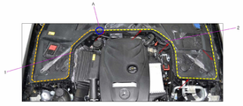
통상, 후드 웨더스트립은 이러한 카울 탑 커버의 전방 상면과 후드의 후방부 하면 사이에 위치하여, 도 1과 같이 카울 탑 커버의 상면과, 카울 탑 커버의 양 측방에 구비되는 펜더 사이드 커버(fender side cover)의 상면에 고정 결합되기도 한다.Normally, the hood weatherstrip is located between the front upper surface of the cowl top cover and the lower surface of the rear portion of the hood, and the fender side cover provided on both sides of the cowl top cover and the cowl top cover as shown in FIG. 1. cover).
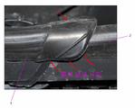
이러한 종래의 후드 웨더스트립(1, 2)은 두 개로 분할되어 각각 결합되는 경우, 도 1의 A 부분을 도시한 도 2와 같이 두 개의 웨더스트립(1, 2)이 단순 덮는 구조로 구비된다.When the
이렇게 두 웨더스트립(1, 2)이 단순 덮히는 구조로 구비되어, 웨더스트립에 의한 실링 성능에 단점이 있고, 두 웨더스트립이 오버랩된 부분의 강건성이 부족하여 후드의 동적 거동을 유발시킬 수가 있다.Thus, the two
그리고, 종래의 웨더스트립은 실링 성능과 탄성을 위해 고무 재질을 압출하여 제작되고, 양 단에는 폴리우레탄(PU) 발포제 등의 엔드피스가 본딩 결합되어 구성된다.And, the conventional weather strip is produced by extruding a rubber material for sealing performance and elasticity, and both ends are configured by bonding end pieces such as polyurethane (PU) foaming agent.
이상의 배경기술에 기재된 사항은 발명의 배경에 대한 이해를 돕기 위한 것으로서, 이 기술이 속하는 분야에서 통상의 지식을 가진 자에게 이미 알려진 종래기술이 아닌 사항을 포함할 수 있다.The above description of the background art is for helping to understand the background of the invention, and may include a non-prior art information that is already known to those of ordinary skill in the art.
본 발명은 상술한 문제점을 해결하고자 안출된 것으로서, 본 발명은 후드 웨더스트립의 결합부에 실링 성능 및 강건성을 강화시킬 수 있는 후드 웨더스트립 어셈블리를 제공하는 데 그 목적이 있다.The present invention has been devised to solve the above-mentioned problems, and the present invention has an object to provide a hood weatherstrip assembly capable of enhancing sealing performance and robustness at a joint portion of a hood weatherstrip.
본 발명의 일 관점에 의한 후드 웨더스트립 어셈블리는, 카울 탑 커버(cowl top cover)에 고정되는 센터스트립 및 상기 센터스트립의 양 단에 각각 결합되고, 각각 펜더 사이드 커버(fender side cover)에 고정되는 한 쌍의 사이드스트립을 포함한다.Hood weatherstrip assembly according to an aspect of the present invention, the center strip is fixed to the cowl top cover (cowl top cover) and coupled to both ends of the center strip, respectively, each is fixed to a fender side cover (fender side cover) Includes a pair of side strips.
그리고, 상기 센터스트립은, 센터 바디와 상기 센터 바디의 양 단에 형성되며 측방으로 개방된 센터 결합부로 구성되는 것을 특징으로 한다.In addition, the center strip is characterized in that it is formed on both ends of the center body and the center body, and is composed of a center coupling portion opened laterally.
또한, 상기 센터 결합부의 외주는 상기 센터 바디의 외주와 동일 형상인 것을 특징으로 한다.In addition, the outer circumference of the center coupling portion is characterized in that the same shape as the outer circumference of the center body.
나아가, 상기 센터 결합부의 내측에는 가이드 돌기가 돌출 형성된 것을 특징으로 한다.Furthermore, a guide projection is formed on the inner side of the center coupling portion.
다음으로, 상기 사이드스트립은, 사이드 바디 및 상기 사이드 바디의 일 단에 구성되어 상기 센터 결합부와 결합되는 사이드 결합부를 포함한다.Next, the side strip includes a side body and a side coupling portion configured at one end of the side body and coupled with the center coupling portion.
그리고, 상기 사이드 결합부는, 상기 사이드 바디와 동일한 외주 형상으로 마련되는 결합 바디 및 상기 결합 바디의 일 측면으로부터 측방으로 돌출 형성되고, 상기 결합 바디의 외주의 크기보다 작은 외주의 크기를 가지며, 상기 센터 결합부에 삽입되는 결합 인써트를 포함한다.In addition, the side coupling portion is formed to protrude laterally from one side of the coupling body and the coupling body provided in the same circumferential shape as the side body, and has a size of an outer circumference smaller than the size of the outer circumference of the coupling body, and the center It includes a coupling insert inserted into the coupling portion.
또한, 상기 결합 인써트에는 챔퍼(chamfer)가 형성된 것을 특징으로 한다.In addition, the coupling insert is characterized in that a chamfer (chamfer) is formed.
나아가, 상기 사이드 바디 타 단에 일체 사출 성형된 엔드피스를 더 포함할 수 있다.Furthermore, an end piece integrally injection-molded to the other end of the side body may be further included.
한편, 상기 사이드스트립은, 사이드 바디와 상기 사이드 바디의 양 단에 형성되며 측방으로 개방된 사이드 결합부로 구성될 수 있다.Meanwhile, the side strip may be formed of a side body and side coupling portions formed at both ends of the side body and opened to the side.
그리고, 사이드 결합부의 외주는 상기 사이드 바디의 외주와 동일 형상일 수 있다.In addition, the outer periphery of the side coupling portion may have the same shape as the outer periphery of the side body.
또한, 상기 센터스트립은, 센터 바디 및 상기 센터 바디의 일 단에 구성되어 상기 사이드 결합부와 결합되는 센터 결합부를 포함할 수 있다.Also, the center strip may include a center body and a center coupling portion configured at one end of the center body and coupled with the side coupling portion.
나아가, 상기 센터 결합부는, 상기 센터 바디와 동일한 외주 형상으로 마련되는 결합 바디 및 상기 결합 바디의 일 측면으로부터 측방으로 돌출 형성되고, 상기 결합 바디의 외주의 크기보다 작은 외주의 크기를 가지며, 상기 사이드 결합부에 삽입되는 결합 인써트를 포함할 수 있다.Furthermore, the center coupling portion is formed to protrude laterally from one side of the coupling body and the coupling body provided in the same outer circumferential shape as the center body, has a size of an outer circumference smaller than the size of the outer circumference of the coupling body, and the side It may include a coupling insert inserted into the coupling portion.
본 발명의 후드 웨더스트립 어셈블리에 의하면, 두 웨더스트립 간 이중실링 구조에 의해 실링 성능 및 강건성이 보다 향상된다.According to the hood weatherstrip assembly of the present invention, the sealing performance and robustness are further improved by the double sealing structure between the two weatherstrips.
그리고, 두 웨더스트립 간 단순히 덮는 구조가 아니므로 외관이 우수하며, 후드의 동적 거동을 유발시키지 않는다.In addition, the appearance is excellent because the structure is not simply covered between the two weatherstrips, and does not induce dynamic behavior of the hood.
또한, 단순 덮히는 구조에 비해 차체 비틀림 모멘트를 감소시킨다.In addition, the torsional moment of the vehicle body is reduced compared to a simple covered structure.
도 1 및 도 2는 종래의 후드 웨더스트립을 도시한 것이다.
도 3은 본 발명의 일 실시예에 의한 후드 웨더스트립 어셈블리를 도시한 것이다.
도 4는 도 3의 B-B 단면을 도시한 것이다.
도 5는 본 발명의 일 구성인 센터스트립을 부분적으로 도시한 것이다.
도 6은 본 발명의 일 구성인 사이드스트립을 부분적으로 도시한 것이다.
도 7은 본 발명의 센터스트립과 사이드스트립 간의 결합을 도시한 것이다.
도 8은 도 7의 결합부를 확대 도시한 것이다.
도 9는 도 8의 D-D 단면을 나타낸 것이다.
도 10 및 도 11은 종래의 후드 웨더스트립에 의한 bending/torsion 모멘트를 설명하기 위한 것이다.
도 12는 본 발명의 후드 웨더스트립 어셈블리에 의한 bending/torsion 모멘트를 설명하기 위한 것이다.1 and 2 show a conventional hood weatherstrip.
Figure 3 shows a hood weatherstrip assembly according to an embodiment of the present invention.
4 is a cross-sectional view of the BB of FIG.
5 partially illustrates a center strip, which is one configuration of the present invention.
6 is a partial view of a side strip, which is one configuration of the present invention.
7 shows the coupling between the center strip and the side strip of the present invention.
8 is an enlarged view of the coupling portion of FIG. 7.
9 is a cross-sectional view of DD of FIG. 8.
10 and 11 are for explaining the bending / torsion moment by the conventional hood weatherstrip.
12 is for explaining the bending / torsion moment by the hood weatherstrip assembly of the present invention.
본 발명과 본 발명의 동작상의 이점 및 본 발명의 실시에 의하여 달성되는 목적을 충분히 이해하기 위해서는 본 발명의 바람직한 실시 예를 예시하는 첨부 도면 및 첨부 도면에 기재된 내용을 참조하여야만 한다.In order to fully understand the present invention, the operational advantages of the present invention, and the objects achieved by the practice of the present invention, reference should be made to the accompanying drawings and the contents described in the accompanying drawings, which illustrate preferred embodiments of the present invention.
본 발명의 바람직한 실시 예를 설명함에 있어서, 본 발명의 요지를 불필요하게 흐릴 수 있는 공지의 기술이나 반복적인 설명은 그 설명을 줄이거나 생략하기로 한다.In describing preferred embodiments of the present invention, well-known techniques or repetitive descriptions that may unnecessarily obscure the subject matter of the present invention will be reduced or omitted.
도 3은 본 발명의 일 실시예에 의한 후드 웨더스트립 어셈블리를 도시한 것이고, 도 4는 도 3의 B-B 단면을 도시한 것이다.3 shows a hood weatherstrip assembly according to an embodiment of the present invention, and FIG. 4 shows a B-B cross section of FIG. 3.
그리고, 도 5는 본 발명의 일 구성인 센터스트립을 부분적으로 도시한 것이고, 도 6은 본 발명의 일 구성인 사이드스트립을 부분적으로 도시한 것이며, 도 7은 본 발명의 센터스트립과 사이드스트립 간의 결합을 도시한 것이다.In addition, FIG. 5 partially shows the center strip, which is one component of the present invention, FIG. 6 partially shows the side strip, which is one component of the present invention, and FIG. 7 is between the center strip and the side strip of the present invention. The combination is illustrated.
이하, 도 3 내지 도 7을 참조하여 본 발명의 일 실시예에 의한 후드 웨더스트립 어셈블리를 설명하기로 한다.Hereinafter, a hood weatherstrip assembly according to an embodiment of the present invention will be described with reference to FIGS. 3 to 7.
본 발명에 의한 후드 웨더스트립 어셈블리는 두 개의 웨더스트립을 단순히 덮는 구조를 탈피하여 실링 성능을 보다 향상시키고, 강건성을 강화할 수 있게 한 후드 웨더스트립 어셈블리이다.The hood weatherstrip assembly according to the present invention is a hood weatherstrip assembly capable of further improving sealing performance and strengthening robustness by breaking the structure of simply covering two weatherstrips.
이를 위한 본 발명의 일 실시예에 의한 후드 웨더스트립 어셈블리는 카울 탑 커버(C, cowl top cover) 상면에 고정 결합되는 센터스트립(10)과, 센터스트립(10)의 양 단에 결합되고 각각 펜더 사이드 커버(S, fender side cover)의 상면에 고정 결합되는 한 쌍의 사이드스트립(20, 30)을 포함하고, 사이드스트립(20, 30)의 끝단에는 엔드피스(23, 33)가 형성된다.The hood weatherstrip assembly according to an embodiment of the present invention for this purpose is coupled to both ends of the
센터스트립(10)과 사이드스트립(20, 30)은 각각의 바디와 바디 하부에 각각 카울 탑 커버(C)와 펜더 사이드 커버(S)와 결합되는 고정부로 구성이 된다.The
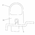
즉, 도 3의 B-B 단면을 도시한 도 4와 같이 사이드스트립(20)의 예를 들면, 사이드 바디(21)는 EPDM 등과 같이 소정의 탄성력과 밀봉성을 가진 재질로 이루어져 후드와의 접촉 시에 후드의 하면과 펜더 사이드 커버(S)의 상면 사이의 이격공간을 밀폐하도록 구성되고, 내부에 중공이 형성됨으로써 탄성력과 밀폐성이 보다 향상될 수 있게 구성된다.That is, as an example of the
그리고, 고정부(24)는 고경도 고무로서, 하면으로부터 상방향으로 홈이 형성되고, 홈 내측으로 돌기가 형성되어 펜더 사이드 커버(S)에 형성된 돌기가 삽입되어 이에 결합이 된다.And, the
이와 같은 바디와 고정부의 구성은 센터스트립 또한 마찬가지이다.The structure of the body and the fixing part is the same with the center strip.
본 발명은 한 쌍의 사이드스트립(20, 30)이 센터스트립(10)에 덮히는 것이 아니라 센터스트립(10)과 결합되는 형태로 어셈블리를 구성한다.The present invention constitutes an assembly in a form in which a pair of
이를 위해, 센터스트립(10)은 센터 바디(11)와 센터 바디(11) 양 단에 구성되는 센터 결합부(12)로 구성되고, 사이드스트립(20, 30)은 사이드 바디(21)와, 사이드 결합부(22)로 구성된다.To this end, the
도 5 내지 도 7은 양 사이드스트립(20, 30) 중 하나만 도시한 것이며, 사이드스트립(20)의 사이드 결합부(22)는 사이드 바디(21)의 일 측에 형성되고, 사이드 바디(21)의 타 측에는 엔드피스(23)가 형성된다.5 to 7 show only one of both
센터스트립(10)은 밀봉성과 탄성력을 가지고 카울 탑 커버(C)에 고정되는 센터 바디(11)와, 양 단에 구성된 센터 결합부(12)에 의해 한 쌍의 사이드스트립(20, 30)과 결합된다.The
센터 결합부(12)는 사이드스트립(20)의 사이드 결합부(22)와의 결합을 위해 측방으로 뚤어져 있고 센터 바디(11)와 동일한 외주 형상으로 마련된다.The
그리고, 도 5의 도시와 같이, 결합의 용이성을 위해 센터 결합부(12) 내측 하면에는 가이드 돌기(12-1)가 돌출 형성된다. 가이드 돌기(12-1)는 필요에 의한 분리시 이탈도 용이하게 할 수 있다.And, as shown in Fig. 5, for ease of coupling, a guide projection 12-1 is formed on the inner lower surface of the
다음, 사이드스트립(20)은 밀봉성과 탄성력을 가지고 펜더 사이드 커버(S)에 고정된 사이드 바디(21)와, 사이드바디(21) 일 단에 구성되는 사이드 결합부(22) 및 사이드 바디(21) 타 단에 구성되는 엔드피스(23)로 구성되어, 사이드 결합부(22)에 의해 센터스트립(10)과 결합이 된다.Next, the
사이드바디(21)는 도시와 같이 펜더 사이드 커버(S)의 형상에 대응되게 평면상 절곡된 형상일 수 있다.
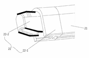
사이드 결합부(22)는 사이드 바디(21)와 동일한 외주 형상으로 마련되는 결합 바디(22-1)와, 결합 바디(22-1)의 일 측면으로부터 측방으로 돌출되고, 결합 바디(22-1)의 외주의 크기보다 작은 외주의 크기를 가지는 결합 인써트(22-2)로 구성되어, 결합 인써트(22-2)가 센터 결합부(12) 내측으로 삽입되어 결합되게 한다.The
결합 인써트(22-2)는 결합 바디(22-1)의 일 측면으로부터 측방향으로 연장 돌출되기 때문에 결합 인써트(22-2)의 외주 크기는 센터 결합부(12)의 내주 크기에 대응되는 크기를 가진다.Since the coupling insert 22-2 protrudes laterally from one side of the coupling body 22-1, the size of the outer circumference of the coupling insert 22-2 corresponds to the size of the inner circumference of the
그러므로, 도 7과 같이 센터스트립(10)과 사이드스트립(20)의 결합시, 도 8의 도시와 같이 결합 인써트(22-2)는 센터 결합부(12)에 완전히 삽입되어 외부로 노출되지 않고, 센터 결합부(12)와 결합 바디(22-1)의 외주의 형상과 크기는 동일하여 외관상 일체를 이룬다.Therefore, when the
또한, 도 8의 D-D 단면을 도시한 도 9와 같이 결합 인써트(22-2)는 센터 결합부(12) 내측면과 접하고, 센터 결합부(12) 및 결합 바디(22-1) 간 접함으로써 이중 실링 맞대기 구조를 형성하여 실링 성능 및 강건성을 보다 향상시킬 수가 있다.In addition, as shown in FIG. 9 showing the DD cross-section of FIG. 8, the coupling insert 22-2 is in contact with the inner surface of the
본 발명의 일 실시예에서는 센터 스트립(10)의 센터 결합부(12)에 사이드 스트립(20)의 사이드 결합부(22)가 삽입되는 것으로 기재하였으나, 이와 반대로 결합 구조를 형성할 수도 있다.In one embodiment of the present invention, the
즉, 센터 스트립(10)에 측방으로 돌출된 결합 인써트(22-2)를 포함하는 센터 결합부가 형성되고, 사이드 스트립(20) 일 측에 형성되는 사이드 결합부가 측방으로 개방되어 사이드 결합부에 센터 스트립의 결합 인써트가 삽입되어 결합되는 구조로도 가능하다.That is, a center coupling portion including a coupling insert 22-2 protruding laterally to the
나아가, 결합 인써트(22-2)는 도 6의 도시와 같이 결합의 용이성을 위해 상면이나 하면, 또는 측면에 챔퍼(chamfer)가 형성될 수 있고, 본 발명의 일 예에서는 상면과 하면에 형성된 것을 도시하였다.Further, the coupling insert 22-2 may be formed with a chamfer on the upper surface or the lower surface, or the side surface for ease of coupling, as shown in FIG. 6, and in one example of the present invention, the upper surface and the lower surface may be formed. Shown.
한편, 센터스트립(10)의 센터 바디(11)와 사이드스트립(20, 30)의 사이드 바디(21)는 EPDM 등과 같이 소정의 탄성력과 밀봉성을 가진 재질을 스트립 형상으로 압출 공정에 의해 제조한다.On the other hand, the
그리고, 센터 결합부(12)는 사출 공정에 의해 센터 바디(11)에 일체로 형성시키고, 사이드 결합부(22)도 사출 공정에 의해 사이드 바디(21)에 일체로 형성시킨다.Then, the
또한, 한 쌍의 사이드스트립(20, 30)에서 사이드 바디(21)의 일 단에 각각 형성되는 엔드피스(23)를 사이드 바디(21)에 일체로 사출성형하여 제작한다.In addition, the
이와 같이, 본 발명의 후드 웨더스트립 어셈블리의 센터 결합부, 사이드 결합부 및 엔드피스는 기존과 달리 사출성형에 의해 각 바디에 일체화시킴으로써 기존 보다 외관의 상품성이 증대되고, 접합력이 강화되어 강건성을 향상시킬 수 있다.As described above, the center coupling portion, the side coupling portion, and the end piece of the hood weatherstrip assembly of the present invention are integrated into each body by injection molding, unlike the conventional one, thereby increasing the merchandise of the appearance and strengthening the bonding strength by strengthening the bonding force. I can do it.
다음으로, 도 10 및 도 11은 종래의 후드 웨더스트립에 의한 bending/torsion 모멘트를 설명하기 위한 것이고, 도 12는 본 발명의 후드 웨더스트립 어셈블리에 의한 bending/torsion 모멘트를 설명하기 위한 것이다.Next, FIGS. 10 and 11 are for explaining the bending / torsion moment by the conventional hood weatherstrip, and FIG. 12 is for explaining the bending / torsion moment by the hood weatherstrip assembly of the present invention.
이를 참조하면, 굽힘/벤딩(Bending/Torsion) 모멘트 값은 도 12의 본 발명에 의한 경우 더욱 크게 나오는 구조이다.Referring to this, the bending / bending (Bending / Torsion) moment value has a larger structure in the case of the present invention of FIG. 12.
도 10의 종래의 경우에는 웨더스트립이 후드 이너판넬에 경사각에 따라 눌려지는 부분이 힌지(hinge, 고정점)로부터 멀어지는 방향으로 변형되어 굽힘강성이 나빠지는 방향인 반면, 본 발명의 경우에는 웨더스트립 간 결합부분이 끼움 구조가 적용되어 닫힌 방향의 역방향으로 견디는 구조로 굽힙 및 벤딩에 강한 구조인 것이다.In the conventional case of Fig. 10, the weather strip is deformed in a direction away from the hinge (fixed point) in the direction in which the weather strip is pressed according to the inclination angle to the hood inner panel, whereas the bending strength is worse. It is a structure that is resistant to bending and bending with a structure where the inter-engagement part is fitted with a fitting structure to withstand the direction in the closed direction.
이상과 같은 본 발명은 예시된 도면을 참조하여 설명되었지만, 기재된 실시 예에 한정되는 것이 아니고, 본 발명의 사상 및 범위를 벗어나지 않고 다양하게 수정 및 변형될 수 있음은 이 기술의 분야에서 통상의 지식을 가진 자에게 자명하다. 따라서 그러한 수정 예 또는 변형 예들은 본 발명의 특허청구범위에 속한다 하여야 할 것이며, 본 발명의 권리범위는 첨부된 특허청구범위에 기초하여 해석되어야 할 것이다.Although the present invention as described above has been described with reference to the illustrated drawings, it is not limited to the described embodiments, and it can be modified and modified in various ways without departing from the spirit and scope of the present invention. It is obvious to those who have it. Therefore, such modifications or variations will have to belong to the claims of the present invention, the scope of the present invention should be interpreted based on the appended claims.
10 : 센터스트립
11 : 센터 바디
12 : 센터 결합부
12-1 : 가이드 돌기
20, 30 : 사이드스트립
21 : 사이드 바디
22 : 사이드 결합부
22-1 : 결합 바디
22-2 : 결합 인써트
23, 33 : 엔드피스
24 : 고정부10: Center strip
11: Center body
12: center coupling
12-1: Guide projection
20, 30: side strip
21: side body
22: side coupling
22-1: Combined body
22-2: Combined insert
23, 33: end piece
24: fixing part
Claims (12)
상기 센터스트립의 양 단에 각각 결합되고, 각각 펜더 사이드 커버(fender side cover)에 고정되는 한 쌍의 사이드스트립을 포함하는,
후드 웨더스트립 어셈블리.A center strip fixed to a cowl top cover; And
Each coupled to both ends of the center strip, each comprising a pair of side strips fixed to a fender side cover (fender side cover),
Hood weatherstrip assembly.
상기 센터스트립은, 센터 바디와 상기 센터 바디의 양 단에 형성되며 측방으로 개방된 센터 결합부로 구성되는 것을 특징으로 하는,
후드 웨더스트립 어셈블리.The method according to claim 1,
The center strip is formed on both ends of the center body and the center body, characterized in that it consists of a center coupling portion open to the side,
Hood weatherstrip assembly.
상기 센터 결합부의 외주는 상기 센터 바디의 외주와 동일 형상인 것을 특징으로 하는,
후드 웨더스트립 어셈블리.The method according to claim 2,
The outer circumference of the center coupling portion is characterized in that the same shape as the outer circumference of the center body,
Hood weatherstrip assembly.
상기 센터 결합부의 내측에는 가이드 돌기가 돌출 형성된 것을 특징으로 하는,
후드 웨더스트립 어셈블리.The method according to claim 3,
Characterized in that the guide projection is formed protruding inside the center coupling portion,
Hood weatherstrip assembly.
상기 사이드스트립은,
사이드 바디; 및
상기 사이드 바디의 일 단에 구성되어 상기 센터 결합부와 결합되는 사이드 결합부를 포함하는,
후드 웨더스트립 어셈블리.The method according to claim 2,
The side strip,
Side body; And
It is configured on one end of the side body and includes a side coupling portion coupled to the center coupling portion,
Hood weatherstrip assembly.
상기 사이드 결합부는,
상기 사이드 바디와 동일한 외주 형상으로 마련되는 결합 바디; 및
상기 결합 바디의 일 측면으로부터 측방으로 돌출 형성되고, 상기 결합 바디의 외주의 크기보다 작은 외주의 크기를 가지며, 상기 센터 결합부에 삽입되는 결합 인써트를 포함하는,
후드 웨더스트립 어셈블리.The method according to claim 5,
The side coupling portion,
A coupling body provided in the same outer circumferential shape as the side body; And
It is formed protruding sideways from one side of the coupling body, has a size of the outer periphery smaller than the size of the outer periphery of the coupling body, including a coupling insert inserted into the center coupling portion,
Hood weatherstrip assembly.
상기 결합 인써트에는 챔퍼(chamfer)가 형성된 것을 특징으로 하는,
후드 웨더스트립 어셈블리.The method according to claim 6,
The coupling insert is characterized in that a chamfer (chamfer) is formed,
Hood weatherstrip assembly.
상기 사이드 바디 타 단에 일체 사출 성형된 엔드피스를 더 포함하는,
후드 웨더스트립 어셈블리.The method according to claim 7,
Further comprising an endpiece integrally injection molded at the other end of the side body,
Hood weatherstrip assembly.
상기 사이드스트립은, 사이드 바디와 상기 사이드 바디의 양 단에 형성되며 측방으로 개방된 사이드 결합부로 구성되는 것을 특징으로 하는,
후드 웨더스트립 어셈블리.The method according to claim 1,
The side strip is formed on both ends of the side body and the side body, characterized in that it consists of a side engagement portion open to the side,
Hood weatherstrip assembly.
사이드 결합부의 외주는 상기 사이드 바디의 외주와 동일 형상인 것을 특징으로 하는,
후드 웨더스트립 어셈블리.The method according to claim 9,
The outer periphery of the side coupling portion is characterized in that the same shape as the outer periphery of the side body,
Hood weatherstrip assembly.
상기 센터스트립은,
센터 바디; 및
상기 센터 바디의 일 단에 구성되어 상기 사이드 결합부와 결합되는 센터 결합부를 포함하는,
후드 웨더스트립 어셈블리.The method according to claim 9,
The center strip,
Center body; And
It is configured on one end of the center body and includes a center coupling portion coupled to the side coupling portion,
Hood weatherstrip assembly.
상기 센터 결합부는,
상기 센터 바디와 동일한 외주 형상으로 마련되는 결합 바디; 및
상기 결합 바디의 일 측면으로부터 측방으로 돌출 형성되고, 상기 결합 바디의 외주의 크기보다 작은 외주의 크기를 가지며, 상기 사이드 결합부에 삽입되는 결합 인써트를 포함하는,
후드 웨더스트립 어셈블리.The method according to claim 11,
The center coupling portion,
A coupling body provided in the same outer circumferential shape as the center body; And
Protruding sideways from one side of the engaging body, having a size of the outer periphery smaller than the size of the outer periphery of the engaging body, including a coupling insert inserted into the side engaging portion,
Hood weatherstrip assembly.
Priority Applications (4)
| Application Number | Priority Date | Filing Date | Title |
|---|---|---|---|
| KR1020180130606A KR102621908B1 (en) | 2018-10-30 | 2018-10-30 | Hood weather-strip assembly |
| US16/439,358 US11142055B2 (en) | 2018-10-30 | 2019-06-12 | Hood weather strip assembly |
| DE102019208877.5A DE102019208877A1 (en) | 2018-10-30 | 2019-06-19 | BONNET SEAL ARRANGEMENT BACKGROUND |
| CN201910535093.0A CN111114460A (en) | 2018-10-30 | 2019-06-20 | hood seal assembly |
Applications Claiming Priority (1)
| Application Number | Priority Date | Filing Date | Title |
|---|---|---|---|
| KR1020180130606A KR102621908B1 (en) | 2018-10-30 | 2018-10-30 | Hood weather-strip assembly |
Publications (2)
| Publication Number | Publication Date |
|---|---|
| KR20200048470A true KR20200048470A (en) | 2020-05-08 |
| KR102621908B1 KR102621908B1 (en) | 2024-01-05 |
Family
ID=70325005
Family Applications (1)
| Application Number | Title | Priority Date | Filing Date |
|---|---|---|---|
| KR1020180130606A Active KR102621908B1 (en) | 2018-10-30 | 2018-10-30 | Hood weather-strip assembly |
Country Status (4)
| Country | Link |
|---|---|
| US (1) | US11142055B2 (en) |
| KR (1) | KR102621908B1 (en) |
| CN (1) | CN111114460A (en) |
| DE (1) | DE102019208877A1 (en) |
Families Citing this family (2)
| Publication number | Priority date | Publication date | Assignee | Title |
|---|---|---|---|---|
| JP1665813S (en) * | 2019-07-19 | 2020-08-11 | ||
| IT202300022515A1 (en) * | 2023-10-26 | 2025-04-26 | Stellantis Europe Spa | "FRONT HOOD OF A MOTOR VEHICLE EQUIPPED WITH A REINFORCING COMPONENT" |
Citations (4)
| Publication number | Priority date | Publication date | Assignee | Title |
|---|---|---|---|---|
| KR20090111395A (en) * | 2008-04-22 | 2009-10-27 | 현대자동차주식회사 | Spare tire carrier of vehicle |
| US20100307065A1 (en) * | 2008-02-01 | 2010-12-09 | BSH Bosch und Siemens Hausgeräte GmbH | Refrigeration device having a seal element in the form of a hollow profile |
| US20130221705A1 (en) * | 2011-08-31 | 2013-08-29 | Nishikawa Rubber Co., Ltd. | Body front structure for automobile |
| KR20160099260A (en) | 2015-02-12 | 2016-08-22 | 현대자동차주식회사 | Hood weatherstrip and assembled structure of the hood weatherstrip |
Family Cites Families (17)
| Publication number | Priority date | Publication date | Assignee | Title |
|---|---|---|---|---|
| GB1460169A (en) * | 1974-03-13 | 1976-12-31 | Schlegel Uk Ltd | Moulded corners or joints of door seals and the like |
| US4956941A (en) * | 1989-01-12 | 1990-09-18 | The Standard Products Company | Front loading flush glass run system |
| DE29720053U1 (en) * | 1997-11-12 | 1999-03-18 | Meteor Gummiwerke K. H. Bädje GmbH & Co, 31167 Bockenem | Seal connector, seal end piece and seal |
| US7219953B2 (en) * | 2005-03-11 | 2007-05-22 | Nissan Technical Center North America, Inc. | Cowl cover with integrated washer fluid passageway |
| US7316447B2 (en) * | 2005-04-08 | 2008-01-08 | Gdx North America, Inc. | Integrated motor vehicle cowl vent and seal |
| JP2007118638A (en) * | 2005-10-25 | 2007-05-17 | Mazda Motor Corp | Vehicle hood seal structure |
| JP5347313B2 (en) * | 2008-04-18 | 2013-11-20 | スズキ株式会社 | Vehicle cowl structure |
| DE202008006986U1 (en) * | 2008-05-23 | 2009-10-01 | Elkamet Kunststofftechnik Gmbh | Profile element for connecting a vehicle window with a water tank |
| KR20110054941A (en) * | 2009-11-19 | 2011-05-25 | 현대자동차주식회사 | Combined structure of car front body frame |
| CN102371876A (en) * | 2010-08-24 | 2012-03-14 | 上海阿文美驰汽车部件有限公司 | Sealing bar for skylight |
| US8573682B2 (en) * | 2011-11-04 | 2013-11-05 | Shape Corp. | Vehicle cowl components adapted for hood/fender sealing |
| FR2986767B1 (en) * | 2012-02-13 | 2014-03-14 | Renault Sa | ARRANGEMENT FOR A MOTOR VEHICLE WITH A WATER BOX IN THREE ELEMENTS |
| US20150068128A1 (en) * | 2013-09-06 | 2015-03-12 | U.S. Farathane Corporation | Tri-extruded collapsible polygoral compression seal for vehicle applications |
| CN204173011U (en) * | 2014-09-29 | 2015-02-25 | 上汽通用五菱汽车股份有限公司 | A kind of vehicle body machinery space of hermetically-sealed construction |
| KR101765637B1 (en) * | 2016-03-08 | 2017-08-07 | 현대자동차 주식회사 | Vehicle body structure using CFRP |
| US9731776B1 (en) * | 2016-03-24 | 2017-08-15 | Toyota Motor Engineering & Manufacturing North America, Inc. | Bumper gap aerodynamic seal |
| US10800228B2 (en) * | 2018-04-12 | 2020-10-13 | Ford Global Technologies, Llc | Leaf screen and method of making the leaf screen with co-molded seal and bump stop |
-
2018
- 2018-10-30 KR KR1020180130606A patent/KR102621908B1/en active Active
-
2019
- 2019-06-12 US US16/439,358 patent/US11142055B2/en active Active
- 2019-06-19 DE DE102019208877.5A patent/DE102019208877A1/en active Pending
- 2019-06-20 CN CN201910535093.0A patent/CN111114460A/en active Pending
Patent Citations (4)
| Publication number | Priority date | Publication date | Assignee | Title |
|---|---|---|---|---|
| US20100307065A1 (en) * | 2008-02-01 | 2010-12-09 | BSH Bosch und Siemens Hausgeräte GmbH | Refrigeration device having a seal element in the form of a hollow profile |
| KR20090111395A (en) * | 2008-04-22 | 2009-10-27 | 현대자동차주식회사 | Spare tire carrier of vehicle |
| US20130221705A1 (en) * | 2011-08-31 | 2013-08-29 | Nishikawa Rubber Co., Ltd. | Body front structure for automobile |
| KR20160099260A (en) | 2015-02-12 | 2016-08-22 | 현대자동차주식회사 | Hood weatherstrip and assembled structure of the hood weatherstrip |
Also Published As
| Publication number | Publication date |
|---|---|
| US11142055B2 (en) | 2021-10-12 |
| DE102019208877A1 (en) | 2020-04-30 |
| KR102621908B1 (en) | 2024-01-05 |
| CN111114460A (en) | 2020-05-08 |
| US20200130490A1 (en) | 2020-04-30 |
Similar Documents
| Publication | Publication Date | Title |
|---|---|---|
| US10035410B2 (en) | Parting seal and sealing structure of parting portion | |
| JP7166286B2 (en) | Weather strip and its assembly structure | |
| JP5115370B2 (en) | Automotive door seals | |
| US6644718B2 (en) | Structure of roof-side portion of motor vehicle | |
| US20090001772A1 (en) | Foof weather strip | |
| JP2020090232A (en) | Seal structure of vehicle | |
| KR20200048470A (en) | Hood weather-strip assembly | |
| CN206336111U (en) | Boundary seal and the sealing structure in boundary portion | |
| JP2002103985A (en) | Door weatherstrip with seal lip | |
| JP2006123633A (en) | Weather strip for fixed glass | |
| JP4175044B2 (en) | Automotive door weather strip | |
| CN218536318U (en) | Sealing structure for end part of sealing strip outside window of frameless vehicle door | |
| JP5645563B2 (en) | Mounting structure for automotive door weatherstrip | |
| CN104827982A (en) | Weather strip mounted on cover for automotive vehicle | |
| JP6051918B2 (en) | Vehicle door sash structure | |
| JP5096823B2 (en) | Automotive weatherstrip | |
| JP5204039B2 (en) | Door weather strip mounting structure | |
| JP6652473B2 (en) | Automotive roof side weather strip | |
| JP4098591B2 (en) | Automotive weatherstrip | |
| JP7424902B2 (en) | Automotive seal structure | |
| JP3376803B2 (en) | Car door sash molding mounting structure | |
| JP3778196B2 (en) | Glass run assembly structure | |
| JP7248598B2 (en) | Vehicle seal structure | |
| JP2009154642A (en) | Automotive weatherstrip | |
| JP2009096458A (en) | Door weather strip |
Legal Events
| Date | Code | Title | Description |
|---|---|---|---|
| PA0109 | Patent application |
Patent event code: PA01091R01D Comment text: Patent Application Patent event date: 20181030 |
|
| PG1501 | Laying open of application | ||
| A201 | Request for examination | ||
| PA0201 | Request for examination |
Patent event code: PA02012R01D Patent event date: 20210914 Comment text: Request for Examination of Application Patent event code: PA02011R01I Patent event date: 20181030 Comment text: Patent Application |
|
| E902 | Notification of reason for refusal | ||
| PE0902 | Notice of grounds for rejection |
Comment text: Notification of reason for refusal Patent event date: 20221122 Patent event code: PE09021S01D |
|
| E902 | Notification of reason for refusal | ||
| PE0902 | Notice of grounds for rejection |
Comment text: Notification of reason for refusal Patent event date: 20230524 Patent event code: PE09021S01D |
|
| E701 | Decision to grant or registration of patent right | ||
| PE0701 | Decision of registration |
Patent event code: PE07011S01D Comment text: Decision to Grant Registration Patent event date: 20231121 |
|
| GRNT | Written decision to grant | ||
| PR0701 | Registration of establishment |
Comment text: Registration of Establishment Patent event date: 20240102 Patent event code: PR07011E01D |
|
| PR1002 | Payment of registration fee |
Payment date: 20240103 End annual number: 3 Start annual number: 1 |
|
| PG1601 | Publication of registration |