KR20200057777A - Remotely steerable aviation bomb - Google Patents
Remotely steerable aviation bomb Download PDFInfo
- Publication number
- KR20200057777A KR20200057777A KR1020207012796A KR20207012796A KR20200057777A KR 20200057777 A KR20200057777 A KR 20200057777A KR 1020207012796 A KR1020207012796 A KR 1020207012796A KR 20207012796 A KR20207012796 A KR 20207012796A KR 20200057777 A KR20200057777 A KR 20200057777A
- Authority
- KR
- South Korea
- Prior art keywords
- shell
- target
- ground
- wing
- remote control
- Prior art date
- Legal status (The legal status is an assumption and is not a legal conclusion. Google has not performed a legal analysis and makes no representation as to the accuracy of the status listed.)
- Granted
Links
Images








Classifications
-
- F—MECHANICAL ENGINEERING; LIGHTING; HEATING; WEAPONS; BLASTING
- F42—AMMUNITION; BLASTING
- F42B—EXPLOSIVE CHARGES, e.g. FOR BLASTING, FIREWORKS, AMMUNITION
- F42B10/00—Means for influencing, e.g. improving, the aerodynamic properties of projectiles or missiles; Arrangements on projectiles or missiles for stabilising, steering, range-reducing, range-increasing or fall-retarding
- F42B10/02—Stabilising arrangements
- F42B10/14—Stabilising arrangements using fins spread or deployed after launch, e.g. after leaving the barrel
-
- F—MECHANICAL ENGINEERING; LIGHTING; HEATING; WEAPONS; BLASTING
- F42—AMMUNITION; BLASTING
- F42B—EXPLOSIVE CHARGES, e.g. FOR BLASTING, FIREWORKS, AMMUNITION
- F42B10/00—Means for influencing, e.g. improving, the aerodynamic properties of projectiles or missiles; Arrangements on projectiles or missiles for stabilising, steering, range-reducing, range-increasing or fall-retarding
- F42B10/32—Range-reducing or range-increasing arrangements; Fall-retarding means
- F42B10/38—Range-increasing arrangements
-
- F—MECHANICAL ENGINEERING; LIGHTING; HEATING; WEAPONS; BLASTING
- F42—AMMUNITION; BLASTING
- F42B—EXPLOSIVE CHARGES, e.g. FOR BLASTING, FIREWORKS, AMMUNITION
- F42B10/00—Means for influencing, e.g. improving, the aerodynamic properties of projectiles or missiles; Arrangements on projectiles or missiles for stabilising, steering, range-reducing, range-increasing or fall-retarding
- F42B10/60—Steering arrangements
- F42B10/62—Steering by movement of flight surfaces
-
- F—MECHANICAL ENGINEERING; LIGHTING; HEATING; WEAPONS; BLASTING
- F42—AMMUNITION; BLASTING
- F42B—EXPLOSIVE CHARGES, e.g. FOR BLASTING, FIREWORKS, AMMUNITION
- F42B12/00—Projectiles, missiles or mines characterised by the warhead, the intended effect, or the material
- F42B12/02—Projectiles, missiles or mines characterised by the warhead, the intended effect, or the material characterised by the warhead or the intended effect
-
- F—MECHANICAL ENGINEERING; LIGHTING; HEATING; WEAPONS; BLASTING
- F42—AMMUNITION; BLASTING
- F42B—EXPLOSIVE CHARGES, e.g. FOR BLASTING, FIREWORKS, AMMUNITION
- F42B12/00—Projectiles, missiles or mines characterised by the warhead, the intended effect, or the material
- F42B12/02—Projectiles, missiles or mines characterised by the warhead, the intended effect, or the material characterised by the warhead or the intended effect
- F42B12/20—Projectiles, missiles or mines characterised by the warhead, the intended effect, or the material characterised by the warhead or the intended effect of high-explosive type
-
- F—MECHANICAL ENGINEERING; LIGHTING; HEATING; WEAPONS; BLASTING
- F42—AMMUNITION; BLASTING
- F42B—EXPLOSIVE CHARGES, e.g. FOR BLASTING, FIREWORKS, AMMUNITION
- F42B12/00—Projectiles, missiles or mines characterised by the warhead, the intended effect, or the material
- F42B12/02—Projectiles, missiles or mines characterised by the warhead, the intended effect, or the material characterised by the warhead or the intended effect
- F42B12/36—Projectiles, missiles or mines characterised by the warhead, the intended effect, or the material characterised by the warhead or the intended effect for dispensing materials; for producing chemical or physical reaction; for signalling ; for transmitting information
- F42B12/365—Projectiles transmitting information to a remote location using optical or electronic means
-
- F—MECHANICAL ENGINEERING; LIGHTING; HEATING; WEAPONS; BLASTING
- F42—AMMUNITION; BLASTING
- F42B—EXPLOSIVE CHARGES, e.g. FOR BLASTING, FIREWORKS, AMMUNITION
- F42B12/00—Projectiles, missiles or mines characterised by the warhead, the intended effect, or the material
- F42B12/02—Projectiles, missiles or mines characterised by the warhead, the intended effect, or the material characterised by the warhead or the intended effect
- F42B12/36—Projectiles, missiles or mines characterised by the warhead, the intended effect, or the material characterised by the warhead or the intended effect for dispensing materials; for producing chemical or physical reaction; for signalling ; for transmitting information
- F42B12/42—Projectiles, missiles or mines characterised by the warhead, the intended effect, or the material characterised by the warhead or the intended effect for dispensing materials; for producing chemical or physical reaction; for signalling ; for transmitting information of illuminating type, e.g. carrying flares
-
- F—MECHANICAL ENGINEERING; LIGHTING; HEATING; WEAPONS; BLASTING
- F42—AMMUNITION; BLASTING
- F42B—EXPLOSIVE CHARGES, e.g. FOR BLASTING, FIREWORKS, AMMUNITION
- F42B12/00—Projectiles, missiles or mines characterised by the warhead, the intended effect, or the material
- F42B12/02—Projectiles, missiles or mines characterised by the warhead, the intended effect, or the material characterised by the warhead or the intended effect
- F42B12/36—Projectiles, missiles or mines characterised by the warhead, the intended effect, or the material characterised by the warhead or the intended effect for dispensing materials; for producing chemical or physical reaction; for signalling ; for transmitting information
- F42B12/46—Projectiles, missiles or mines characterised by the warhead, the intended effect, or the material characterised by the warhead or the intended effect for dispensing materials; for producing chemical or physical reaction; for signalling ; for transmitting information for dispensing gases, vapours, powders or chemically-reactive substances
-
- F—MECHANICAL ENGINEERING; LIGHTING; HEATING; WEAPONS; BLASTING
- F42—AMMUNITION; BLASTING
- F42B—EXPLOSIVE CHARGES, e.g. FOR BLASTING, FIREWORKS, AMMUNITION
- F42B12/00—Projectiles, missiles or mines characterised by the warhead, the intended effect, or the material
- F42B12/02—Projectiles, missiles or mines characterised by the warhead, the intended effect, or the material characterised by the warhead or the intended effect
- F42B12/36—Projectiles, missiles or mines characterised by the warhead, the intended effect, or the material characterised by the warhead or the intended effect for dispensing materials; for producing chemical or physical reaction; for signalling ; for transmitting information
- F42B12/46—Projectiles, missiles or mines characterised by the warhead, the intended effect, or the material characterised by the warhead or the intended effect for dispensing materials; for producing chemical or physical reaction; for signalling ; for transmitting information for dispensing gases, vapours, powders or chemically-reactive substances
- F42B12/50—Projectiles, missiles or mines characterised by the warhead, the intended effect, or the material characterised by the warhead or the intended effect for dispensing materials; for producing chemical or physical reaction; for signalling ; for transmitting information for dispensing gases, vapours, powders or chemically-reactive substances by dispersion
-
- F—MECHANICAL ENGINEERING; LIGHTING; HEATING; WEAPONS; BLASTING
- F42—AMMUNITION; BLASTING
- F42B—EXPLOSIVE CHARGES, e.g. FOR BLASTING, FIREWORKS, AMMUNITION
- F42B15/00—Self-propelled projectiles or missiles, e.g. rockets; Guided missiles
- F42B15/01—Arrangements thereon for guidance or control
-
- F—MECHANICAL ENGINEERING; LIGHTING; HEATING; WEAPONS; BLASTING
- F42—AMMUNITION; BLASTING
- F42B—EXPLOSIVE CHARGES, e.g. FOR BLASTING, FIREWORKS, AMMUNITION
- F42B15/00—Self-propelled projectiles or missiles, e.g. rockets; Guided missiles
- F42B15/08—Self-propelled projectiles or missiles, e.g. rockets; Guided missiles for carrying measuring instruments; Arrangements for mounting sensitive cargo within a projectile; Arrangements for acoustic sensitive cargo within a projectile
-
- F—MECHANICAL ENGINEERING; LIGHTING; HEATING; WEAPONS; BLASTING
- F42—AMMUNITION; BLASTING
- F42B—EXPLOSIVE CHARGES, e.g. FOR BLASTING, FIREWORKS, AMMUNITION
- F42B15/00—Self-propelled projectiles or missiles, e.g. rockets; Guided missiles
- F42B15/10—Missiles having a trajectory only in the air
-
- F—MECHANICAL ENGINEERING; LIGHTING; HEATING; WEAPONS; BLASTING
- F42—AMMUNITION; BLASTING
- F42B—EXPLOSIVE CHARGES, e.g. FOR BLASTING, FIREWORKS, AMMUNITION
- F42B25/00—Fall bombs
-
- F—MECHANICAL ENGINEERING; LIGHTING; HEATING; WEAPONS; BLASTING
- F42—AMMUNITION; BLASTING
- F42C—AMMUNITION FUZES; ARMING OR SAFETY MEANS THEREFOR
- F42C1/00—Impact fuzes, i.e. fuzes actuated only by ammunition impact
-
- F—MECHANICAL ENGINEERING; LIGHTING; HEATING; WEAPONS; BLASTING
- F42—AMMUNITION; BLASTING
- F42C—AMMUNITION FUZES; ARMING OR SAFETY MEANS THEREFOR
- F42C13/00—Proximity fuzes; Fuzes for remote detonation
- F42C13/04—Proximity fuzes; Fuzes for remote detonation operated by radio waves
-
- F—MECHANICAL ENGINEERING; LIGHTING; HEATING; WEAPONS; BLASTING
- F42—AMMUNITION; BLASTING
- F42C—AMMUNITION FUZES; ARMING OR SAFETY MEANS THEREFOR
- F42C13/00—Proximity fuzes; Fuzes for remote detonation
- F42C13/04—Proximity fuzes; Fuzes for remote detonation operated by radio waves
- F42C13/047—Remotely actuated projectile fuzes operated by radio transmission links
-
- G—PHYSICS
- G05—CONTROLLING; REGULATING
- G05D—SYSTEMS FOR CONTROLLING OR REGULATING NON-ELECTRIC VARIABLES
- G05D1/00—Control of position, course, altitude or attitude of land, water, air or space vehicles, e.g. using automatic pilots
- G05D1/0011—Control of position, course, altitude or attitude of land, water, air or space vehicles, e.g. using automatic pilots associated with a remote control arrangement
- G05D1/0022—Control of position, course, altitude or attitude of land, water, air or space vehicles, e.g. using automatic pilots associated with a remote control arrangement characterised by the communication link
-
- G—PHYSICS
- G05—CONTROLLING; REGULATING
- G05D—SYSTEMS FOR CONTROLLING OR REGULATING NON-ELECTRIC VARIABLES
- G05D1/00—Control of position, course, altitude or attitude of land, water, air or space vehicles, e.g. using automatic pilots
- G05D1/0011—Control of position, course, altitude or attitude of land, water, air or space vehicles, e.g. using automatic pilots associated with a remote control arrangement
- G05D1/0038—Control of position, course, altitude or attitude of land, water, air or space vehicles, e.g. using automatic pilots associated with a remote control arrangement by providing the operator with simple or augmented images from one or more cameras located onboard the vehicle, e.g. tele-operation
-
- G—PHYSICS
- G05—CONTROLLING; REGULATING
- G05D—SYSTEMS FOR CONTROLLING OR REGULATING NON-ELECTRIC VARIABLES
- G05D1/00—Control of position, course, altitude or attitude of land, water, air or space vehicles, e.g. using automatic pilots
- G05D1/12—Target-seeking control
-
- G—PHYSICS
- G05—CONTROLLING; REGULATING
- G05D—SYSTEMS FOR CONTROLLING OR REGULATING NON-ELECTRIC VARIABLES
- G05D1/00—Control of position, course, altitude or attitude of land, water, air or space vehicles, e.g. using automatic pilots
- G05D1/20—Control system inputs
- G05D1/22—Command input arrangements
- G05D1/221—Remote-control arrangements
- G05D1/222—Remote-control arrangements operated by humans
- G05D1/224—Output arrangements on the remote controller, e.g. displays, haptics or speakers
-
- G—PHYSICS
- G05—CONTROLLING; REGULATING
- G05D—SYSTEMS FOR CONTROLLING OR REGULATING NON-ELECTRIC VARIABLES
- G05D1/00—Control of position, course, altitude or attitude of land, water, air or space vehicles, e.g. using automatic pilots
- G05D1/20—Control system inputs
- G05D1/22—Command input arrangements
- G05D1/221—Remote-control arrangements
- G05D1/226—Communication links with the remote-control arrangements
-
- G—PHYSICS
- G05—CONTROLLING; REGULATING
- G05D—SYSTEMS FOR CONTROLLING OR REGULATING NON-ELECTRIC VARIABLES
- G05D1/00—Control of position, course, altitude or attitude of land, water, air or space vehicles, e.g. using automatic pilots
- G05D1/20—Control system inputs
- G05D1/24—Arrangements for determining position or orientation
- G05D1/247—Arrangements for determining position or orientation using signals provided by artificial sources external to the vehicle, e.g. navigation beacons
- G05D1/249—Arrangements for determining position or orientation using signals provided by artificial sources external to the vehicle, e.g. navigation beacons from positioning sensors located off-board the vehicle, e.g. from cameras
-
- H—ELECTRICITY
- H04—ELECTRIC COMMUNICATION TECHNIQUE
- H04N—PICTORIAL COMMUNICATION, e.g. TELEVISION
- H04N7/00—Television systems
- H04N7/18—Closed-circuit television [CCTV] systems, i.e. systems in which the video signal is not broadcast
- H04N7/183—Closed-circuit television [CCTV] systems, i.e. systems in which the video signal is not broadcast for receiving images from a single remote source
- H04N7/185—Closed-circuit television [CCTV] systems, i.e. systems in which the video signal is not broadcast for receiving images from a single remote source from a mobile camera, e.g. for remote control
-
- G—PHYSICS
- G05—CONTROLLING; REGULATING
- G05D—SYSTEMS FOR CONTROLLING OR REGULATING NON-ELECTRIC VARIABLES
- G05D2105/00—Specific applications of the controlled vehicles
- G05D2105/35—Specific applications of the controlled vehicles for combat
-
- G—PHYSICS
- G05—CONTROLLING; REGULATING
- G05D—SYSTEMS FOR CONTROLLING OR REGULATING NON-ELECTRIC VARIABLES
- G05D2109/00—Types of controlled vehicles
- G05D2109/20—Aircraft, e.g. drones
- G05D2109/285—Projectiles
Landscapes
- Engineering & Computer Science (AREA)
- General Engineering & Computer Science (AREA)
- Chemical & Material Sciences (AREA)
- Combustion & Propulsion (AREA)
- Physics & Mathematics (AREA)
- Aviation & Aerospace Engineering (AREA)
- Remote Sensing (AREA)
- Radar, Positioning & Navigation (AREA)
- General Physics & Mathematics (AREA)
- Automation & Control Theory (AREA)
- Fluid Mechanics (AREA)
- Multimedia (AREA)
- Signal Processing (AREA)
- Dispersion Chemistry (AREA)
- Electric Clocks (AREA)
- Toys (AREA)
- Aiming, Guidance, Guns With A Light Source, Armor, Camouflage, And Targets (AREA)
- Selective Calling Equipment (AREA)
- Thermotherapy And Cooling Therapy Devices (AREA)
- Astronomy & Astrophysics (AREA)
- Theoretical Computer Science (AREA)
- Footwear And Its Accessory, Manufacturing Method And Apparatuses (AREA)
Abstract
본 발명은 원격으로 조종되는 비행 중 항법에 의한 표적으로의 공수 전달을 위한 포탄에 관한 것이다. 한 구체예에서 자가 추진의 포탄은 상부 및 하부 케이스를 포함한다. 동축의 복수의 전개 가능한 날개깃은 상부 케이스에 배치된 모터에 의해 동력이 공급된다. 상기 날개깃은 전개되었을 때 추진력을 주고 그리고 비행체를 표적 위치 위의 제1 고도로 가져가기 위해 상기 상부 케이스를 중심으로 회전 가능하다. 폭발성 물질 및 카메라는 상부 케이스에 연결된 하부 케이스에 배치된다. 상기 카메라는 포탄이 비행 중일 때 지면 및 표적 위의 전망을 생성한다. 비행체가 배치되었을 때 그는 표적에서 폭발물을 폭발시키기 위해 비행체를 표적으로 전달하기 위하여 원격으로 조종 가능하다. 상기 포탄은 폭탄과도 같이 표적 바로 위로 투하될 수 있다.The present invention relates to a shell for airborne delivery to a target by navigation during a remotely controlled flight. In one embodiment, the self-propelled shell includes upper and lower cases. A plurality of coaxial deployable wing feathers is powered by a motor disposed in the upper case. The wing feather is rotatable around the upper case to give propulsion when deployed and to bring the aircraft to a first elevation above the target location. The explosive material and the camera are placed in a lower case connected to the upper case. The camera creates views over the ground and targets when the shell is in flight. When the vehicle is deployed, he can be controlled remotely to deliver the vehicle to the target to explode the explosive at the target. The shell can be dropped just above the target, like a bomb.
Description
우선권 및 관련된 출원Priority and related applications
본 출원은 2017년 10월 5일에 출원된 미국 가특허출원번호 제62/568,518호, "원격으로 조종 가능한 항공 폭탄"의 우선권을 주장하고, 그리고 2018년 9월 4일에 출원된 미국 가특허출원번호 제62/726,976호, "원격으로 조종 가능한 항공 폭탄 비행"의 우선권을 주장하며, 이들 각각의 내용은 본원에 참조로서 포함된다. 본 출원은 2015년 11월 10일에 출원된 미국특허 제10,093,417호, "무인 비행 장치"와 관련 있고, 이는 본원에 참조로서 포함된다.This application claims the priority of U.S. Provisional Patent Application No. 62 / 568,518 filed on October 5, 2017, "Remotely Steerable Air Bomb", and U.S. Provisional Patent Filed on September 4, 2018 Claim No. 62 / 726,976, claiming the priority of "remotely steerable aviation bomb flight", the content of each of which is incorporated herein by reference. This application relates to U.S. Patent No. 10,093,417 filed on November 10, 2015, "Unmanned Flight Device", which is incorporated herein by reference.
기술분야Technology field
본 발명은 원격으로 조종되는 무인 항공기(UAV), 또는 드론에 관한 것이고, 그리고 더 구체적으로 포탄(ordnance)의 한 구체예는 공중 비행체 및 표적으로의 전달을 위한 폭발성 구성요소를 포함한다.The present invention relates to a remotely controlled drone (UAV), or drone, and more specifically, one embodiment of an ordance includes an air vehicle and explosive components for delivery to targets.
무고한 사람들에게 부수적 피해가 없을 것이란 보장 없이, 군대의 일원이 적을 공격하기 위해 전장에 미사일을 가져가 발사하는 일이 비일비재하게 일어난다. 이와 비슷한 우려는 수류탄에 대해서도 계속되고 있다. 게다가 폭발무기가 투척되었는지 또는 발사되었는지에는 상관없이, 발사체가 공중에 띄워지면 그를 발진시킨 사람은 직접 그의 궤도를 제어할 수 있는 능력을 잃고 그리고 목적지를 바꿀 수 없다. 가방에 넣어 가지고 다닐 수 있을 만큼 가볍고 소형이면서도, 목적지까지 조종될 수도 있는 시스템을 제공한다면 유익할 것이다.Without guaranteeing that there will be no collateral damage to innocent people, it is uncommon for members of the army to take and launch missiles on the battlefield to attack the enemy. Similar concerns continue with grenade. Moreover, regardless of whether the explosive weapon was thrown or fired, the man who launched him when the projectile was suspended in the air would lose the ability to directly control his orbit and be unable to change destinations. It would be beneficial to provide a system that is lightweight, compact enough to be carried in a bag, and capable of being controlled to a destination.
통상의 시스템에 대한 앞서 언급된 것과 다른 예시적인 문제점, 결점, 및 단점들의 관점에서, 본 발명의 모범적인 예시적인 관점은 비행이 가능한 원격 조종 가능한 항공 폭탄을 제공하는 것이다.In view of exemplary problems, drawbacks, and shortcomings other than those previously mentioned for conventional systems, an exemplary exemplary aspect of the present invention is to provide a remotely controllable aviation bomb capable of flying.
그러므로 본 발명의 예시적인 특징은 제1 고도로부터 지상 또는 지면에 있는 목적지에 포탄을 전달하기 위한 구조 및 방법을 제공하는 것이다.Therefore, an exemplary feature of the present invention is to provide a structure and method for delivering a shell from a first altitude to a destination on the ground or on the ground.
본 발명의 예시적인 제1 관점에 있어서 상기의 특징 및 다른 특징 그리고 목적을 달성하기 위하여, 본원에는 포탄을 제1 고도로부터 지상 또는 지면에 있는 목적지에 포탄을 전달하고 그리고 부수적인 피해를 방지하는 방법이 기술된다. 상기 방법은 반대쪽의 제1 및 제2 말단부 및 그 안에 폭발성 구성요소가 배치된 튜브형 몸체, 추진력을 주고 그리고 포탄을 표적 위치 위의 제1 고도로 가져가기 위한 동력 조작(powered operation) 하에서 상기 몸체를 중심으로 회전하기 위한 제1 말단부 날개깃에 또는 그에 근접하게 상기 몸체에 연결된 복수의 날개깃, 추진력을 주고 그리고 그렇게 함으로써 날개깃 회전을 통해 포탄에 추진 양력(propulsive lift)을 제공하기 위한 동력 조작을 선택적으로 제공하기 위해 연결된, 튜브형 몸체 내에 배치된 모터, 포탄이 허공에 떠있는 동안 지면의 전망을 나타내는 이미지 데이터의 프레임을 생성하기 위해 제2 말단부에 고정되고, 적외선 또는 가시 광 이미지를 습득하는 촬상 장치, 무선 주파수(rf) 제어 신호를 수신하도록 구성되고 그리고 수신된 신호에 대응하여 포탄의 다른 구성요소의 작동을 달성하도록 연결된 제1 수신 회로, 및 이미지 데이터의 프레임을 수신하고 그리고 이미지 데이터의 스트림을 포함하는 rf 신호를 송신하도록 연결된 rf 비디오 송신 회로를 포함하는 포탄을 제공하는 것을 포함한다.In order to achieve the above and other features and objectives in an exemplary first aspect of the present invention, a method for delivering a shell from a first altitude to a destination on the ground or on the ground and preventing collateral damage is provided herein. This is described. The method centers the body under a powered operation with opposite first and second distal ends and a tubular body with explosive components disposed therein, to impart propulsion and to bring the shell to a first elevation above the target location. Selectively providing power manipulation to provide propulsive lift to the shell through rotation of the wing and thereby imparting a plurality of wing feathers connected to the body, or propulsive force to and from the first distal wing feather for rotation Motors placed in a tubular body, connected to a hazard, fixed to the second end to acquire a frame of image data representing the view of the ground while the shell is floating in the air, imaging device for acquiring infrared or visible light images, radio frequency (rf) rf comprising a first receiving circuit configured to receive a control signal and connected to achieve operation of other components of the shell in response to the received signal, and a frame of image data and receiving a stream of image data And providing a shell comprising an rf video transmission circuit coupled to transmit a signal.
상기 방법은 포탄으로부터 멀리 배치하는 것이 가능하며, 사용자가 제어 가능한 원격 조종 장치를 제공하는 것 또한 포함하고, 상기 장치는 사용자 입력에 대응하여 사용자가 비행 및 공중 정지 중에 포탄의 작동을 유도하기 위한 제어 신호를 송신하는 rf 제어 회로, 이미지 데이터의 스트림을 수신하기 위한 제2 수신 회로, 및 포탄이 지면 위에 떠있을 때 rf 회로로부터 이미지 데이터를 수신하고 그리고 이미지 데이터를 스크린에 디스플레이하는 영상 처리 회로를 포함하고, 날개깃은 모터 위에 배치되고 그리고 중심축을 기준으로한 회전을 위해 샤프트를 통해 모터에 연결되고, 그리고 촬상 장치는 포탄 바로 아래의 지면의 일부분의 전망을 나타내는 이미지 데이터의 프레임을 생성하도록 방향에 맞춰 배치된다. 상기 방법은 포탄에 배치된 촬상 장치로 습득한 이미지 데이터의 디스플레이된 프레임에 근거하여 포탄에 추진 양력을 주기 위해 동력 조작을 개시하고, 포탄의 움직임을 표적 위치 위의 공중 위치로 조종하기 위해 원격 조종 장치로부터 하나 이상의 제1 제어 신호를 보내고, 포탄이 표적 위치를 향해 하강하게 하도록 원격 조종 장치로부터 하나 이상의 제2 신호를 보내고, 그리고 폭발성 구성요소를 폭발시키는 것을 더 포함한다.The method is capable of being positioned away from the shell, and also includes providing a remote control device that is user controllable, the device in response to user input to control the user to guide the operation of the shell during flight and air suspension. It includes an rf control circuit for transmitting a signal, a second receiving circuit for receiving a stream of image data, and an image processing circuit for receiving image data from the rf circuit when the shell is floating on the ground and displaying the image data on a screen. The wing feather is placed on the motor and connected to the motor via a shaft for rotation about the central axis, and the imaging device is oriented to create a frame of image data representing a view of a portion of the ground just below the shell. Is placed. The method initiates power manipulation to impart propulsion lift to the shell based on the displayed frame of image data acquired by the imaging device disposed in the shell, and remotely steer the motion of the shell to an aerial position above the target position. And sending one or more first control signals from the device, sending one or more second signals from the remote control device to cause the shell to descend towards the target position, and exploding the explosive component.
본 발명의 다른 예시적인 관점에서 상기 포탄은 제1 고도로부터 포탄이 표적 위치를 향해 하강하도록 사용자가 원격 조종 장치 상에서 실행된 작업을 통해 모터 작동을 중단시킬 수 있는 메커니즘을 포함한다.In another exemplary aspect of the present invention, the shell includes a mechanism that allows the user to stop motor operation through a task executed on the remote control device such that the shell descends from the first altitude toward the target position.
본 발명의 다른 예시적인 관점은 동력 하강이 하강을 가속시키기 위한 날개깃 회전 방향의 전환으로 날개깃을 양력 또는 공중 정지 모드로부터 하강 모드로 이행하는 것으로 달성되는 구체예이다.Another exemplary aspect of the present invention is an embodiment in which power descending is achieved by transitioning a wing from a lift or air stop mode to a descending mode by switching the direction of rotation of the wing to accelerate the descent.
본 발명의 다른 예시적인 관점은 하나 이상의 제2 제어 신호를 송신하는 단계가 날개깃 회전의 제공을 중단시켜 포탄이 중력에 의해 표적 위치를 향해 하강하게 만드는 구체예이다.Another exemplary aspect of the present invention is an embodiment in which the step of transmitting one or more second control signals interrupts the provision of wing rotation, causing the shell to descend toward the target position by gravity.
본 발명의 다른 예시적인 관점은 하나 이상의 제2 제어 신호를 송신하는 단계가 포탄이 표적 위치로 하강하기 전에 표적 위치 바로 위에 공중 정지하게 만드는 구체예이다.Another exemplary aspect of the invention is an embodiment in which the step of transmitting one or more second control signals causes the shell to hover just above the target location before descending to the target location.
본 발명의 다른 예시적은 관점은 폭발성 구성요소를 폭발시키는 단계가 포탄이 표면에 부딛쳤을 때 착발 신관에 의해 달성되는 구체예이다.Another exemplary aspect of the present invention is an embodiment in which the step of exploding an explosive component is achieved by a launch fuse when the shell hits the surface.
본 발명의 다른 예시적인 관점은 폭발성 구성요소를 폭발시키는 단계가 착발 신관의 작동 없이 표적 위치에서 또는 그에 인접한 곳에서 달성되는 구체예이다.Another exemplary aspect of the present invention is an embodiment in which the step of exploding the explosive component is achieved at or near the target position without actuation of the start fuse.
본 발명의 다른 예시적인 관점은 상기 포탄이 폭발성 구성요소를 폭발시키기 위해 작동 가능한 기폭 스위치를 더 포함하고, 그리고 만약 원격 조종 장치의 사용자가 착발 신관의 사용을 요구하지 않고 폭발성 구성요소를 폭발시키는 것을 원할 경우, 기폭 단계가 폭발성 구성요소를 지면 또는 지면 위에서 폭발시키기 위해 원격 조종 장치로부터 송신된 제3 제어 신호로 기폭 스위치를 작동시키는 것을 포함하는 구체예이다.Another exemplary aspect of the present invention further comprises a detonation switch operable to explode the explosive component, and if the user of the remote control device explodes the explosive component without requiring the use of an outbreak fuse. If desired, the detonation step is an embodiment that involves activating the detonation switch with a third control signal sent from a remote control to explode the explosive component on or off the ground.
본 발명의 다른 예시적인 관점은 상기 포탄이 폭발성 구성요소를 폭발시키기 위해 작동 가능한 기폭 스위치를 더 포함하고, 그리고 만약 폭발성 구성요소가 충돌했을 때 폭발하는데 실패할 경우, 기폭 단계가 폭발성 구성요소를 폭발시키기 위해 원격 조종 장치로부터의 제3 제어 신호로 기폭 스위치를 작동시키는 것을 포함하는 구체예이다.Another exemplary aspect of the present invention further comprises a detonation switch operable to explode the explosive component, and if the explosive component fails to explode when colliding, the detonation step explodes the explosive component. It is an embodiment that includes activating the detonation switch with a third control signal from a remote control device in order to do so.
본 발명의 다른 예시적인 관점은 작동자(oeprator)가 손에 들고 있는 동안 상기 포탄이 전개되는(deployed) 구체예이다.Another exemplary aspect of the present invention is an embodiment in which the shell is deployed while the operator holds it in the hand.
본 발명의 다른 예시적인 관점은 작동자가 포탄을 잡고 있는 동안 상기 포탄에 동력을 공급하는 것으로 상기 포탄이 전개되고 그리고 원격 조종 장치를 통해 상기 포탄의 움직임을 조종하는 구체예이다.Another exemplary aspect of the present invention is an embodiment in which the shell is deployed while the operator is holding the shell, and the shell is deployed and the movement of the shell is controlled through a remote control device.
본 발명의 다른 예시적인 관점은 작동자가 원격 조종 장치 상의 디스플레이를 보는 것으로 지면 위의 포탄의 현위치를 관측하고, 작동자가 상기 디스플레이를 통해 포탄 아래에 표적을 확인했을 때, 작동자가 원격 조종 장치를 사용하여 날개깃으로의 동력 공급을 중단하여 포탄이 선택된 위치 바로 위로 하강할 수 있게 하고, 그리고 표적 위치의 표면과 충돌했을 때 폭발물이 폭발하는 구체예이다.Another exemplary aspect of the present invention is that the operator views the display on the remote control device, observes the current position of the shell on the ground, and when the operator identifies the target under the shell through the display, the operator operates the remote control device. This is an example of using to stop the power supply to the wing feather so that the shell can descend directly above the selected location, and the explosive explodes when colliding with the surface of the target location.
본 발명의 다른 예시적인 관점은 상기 포탄이 제1 고도로부터 지면에 관하여 수직 방향으로 표적 위치를 향해 하강하는 구체예이다.Another exemplary aspect of the present invention is an embodiment in which the shell descends from the first altitude toward the target position in a direction perpendicular to the ground.
본 발명의 다른 예시적인 관점은 회전 및 양력의 추진을 위해 동력 조작이 접혀있거나 또는 후퇴(retracted) 위치에 있는 날개깃을 확장 위치로 전개하는 구체예이다.Another exemplary aspect of the invention is an embodiment of deploying a wing feather in a folded or retracted position to an extended position for propulsion of rotation and lift.
본 발명의 다른 예시적인 관점은 확장 위치로의 전개를 달성하기 위해 날개깃이 스프링 작동식인 구체예이다.Another exemplary aspect of the present invention is an embodiment in which the wing feather is spring operated to achieve deployment to the extended position.
본 발명의 다른 예시적인 구체예는 반대쪽의 제1 말단부 및 제2 말단부를 갖는 튜브형 몸체, 전개되었을 때 추진력을 주고 그리고 포탄을 표적 위치 위의 제1 고도로 가져가기 위해 상기 몸체를 중심으로 회전 가능하고, 제1 말단부에 또는 그에 근접하게 상기 몸체에 연결된 복수의 전개 가능한(deployable) 날개깃, 튜브형 몸체에 부착되고 그리고 상기 날개깃이 전개된 후 상기 날개깃을 회전시키기 위해 선택적으로 동력을 공급하기 위해 연결된 모터, 튜브형 몸체에 부착된 폭발물, 포탄을 제1 고도로부터 표적으로 하강시키기 위해 연결된 스위치, 및 포탄으로부터 지면의 일부분의 전망을 생성하도록 배치된 카메라를 포함하고, 포탄이 전개되었을 때 상기 포탄을 표적 위의 위치로 조종하고 그리고 표적에 포탄을 하강시키기 위해 상기 포탄의 비행이 원격 조종 장치로 조종 가능하다.Another exemplary embodiment of the present invention is a tubular body having opposite first and second ends, rotatable about the body to provide propulsion when deployed and to bring the shell to a first elevation above the target location and , A plurality of deployable wing feathers connected to the body at or near the first distal end, attached to a tubular body, and a motor connected to selectively power to rotate the wing feathers after the wing feathers are deployed, An explosive attached to a tubular body, a switch connected to lower the shell from the first altitude as a target, and a camera arranged to create a view of a portion of the ground from the shell, and when the shell is deployed, the shell is placed on the target. The flight of the shell can be controlled by a remote control device to steer the position and lower the shell to the target.
본 발명의 다른 예시적인 관점은 조종 및 모터 및 카메라의 작동을 포함하는 포탄의 작동, 그리고 조종을 의한 날개깃의 조정을 제어하기 위해 작동 가능하게 연결된 마이크로프로세서 기반의 서브시스템, 및 원격 조종 장치를 포함하는 시스템이고, 상기 장치는 포탄을 제1 고도로부터 하강시키는 스위치의 기능을 포함하여 포탄의 작동의 제어를 달성하기 위하여 rf 링크를 통해 마이크로프로세서 기반의 서브시스템에 데이터를 송신할 수 있고 그리고 그로부터 데이터를 수신할 수 있다.Another exemplary aspect of the present invention includes a microprocessor-based subsystem operably connected to control operation of a shell including steering and operation of a motor and camera, and adjustment of a wing by steering, and a remote control device. The system is capable of transmitting data to and from the microprocessor-based subsystem via the rf link to achieve control of the operation of the shell, including the function of a switch to lower the shell from the first altitude. Can receive.
다른 예시적인 구체예는 지면 위에서의 이동을 위한 포탄을 포함하고, 이는 상부 케이스, 상부 케이스의 하단에 연결된 하부 케이스, 전개되었을 때 추진력을 주고 그리고 포탄을 표적 위치 위의 제1 고도로 가져가기 위해 몸체를 중심으로 회전 가능하게 상부 케이스에 연결된 복수의 전개 가능한 동축 날개깃, 상부 케이스에 부착되고 그리고 수직 이륙 및 비행이 가능하도록 날개깃을 회전시키기 위해 선택적으로 동력을 공급하도록 연결된 모터, 하부 케이스에 부착된 페이로드(payload), 하부에 부착되고 그리고 포탄으로부터 지면의 적어도 일부분의 전망을 생성하도록 배치된 이미징 시스템, 및 포탄이 배치되었을 때 상기 포탄을 표적 위치 위의 위치로 조종하기 위해 상기 포탄의 비행이 원격 신호를 통해서 제어 가능하도록 원격 신호를 수신하도록 구성된 수신기를 포함한다.Other exemplary embodiments include shells for movement on the ground, the upper case, the lower case connected to the bottom of the upper case, the body to impart momentum when deployed, and bring the shell to a first elevation above the target location A plurality of deployable coaxial blades rotatably connected to the upper case, a motor attached to the upper case and connected to selectively power to rotate the blades for vertical takeoff and flight, and a pay attached to the lower case A payload, an imaging system attached to the bottom and arranged to create a view of at least a portion of the ground from the shell, and when the shell is deployed, the shell's flight is remote to steer the shell to a position above the target location. And a receiver configured to receive a remote signal to be controllable through the signal.
본 발명의 다른 예시적인 관점은 페이로드가 폭발물을 포함하는 구체예이다.Another exemplary aspect of the invention is an embodiment wherein the payload comprises explosives.
본 발명의 다른 예시적인 관점은 날개깃의 회전이 중단되었을 때 날개깃이 후퇴하도록(retract) 구성된 구체예이다.Another exemplary aspect of the present invention is an embodiment configured to retract a wing when rotation of the wing is stopped.
본 발명의 다른 예시적인 관점은 페이로드가 핵 탐지기, 화학 탐지기, 생물작용제 탐지기, 인 페이로드(phosphorus payload), 화학 페이로드, 또는 포탄 주변 영역을 밝히도록 구성된 조명 시스템 중 적어도 하나를 포함하는 구체예이다.Another exemplary aspect of the present invention is a sphere in which the payload comprises at least one of a nuclear detector, a chemical detector, a bioagent detector, a phosphorus payload, a chemical payload, or an illumination system configured to illuminate an area surrounding the shell. Yes.
앞서 언급된 것과 그 외 목적, 관점 및 이점은 도면을 참조하는 하기의 본 발명의 구체예의 상세한 설명으로부터 더 이해가 잘 될 것이며, 도면에서는 같은 구성요소를 표시하기 위해 같은 숫자가 도면 전체에 걸쳐 사용되었다.
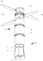
도 1은 날개깃이 확장 위치에 있는 본 발명의 한 구체예의 투시도를 도시한다.
도 2는 날개깃이 후퇴 위치에 있는 도 1의 구체예의 투시도를 도시한다.
도 3은 도 1의 구체예의 정면도를 도시한다.
도 4는 도 1의 구체예의 평면도를 도시한다.
도 5는 도 1의 구체예의 저면도를 도시한다.
도 6은 도 3의 6-6 선을 따라 절취된 도 1의 단면도를 도시한다.
도 7은 도 1의 구체예의 분해도를 도시한다.
도 8은 CPU 제어 장치의 한 구체예의 상세도를 도시한다.
도 9는 CPU 제어 장치의 다른 상세도를 도시한다.
도 10은 스니퍼 헤드(sniffer head)를 갖는 한 구체예의 투시도를 도시한다.
도 11은 도 10의 구체예의 다른 투시도를 도시한다.
도 12는 한 예시적인 스니퍼 헤드의 정면도를 도시한다.
도 13은 스니퍼 헤드의 측면도를 도시한다.
도 14는 스니퍼 헤드의 평면도를 도시한다.
도 15는 스니퍼 헤드의 저면도를 도시한다.
도 16은 스니퍼 헤드의 분해도를 도시한다.
도 17은 도 12의 17-17 선을 따라 절취된 스니퍼 헤드의 단면도를 도시한다.
도 18은 수축(contracted) 위치에 있는 조명 헤드(illumination head)를 갖는 한 구체예의 투시도를 도시한다.
도 19는 확장 위치에 있는 도 18의 구체예의 투시도를 도시한다.
도 20은 수축 위치에 있는 도 18의 구체예의 다른 투시도를 도시한다.
도 21은 확장 위치에 도 18의 구체예의 다른 투시도를 도시한다.
도 22는 조명 헤드의 정면도를 도시한다.
도 23은 조명 헤드의 측면도를 도시한다.
도 24는 조명 헤드의 평면도를 도시한다.
도 25는 조명 헤드의 저면도를 도시한다.
도 26은 조명 헤드의 분해도를 도시한다.
도 27은 조명 헤드의 단면도를 도시한다.
도 28은 전자기 펄스(EMP) 헤드를 갖는 한 구체예의 투시도를 도시한다.
도 29는 도 28의 구체예의 다른 투시도를 도시한다.
도 30은 EMP 헤드의 정면도를 도시한다.
도 31은 EMP 헤드의 측면도를 도시한다.
도 32는 EMP 헤드의 평면도를 도시한다.
도 33은 EMP 헤드의 저면도를 도시한다.
도 34는 EMP 헤드의 분해도를 도시한다.
도 35는 도 30의 35-35 선을 따라 절취된 EMP 헤드의 단면도를 도시한다.
도 36은 원격 조종 장치의 한 예시적인 구체예를 도시한다.The foregoing, and other objects, viewpoints, and advantages will be better understood from the following detailed description of embodiments of the invention that refer to the drawings, in which like numbers are used throughout the drawings to indicate the same components. Became.
1 shows a perspective view of one embodiment of the invention with the wing feathers in an extended position.
2 shows a perspective view of the embodiment of FIG. 1 with the wing feathers in the retracted position.
FIG. 3 shows a front view of the embodiment of FIG. 1.
FIG. 4 shows a top view of the embodiment of FIG. 1.
5 shows a bottom view of the embodiment of FIG. 1.
FIG. 6 shows a cross-sectional view of FIG. 1 taken along line 6-6 in FIG. 3;
FIG. 7 shows an exploded view of the embodiment of FIG. 1.
8 shows a detailed view of one specific example of the CPU control device.
Fig. 9 shows another detailed view of the CPU control device.
10 shows a perspective view of one embodiment with a sniffer head.
FIG. 11 shows another perspective view of the embodiment of FIG. 10.
12 shows a front view of an exemplary sniffer head.
13 shows a side view of the sniffer head.
14 shows a top view of the sniffer head.
15 shows a bottom view of the sniffer head.
16 shows an exploded view of the sniffer head.
FIG. 17 shows a cross-sectional view of the sniffer head taken along line 17-17 in FIG. 12.
18 shows a perspective view of one embodiment with an illumination head in a contracted position.
19 shows a perspective view of the embodiment of FIG. 18 in an extended position.
20 shows another perspective view of the embodiment of FIG. 18 in the retracted position.
21 shows another perspective view of the embodiment of FIG. 18 in an extended position.
22 shows a front view of the lighting head.
23 shows a side view of the lighting head.
24 shows a top view of the lighting head.
25 shows a bottom view of the lighting head.
26 shows an exploded view of the lighting head.
27 shows a cross-sectional view of the lighting head.
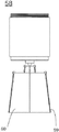
28 shows a perspective view of one embodiment with an electromagnetic pulse (EMP) head.
FIG. 29 shows another perspective view of the embodiment of FIG. 28.
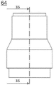
30 shows a front view of the EMP head.
31 shows a side view of the EMP head.
32 shows a top view of the EMP head.
33 shows a bottom view of the EMP head.
Fig. 34 shows an exploded view of the EMP head.
FIG. 35 shows a cross-sectional view of the EMP head taken along line 35-35 of FIG. 30.
36 shows an exemplary embodiment of a remote control device.
이제 상기 도면을 참조하여 본 발명에 따른 방법 및 구조의 예시적인 구체예를 제시한다.An exemplary embodiment of the method and structure according to the invention is now presented with reference to the drawings.
도시된 구체예의 포탄(1)은 Ascent AeroSystems, LLC가 권리를 가진 미국 특허번호 제10,093,417호에 기술된 것과 유사한, 동축 드론(coaxial drone)으로 불리는 무인 비행 장치와 페이로드를 결합한다. 다른 구체예에서는 포탄(1)이 표적으로의 전달에 적합한 무인 항공기(UAV)의 다른 디자인을 포함할 수 있다. 공중에 떠있는 항공기가 실어 나르고 그리고 발진시키는 폭발무기 또는 그러한 항공기가 실어 나르는 페이로드의 "투하(dropping)" 대신에, 포탄(1)은 현장에서 선택된 고도 및 표적 위의 위치에 도달하기 위해 비행이 조종 가능한, 내장형으로 만들어진 UAV 기능을 포함한다. 바른 위치에 있을 때, 포탄(1)은 그 전체가 표적으로 하강하도록 조종될 수 있다.The
도 1은 비행을 위해 확장된 프로펠러/로터리 날개깃(38)을 갖는 작동 중인 형태의 포탄(1)의 도면을 제공한다. 상기 폭탄은 상부 케이스(41) 및 하부 케이스(43)를 포함한다. 도 2는 날개깃(38)이 후퇴한 포탄(1)의 도면을 제공한다. 도 1 내지 도 3은 포탄(1)이 지면에 관하여 수직 방향으로 전개되었을 때, 상부 케이스(41)는 상부 케이스(41)의 제2의, 반대편의 하단의 말단부(6)의 위에 배치된 제1의, 상단의 말단부(5)를 갖는, 포탄(1)의 구성요소의 위치를 도시한다. 도 4 및 도 5는 각자 상기 폭탄의 평면도 및 저면도를 도시한다.FIG. 1 provides a view of an
도 6에 도시된 바와 같이, 상부 케이스(41)는 안에 상부 케이스(41)이 제1의, 상단의 말단부(4) 너머로 연장되는 모터 샤프트(45)를 갖는 모터(46)를 갖고, 상기 샤프트(45)는 프로펠러로도 지칭되는 로터리 날개깃(38)과 맞물리도록 결합된다. 프로펠러(38)는 기어 샤프트(37)를 통해 모터 샤프트(45)에 결합된다. 트랜시버(36) 및 안테나는 모터 샤프트(45) 위에 있는 포탄(1)의 최상단에 배치된다. 모터(46)에 동력을 공급하고 그리고 날개깃(38)을 후퇴 위치로부터 작동 위치로 이동시키고 그런 다음에 포탄(1)에 양력을 주고 조종하기 위해 추진력을 만들도록 배터리(47)는 상부 케이스(41) 안에서 모터(46) 아래에 배치되는 것으로 도시된다. 열 카메라(52)는 하부 케이스(43)의 가장 아래 위치, 열 카메라(52)가 지면을 따라 시계를 포착하는 것을 허용하는 위치에 배치된 것으로 도시된다. 마이크로프로세서 기반의 시스템(50)은 폭발물 및 열 카메라(52) 사이에 배치된다. 돔(44)은 카메라(52)를 덮을 수 있다.As shown in FIG. 6, the
도 7은 포탄(1)의 분해 투시도를 제공하고 그리고 도 8 및 도 9는 마이크로프로세서 기반의 시스템(CPU/제어 장치)(50), 착발 신관(49) 또는 충격(impact) 버튼 스위치(51)에 의해 점화되는 장약(charge), 및 열 카메라(52)를 포함하는 하부 케이스(43)의 구성요소의 상세도를 제공한다. 지면과 충돌했을 때 신관(49)을 터뜨리는 버튼 스위치(51)는 마이크로프로세서 기반의 시스템(50) 및 열 카메라(52) 사이에 위치하지만, 구성요소들의 다른 배열 및 순서도 활용될 수 있다. 마이크로프로세서 기반의 시스템(50)은 비디오 카메라(52) 및 화면 레티큘(screen reticule)을 제어하는 마이크로 컴퓨터 보드(예를 들어 lGHz 싱글 코어 CPU, 512MB RAM, Mini HDMI 및 USB 커넥터, HAT 호환가능 40핀 헤더, 컴포지트 비디오 출력, CSI 카메라 커넥터, 블루투스 및 802.11 WiFi 연결성)에 있는 것으로 도시된다. 상기 시스템은 범 지구 위치 결정 시스템(Global Position System: GPS) 정보 또한 제공한다. 한 예시로서 카메라(52)는 80x60 액티브 픽셀의 하나 이상의 초점면 배열, 증강(enhanced) IR 센서 및 50도 시계를 갖는 비냉각 열화상 장치(uncooled thermal imager)를 갖는 방사 측정 가능한 장파장 적외선(LWIR) 카메라일 수 있다. 돔(44)을 위해 선택된 소재는 적외선 영역에서 투명한 특성을 갖고, 유리하게 열화상을 위한 전면 광학부(front optic)의 역할을 하는 게르마늄 유리(germanium glass)일 수 있다. 일부 구체예에서는 돔(44)이 필요하지 않을 수 있고, 따라서 카메라 렌즈는 하부 케이스(43)로부터 돌출된다.FIG. 7 provides an exploded perspective view of the
포탄(1)은 원격으로 조종되는 비행 중 항법(in-flight navigation)에 의한 표적으로의 공수 전달(air-borne delivery)을 가능하게 한다. 항법은 지면으로부터 포탄(1)을 발진시키는 사람에 의해 실행될 수 있다. 포탄(1)에 탑재된 카메라(52)에 의해 생성된 비디오 피드(video feed)는 비디오 CCD 카메라, IR 또는 열상 카메라, 또는 다른 유형의 촬상 장치일 수 있다. 그러나 설명의 목적으로 하기의 구체예에서는 상기 촬상 장치가 열상 카메라(52)로 지칭될 수 있지만 이에 제한되지는 않는다. 열상 카메라(52)는 비행 중에 원격 조종 장치(3)에 지면의 전망을 제공할 수 있도록 포탄(1)에 배치될 수 있다. 일부 구체예에서는 표적 영역의 용이한 전망을 제공하고 그리고 아래에 있는 표적을 조준하거나 또는 그곳으로 포탄(1)의 하강을 유도하기 위해 카메라(52)가 지면을 향해 아래로 향한다.The
도 1에서 볼 수 있듯이, 포탄(1)은 비행 제어 데이터, 이미징, 페이로드 제어, 및 포탄(1)에 송신되거나 또는 그로부터 송신되는 것이 바람직한 어느 다른 데이터를 수신 및 송신하기 위한 수신기 또는 트랜시버(36)를 포함한다.As can be seen in FIG. 1, the
UAV의 기능을 제공하는 포탄(1)의 예시적인 부분은 반대쪽의 제1 말단부(5) 및 제2 말단부(6)를 갖는 축대칭 튜브형 몸체의 형태를 갖는 상부 케이스(41)를 포함한다. 일부 구체예에서 상부 케이스(41)의 제1의, 상단의 말단부(5) 및 제2의, 하단의 말단부(6)는 제1 연결기(20)로 서로에게 연결된다. 제1 연결기(20)는 하부 케이스(43)와의 상부 케이스(41)의 제거 가능한 결합 연결(mating connection)을 위한 나삿니가 있는(threaded) 부분을 포함할 수 있다. 대안적으로 연결기(20)의 기능은 죔쇠 고정(clamping), 또는 파스너 또는 제거불가(non-removable) 연결 수단을 사용하는 것으로 달성될 수 있다. 상부 케이스(41)는 ABS 튜빙으로 만들어질 수 있다.An exemplary portion of the
전개 가능 로터리 날개깃(38)은 상부 케이스(41)의 제1의, 상단의 말단부(5)에 또는 그에 근접하게 연결된다. 모터(46) 또한 상부 케이스(41)의 제1의, 상단의 말단부(5)에 배치된다. 모터(46)의 작동은 인접한 배터리 장치(47)와의 연결을 통해 동력으로 원격 조종 장치(3)에 의해 제어될 수 있다. 선택적으로 가변적인 수준(variable levels)의 전력을 생성하기 위한 원격 조종 장치(3)를 사용하여 모터(46)는 가변적인 수준의 추진력으로 날개깃(38)을 전개 및 회전시키도록 작동하는 것이 가능하다. 전개되었을 때 날개깃(38)은 지면을 따라 이동하고 그리고 포탄(1)을 표적 위치 위의 제1 고도로 가져가기 위해 추진력을 주도록 상부 케이스(41)를 중심으로 회전한다.The deployable
도 1 내지 도 9에 도시된 구체예에서는 날개깃(38)이 회전 중심축에 대해 두 개의 수직 높이에 배치되지만, 다른 공지된 날개깃 배열이 시행될 수도 있다. 날개깃(38)은 전개되었을 때 날개깃(38)이 후퇴 위치로부터 확장될 수 있게 하는, 핀(39)으로 연결된 바이어스 장치(biasing unit) 또는 스프링 장치(40)를 포함할 수 있다. 이는 포탄(1)이 사용되고 있지 않을 때 더 용이하게 운반되는 것을 허용한다.In the embodiment shown in Figs. 1 to 9, the
포탄(1)이 표적 위의 바람직한 위치에 자리잡았을 때, 원격 조종 장치(3)는 로터리 동력을 해제시켜 날개깃(38)이 회전을 중단하고 후퇴하는 것을 야기할 수 있고, 그렇게 함으로써 포탄(1)이 사실상 폭탄으로서 중력에 의해 표적을 향해 하강하는 것을 야기한다. 다른 구체예에서는 로터리 동력을 생성하는 시스템이 날개깃(38)이 후퇴하지 않고도 포탄(1)이 표적을 향해 하강하는 데 모터가 동력을 제공하도록 날개깃 회전이 반대 방향으로 작동하는 것을 허용하도록 구성될 수 있다. 요약하자면 특정 임무 및 페이로드에 따라서 상기 날개깃은 표적을 향한 포탄(1)의 더 조용하고 그리고 저저항(low drag)의 접근법을 위해 후퇴되거나, 또는 상기 날개깃은 더 큰 동력을 가지고 그리고 빠른 접근법을 위해 하향 추진으로 동력이 공급될 수 있다.When the
상기 페이로드는 폭발물(48), 화학/생물/방사선 탐지기, LED 배열과 같은 조명 장치, 전자기 펄스 장치, 또는 임무 요건에 따라 용이한 다른 페이로드일 수 있다. 예시적인 페이로드는 하부 케이스(43)에 배치될 수 있다. 하부 케이스(43)는 상이항 유형의 페이로드로 변경하는 것을 가능하게 하기 위해 모듈식이거나 제거 가능할 수 있다.The payload can be an explosive 48, a chemical / biological / radiation detector, a lighting device such as an LED array, an electromagnetic pulse device, or other payload that is easy depending on the mission requirements. The exemplary payload can be placed in the
포탄(1)의 폭발성 구성요소(48)는 원통형의 대칭적인 하부 케이스(43) 내에 있는 원통형의 형태를 가지고, 상부 케이스(41)와 대칭의 공통 축을 공유하도록 부착될 수 있다. 상부 케이스(41)의 제2의, 하단의 말단부(6) 아래에 위치한 포탄(1)의 하부 케이스(43)는 제2 연결기(11)를 통해 상부 케이스(41)에 연결된다. 제2 연결기(11)는 결합 나삿니(mating threads)를 포함하거나 또는 그의 기능이 연결기(20)에 관하여 기술된 것과 같은 다른 결합 수단으로 달성될 수 있다. 하부 케이스(43) 또한 ABS 튜빙으로 만들어질 수 있다. 도시된 배열에서, 배터리(47)는 상부 케이스(41)의 제2의, 하단의 말단부(6)에, 모터(46) 아래에 배치되고, 그리고 폭발성 구성요소(48)는 하부 케이스(43)의 상부 안에 있다.The explosive component 48 of the
도 7 내지 도 9를 참조하면, 예를 들어 마이크로프로세서 기반의 시스템을 포함하는 전자 제어 장치(50)는 하부 케이스(43)에, 폭발성 구성요소(48) 아래에 배치된다. 열상 카메라(52)는 하부 케이스(43)의 최하단부에 마이크로프로세서 기반의 시스템(50) 아래에 고정되고, 하부 케이스(43)에서 투명 돔(44)을 가진 부분 안에 있다. 돔(44)은 카메라 렌즈가 비행 중에 지면의 광각 시계를 제공하는 것을 가능하게 한다. 포탄(1)의 비행 중에 카메라(52)는 무선 주파수 링크를 통해 원격 조종 장치(3)에 디스플레이하기 위한 관심 대상의 지면의 일부 또는 지상 구조물을 영상화한다. 원격 조종 장치(3)로 포탄(1)을 조종하는 사람은 표적 위에 선택 가능한 위치로 포탄(1)을 지면을 따라 이동시킬 수 있다.Referring to FIGS. 7-9, an
마이크로프로세서 기반의 시스템(50)은 CPU 및 다른 제어 및 메모리 시스템을 포함할 수 있다. 마이크로프로세서 기반의 시스템(50)은 비행, 장애물 회피, 자동 조종, 표적 탐지, 표적 조준, 군집 능력(swarming capability), 및 컴퓨터 시스템이 실행할 수 있는 어느 다른 적합한 기능에 도움을 제공하기 위해 특정 비행 특성을 자동으로 또는 다른 방법으로 다루는 것을 허용할 수 있다.The microprocessor-based
폭발성 구성요소(48)는 착발 신관(49)(예를 들어 충돌의 힘에 의해 폭발하도록 질산 암모늄 및 알루미늄 분말과 같은 금속의 조합으로 만들어짐)으로 폭발시킬 수 있다. 착발 신관(49)은 폭발을 촉발시키기 위한 버튼/스위치(51)에도 연결될 수 있다.The explosive component 48 can explode into an outbreak fuse 49 (made, for example, from a combination of metals such as ammonium nitrate and aluminum powder to explode by impact forces). The
한 예시적인 구체예에서 착발 신관(49)의 역할을 하는 소재는 전자적으로 기폭되는 폭파용 뇌관 M6 어셈블리로 판매되고, 이는 버튼/스위치의 역할을 하는 점화약이 안에 든 알루미늄 합금 컵 또한 갖는다. 장약은 무연 화약, 염소산칼륨 및 디니트로-오르토-크레졸의 납염(lead salt), 그리고 첨장약 RDX (02NNCH2)3으로 이루어진다. 점화약에서 브릿지 와이어(스파크를 만듦)로 연결된 두 개의 도선은 이 구성에서 버튼/스위치(51)의 역할을 하는 컵의 개방부(open end)에서 고무(또는 고무 및 유황) 플러그 어셈블리를 통과하여 연장된다. 두 개의 원주 크림프(circumferential crimps)는 상기 플러그 어셈블리를 상기 컵 안에 고정시킨다. 그에 더하여 버튼/스위치(51)는 지면 또는 다른 물체와 포탄(1)의 충돌을 필요로 하지 않고서도 착발 신관(49)을 촉발시키는 것을 가능하게 하기 위한 전자 폭발 회로(electronic detonation circuit)를 포함할 수 있다. 그러한 폭발 회로는 신관(49) 및 폭발성 구성요소(48)를 폭발시키기 위해 원격 조종 장치(3)가 내보낸 명령에 응답할 것이다. 착발 신관(49)에 의해 폭발된 상기 구성요소(48)는 플라스틱 폭탄(예를 들어 C4), 또는 질산 암모늄 또는 과염소산암모늄 중 하나와 알루미늄과 같은 금속의 조합일 수 있다.In one exemplary embodiment, the material that serves as the start-up
원격 조종 장치(3)의 디자인 및 기능성은 특별히 제한되어 있지 않고 그리고 포탄(1)과 직접적으로 또는 간접적으로 통신하는 것이 가능하다. 예를 들어 상기 원격 조종 장치는 스마트폰, 단일 또는 다수의 대역폭 리모콘, 방어 시스템, 또는 어느 다른 적절한 제어의 수단일 수 있다. 도 36은 시중에서 구할 수 있는 원격 조종 장치(3)를 도시하고, 이는 카메라(52)로부터의 이미지를 보여주는 디스플레이(71), 제1 주파수(예를 들어 2.4GHz)에서 방송하는 제1 안테나(72) 및 제2 주파수(예를 들어 5.8GHz)에서 방송하는 제2 안테나(73)를 포함할 수 있다. 도시된 장치(3)는 스로틀(throttle)/방향키 제어 스틱(74) 및 승강키/에일레론 스틱(75)을 포함한다. 장치(3)는 전원 버튼(76), 시작 버튼(77), 짐벌 제어(78), 제2 디스플레이(79) 또한 포함하고, 그리고 특화된 기능을 위한 다른 다양한 제어 장치를 가질 수 있다.The design and functionality of the
포탄(1)은 적의 위치를 관찰하려고 시도할 때 시각적 노출의 위험이 한층 더 높아지는 전투 환경 또는 스나이퍼가 있을 때 용이하다. 한 예시적인 구체예에서는 동축 드론을 포함하는 포탄(1)을 배낭에 넣어 가지고 다닐 수 있고, 손에서 발진시킬 수 있고, 그리고 열상 이미지로 표적의 전망의 실시간 비디오 피드를 제공하면서 원격으로 표적 위를 비행하게 할 수 있다. 열상 이미지에서 표적을 볼 수 있고 그리고 포탄(1)이 표적 바로 위에 위치할 때, 로터리 날개깃(38)을 정지시키고 그리고 폭탄으로서 드론이 중력에 의해 표적 위로 하강하여 충돌과 함께 폭발하도록 원격 조종 장치(3)에 있는 커맨드 버튼이 활성화된다.The
민병대가 발진시켰을 때, 비행 중에 조종 가능한 포탄이 기술되었다. 이는 비행 중에 목적지의 선택을 가능하게 하고 그리고 상기 포탄을 발진시킨 사람이 상기 포탄으로부터 얻은 정보에 근거하여 복적지를 바꾸는 것을 가능하게 한다. 개시된 포탄은 상대적으로 가볍고 소형이며, 배낭에 넣어 가지고 다니기에 적합하다. 한 디자인에서는 상기 포탄의 길이가 20인치(51cm)로 제한되고 그리고 2kg의 페이로드를 적재한 상태로 30분의 비행을 위해 배터리(47)가 동력을 공급한다.When the militia launched, a maneuverable shell in flight was described. This enables the selection of a destination during the flight and enables the person who launched the shell to change the destination based on information obtained from the shell. The disclosed shell is relatively light and compact, and is suitable for carrying in a backpack. In one design, the length of the shell is limited to 20 inches (51 cm) and the
이 구체예에서 포탄(1)은 손으로 전개하는 것이 가능하다. 예를 들어 병사-작동자가 발진을 위한 로터리 날개깃(38)의 회전을 시작하기 위해 수동으로 전원을 켤 수 있고, 그런 다음 작동자는 무선 주파수(rf)로 작동되는 원격 조종 장치(3)를 통해 포탄(1)의 움직임을 조종할 수 있다. 포탄(1)이 비행 중일 때, 조작자는 상기 원격 조종 장치에 있는 모니터를 보는 것으로 상기 포탄의 지면 위의 위치를 관찰할 수 있다. 디스플레이는 포탄(1)으로부터의 실시간 피드를 근거로 한다. 조작자가 포탄(1) 아래에 표적을 봤을 때, 일부 구체예에서는 바이어스 장치 또는 스프링(21)을 통해 스프링 작동식일 수 있는 로터리 날개깃(38)을 즉시 정지시키고 그리고 접기 위해 원격 조종 장치(3)가 사용되고, 이는 포탄(1)이 선택된 표적 바로 위로 하강하는 것을 가능하게 한다. 표적의 표면과 접촉하는 순간, 부수적 피해의 최소화를 보장하면서 착발 신관(49)이 폭발물을 터뜨린다. 지면에 폭발에 의한 피해를 만드는 것을 피해야할 필요가 생길 경우, 폭발물(48)을 터뜨리기 위해 원격 조종 장치(3)가 사용될 수 있다.In this embodiment, the
본 발명은 병사가 열 레티클(thermal reticle) 및 원격 조종 디스플레이(71)를 통해 정확하게 원격으로 전달될 수 있는, 강력하고, 가벼운 탄환을 들고 다니는 것을 가능하게 한다. 포탄(1)은, 약간의 또는 전무한 부수적 피해를 수반하면서, 구조물을 통과, 예를 들어 열린 창문을 통과하게 조종될 수 있고, 그리고 샤프트 등과 같은 것을 통하여 하강하는 것이 가능하다. 포탄(1)은 지면 위로 조명을 제공하고 그리고 표적의 식별을 보장하기 위해 적외선(LED) 조명 또한 장착될 수 있다. 또한 원하는 목적지로의 이동을 가능하게 하기 위해, 작동자는 구체적인 GPS 표적 위치 및 표적 위치 위의 고도롤 지정할 수 있다. 포탄(1)은 GPS 좌표가 작동자의 고저선 밖에 있더라도 그 위치 위로 자동으로 하강하도록 프로그램될 수 있다. 포탄(1)은 무수한 신관 유형으로 작동할 수 있다. 신관 유형은 정책 및 안전 수칙 그리고 무기 호환성(arsenal compatibility)을 수용하기 위해 치환될 수 있다.The invention makes it possible for soldiers to carry powerful, lightweight bullets that can be accurately and remotely delivered via a thermal reticle and remotely controlled
도시된 구체예는 폭발 탄두 또는 다른 통상적인 그리고 통상적이지 않은 특화된 탄두로 조준선 및 조준선 너머의 지면 표적과 교전하도록 설계된 무인 동축 비행기의 한 유형인 드론 폭탄 시스템(drone bomb system)을 포함한다. 이 구체예는 지상 전투원에게 유도 또는 유도 가능한 정밀 병기를 제공하는 것이 가능한 휴대용 비행 포탄이다. 시스템에는 타게터(targeter)가 표적의 위치를 확인하하고, 표적을 감시하고, 그리고 비행체를 표적으로 유도하는 것을 가능하게 하는 고해상도의 전자광학 및/또는 적외선 카메라가 장착된다. 이 구체예의 한 이로운 특징은 습격하기 전에 장기간동안 공중에서 "비행(loiter)"하는 능력으로, 이는 타게터에게 언제 그리고 무엇을 습격할지 결정할 시간을 준다. 이 특징은 포탄이 전달되기 전에 구출(extractions)되는 것을 허용하고, 그리고 전투원이 가벼운 사고 및 지면의 상태를 보완하는 것을 허용한다. 이는 충돌 전에 다시 불러들이거나 또는 폭발시킬 수 없고, 그렇기 때문에 지상의 병력을 위험에 빠뜨릴 수 있는 통상의 미사일과 비교된다.The illustrated embodiment includes a drone bomb system, which is a type of unmanned coaxial aircraft designed to engage the sight line and ground targets beyond the sight line with explosive warheads or other conventional and unusual specialized warheads. This embodiment is a portable flight shell capable of providing guided or guided precision weapons to ground combatants. The system is equipped with a high-resolution electro-optical and / or infrared camera that enables the targeter to locate the target, monitor the target, and guide the vehicle. One beneficial feature of this embodiment is the ability to "loiter" in the air for a long period of time before attacking, which gives the target time to decide when and what to attack. This feature allows shells to be extracted before delivery, and allows combatants to compensate for minor accidents and ground conditions. This is compared to a conventional missile that cannot be recalled or exploded before a collision, and therefore puts the ground forces at risk.
갈수록 더 많은 수의 작전들이 로켓 및 박격포와 같은 통상적인 대안들에 비교하여 고유의 신규 능력 세트를 제공하는 본원에 개시된 비행 포탄의 구체예로부터 혜택을 입을 수 있다. 그러한 혜택 중 하나는 박격포, 로켓, 및 소형 미사일과 비교하여, 전투원과 비전투원을 구별하도록 강화된 능력이다. 비행 능력은 사용자가 습격 전에 장기간 동안 잠재적 표적을 탐지하고 그리고 추적하는 것을 허용한다. 이는 비적성 표적의 부수적 피해를 최소화할 수 있다.Increasingly, more operations can benefit from embodiments of the flying shell disclosed herein that provide a unique set of new capabilities compared to conventional alternatives such as rockets and mortars. One such benefit is the enhanced ability to distinguish combatants from noncombatants, compared to mortars, rockets, and small missiles. The ability to fly allows the user to detect and track potential targets for a long period of time before the raid. This can minimize the collateral damage of non-competent targets.
도시된 구체예의 또 다른 혜택은 균등한 무기와 비교하여 향상된 정밀도이다. 구체예는 예를 들어 360도 폭발을 일으키는 수류탄 보다 표적된 폭발을 더 정밀하게 만드는 전방면(forward-facing) 폭발을 일으킨다. 개시된 비행 포탄은 조종 가능하지만 다른 포탄들은 조종될 수 없다.Another benefit of the illustrated embodiment is improved precision compared to even weapons. Embodiments cause a forward-facing explosion that makes the targeted explosion more precise, for example than a grenade causing a 360-degree explosion. The disclosed flight shell is steerable, but other shells cannot.
그에 더하여 "착륙복행(wave off)" 특징은 드론 폭탄 시스템의 작동자가 비행 중에 공격을 취소하고 그리고 해를 끼치지 않고 탄환을 중단시키는 것을 허용한다. 종래의 로켓, 박격포, 및 미사일은 이 특징을 가지지 않는다. 본 발명의 일부 구체예는 드론 폭탄 시스템을 살상 물리력(deadly force)에서 비군사적이고 전략적 용도로 바꾸는 것을 허용하도록 교체 가능한 탄두 또한 제공한다. 도 10 내지 도 17에 도시된 그러한 한 예시적인 구체예는 한 영역을 비행하고 그리고 격리 구역에 진입하는 병력을 위험에 노출시키기 않도록 NBC 오염물의 존재를 검사하기 위한 공기 샘플을 획득할 수 있는 핵 생물학 및 화학(Nuclear Biological and Chemical: NBC) 스니퍼 헤드(Sniffer Head)(53)를 페이로드로서 포함할 수 있다. 도 16의 분해도를 참조하면, 스니퍼 헤드(53)는 몸체 케이스(54), 배터리(47), CPU/제어기 시스템(50), 및 소형 진공 발생 장치(mini-vacuums)(55)을 인접한 벤트(57)에 대해 바른 위치에 고정하는 것을 돕는 그리드(56)를 포함할 수 있다.In addition, the "wave off" feature allows the operator of the drone bomb system to cancel the attack in flight and stop the ammunition without harm. Conventional rockets, mortars, and missiles do not have this feature. Some embodiments of the present invention also provide a replaceable warhead to allow the drone bomb system to change from deadly force to non-military and strategic use. One such exemplary embodiment shown in FIGS. 10-17 is a nuclear biology capable of obtaining air samples for examining the presence of NBC contaminants to avoid risking personnel flying over an area and entering the containment area. And a chemical (Nuclear Biological and Chemical: NBC)
포탄(1)의 다른 예시적인 구체예는 도 18 내지 도 27에 도시되고, 이는 조명 헤드(58)를 갖는 페이로드를 도시한다. 조명 헤드(58)는 어느 유형의 조명 장치일 수 있다. 도 18 내지 도 27에 도시된 예시에서는 조명 헤드(58)가 우산형 메커니즘(59), 막(membrane) 또는 반사 커버(reflective cover)(60), 및 LED 배열/스트립(61)을 포함한다. LED 스트립(61)은 각 스트립 당 54개의 LED 조명을 갖고, 각 스트립의 길이가 36인치인 3MTM Adhesive Back을 갖는 LED 스트립 조명으로 만들어질 수 있다. 상기 스트립은 블런트 컷트(blunt cut) 연결을 제공하기 때문에 LED 3개의 길이로 절단될 수 있다. 12V 조명 스트립은 투명한 색(clear color)이거나 적색이고 그리고 방수 및 방진에 있어서 IP67 등급이다. LED는 특정한 임무에 따라 어느 색상이라도 될 수 있다. LED 스트립(61)은 야간 투시를 돕기 위해 적외선 또한 방출할 수 있다.Another exemplary embodiment of the
도 18 및 도 20에 도시된 바와 같이, 우산형 메커니즘(59)은 조명 헤드(58)를 작동시킬 때가 되기 전까지 접혀있을 수 있다. 이는 더 용이한 보관 및 운반, 더 나은 비행 특성 및 스텔스를 가능하게 한다. 도 19 및 도 21에 도시된 바와 같이, 바른 위치에 도달했을 때, 우산형 메커니즘(59)이 펼쳐져 반사 커버(60)가 펼쳐지게 하고 그리고 LED 스트립(61)을 원하는 구역(이 예시에서는 일반적으로 지면의 영역)을 밝히기 위한 위치에 배치할 수 있다. 상기의 장치는 화재를 일으킬 수 있고 "끄는(turned off)" 것이 불가능한 더 짧은 수명의 조명 박격포의 사용을 대신할 수 있다. 그에 반해서 본 발명에 따른 조명 배열은 조명 스위치처럼 필요로할 때 켜지거나 꺼질 수 있다.18 and 20, the umbrella-shaped
도 24 내지 도 27에 도시된 바와 같이, 조명 헤드(58)는 배터리(47)에 더하여 표적 구역을 더 오래 밝히기 위한 추가 배터리(63) 또한 포함할 수 있다. 조명 시스템에 더하여 다른 포탄(1) 기능도 제어하는 마이크로프로세서 기반의 제어 시스템(50') 또한 포함된다. 상기 장치(3)는 상기 시스템(50)의 기능을 제어하기 위해 사용된다.24 to 27, the
도 28 내지 도 35에 도시된 구체예는 전자 시스템을 사용 불가하게 만드는 데 유용한 전자기 펄스(EMP) 탄두(64)를 보여준다. 한 구체예에서 EMP 탄두(64)는 장치가 전신주 또는 다른 전략적 전자 표적에 착륙하고 그리고, 예를 들어 자석(64)으로 강자성 표면에 그 자체를 부착하는 것을 가능하게 하는 부착(attachment) 메커니즘을 포함한다. 그런 다음에 상기 장치는 EMP 펄스를 퍼뜨려 기반 시설에 심각한 피해를 주지 않고서 표적을 작동 불가하게 만든다. EMP 탄두(64)는 배터리(47), 마이크로프로세서 시스템(50")에 더하여 EMP 펄스를 발생시키기 위해 사용되는 구리 코일(66) 및 커패시터(67)를 포함한다. 이 구체예에서 자석(68)은 포탄(1)의 하단부에 배치되어, EMP 펄스를 퍼뜨리기 전에 그가 착륙한 곳에 부착(또는 비행 특성 및 자석의 위렵에 따라 중앙 부분에 부착)되게 한다.The embodiments shown in FIGS. 28-35 show electromagnetic pulse (EMP)
또 다른 선택은 자극물(메이스, 페퍼 스프레이)의 방출을 통한 군중 해산을 겨냥한 페이로드이다. 지상 병력은 장치를 시위 중인 군중 위로 비행시키고 그리고, 예를 들어, 특정한 그룹 바로 위에 취루 가스를 방출하는 것으로 군중이 모여있는 특정한 구역을 표적할 수 있고, 그렇게 함으로써 무고한 사람들에게 영향을 주는 것을 방지할 수 있다. 사람들을 해치거나 또는 평화 유지 병력을 향해 다시 투척될 수 있는 발사체 사용을 피하면서, 가스가 모든 군중 위로 균일하게 살포될 수도 있다.Another option is a payload aimed at disbanding the crowd through the release of irritants (mass, pepper spray). Ground troops can target specific areas of the crowd by flying the device over the protesting crowd and, for example, releasing gaseous gas directly above a specific group, thereby preventing it from affecting innocent people. Can be. Gas may be spread evenly over all crowds, avoiding the use of projectiles that can harm people or be thrown back towards a peacekeeping force.
일부 구체예에서 페이로드는 고에너지 인함유의 탄두(High-Energy Phosphorous warhead)를 포함할 수 있고, 이는, 예를 들어 자석을 통해, 탱크 또는 다른 운송 수단 또는 장비에 부착될 수 있고, 그럼 다음 금속 또는 다른 물질을 녹여버리도록(burn through) 발화되어 표적을 쓸모 없게 만든다. 예시적인 표적으로는 장갑차, 항공기 및 레이더, 장비가 있다. 조정 가능한 페이로드를 갖는 구체예에 더하여, 본 발명은 임무에 따라 다른 크기의 드론/페이로드 패키지를 포함하도록 축소 및 확장이 가능하기도 하다(scalable). 예를 들어 개시된 드론 폭탄 시스템은 축소 및 확장이 가능하고 그리고 여러(예를 들어 세 가지) 크기로 사용 가능할 수 있다. 따라서 한 구체예는 길이가 약 8인치이고 그리고 M203 수류탄과 비슷한 방식으로 파우치에 담겨 병사의 MOLE 조끼에 부착될 수 있는, 손에 들고 사용할 수 있는 크기의 소형 시스템일 수 있다. 살상 페이로드 탄두만을 포함할 수 있는 이 장치는 병사가 상기 장치를 여러 개 들고 다닐 수 있고 그리고 병사가 더 큰 위험에 절대 노출되지 않는 상태로 상기 장치를 원격으로 그의 표적으로 유도할 수 있을 만큼 소형일 수 있다. 그러한 포탄은 박격포 및 M203 유탄 발사기 유형의 시스템과 같은 오늘날 사용되는 많은 병기를 대신하거나 또는 그의 진보형일 수 있다.In some embodiments the payload can include a High-Energy Phosphorous warhead, which can be attached to a tank or other vehicle or equipment, for example through a magnet, then metal Or it ignites to burn through other materials, rendering the target useless. Exemplary targets include armored vehicles, aircraft and radar, and equipment. In addition to embodiments with adjustable payloads, the present invention is also scalable and scalable to include drone / payload packages of different sizes depending on the mission. For example, the disclosed drone bomb system is scalable and expandable and can be used in multiple (eg, three) sizes. Thus, one embodiment may be a compact system of a size that is about 8 inches long and can be held in a pouch and attached to a soldier's MOLE vest in a manner similar to an M203 grenade. The device, which can only contain a kill payload warhead, is small enough to allow a soldier to carry multiple of the device and to remotely direct the device to his target without ever being at greater risk. Can be Such shells may replace or be advanced of many of the weapons used today, such as systems of the mortar and M203 grenade launcher type systems.
다른 가능한 구체예는 교체 가능한 탄두를 가지고 그리고 길이가 약 22인치일 수 있으며, MOLLE 시스템에 고정된 튜브 안에 담겨 병사의 배낭에 고정될 수 있는 중간 크기의 시스템을 포함한다. 반면에 일부 구체예는, 예를 들어, 테러리스트 주둔지를 완전히 무너뜨릴 수 있는 위력을 가진 살상 페이로드를 지닐 수 있는 약 6피트 길이의 대형 시스템일 수 있다. 이 구체예는 군사의 자동 비행 시스템과 호환이 되고 그리고 50마일 또는 그 이상의 거리에 걸쳐 전달될 수 있다.Other possible embodiments include a medium-sized system that has a replaceable warhead and can be about 22 inches long and can be secured to a soldier's backpack in a tube secured to the MOLLE system. On the other hand, some embodiments may be, for example, a large system about 6 feet long, capable of carrying a kill payload with the power to completely destroy a terrorist station. This embodiment is compatible with military automatic flight systems and can be delivered over 50 miles or more.
개시된 드론 폭탄 시스템은 정확한 정밀도를 특징으로 하는 효과적인 페이로드 전달 시스템이기 때문에 적의 보호벽(cover)의 유용성이 완전히 무효화될 수 있다. 상기 시스템은 스나이퍼 또는 숨겨진 표적을 무력화시킬 수 있고, 그리고 어쩌면 더 중요하게는 병사가 보호벽에서 벗어나 자신을 위험에 노출시켜야 하는 필요성을 제거하는, 손에 들고 사용할 수 있는, 사람이 휴대할 수 있는 드론 폭탄의 형태를 가질 수 있다. 원격 조종 장치를 사용하여 병사는 열 이미지 처리 능력이 있는 드론 폭탄 시스템을 그의 배낭으로부터 더 안전하게 발진시킬 수 있다. 길이 22인치의 드론 폭탄 시스템의 무게는 5파운드 일 수 있고 그리고 25킬로미터의 사정거리를 가질 수 있다. 드론 폭탄 시스템의 동축 UAV 구체예가 그의 목표물 위에 도달하고 그리고 표적이 병사의 디스플레이 장치의 열 레티클에 위치할 때, 중력 또는 역추진을 사용하여 폭발물을 표적 위로 하강시킨다. 다른 무기들이 야기할 수 있는 유형의 부수적 피해를 막으면서 폭발물의 살상 페이로드가 전달된다. 드론 폭탄 시스템은 병사에게 명중 확률에 있어서 대략 500%의 향상을 제공할 수 있다.Since the disclosed drone bomb system is an effective payload delivery system characterized by precise precision, the usefulness of the enemy's cover can be completely defeated. The system is capable of neutralizing snipers or hidden targets, and perhaps more importantly, hand-held, human-portable drones that eliminate the need for soldiers to escape the barrier and put themselves at risk It can take the form of a bomb. Using a remote control, the soldier can safely launch a drone bomb system with thermal imaging capability from his backpack. A 22-inch-long drone bomb system can weigh 5 pounds and have a range of 25 kilometers. When a coaxial UAV embodiment of the drone bomb system reaches over its target and the target is placed on the thermal reticle of the soldier's display device, the explosive is lowered onto the target using gravity or back-propulsion. Explosive kill payloads are delivered, preventing the type of collateral damage that other weapons can cause. The drone bomb system can provide soldiers with an approximately 500% improvement in probability of hit.
본 발명의 예시적인 구체예가 도시되었지만 본 발명이 그에 제한되지는 않는다. 그에 따라 본 발명의 범위는 오직 청구항에 의해 한정되고, 각 청구항은 별개의 구체예를 구성한다. 구체예는 상이한 청구항들을 결합할 수 있다. 상이한 구체예들의 조합은 청구항의 범위 내에 있고 그리고 본원을 검토한 당업계의 통상의 기술자에게는 명백할 것이다.Illustrative embodiments of the invention are shown, but the invention is not limited thereto. Accordingly, the scope of the present invention is limited only by the claims, and each claim constitutes a separate embodiment. Embodiments may combine different claims. Combinations of different embodiments are within the scope of the claims and will be apparent to those skilled in the art having reviewed the present application.
Claims (20)
a. 반대쪽의 제1 말단부 및 제2 말단부를 가지고 그리고 내부에 폭발성 구성요소가 배치된 튜브형 몸체;
추진력을 주고 그리고 상기 포탄을 표적 위치 위의 제1 고도로 가져가기 위한 동력 조작(powered operation) 하에서 상기 몸체를 중심으로 회전하기 위해 제1 말단부 날개깃에 또는 그에 근접하게 상기 몸체에 연결된 복수의 날개깃;
추진력을 주고 그리고 그렇게 함으로써 상기 날개깃의 회전을 통해 상기 포탄에 추진 양력(propulsive lift)을 제공하기 위한 동력 조작을 선택적으로 제공하기 위해 연결된, 상기 몸체 내에 배치된 모터;
상기 포탄이 허공에 떠있는 동안 지면의 전망을 나타내는 이미지 데이터의 프레임을 생성하기 위해 상기 제2 말단부에 고정되고, 적외선 또는 가시 광 이미지를 습득하는 촬상 장치;
무선 주파수(rf) 제어 신호를 수신하도록 구성되고 그리고 수신된 신호에 대응하여 상기 포탄의 다른 구성요소의 작동을 달성하도록 연결된 제1 수신 회로; 및
이미지 데이터의 프레임을 수신하고 그리고 상기 이미지 데이터의 스트림을 포함하는 rf 신호를 송신하도록 연결된 rf 비디오 송신 회로를 포함하는 포탄을 제공하고;
b. 상기 포탄으로부터 멀리 배치가 가능하고,
(i) 비행 및 공중 정지 중에 사용자 입력에 대응하여 사용자가 상기 포탄의 작동을 유도하기 위한 제어 신호를 송신하는 rf 제어 회로;
(ii) 상기 이미지 데이터의 스트림을 수신하기 위한 제2 수신 회로; 및
(iii) rf 회로로부터 이미지 데이터를 수신하고 그리고 상기 이미지 데이터를 스크린에 디스플레이하는 영상 처리 회로를 포함하고,
상기 포탄이 지면 위의 공중에 떠있을 때:
(i) 상기 날개깃은 상기 모터 위에 배치되고 그리고 중심축을 기준으로한 회전을 위해 샤프트를 통해 상기 모터에 연결되고, 그리고
(ii) 상기 촬상 장치는 상기 포탄 바로 아래의 지면의 일부분의 전망을 나타내는 이미지 데이터의 프레임을 생성하도록 방향에 맞춰 배치되는;
사용자가 제어 가능한 원격 조종 장치를 제공하는 것을 포함하고,
상기 방법이:
상기 포탄에 추진 양력을 주기 위해 동력 조작을 개시하고;
상기 포탄에 배치된 촬상 장치로 습득한 이미지 데이터의 디스플레이된 프레임에 근거하여, 상기 포탄의 움직임을 표적 위치 위의 공중 위치로 조종하기 위해 상기 원격 조종 장치로부터 하나 이상의 제1 제어 신호를 보내고;
상기 포탄이 상기 표적 위치를 향해 하강하게 하도록 상기 원격 조종 장치로부터 하나 이상의 제2 신호를 보내고; 그리고
폭발성 구성요소를 폭발시키는 것을 더 포함하는 것을 특징으로 하는 방법.
A method of delivering a shell from a first altitude to a destination or above the ground and preventing collateral damage, the method comprising:
a. A tubular body having opposite first and second ends and an explosive component disposed therein;
A plurality of wing feathers connected to the body at or near the first distal wing feather to rotate about the body under a powered operation to give thrust and bring the shell to a first elevation above the target location;
A motor disposed within the body that is connected to impart propulsive force and thereby selectively provide power manipulation to provide propulsive lift to the shell through rotation of the wing;
An imaging device fixed to the second distal end to acquire an infrared or visible light image to create a frame of image data representing a view of the ground while the shell is floating in the air;
A first receiving circuit configured to receive a radio frequency (rf) control signal and coupled to achieve operation of other components of the shell in response to the received signal; And
Providing a shell comprising an rf video transmitting circuit coupled to receive a frame of image data and to transmit an rf signal comprising the stream of image data;
b. It is possible to deploy away from the shell,
(i) an rf control circuit that transmits a control signal for inducing the operation of the shell by a user in response to a user input during flight and air suspension;
(ii) a second receiving circuit for receiving the stream of image data; And
(iii) image processing circuitry for receiving image data from the rf circuit and displaying the image data on a screen,
When the shell is floating in the air above the ground:
(i) the wing feather is disposed on the motor and connected to the motor via a shaft for rotation about a central axis, and
(ii) the imaging device is arranged in orientation to produce a frame of image data representing a view of a portion of the ground just below the shell;
Providing a user controllable remote control device,
The above method:
Initiate a power operation to impart propulsion lift to the shell;
Based on a displayed frame of image data acquired by the imaging device disposed in the shell, sending one or more first control signals from the remote controller to steer the motion of the shell to an aerial position above a target position;
Send one or more second signals from the remote control device to cause the shell to descend toward the target position; And
And further comprising exploding the explosive component.
2. The method of claim 1, characterized in that it comprises a mechanism for stopping the motor operation through a task performed by the user on the remote control device so that the shell descends toward the target position at the first altitude. Way.
3. The method according to claim 2, characterized in that powered descent is achieved by transitioning from the lift or air stop mode to the descending mode by changing the direction of rotation of the wing to accelerate the descent.
The method of claim 1, wherein the step of transmitting one or more second control signals interrupts the provision of rotation of the wing, causing the shell to descend toward the target position by gravity.
The method of claim 1, wherein transmitting one or more second control signals causes the shell to air-stop just above the target location before descending to the target location.
The method of claim 1, wherein the step of exploding the explosive component is achieved by a start fuse when the shell hits the surface.
The explosive component of claim 1, further comprising a detonation switch operable to explode the explosive component, and to explode the explosive component if the user of the remote control device does not need to use the ignition fuse. If desired, the detonation step comprises activating a detonation switch with a third control signal sent from the remote control to explode the explosive component on or off the ground.
The detonation step of claim 1, further comprising a detonation switch operable to explode the explosive component, and if the explosive component does not explode upon impact, the detonation step is remote to explode the explosive component. And activating the detonation switch with a third control signal transmitted from the steering device.
The method according to claim 1, wherein the shell is deployed while the operator holds it in his hand.
10. The method of claim 9, wherein the shell is deployed by powering the shell while the operator is holding the shell and controlling the movement of the shell through the remote control device.
a. 작동자가 상기 원격 조종 장치 상의 디스플레이를 보는 것으로 지면 위의 포탄의 현위치를 관측하고;
b. 작동자가 상기 디스플레이를 통해 상기 포탄 아래에 표적이 있는 것을 확인했을 때, 작동자가 상기 원격 조종 장치를 사용하여 날개깃으로의 동력 공급을 중단하여 상기 포탄이 선택된 위치 바로 위로 하강할 수 있게 하고; 그리고
c. 표적 위치의 표면과 충돌했을 때 폭발물이 폭발하는 것을 특징으로 하는 방법.
The method of claim 10,
a. The operator observes the current position of the shell on the ground by looking at the display on the remote control device;
b. When the operator confirms through the display that there is a target under the shell, the operator uses the remote control to stop supplying power to the wing, allowing the shell to descend directly above the selected position; And
c. A method characterized in that an explosive explodes when colliding with a surface at a target location.
The method according to claim 1, characterized in that the shell descends from the first altitude toward the target position in a direction perpendicular to the ground.
The method of claim 1, characterized in that the wing manipulator in a folded or retracted position is deployed in an extended position to provide rotation and lift.
15. The method of claim 13, wherein the wing feather is spring operated to achieve deployment to an extended position.
전개되었을 때 추진력을 주고 그리고 포탄을 표적 위치 위의 제1 고도로 가져가기 위해 상기 튜브형 몸체를 중심으로 회전 가능하고, 상기 제1 말단부에 또는 그에 근접하게 상기 몸체에 연결된 복수의 전개 가능한 날개깃;
상기 튜브형 몸체에 부착되고 그리고 상기 날개깃이 전개된 후 상기 날개깃을 회전시키기 위해 선택적으로 동력을 공급하기 위해 연결된 모터;
상기 포탄을 제1 고도로부터 표적으로 하강시키기 위해 연결된 스위치; 및
상기 포탄으로부터 지면의 일부분의 전망을 생성하도록 배치된 카메라를 포함하고;
상기 포탄이 전개되었을 때 상기 포탄을 표적 위의 위치로 조종하고 그리고 표적으로 상기 포탄을 하강시키기 위해 상기 포탄의 비행이 원격 조종 장치로 조종 가능한 것을 특징으로 하는 지면 위에서의 이동을 위한 포탄.
A tubular body having opposite first and second ends;
A plurality of deployable wing feathers rotatable about the tubular body and connected to the body at or near the first distal end to provide thrust when deployed and take the shell to a first elevation above the target location;
A motor attached to the tubular body and connected to selectively supply power to rotate the blade after the blade is deployed;
A switch connected to lower the shell from a first altitude to a target; And
A camera arranged to generate a view of a portion of the ground from the shell;
A shell for movement on the ground, characterized in that the flight of the shell can be controlled by a remote control device to steer the shell to a position above the target when the shell is deployed and to lower the shell to a target.
포탄의 조종 그리고 모터 및 카메라의 작동을 포함하는 포탄의 작동, 그리고 조종을 위한 날개깃의 조정을 제어하기 위해 작동 가능하게 연결된 마이크로프로세서 기반의 서브시스템; 및
원격 조종 장치를 더 포함하고;
상기 원격 조종 장치가 상기 포탄을 제1 고도로부터 하강시키는 스위치의 기능을 포함하여 상기 포탄의 작동의 조종을 달성하기 위하여 rf 링크를 통해 상기 마이크로프로세서 기반의 서브시스템에 데이터를 송신할 수 있고 그리고 그로부터 데이터를 수신할 수 있는 것을 특징으로 하는 시스템.
A system comprising the shell of claim 15:
A microprocessor-based subsystem operatively connected to control the operation of the shell, including the operation of the shell and the operation of the motor and camera, and the adjustment of the wing for steering; And
Further comprising a remote control device;
The remote control device can transmit data to and from the microprocessor based subsystem via an rf link to achieve control of the operation of the shell, including the function of a switch to lower the shell from a first altitude. A system characterized by being capable of receiving data.
상기 상부 케이스의 하단에 연결된 하부 케이스;
전개되었을 때 추진력을 주고 그리고 포탄을 표적 위치 위의 제1 고도로 가져가기 위해 상기 상부 케이스를 중심으로 회전 가능하게 상기 상부 케이스에 연결된 복수의 전개 가능한 동축 날개깃;
상기 상부 케이스에 부착되고 그리고 수직 이륙 및 비행이 가능하도록 상기 날개깃을 회전시키기 위해 선택적으로 동력을 공급하도록 연결된 모터;
상기 하부 케이스에 부착된 페이로드(payload); 및
상기 하부 케이스에 부착되고 그리고 상기 포탄으로부터 지면의 적어도 일부분의 전망을 생성하도록 배치된 이미징 시스템을 포함하는 것을 특징으로 하는 지면 위에서의 이동을 위한 포탄.
Upper case;
A lower case connected to a lower end of the upper case;
A plurality of deployable coaxial wing feathers rotatably connected to the upper case around the upper case to give propulsion when deployed and take the shell to a first elevation above the target location;
A motor attached to the upper case and connected to selectively power to rotate the wing feather to enable vertical takeoff and flight;
A payload attached to the lower case; And
And an imaging system attached to the lower case and arranged to create a view of at least a portion of the ground from the shell.
17. The method of claim 16, further comprising a receiver configured to receive a remote signal such that the flight of the shell is steerable through a remote signal to steer the shell to a position above a target position when the shell is deployed. Shells for movement on the ground.
19. A shell for movement on the ground according to claim 18, characterized in that the blade is configured to retract when rotation of the blade is stopped.
Applications Claiming Priority (5)
| Application Number | Priority Date | Filing Date | Title |
|---|---|---|---|
| US201762568518P | 2017-10-05 | 2017-10-05 | |
| US62/568,518 | 2017-10-05 | ||
| US201862726976P | 2018-09-04 | 2018-09-04 | |
| US62/726,976 | 2018-09-04 | ||
| PCT/US2018/054767 WO2019177664A1 (en) | 2017-10-05 | 2018-10-05 | Remotely controllable aeronautical ordnance |
Publications (2)
| Publication Number | Publication Date |
|---|---|
| KR20200057777A true KR20200057777A (en) | 2020-05-26 |
| KR102684429B1 KR102684429B1 (en) | 2024-07-11 |
Family
ID=65993095
Family Applications (1)
| Application Number | Title | Priority Date | Filing Date |
|---|---|---|---|
| KR1020207012796A Active KR102684429B1 (en) | 2017-10-05 | 2018-10-05 | remotely controlled aerial artillery shell |
Country Status (17)
| Country | Link |
|---|---|
| US (2) | US11067374B2 (en) |
| EP (1) | EP3691969A4 (en) |
| JP (1) | JP7237070B2 (en) |
| KR (1) | KR102684429B1 (en) |
| CN (1) | CN111770881A (en) |
| AU (3) | AU2018413298B2 (en) |
| BR (1) | BR112020006858A2 (en) |
| IL (1) | IL273660B (en) |
| JO (1) | JOP20200084A1 (en) |
| MX (1) | MX2020004357A (en) |
| PH (1) | PH12020550165A1 (en) |
| RU (1) | RU2020115187A (en) |
| SA (1) | SA520411690B1 (en) |
| SG (1) | SG11202003095TA (en) |
| UA (1) | UA127762C2 (en) |
| WO (1) | WO2019177664A1 (en) |
| ZA (2) | ZA202002331B (en) |
Cited By (4)
| Publication number | Priority date | Publication date | Assignee | Title |
|---|---|---|---|---|
| KR102312650B1 (en) * | 2020-06-17 | 2021-10-13 | 주식회사 한화 | Free-fall warhead with precession motion control |
| KR20220154301A (en) * | 2021-05-12 | 2022-11-22 | 주식회사 에아가이아 | Portable dron bomb device for military |
| KR20240138702A (en) | 2023-03-13 | 2024-09-20 | 주식회사 플러스인 | Educational drone equipped with a means of dropping |
| KR102711114B1 (en) * | 2024-02-05 | 2024-09-27 | 주식회사 호운 | Launch and Recovery Vehicle for Reconnaissance Drones |
Families Citing this family (28)
| Publication number | Priority date | Publication date | Assignee | Title |
|---|---|---|---|---|
| KR101917785B1 (en) * | 2016-10-26 | 2019-01-29 | 한국항공우주연구원 | Non-motorized type flying unit for observation |
| US12031802B2 (en) | 2017-07-26 | 2024-07-09 | Northrop Grumman Systems Corporation | Despun wing control system for guided projectile maneuvers |
| CN111770881A (en) * | 2017-10-05 | 2020-10-13 | 欧弗沃克斯有限公司 | Remote Controlled Aviation Ordnance |
| US11578956B1 (en) * | 2017-11-01 | 2023-02-14 | Northrop Grumman Systems Corporation | Detecting body spin on a projectile |
| CN108298064B (en) * | 2017-11-09 | 2024-04-26 | 青岛兰道尔空气动力工程有限公司 | Unconventional yaw control system |
| GB2586843B (en) * | 2019-09-05 | 2023-03-29 | Bae Systems Plc | Improvements in and relating to a guided weapon |
| GB2586854B (en) * | 2019-09-06 | 2023-05-17 | Bae Systems Plc | Improvements in and relating to weapon control |
| KR102444099B1 (en) * | 2019-12-10 | 2022-09-15 | 주식회사 한화 | Electronic detonator device with dual antenna for blasting system and blasting system using the same |
| CN111099018B (en) * | 2019-12-26 | 2021-10-22 | 浙江海洋大学 | Material delivery device and control method for maritime unmanned aerial vehicle |
| CN111156865A (en) * | 2020-01-07 | 2020-05-15 | 北京理工大学 | Coaxial multi-rotor patrol missile |
| KR102330716B1 (en) * | 2020-06-30 | 2021-11-25 | 주식회사 풍산 | Diving Drone Assembly |
| IL275792B (en) * | 2020-07-01 | 2021-08-31 | Imi Systems Ltd | Incoming aerial threat protection system and method |
| RU2769180C1 (en) * | 2021-04-22 | 2022-03-29 | Акционерное общество "Государственное научно-производственное предприятие "Регион" | Aerodynamic layout of a controlled gliding aerial bomb |
| CN113085462B (en) * | 2021-04-23 | 2023-06-13 | 南京航空航天大学 | A cross-media unmanned aerial vehicle device and its control method |
| WO2023027817A2 (en) * | 2021-07-09 | 2023-03-02 | Cheytac Usa Inc. | Advanced projectile with removable tips |
| US11650036B2 (en) | 2021-07-12 | 2023-05-16 | Ensign-Bickford Aerospace & Defense Company | Payload platform for unmanned vehicles |
| CN113847850B (en) * | 2021-08-30 | 2023-03-24 | 西安近代化学研究所 | War inducing device for realizing mechanical transmission by utilizing wind resistance to transmit power |
| CN114322675A (en) * | 2021-11-30 | 2022-04-12 | 上海机电工程研究所 | Deformable ejector rod and foldable control surface structure in foldable rudder of guided missile and guided missile |
| US12313389B1 (en) | 2022-03-11 | 2025-05-27 | Northrop Grumman Systems Corporation | Tunable safe and arming devices and methods of manufacture |
| JP2023178936A (en) * | 2022-06-06 | 2023-12-18 | 和浩 山本 | Fall trajectory control system |
| PL441807A1 (en) * | 2022-07-21 | 2024-01-22 | Filipek-Motors Spółka Z Ograniczoną Odpowiedzialnością | Foldable drone |
| CN115056984A (en) * | 2022-07-25 | 2022-09-16 | 哈尔滨工业大学 | Microminiature load dispenser and dispensing method |
| US12623781B1 (en) | 2022-12-15 | 2026-05-12 | CaptureTec LLC | Payload container for unmanned aircraft and associated systems and methods |
| USD1078914S1 (en) * | 2022-12-15 | 2025-06-10 | CaptureTec LLC | Payload container |
| US12630317B1 (en) * | 2023-09-11 | 2026-05-19 | Battle Sight Technologies, LLC | Elevated autonomous rescue signal antenna |
| KR102826675B1 (en) * | 2023-09-18 | 2025-06-27 | 태경전자주식회사 | Drone that provides lighting function |
| CN118124838B (en) * | 2024-05-08 | 2024-07-16 | 杭州而墨农业技术有限公司 | Seedling condition and pest and disease damage early warning patrol unmanned aerial vehicle and method |
| US12662244B1 (en) | 2024-12-20 | 2026-06-23 | Lockheed Martin Corporation | Double hinged tilting mount for coaxial contra rotating electric propulsion |
Citations (2)
| Publication number | Priority date | Publication date | Assignee | Title |
|---|---|---|---|---|
| US20050051667A1 (en) * | 2001-12-21 | 2005-03-10 | Arlton Paul E. | Micro-rotorcraft surveillance system |
| KR20170091263A (en) * | 2016-01-31 | 2017-08-09 | 자이로캠주식회사 | The drone with camera sensor and bomb for suicide bombing, and the remote control and monitoring device |
Family Cites Families (20)
| Publication number | Priority date | Publication date | Assignee | Title |
|---|---|---|---|---|
| US5657947A (en) * | 1994-08-24 | 1997-08-19 | Loral Corp. | Precision guidance system for aircraft launched bombs |
| JP2000266499A (en) | 1999-03-16 | 2000-09-29 | Toshiba Corp | Anti-aircraft defense device |
| CN2416481Y (en) * | 2000-04-07 | 2001-01-24 | 李国红 | Shell for striking airplane and air paraboy |
| ES2504167T3 (en) | 2004-04-14 | 2014-10-08 | Paul E. Arlton | Rotating wings vehicle |
| US9434471B2 (en) * | 2005-04-14 | 2016-09-06 | Paul E Arlton | Rotary wing vehicle |
| US8314374B2 (en) * | 2005-06-20 | 2012-11-20 | Aurora Flight Sciences Corporation | Remotely-guided vertical take-off system and method for delivering an ordnance to a target |
| US7854410B2 (en) * | 2006-05-15 | 2010-12-21 | Kazak Composites, Incorporated | Powered unmanned aerial vehicle |
| US7581702B2 (en) * | 2006-06-09 | 2009-09-01 | Insitu, Inc. | Wirelessly controlling unmanned aircraft and accessing associated surveillance data |
| US8328130B2 (en) * | 2008-12-08 | 2012-12-11 | Honeywell International Inc. | Vertical take off and landing unmanned aerial vehicle airframe structure |
| KR101730664B1 (en) | 2009-02-02 | 2017-04-26 | 에어로바이론먼트, 인크. | Multimode unmanned aerial vehicle |
| DK3133019T3 (en) * | 2009-09-09 | 2019-02-18 | Aerovironment Inc | NOISE DEVICE FOR A DRONE PROTECTION PIPE |
| US9308799B2 (en) * | 2011-03-29 | 2016-04-12 | Denso International America, Inc. | Variable evaporator outlet air pressure distribution |
| US8985025B1 (en) * | 2011-12-06 | 2015-03-24 | The United States Of America As Represented By The Secretary Of The Army | Submunition and cluster munition containing submunitions |
| US9194678B2 (en) * | 2012-04-25 | 2015-11-24 | Wilcox Industries Corp. | Modular rocket system |
| KR20150001821U (en) | 2013-11-05 | 2015-05-13 | 정선화 | Pan Tilt explosion and dust ignition proof camera with both side camera housing |
| WO2016077278A1 (en) | 2014-11-10 | 2016-05-19 | Ascent Aerosystems Llc | Unmanned flying device |
| WO2017040254A1 (en) * | 2015-08-28 | 2017-03-09 | Laufer Wind Group Llc | Mitigation of small unmanned aircraft systems threats |
| US10655936B2 (en) * | 2016-10-28 | 2020-05-19 | Rosemount Aerospace Inc. | Coordinating multiple missile targeting via optical inter-missile communications |
| US10287010B2 (en) * | 2016-11-02 | 2019-05-14 | Bell Helicopter Textron Inc. | Rotor sequencing for dual rotor aircraft |
| CN111770881A (en) * | 2017-10-05 | 2020-10-13 | 欧弗沃克斯有限公司 | Remote Controlled Aviation Ordnance |
-
2018
- 2018-10-05 CN CN201880064739.5A patent/CN111770881A/en active Pending
- 2018-10-05 UA UAA202002672A patent/UA127762C2/en unknown
- 2018-10-05 SG SG11202003095TA patent/SG11202003095TA/en unknown
- 2018-10-05 AU AU2018413298A patent/AU2018413298B2/en active Active
- 2018-10-05 JP JP2020520028A patent/JP7237070B2/en active Active
- 2018-10-05 MX MX2020004357A patent/MX2020004357A/en unknown
- 2018-10-05 KR KR1020207012796A patent/KR102684429B1/en active Active
- 2018-10-05 BR BR112020006858-6A patent/BR112020006858A2/en not_active Application Discontinuation
- 2018-10-05 JO JOP/2020/0084A patent/JOP20200084A1/en unknown
- 2018-10-05 WO PCT/US2018/054767 patent/WO2019177664A1/en not_active Ceased
- 2018-10-05 RU RU2020115187A patent/RU2020115187A/en unknown
- 2018-10-05 US US16/153,696 patent/US11067374B2/en active Active
- 2018-10-05 EP EP18909554.0A patent/EP3691969A4/en active Pending
-
2020
- 2020-03-27 IL IL273660A patent/IL273660B/en unknown
- 2020-03-27 PH PH12020550165A patent/PH12020550165A1/en unknown
- 2020-03-30 AU AU2020100488A patent/AU2020100488A4/en not_active Ceased
- 2020-04-02 SA SA520411690A patent/SA520411690B1/en unknown
- 2020-05-04 ZA ZA2020/02331A patent/ZA202002331B/en unknown
-
2021
- 2021-07-19 US US17/378,765 patent/US11940251B2/en active Active
-
2022
- 2022-01-27 ZA ZA2022/01297A patent/ZA202201297B/en unknown
- 2022-10-14 AU AU2022252842A patent/AU2022252842A1/en not_active Abandoned
Patent Citations (2)
| Publication number | Priority date | Publication date | Assignee | Title |
|---|---|---|---|---|
| US20050051667A1 (en) * | 2001-12-21 | 2005-03-10 | Arlton Paul E. | Micro-rotorcraft surveillance system |
| KR20170091263A (en) * | 2016-01-31 | 2017-08-09 | 자이로캠주식회사 | The drone with camera sensor and bomb for suicide bombing, and the remote control and monitoring device |
Cited By (4)
| Publication number | Priority date | Publication date | Assignee | Title |
|---|---|---|---|---|
| KR102312650B1 (en) * | 2020-06-17 | 2021-10-13 | 주식회사 한화 | Free-fall warhead with precession motion control |
| KR20220154301A (en) * | 2021-05-12 | 2022-11-22 | 주식회사 에아가이아 | Portable dron bomb device for military |
| KR20240138702A (en) | 2023-03-13 | 2024-09-20 | 주식회사 플러스인 | Educational drone equipped with a means of dropping |
| KR102711114B1 (en) * | 2024-02-05 | 2024-09-27 | 주식회사 호운 | Launch and Recovery Vehicle for Reconnaissance Drones |
Also Published As
| Publication number | Publication date |
|---|---|
| SG11202003095TA (en) | 2020-05-28 |
| ZA202201297B (en) | 2024-03-27 |
| ZA202002331B (en) | 2023-01-25 |
| KR102684429B1 (en) | 2024-07-11 |
| JP7237070B2 (en) | 2023-03-10 |
| US11067374B2 (en) | 2021-07-20 |
| AU2018413298A1 (en) | 2020-04-16 |
| BR112020006858A2 (en) | 2020-10-06 |
| AU2020100488A4 (en) | 2020-05-14 |
| RU2020115187A (en) | 2021-11-09 |
| CA3078211A1 (en) | 2019-09-19 |
| SA520411690B1 (en) | 2022-07-03 |
| JOP20200084A1 (en) | 2020-04-30 |
| IL273660B (en) | 2022-02-01 |
| JP2020537736A (en) | 2020-12-24 |
| IL273660A (en) | 2020-05-31 |
| NZ764177A (en) | 2025-09-26 |
| US20190107374A1 (en) | 2019-04-11 |
| RU2020115187A3 (en) | 2021-12-20 |
| EP3691969A4 (en) | 2020-11-11 |
| AU2018413298B2 (en) | 2022-07-14 |
| PH12020550165A1 (en) | 2021-02-22 |
| AU2022252842A1 (en) | 2022-11-10 |
| MX2020004357A (en) | 2020-10-05 |
| UA127762C2 (en) | 2023-12-27 |
| WO2019177664A1 (en) | 2019-09-19 |
| US11940251B2 (en) | 2024-03-26 |
| US20220163304A1 (en) | 2022-05-26 |
| CN111770881A (en) | 2020-10-13 |
| EP3691969A1 (en) | 2020-08-12 |
Similar Documents
| Publication | Publication Date | Title |
|---|---|---|
| US11940251B2 (en) | Remotely controllable aeronautical ordnance | |
| JP7195415B2 (en) | A counter-deployment system that facilitates the neutralization of the target aircraft | |
| US11753160B2 (en) | Unmanned aerial vehicle | |
| US8648285B2 (en) | Remotely guided gun-fired and mortar rounds | |
| US20220170725A1 (en) | Visual guidance system for barrel-fired projectiles | |
| US9019375B1 (en) | Target locator and interceptor imaging and sensing assembly, system and method | |
| KR101188294B1 (en) | Unmanned aerial vehicle for electronic warfare which uses jet engine | |
| ES2452068T3 (en) | Guided weapon with multiple fuse modes switchable in flight | |
| US20160138893A1 (en) | Remotely guided gun-fired and mortar rounds | |
| WO2013102750A1 (en) | Surveillance system | |
| US8314374B2 (en) | Remotely-guided vertical take-off system and method for delivering an ordnance to a target | |
| KR102483718B1 (en) | Portable dron bomb device for military | |
| RU2558528C1 (en) | Drone strike complex | |
| RU2681826C2 (en) | Unmanned missile strike system | |
| US20050062638A1 (en) | Missile deflector for airplanes | |
| CN103471472A (en) | Aerial anti-terrorist unit for firing mini-rocket to propel special ammunition | |
| RU2514324C1 (en) | Portable surface-to-air missile system /versions/ | |
| KR102692251B1 (en) | Stray Bullet Ground Drop Apparatus for Small Drone | |
| CA3078211C (en) | Remotely controllable aeronautical ordnance | |
| JP5547435B2 (en) | Landing observation system | |
| RU233813U1 (en) | A destructive device for dropping from an unmanned aerial vehicle | |
| AU2017228525A1 (en) | Unmanned aerial vehicle |
Legal Events
| Date | Code | Title | Description |
|---|---|---|---|
| PA0105 | International application |
Patent event date: 20200504 Patent event code: PA01051R01D Comment text: International Patent Application |
|
| PG1501 | Laying open of application | ||
| A201 | Request for examination | ||
| PA0201 | Request for examination |
Patent event code: PA02012R01D Patent event date: 20211001 Comment text: Request for Examination of Application |
|
| E902 | Notification of reason for refusal | ||
| PE0902 | Notice of grounds for rejection |
Comment text: Notification of reason for refusal Patent event date: 20230911 Patent event code: PE09021S01D |
|
| E701 | Decision to grant or registration of patent right | ||
| PE0701 | Decision of registration |
Patent event code: PE07011S01D Comment text: Decision to Grant Registration Patent event date: 20240424 |
|
| GRNT | Written decision to grant | ||
| PR0701 | Registration of establishment |
Comment text: Registration of Establishment Patent event date: 20240709 Patent event code: PR07011E01D |
|
| PR1002 | Payment of registration fee |
Payment date: 20240709 End annual number: 3 Start annual number: 1 |
|
| PG1601 | Publication of registration |