KR20200059778A - Sterilizing electrode and method thereof and sterilizer using same - Google Patents
Sterilizing electrode and method thereof and sterilizer using same Download PDFInfo
- Publication number
- KR20200059778A KR20200059778A KR1020180144912A KR20180144912A KR20200059778A KR 20200059778 A KR20200059778 A KR 20200059778A KR 1020180144912 A KR1020180144912 A KR 1020180144912A KR 20180144912 A KR20180144912 A KR 20180144912A KR 20200059778 A KR20200059778 A KR 20200059778A
- Authority
- KR
- South Korea
- Prior art keywords
- electrode
- sterilizing
- platinum
- insulator
- conductor
- Prior art date
- Legal status (The legal status is an assumption and is not a legal conclusion. Google has not performed a legal analysis and makes no representation as to the accuracy of the status listed.)
- Granted
Links
Images






Classifications
-
- C—CHEMISTRY; METALLURGY
- C02—TREATMENT OF WATER, WASTE WATER, SEWAGE, OR SLUDGE
- C02F—TREATMENT OF WATER, WASTE WATER, SEWAGE, OR SLUDGE
- C02F1/00—Treatment of water, waste water, or sewage
- C02F1/46—Treatment of water, waste water, or sewage by electrochemical methods
- C02F1/461—Treatment of water, waste water, or sewage by electrochemical methods by electrolysis
- C02F1/46104—Devices therefor; Their operating or servicing
- C02F1/46109—Electrodes
-
- A—HUMAN NECESSITIES
- A01—AGRICULTURE; FORESTRY; ANIMAL HUSBANDRY; HUNTING; TRAPPING; FISHING
- A01K—ANIMAL HUSBANDRY; AVICULTURE; APICULTURE; PISCICULTURE; FISHING; REARING OR BREEDING ANIMALS, NOT OTHERWISE PROVIDED FOR; NEW BREEDS OF ANIMALS
- A01K1/00—Housing animals; Equipment therefor
-
- A—HUMAN NECESSITIES
- A01—AGRICULTURE; FORESTRY; ANIMAL HUSBANDRY; HUNTING; TRAPPING; FISHING
- A01K—ANIMAL HUSBANDRY; AVICULTURE; APICULTURE; PISCICULTURE; FISHING; REARING OR BREEDING ANIMALS, NOT OTHERWISE PROVIDED FOR; NEW BREEDS OF ANIMALS
- A01K13/00—Devices for grooming or caring of animals, e.g. curry-combs; Fetlock rings; Tail-holders; Devices for preventing crib-biting; Washing devices; Protection against weather conditions or insects
- A01K13/001—Washing, cleaning, or drying devices
-
- A—HUMAN NECESSITIES
- A61—MEDICAL OR VETERINARY SCIENCE; HYGIENE
- A61L—METHODS OR APPARATUS FOR STERILISING MATERIALS OR OBJECTS IN GENERAL; DISINFECTION, STERILISATION OR DEODORISATION OF AIR; CHEMICAL ASPECTS OF BANDAGES, DRESSINGS, ABSORBENT PADS OR SURGICAL ARTICLES; MATERIALS FOR BANDAGES, DRESSINGS, ABSORBENT PADS OR SURGICAL ARTICLES
- A61L2/00—Disinfection or sterilisation of materials or objects, in general; Accessories therefor
- A61L2/02—Disinfection or sterilisation of materials or objects, in general; Accessories therefor using physical processes
- A61L2/03—Electric current
-
- A—HUMAN NECESSITIES
- A61—MEDICAL OR VETERINARY SCIENCE; HYGIENE
- A61L—METHODS OR APPARATUS FOR STERILISING MATERIALS OR OBJECTS IN GENERAL; DISINFECTION, STERILISATION OR DEODORISATION OF AIR; CHEMICAL ASPECTS OF BANDAGES, DRESSINGS, ABSORBENT PADS OR SURGICAL ARTICLES; MATERIALS FOR BANDAGES, DRESSINGS, ABSORBENT PADS OR SURGICAL ARTICLES
- A61L2/00—Disinfection or sterilisation of materials or objects, in general; Accessories therefor
- A61L2/16—Disinfection or sterilisation of materials or objects, in general; Accessories therefor using chemical substances
- A61L2/18—Liquid substances
-
- A—HUMAN NECESSITIES
- A61—MEDICAL OR VETERINARY SCIENCE; HYGIENE
- A61L—METHODS OR APPARATUS FOR STERILISING MATERIALS OR OBJECTS IN GENERAL; DISINFECTION, STERILISATION OR DEODORISATION OF AIR; CHEMICAL ASPECTS OF BANDAGES, DRESSINGS, ABSORBENT PADS OR SURGICAL ARTICLES; MATERIALS FOR BANDAGES, DRESSINGS, ABSORBENT PADS OR SURGICAL ARTICLES
- A61L2/00—Disinfection or sterilisation of materials or objects, in general; Accessories therefor
- A61L2/16—Disinfection or sterilisation of materials or objects, in general; Accessories therefor using chemical substances
- A61L2/22—Phase substances, e.g. smokes or aerosols
-
- C—CHEMISTRY; METALLURGY
- C02—TREATMENT OF WATER, WASTE WATER, SEWAGE, OR SLUDGE
- C02F—TREATMENT OF WATER, WASTE WATER, SEWAGE, OR SLUDGE
- C02F1/00—Treatment of water, waste water, or sewage
- C02F1/46—Treatment of water, waste water, or sewage by electrochemical methods
- C02F1/461—Treatment of water, waste water, or sewage by electrochemical methods by electrolysis
- C02F1/467—Treatment of water, waste water, or sewage by electrochemical methods by electrolysis by electrochemical disinfection; by electrooxydation or by electroreduction
- C02F1/4672—Treatment of water, waste water, or sewage by electrochemical methods by electrolysis by electrochemical disinfection; by electrooxydation or by electroreduction by electrooxydation
- C02F1/4674—Treatment of water, waste water, or sewage by electrochemical methods by electrolysis by electrochemical disinfection; by electrooxydation or by electroreduction by electrooxydation with halogen or compound of halogens, e.g. chlorine, bromine
-
- A—HUMAN NECESSITIES
- A61—MEDICAL OR VETERINARY SCIENCE; HYGIENE
- A61L—METHODS OR APPARATUS FOR STERILISING MATERIALS OR OBJECTS IN GENERAL; DISINFECTION, STERILISATION OR DEODORISATION OF AIR; CHEMICAL ASPECTS OF BANDAGES, DRESSINGS, ABSORBENT PADS OR SURGICAL ARTICLES; MATERIALS FOR BANDAGES, DRESSINGS, ABSORBENT PADS OR SURGICAL ARTICLES
- A61L2103/00—Materials or objects being the target of disinfection or sterilisation
- A61L2103/75—Room floors or walls
-
- A—HUMAN NECESSITIES
- A61—MEDICAL OR VETERINARY SCIENCE; HYGIENE
- A61L—METHODS OR APPARATUS FOR STERILISING MATERIALS OR OBJECTS IN GENERAL; DISINFECTION, STERILISATION OR DEODORISATION OF AIR; CHEMICAL ASPECTS OF BANDAGES, DRESSINGS, ABSORBENT PADS OR SURGICAL ARTICLES; MATERIALS FOR BANDAGES, DRESSINGS, ABSORBENT PADS OR SURGICAL ARTICLES
- A61L2202/00—Aspects relating to methods or apparatus for disinfecting or sterilising materials or objects
- A61L2202/10—Apparatus features
- A61L2202/11—Apparatus for generating biocidal substances, e.g. vaporisers, UV lamps
-
- A—HUMAN NECESSITIES
- A61—MEDICAL OR VETERINARY SCIENCE; HYGIENE
- A61L—METHODS OR APPARATUS FOR STERILISING MATERIALS OR OBJECTS IN GENERAL; DISINFECTION, STERILISATION OR DEODORISATION OF AIR; CHEMICAL ASPECTS OF BANDAGES, DRESSINGS, ABSORBENT PADS OR SURGICAL ARTICLES; MATERIALS FOR BANDAGES, DRESSINGS, ABSORBENT PADS OR SURGICAL ARTICLES
- A61L2202/00—Aspects relating to methods or apparatus for disinfecting or sterilising materials or objects
- A61L2202/10—Apparatus features
- A61L2202/15—Biocide distribution means, e.g. nozzles, pumps, manifolds, fans, baffles, sprayers
-
- C—CHEMISTRY; METALLURGY
- C02—TREATMENT OF WATER, WASTE WATER, SEWAGE, OR SLUDGE
- C02F—TREATMENT OF WATER, WASTE WATER, SEWAGE, OR SLUDGE
- C02F1/00—Treatment of water, waste water, or sewage
- C02F1/46—Treatment of water, waste water, or sewage by electrochemical methods
- C02F1/461—Treatment of water, waste water, or sewage by electrochemical methods by electrolysis
- C02F1/46104—Devices therefor; Their operating or servicing
- C02F1/46109—Electrodes
- C02F2001/46133—Electrodes characterised by the material
-
- C—CHEMISTRY; METALLURGY
- C02—TREATMENT OF WATER, WASTE WATER, SEWAGE, OR SLUDGE
- C02F—TREATMENT OF WATER, WASTE WATER, SEWAGE, OR SLUDGE
- C02F1/00—Treatment of water, waste water, or sewage
- C02F1/46—Treatment of water, waste water, or sewage by electrochemical methods
- C02F1/461—Treatment of water, waste water, or sewage by electrochemical methods by electrolysis
- C02F1/46104—Devices therefor; Their operating or servicing
- C02F1/46109—Electrodes
- C02F2001/46133—Electrodes characterised by the material
- C02F2001/46138—Electrodes comprising a substrate and a coating
- C02F2001/46142—Catalytic coating
-
- C—CHEMISTRY; METALLURGY
- C02—TREATMENT OF WATER, WASTE WATER, SEWAGE, OR SLUDGE
- C02F—TREATMENT OF WATER, WASTE WATER, SEWAGE, OR SLUDGE
- C02F1/00—Treatment of water, waste water, or sewage
- C02F1/46—Treatment of water, waste water, or sewage by electrochemical methods
- C02F1/461—Treatment of water, waste water, or sewage by electrochemical methods by electrolysis
- C02F1/46104—Devices therefor; Their operating or servicing
- C02F1/46109—Electrodes
- C02F2001/46152—Electrodes characterised by the shape or form
-
- C—CHEMISTRY; METALLURGY
- C02—TREATMENT OF WATER, WASTE WATER, SEWAGE, OR SLUDGE
- C02F—TREATMENT OF WATER, WASTE WATER, SEWAGE, OR SLUDGE
- C02F1/00—Treatment of water, waste water, or sewage
- C02F1/46—Treatment of water, waste water, or sewage by electrochemical methods
- C02F1/461—Treatment of water, waste water, or sewage by electrochemical methods by electrolysis
- C02F1/46104—Devices therefor; Their operating or servicing
- C02F1/46109—Electrodes
- C02F2001/46152—Electrodes characterised by the shape or form
- C02F2001/46157—Perforated or foraminous electrodes
- C02F2001/46161—Porous electrodes
-
- C—CHEMISTRY; METALLURGY
- C02—TREATMENT OF WATER, WASTE WATER, SEWAGE, OR SLUDGE
- C02F—TREATMENT OF WATER, WASTE WATER, SEWAGE, OR SLUDGE
- C02F2303/00—Specific treatment goals
- C02F2303/04—Disinfection
Landscapes
- Life Sciences & Earth Sciences (AREA)
- Chemical & Material Sciences (AREA)
- Chemical Kinetics & Catalysis (AREA)
- General Chemical & Material Sciences (AREA)
- Health & Medical Sciences (AREA)
- Hydrology & Water Resources (AREA)
- Engineering & Computer Science (AREA)
- Environmental & Geological Engineering (AREA)
- Water Supply & Treatment (AREA)
- Organic Chemistry (AREA)
- Electrochemistry (AREA)
- Animal Behavior & Ethology (AREA)
- Environmental Sciences (AREA)
- Public Health (AREA)
- General Health & Medical Sciences (AREA)
- Veterinary Medicine (AREA)
- Epidemiology (AREA)
- Zoology (AREA)
- Animal Husbandry (AREA)
- Biodiversity & Conservation Biology (AREA)
- Water Treatment By Electricity Or Magnetism (AREA)
- Apparatus For Disinfection Or Sterilisation (AREA)
- Housing For Livestock And Birds (AREA)
Abstract
본 발명은, 살균 전극 및 그 제작 방법 및 이를 이용한 축사 살균 장치 관한 것으로, 전기 전도성 재료로 형성되고 대향면이 구비되며 상기 전원과 연결되는 전도체와; 상기 전도체의 상기 대향면에 적층되는 백금 재질의 백금층과; 상기 전도체와의 사이에 상기 백금층을 개재시킨 상태로 상기 전도체에 고정되되, 관통부가 구비되어, 상기 관통부를 통해 상기 백금층의 일부인 제1영역을 다수의 위치에 드러나게 하고, 상기 제1영역 이외의 나머지 영역은 가려진 상태로 상기 백금층의 외표면을 덮어 형성하는 절연 재질의 절연체를; 포함하여 구성되어, 제조가 간단하고 백금층의 교체 및 재활용이 용이하며 살균 성분을 균일하고 효율적으로 생성하여 축사의 살균 효율을 높이는 효과를 얻을 수 있다. The present invention relates to a sterilizing electrode and a method for manufacturing the same, and a livestock sterilizing device using the same, which is formed of an electrically conductive material, is provided with an opposite surface, and is connected to the power source; A platinum layer made of a platinum material laminated on the opposite surface of the conductor; It is fixed to the conductor with the platinum layer interposed between the conductors, but is provided with a through portion, through which the first region, which is part of the platinum layer, is exposed to a plurality of locations, and other than the first region. The rest of the region is covered with an insulator made of an insulating material covering and forming the outer surface of the platinum layer; Including, it is possible to obtain an effect of increasing the sterilization efficiency of the barn by simple production, easy replacement and recycling of the platinum layer, and uniformly and efficiently generating sterilizing components.
Description
본 발명은 살균 장치의 제작 방법 및 이에 의해 제조된 축사 살균 장치에 관한 것으로, 보다 구체적으로 고전류를 장시간 동안 연속하여 다량의 살균수를 제조하여 축사를 살균할 수 있는 살균수 제조용 살균 전극 및 그 제작 방법 및 이를 이용한 축사 살균 장치에 관한 것이다.The present invention relates to a manufacturing method of a sterilization device and a livestock sterilization device manufactured thereby, more specifically, a high current for a long time continuously to produce a large amount of sterilized water to sterilize the livestock and sterilized electrodes for sterilized water production and the production thereof Method and a livestock sterilization apparatus using the same.
최근 다양한 병원균이 발생되어 대기 오염과 함께 병원균이 바람을 타고 병원균이 축사로 유입되어, 축사에서 길러지는 소, 양, 돼지, 닭, 오리, 꿩, 말 등의 가축이나 가금류들이 감염되어 폐사되는 심각한 문제가 야기되고 있다. 이 뿐만 아니라, 수질 오염에 따라 축사에서 길러지는 가축이나 가금류 들이 질병에 노출되어 건강한 상태로 사육되지 못하는 한계가 있었다. In recent years, various pathogens are generated, and pathogens are blown into the barn along with air pollution, and livestock or poultry such as cattle, sheep, pigs, chickens, ducks, pheasants, and horses raised in the stalls are infected and killed. There is a problem. In addition, there was a limit in that livestock and poultry raised in livestock farms due to water pollution were exposed to disease and could not be kept in a healthy state.
더욱이, 축사에서 길러지는 가축은 수용 면적에 비하여 많은 개체수가 서식함에 따라, 일부의 가축이나 가금이 병원균에 감염되면, 축사 내부의 다른 가축이나 가금도 쉽게 감염되는 문제가 있었다.Moreover, the livestock raised in the barn has a problem in that, when a large number of individuals live in comparison with the receiving area, when some livestock or poultry are infected with pathogens, other livestock or poultry inside the barn are easily infected.
이에 따라, 축사 내부를 보다 청결한 환경으로 유지하고, 외부에서 병원균이 유입되면 곧바로 병원균을 죽여, 축사 내부의 가축과 가금의 감염을 최소화할 필요성이 절실히 대두되고 있다. Accordingly, there is an urgent need to keep the inside of the barn in a cleaner environment and to kill pathogens immediately when pathogens are introduced from the outside to minimize infection of livestock and poultry inside the barn.
이를 위하여, 대한민국 등록특허공보 제10-1612920호에 따르면, 오염 물질이 축사 내부로 유입되는 것을 억제하기 위하여 공기를 통과시키는 데 필터를 사용하고, 습도 조절을 위하여 온도를 조절하는 구성이 개시되어 있다. To this end, according to Korean Patent Registration No. 10-1612920, a filter is used to pass air in order to suppress the inflow of contaminants into the house, and a configuration for controlling the temperature for humidity control is disclosed. .
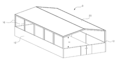
이와 같이, 대기 중의 오염 물질이 축사 내부로 유입되는 것을 억제하기 위해서는, 도1에 도시된 바와 같이, 외기와 밀폐된 형태의 축사(9)로 형성된 경우에만 가능하다. 즉, 창문(12)이 개방될 수 있더라도, 벽면(10)에 의해 측면이 밀폐되고, 지붕(20)에 의해 천장이 밀폐되어 있어야 하며, 주로 환풍기(14)에 의해서만 외기의 공기를 강제로 유입하거나 유출시키는 구조의 축사(9)이어야 한다. As such, in order to suppress the inflow of contaminants in the atmosphere into the house, as shown in Figure 1, it is possible only when formed with the
그러나, 일반적으로, 도2에 도시된 바와 같이, 지붕(20)과 측벽(10')의 사이에는 소정의 높이(H)만큼 기둥(16)만으로 연결되어 외기가 유입되기 용이한 공간이 마련된 개방형 축사도 널리 사용되고 있으므로, 개방형 축사(9')는 상기 기술이 적용될 수 없는 한계가 있다. However, in general, as shown in FIG. 2, the
또한, 개방형 축사(9')는, 비가 오거나 추운 날씨에, 지붕(20)으로부터 말려있는 비닐 막을 하방으로 펼쳐 기둥(16) 사이의 빈 공간을 막아, 개방형 축사(9')의 내부와 외부를 차단하기도 하지만, 비닐 막을 펼치는 것에 의해 내부와 외부를 완전히 차단하는 것은 어려운 한계가 있다.In addition, the open barn 9 ', in rainy or cold weather, spreads the plastic film rolled from the
더욱이, 밀폐형 축사(9)는 외기의 유입이 제한적이어서, 내부의 가축이나 가금류의 배설물에 의한 오염이 오히려 더 큰 문제가 야기될 수 있다. Moreover, the closed
따라서, 밀폐형 축사(9)와 개방형 축사(9')에 무관하게, 축사 내부를 충분히 살균하여 서식하는 가축과 가금류에 구제역이나 조류독감 바이러스 등의 병원균이 감염되는 것을 억제하는 방안의 필요성이 절실히 모색되고 있다. Therefore, regardless of the closed barn (9) and the open barn (9 '), there is an urgent need to find a way to prevent infection of pathogens such as foot-and-mouth disease or bird flu virus from livestock and poultry that live by sterilizing the inside of the barn. Is becoming.
한편, 일상 생활에서 널리 사용하는 주방 식기나, 비데, 샤워 등의 시설이나 높은 압력으로 물을 분사하여 치아를 세정하는 치아 세정기 등에서도 미생물, 박테리아 등에 의한 오염 문제가 대두되고 있다. On the other hand, contamination problems caused by microorganisms, bacteria, etc. are emerging in kitchen utensils widely used in daily life, facilities such as bidets, showers, and tooth cleaners that spray water with high pressure to clean teeth.
냄비, 칼, 수저, 도마 등의 주방 식기는 음식물과 접촉하고, 충분히 씻어 제거되지 않으면 균이 주방 식기에 오염되어, 오염된 주방 식기로 요리하거나 오염된 주방 식기에 담긴 음식을 섭취하면서 감염의 우려가 있다. 또한, 화장실에 사용되는 비데는 물을 분사하는 튜브의 오염이 널리 알려져 있으며, 샤워 시설도 마찬가지로 샤워기 내부의 오염이 심각한 문제로 되어 왔다.Kitchen utensils such as pots, knives, cutlery, cutting boards, etc., come into contact with food and, if not washed and removed sufficiently, germs become contaminated with kitchen utensils. There is. In addition, in the bidet used for the toilet, the pollution of the tube for spraying water is widely known, and in the shower facility, the pollution inside the shower has also become a serious problem.
이와 유사하게, 치아 사이에 끼어 잔류하는 이물질을 제거하기 위하여 고압으로 물을 분사하는 치아 세정기(예를 들어, 워터픽)에서도, 고압의 물이 통과하는 경로의 튜브 오염이 위생 문제로 거론되어 왔다. Similarly, in tooth cleaners (for example, watermarks) in which water is injected at high pressure to remove foreign substances interposed between teeth, tube contamination in a path through which high pressure water passes has been discussed as a hygiene problem. .
이와 같은 오염 문제를 해소하기 위하여, 짧은 시간에 충분한 양의 살균수를 제조하여 균을 제거하는 형태로 사용할 수 있게 하는 방안의 필요성이 절실히 요구되고 있다. In order to solve the contamination problem, there is an urgent need for a method of preparing a sufficient amount of sterilized water in a short time and using it in a form of removing bacteria.
상기와 같은 문제점을 해소하기 위하여, 본 발명은, 짧은 시간에 다량의 살균수를 제조하는 살균 전극의 제작 방법을 제공하는 것을 목적으로 한다.In order to solve the above problems, an object of the present invention is to provide a method of manufacturing a sterilizing electrode for producing a large amount of sterilizing water in a short time.
무엇보다도, 본 발명은 서로 대향하는 음전극과 양전극이 다수의 통전경로를 형성하여 보다 효율적인 액체의 전기 분해를 통해 사용 전력과 백금 소모량을 최소화하면서 높은 살균 능력을 갖는 살균 성분을 생성하는 것을 목적으로 한다. Above all, the present invention aims to produce a sterilizing component having a high sterilizing ability while minimizing power consumption and platinum consumption through more efficient electrolysis of liquid by forming a plurality of current paths in which negative and positive electrodes facing each other form a more efficient electric path. .
특히, 본 발명은, 살균 전극에 도금층에 비하여 두꺼운 백금층을 간단한 제조 방법으로 형성하는 구조를 가짐에 따라, 축사와 같이 장시간 동안 전극의 교체 없이 전기 분해에 의해 다량의 살균수를 지속적으로 생성할 수 있도록 하고, 경제성을 확보하는 것을 목적으로 한다.Particularly, according to the present invention, as the sterilizing electrode has a structure in which a thick platinum layer is formed by a simple manufacturing method compared to a plating layer, a large amount of sterilizing water can be continuously generated by electrolysis without replacement of the electrode for a long time, such as a barn. It aims at making it possible and securing economic feasibility.
즉, 본 발명은 두꺼운 백금층을 갖는 살균 전극을 쉽고 간단하게 제조하는 것을 목적으로 한다. That is, the present invention aims to easily and simply manufacture a sterilizing electrode having a thick platinum layer.
그리고, 본 발명은, 장시간 동안 다량의 살균수를 지속적으로 제조하는 것을 목적으로 한다.And, an object of the present invention is to continuously produce a large amount of sterilized water for a long time.
또한, 본 발명은, 미사용된 고가의 백금을 재사용할 수 있도록 하여 경제성을 향상시키는 것을 목적으로 한다.In addition, an object of the present invention is to improve economic efficiency by allowing unused expensive platinum to be reused.
본 발명은, 상기와 같이 제작된 살균 전극을 이용하여, 폐쇄형 축사와 개방형 축사에 모두 적용할 수 있는 살균 장치를 제공하는 것을 목적으로 한다.An object of the present invention is to provide a sterilizing device that can be applied to both a closed house and an open house using a sterilizing electrode manufactured as described above.
본 발명은, 환기가 잘 이루어지면서도 축사 내부를 효과적으로 살균하는 것을 목적으로 한다. An object of the present invention is to effectively sterilize the inside of a house while ventilation is well performed.
본 발명은, 상기와 같이 제작된 살균 전극을 이용하여, 짧은 시간 동안에 다량으로 생성된 살균수를 이용하여 치아 세정기, 비데, 샤워 시설의 물공급 관, 주방 식기 등 다양한 대상물을 살균하는 것을 목적으로 한다. The present invention is for the purpose of sterilizing various objects such as tooth cleaners, bidets, water supply pipes of shower facilities, kitchen utensils, etc., using sterilized water produced in a large amount in a short time by using the sterilizing electrodes manufactured as described above. do.
상술한 본 발명의 목적들을 달성하기 위하여, 본 발명은, 염소가 함유된 액체 내에서 서로 대향하게 배치된 제1전극 및 제2전극을 포함하고, 상기 제1전극과 상기 제2전극에 전원이 공급되어 상기 액체 내에 살균 성분을 생성하는 살균 전극으로서, 전기 전도성 재료로 형성되고 대향면이 구비되며 상기 전원과 연결되는 전도체와; 상기 전도체의 상기 대향면에 적층되는 백금 재질의 백금층과; 상기 전도체와의 사이에 상기 백금층을 개재시킨 상태로 상기 전도체에 고정되되, 관통부가 구비되어, 상기 관통부를 통해 상기 백금층의 일부인 제1영역을 다수의 위치에 드러나게 하고, 상기 제1영역 이외의 나머지 영역은 가려진 상태로 상기 백금층의 외표면을 덮어 형성하는 절연 재질의 절연체를; 포함하여 구성된 것을 특징으로 하는 살균 전극을 제공한다. In order to achieve the above-mentioned objects of the present invention, the present invention includes a first electrode and a second electrode disposed opposite to each other in a liquid containing chlorine, and the first electrode and the second electrode are powered. A sterilizing electrode that is supplied and generates a sterilizing component in the liquid, the conductor being formed of an electrically conductive material and having an opposite surface and connected to the power source; A platinum layer made of a platinum material laminated on the opposite surface of the conductor; It is fixed to the conductor with the platinum layer interposed between the conductors, but is provided with a through portion, through which the first region, which is part of the platinum layer, is exposed to a plurality of locations, and other than the first region. The rest of the region is covered with an insulator made of an insulating material covering and forming the outer surface of the platinum layer; It provides a sterilizing electrode characterized in that it comprises a.
이는, 대향하는 전극 사이에서의 통전 경로를 서로 이격된 다수의 제1영역으로 형성하는 것을 백금층을 덮는 절연체의 관통부에 의해 형성함으로써, 다수의 통전 경로를 형성하는 것을 간단히 제조할 수 있도록 하기 위함이다.This makes it easy to manufacture forming a plurality of conduction paths by forming the conduction paths between opposing electrodes as a plurality of first regions spaced apart from each other by a through portion of an insulator covering the platinum layer. It is for sake.
무엇보다도, 상기 백금층은 백금 박판을 상기 대향면에 적층하는 것에 의해 형성될 수 있다. 예를 들어, 상기 백금 박판은 20㎛ 내지 3mm의 두께로 형성되어, 일반적인 백금 도금층의 두께인 3㎛에 비해 훨씬 두꺼운 두께로 성형하는 것이 가능해진다. Above all, the platinum layer can be formed by laminating a platinum thin plate on the opposite surface. For example, the platinum thin plate is formed to a thickness of 20 µm to 3 mm, so that it can be molded to a much thicker thickness than 3 µm, which is a typical platinum plating layer.
다시 말하면, 종래의 전극은 백금(Pt)이 약 3㎛의 얇은 도금층으로 전극에 형성됨에 따라, 대략 300 ~ 500mA의 낮은 전류가 인가되는 경우에 하루 15분간 30일 작동하면 더이상 전기 분해를 할 수 없는 문제가 있을 뿐만 아니라, 10A 이상의 높은 전류를 인가하는 경우에는 1시간도 전기 분해를 지속하지 못하는 심각한 문제가 있었다. 그러나, 본 발명은, 충분히 두꺼운 두께의 백금체를 덩어리 형태로 제1영역(120A)에 결합함에 따라 10A 이상의 고전류(예를 들어, 30A~40A)가 인가되더라도 열흘 이상 전기 분해를 신뢰성있게 행할 수 있는 효과를 얻을 수 있다. In other words, as the conventional electrode is formed on the electrode with a thin plating layer of about 3 µm of platinum (Pt), it can no longer be electrolyzed if it is operated for 30 minutes for 15 minutes a day when a low current of approximately 300 to 500 mA is applied. Not only was there a problem, but when applying a high current of 10 A or more, there was a serious problem that electrolysis could not be continued for 1 hour. However, the present invention can reliably perform electrolysis for 10 days or more even when a high current of 10A or more (for example, 30A to 40A) is applied as the platinum body of sufficiently thick thickness is coupled to the
즉, 백금층의 두께를 도금에 의해 형성하는 것에 비하여 훨씬 더 두껍게 형성할 수 있게 되어, 훨씬 더 높은 전류를 장시간 동안 인가하더라도, 오랜 시간 동안 신뢰성있게 전기 분해를 지속하면서 살균수를 제조할 수 있는 유리한 효과를 얻을 수 있다.That is, the thickness of the platinum layer can be formed to be much thicker than that formed by plating, so that even if a much higher current is applied for a long time, sterilized water can be produced while reliably maintaining electrolysis for a long time. Advantageous effects can be obtained.
또한, 백금 박판이 전도체의 대향면에 부착되지 아니하고 적층된 형태로 얹혀짐에 따라, 외부에 드러나 통전 경로를 형성하는 제1영역의 백금이 모두 소모된 상태가 되면, 절연체를 전도체로부터 분리하여 제1영역을 제외한 영역의 백금을 쉽게 수거하여 백금을 다시 활용할 수 있다. 백금은 연성이 매우 우수하므로, 백금을 추가하여 원래 두께의 백금 박판으로 성형하거나 보다 얇은 두께의 백금 박판으로 성형하여 살균 전극에 다시 활용할 수도 있다.In addition, when the platinum thin plate is not attached to the opposite surface of the conductor and is placed in a stacked form, when the platinum in the first region that is exposed to the outside and forms a conduction path is exhausted, the insulator is separated from the conductor to remove the Platinum in areas other than
이를 위하여, 절연체는 전도체에 결합될 때에 분리 가능하게 결합되고, 백금 박판은 전도체로부터 분리 가능하게 얹혀지는 것이 바람직하다. 예를 들어, 절연체는 백금 박판을 사이에 두고 전도체에 끼워 조립될 수도 있고, 전도체에 볼트 체결 등에 의해 조립되는 형태로 결합될 수 있다. 즉, 절연체는 백금 박판을 위치 고정하는 역할과 관통부에 의해 통전 경로를 형성하는 제1영역만을 외부에 드러나게 하는 역할을 한다. To this end, the insulator is detachably coupled when coupled to the conductor, and it is preferable that the platinum thin plate is detachably mounted from the conductor. For example, the insulator may be assembled by sandwiching a thin platinum plate between the conductors and assembled to the conductor by bolting or the like. That is, the insulator serves to position the platinum thin plate and to expose only the first region forming the conduction path by the through portion to the outside.
예를 들어, 상기 절연체는 플라스틱, 수지, 폴리우레탄, 고무 중 어느 하나의 재질로 형성될 수 있다. For example, the insulator may be formed of any one of plastic, resin, polyurethane, and rubber.
한편, 상기 백금층은 상기 대향면에 백금 도금된 층으로 이루어지고, 상기 절연체는 격자 형상으로 형성되어, 격자의 사이에 형성된 상기 관통부가 통전 경로를 형성하는 상기 제1영역을 형성할 수도 있다. 이는, 백금층을 전도체로부터 분리하여 재사용 측면과 충분히 두꺼운 두께로 형성하는 측면에서 불리하지만, 다수의 통전 경로를 형성하기 위하여 복잡한 형상으로 전도체를 성형하지 아니하여도 되므로, 다수의 통전 경로를 형성하는 제1영역을 격자 모양의 절연체에 의해 쉽게 형성할 수 있는 이점을 얻을 수 있다.On the other hand, the platinum layer is made of a layer plated with platinum on the opposing surface, and the insulator is formed in a lattice shape to form the first region in which the through portion formed between the lattices forms a conduction path. This is disadvantageous in that the platinum layer is separated from the conductor to form a reusable side and a sufficiently thick thickness, but it is not necessary to form the conductor in a complicated shape in order to form a plurality of conduction paths, thereby forming a plurality of conduction paths. It is possible to obtain an advantage that the first region can be easily formed by a lattice-shaped insulator.
한편, 상기 전도체는 전기 전도도가 우수한 티타늄, 구리으로 형성될 수 있다.Meanwhile, the conductor may be formed of titanium or copper having excellent electrical conductivity.
그리고, 상기 절연체는 서로 다른 위치에 관통부가 형성된 형태로 교체 가능하게 형성되어, 백금 박판의 제1영역이 전기 분해에 의해 기준치 이상 소모되면, 새로운 백금 박판으로 교체할 수 있다. In addition, the insulator is formed to be replaceable in a form in which through portions are formed at different positions, and when the first region of the platinum thin plate is consumed above a reference value by electrolysis, it can be replaced with a new platinum thin plate.
여기서, 상기 제1전극과 상기 제2전극은 상기 전도체, 상기 절연체, 상기 백금 박판을 포함하여 형성되고, 상기 제1전극의 상기 제1영역과 상기 제2전극의 상기 제2영역은 서로 대향하는 위치에 정렬되어, 제1전극의 제1영역과 제2전극의 제1영역을 잇는 다수의 통전 경로가 서로 이격되게 형성하는 신뢰성을 높일 수 있다.Here, the first electrode and the second electrode are formed including the conductor, the insulator, and the platinum thin plate, and the first region of the first electrode and the second region of the second electrode face each other. Aligned to the position, it is possible to increase the reliability of forming a plurality of energizing paths spaced apart from each other, connecting the first region of the first electrode and the first region of the second electrode.
즉, 제1전극의 제1영역과 제2전극의 제1영역이 서로 마주보게 형성되어, 각 전극의 백금 박판에 전류가 공급되면, 전류의 전하가 살균 전극의 백금 박판의 제1영역으로 집중되면서, 서로 마주보는 제1영역 사이에서 전하가 이동하면서 통전 경로를 형성하고 전기 분해를 발생시킨다. 이와 같이, 서로 마주보는 제1영역 사이에서 전하가 통전되면서 살균수가 생성됨에 따라, 산화체, 차아염소산 등의 살균 성분의 생성량을 보다 높이면서 살균 성분의 생성량을 보다 정교하게 조절할 수 있다.That is, when the first region of the first electrode and the first region of the second electrode are formed to face each other, when current is supplied to the platinum thin plate of each electrode, the charge of the current is concentrated to the first region of the platinum thin plate of the sterilizing electrode. As it is, charges move between the first regions facing each other to form a conduction path and generate electrolysis. As such, as the sterilizing water is generated while electric charges are applied between the first regions facing each other, the amount of sterilizing components, such as oxidizer and hypochlorous acid, can be increased and the amount of sterilizing components can be more precisely controlled.
예를 들어, 상기 살균 전극은 축사에 공급하는 살균수의 제조에 사용될 수 있다.For example, the sterilizing electrode can be used for the production of sterilizing water supplied to the house.
한편, 발명의 다른 분야에 따르면, 살균 전극의 제조 방법으로서, 전기 전도성 재료로 형성되고 대향면이 형성된 전도체를 준비하는 전도체 준비단계와; 미리 정해진 두께의 백금 박판을 준비하여 상기 대향면에 얹혀 적층시키는 백금박판 거치단계와; 다수의 관통부가 형성된 절연 재질의 절연체를 준비하여, 상기 전도체와의 사이에 상기 백금 박판을 개재시킨 상태로 상기 전도체에 고정시키는 절연체 고정단계를; 포함하여 구성되어, 상기 관통부를 통해 상기 백금 박판의 일부인 제1영역을 드러나게 하고 제조하는 것을 특징으로 하는 살균 전극의 제조 방법을 제공한다.On the other hand, according to another field of the invention, a method of manufacturing a sterile electrode, comprising: a conductor preparation step of preparing a conductor formed of an electrically conductive material and having an opposite surface; A platinum thin plate mounting step of preparing a platinum thin plate of a predetermined thickness and stacking it on the opposite surface; Preparing an insulator made of an insulating material having a plurality of through portions and fixing the insulator to the conductor in a state in which the platinum thin plate is interposed between the conductors; It is configured to include, it provides a method for manufacturing a sterilizing electrode, characterized in that to expose and manufacture a first region that is part of the platinum thin plate through the through portion.
여기서, 상기 절연체 고정단계는 상기 절연체를 상기 전도체로부터 분리 가능하게 상기 전도체에 고정시키는 것이 바람직하다. 이를 통해, 제1영역에서의 백금 소모량이 기준치 이상이 되면 백금 박판을 교체할 수 있으며, 관통부의 위치가 다르게 형성된 절연체로 교체하여 사용한 백금 박판의 미사용 영역으로 전기 분해를 지속하게 할 수 있다.Here, in the fixing of the insulator, it is preferable to fix the insulator to the conductor so as to be detachable from the conductor. Through this, when the platinum consumption in the first region exceeds the reference value, the platinum thin plate can be replaced, and the electrolysis can be continued to the unused region of the used platinum thin plate by replacing it with an insulator having a different through position.
여기서, 상기 절연체는 격자 형상으로 형성되어, 격자의 사이에 형성된 상기 관통부가 상기 제1영역을 형성함으로써, 제1전극과 제2전극 사이의 다수의 통전 경로를 서로 균일하게 이격되게 형성하여 차아염소산 등의 살균 성분의 생성량을 보다 높일 수 있다.Here, the insulator is formed in a lattice shape, and the through portion formed between the lattices forms the first region, thereby forming a plurality of conduction paths between the first electrode and the second electrode to be uniformly spaced from each other, and hypochlorous acid. It is possible to further increase the production amount of sterilizing components such as.
한편, 본 발명은, 염소를 포함하는 액체를 수용하는 수용부와; 상기 수용부의 액체에 일부 이상 잠기게 배치되는 전술한 구성의 살균 전극과; 상기 살균 전극에 전원을 인가하는 전원 공급부를; 포함하는 살균 장치를 제공한다.On the other hand, the present invention, a receiving portion for receiving a liquid containing chlorine; A sterilizing electrode having the above-described configuration, which is arranged to be immersed in at least a part of the liquid of the receiving part; A power supply for applying power to the sterilizing electrode; It provides a sterilizing device comprising.
이와 같이, 충분히 두껍고 분리 가능한 백금 박판의 제1영역에 생성되는 통전 경로에서 전기 분해가 이루어짐에 따라, 제1전극과 제2전극의 사이에서 액체의 전기 분해에 의해 차아염소산(HOCl), OH라디칼, 과산화수소 등의 산화체(oxidants)가 살균 성분으로 생성되면서, 액체를 살균수로 제조하게 된다. 이를 위하여, 액체에는 염소(Cl) 성분을 함유하고 있는 것이 바람직하다. 그리고, 차아염소산은 인체에 무해하면서도 높은 살균력을 갖고 있으므로, 차아염소산의 생성량을 높이기 위하여, 액체의 pH값은 3.0 내지 8.0의 범위인 것이 바람직하다. As described above, as electrolysis is performed in the energization path generated in the first region of the sufficiently thin and separable platinum thin plate, hypochlorous acid (HOCl) and OH radicals are obtained by electrolysis of the liquid between the first electrode and the second electrode. , As oxidants such as hydrogen peroxide are produced as sterilizing components, the liquid is prepared as sterilizing water. To this end, it is preferable that the liquid contains a chlorine (Cl) component. In addition, hypochlorous acid is harmless to the human body and has a high sterilizing power. Therefore, in order to increase the amount of hypochlorous acid, the pH value of the liquid is preferably in the range of 3.0 to 8.0.
여기서, 상기 제1전극과 상기 제2전극은 상기 전도체, 상기 절연체, 상기 백금 박판을 포함하여 형성되고, 상기 제1전극과 상기 제2전극은 상기 절연체의 관통부에 의해 형성된 제1영역이 서로 마주보게 정렬되게 구성할 수 있다. Here, the first electrode and the second electrode are formed including the conductor, the insulator, and the platinum thin plate, and the first electrode and the second electrode have a first region formed by a through portion of the insulator to each other. It can be configured to face to face.
그리고, 상기 살균 전극에 전원을 공급하여 생성된 살균 성분을 함유한 살균수를 공급하는 살균수 공급부를; 더 포함하여, 살균하고자 하는 다양한 대상물에 살균수를 공급할 수 있다.In addition, a sterilizing water supply unit for supplying sterilizing water containing sterilizing components generated by supplying power to the sterilizing electrode; In addition, sterilized water can be supplied to various objects to be sterilized.
예를 들어, 상기 살균수 공급부는 다수의 분무구가 구비된 공급 바가 상기 축사의 천장부에 다수 열로 배치되어, 축사 내부의 살균에 활용할 수 있다.For example, the sterilizing water supply unit is provided with a plurality of spray holes is provided in a number of rows in the ceiling of the house, it can be utilized for sterilization inside the house.
그리고, 산화체 생성을 위한 살균 전극은 고인 액체 내에 설치되어, 고인 액체 내에서 살균 성분을 생성할 수도 있지만, 본 발명은 이에 한정되지 아니한다. 즉, 본 발명은, 제1전극과 제2전극을 한 쌍으로 하는 살균 전극은 액체가 유동하고 있는 액체 유동장 내에 설치될 수 있다. In addition, although the sterilizing electrode for generating an oxidizing body is installed in the deceased liquid, a sterilizing component may be generated in the deceased liquid, but the present invention is not limited thereto. That is, in the present invention, a sterilizing electrode having a pair of first and second electrodes can be installed in a liquid flow field in which liquid is flowing.
즉, 상기 액체를 공급하는 공급 파이프의 중간에 상기 수용부가 배치되어, 상기 수용부에 수용된 상기 살균 전극에 의해 상기 공급 파이프를 통해 공급되는 액체에 살균 성분을 실시간으로 생성하여, 살균 성분이 함유된 살균수를 살균하고자 하는 대상물, 예를 들어, 치아 세정기, 수도관, 비데, 정수기 등에 상기 살균수를 공급할 수도 있다.That is, the receiving portion is disposed in the middle of the supply pipe for supplying the liquid, and the sterilizing component is generated in real time in the liquid supplied through the supply pipe by the sterilizing electrode accommodated in the receiving portion, and the sterilizing component is contained. The sterilizing water may be supplied to an object to be sterilized, for example, a tooth cleaner, a water pipe, a bidet, and a water purifier.
여기서, 살균 전극이 배치된 상기 수용부는 액체 유동장의 유동 단면이 다른 영역에 비하여 보다 더 큰 ST영역에 배치되어, 살균 전극을 통과하는 액체의 유속이 보다 낮은 상태로 유도함에 따라, 살균 전극에서 생성된 살균 성분이 액체 내에 보다 다량으로 포함되게 유도할 수 있다. Here, the receiving portion in which the sterilizing electrode is disposed is disposed in a larger ST region in which the flow cross-section of the liquid flow field is larger than in other regions, and thus the flow rate of the liquid passing through the sterilizing electrode is induced in a lower state, and thus is generated in the sterilizing electrode. The sterilized ingredients can be induced to be contained in a larger amount in the liquid.
이와 함께, 상기 ST영역은 상기 액체가 유동하는 관로로부터 절곡된 부분의 사이에 배치되어, 액체의 유동 경로가 굽어져 유동 방향의 변경에 의한 마찰로 인해 유속을 감소시킨 상태에서 살균 전극을 액체가 통과하게 함으로써, 유동 중인 액체 내에 보다 많은 살균 성분이 함유되어 보다 높은 살균수를 실시간으로 제조할 수 있게 된다.At the same time, the ST region is disposed between the bent portion from the pipe through which the liquid flows, and the liquid flow path is bent to reduce the flow rate due to friction due to the change in the flow direction, thereby disinfecting the sterilizing electrode. By allowing it to pass through, more sterilizing components are contained in the flowing liquid, so that higher sterilizing water can be produced in real time.
여기서, 제1전극과 제2전극에는 종래에 비하여 매우 두꺼운 백금 박판의 제1영역이 서로 대향하여 전기 분해에 관여하므로, 높은 전류를 인가하더라도 장시간 동안 백금체가 유지될 수 있다. 따라서, 살균 전극에 인가되는 전류는 10A 이상의 높은 전류가 인가될 수 있으며, 10A(암페어) 내지 50A의 높은 전류를 공급할 수 있다.Here, since the first regions of the first and second electrodes are very thick in comparison to the prior art, the first regions of the thin platinum plates face each other and are involved in electrolysis, so that even when a high current is applied, the platinum body can be maintained for a long time. Therefore, a high current of 10 A or more can be applied to the current applied to the sterilizing electrode, and a high current of 10 A (ampere) to 50 A can be supplied.
상기와 같이 구성된 살균 장치는 다양하게 적용될 수 있다. 즉, 상기와 같이 구성된 살균 장치는 살균 전극의 다수의 제1영역이 서로 마주보게 배치되어, 제1영역 사이에서 통전되는 전류(전하)에 의해 생성되는 살균수의 단위 시간당 생성량이 일정하게 조절되는 이점이 있으므로, 전체적으로 균일한 살균 성분을 함유한 살균수를 짧은 시간에 다량으로 생산하여 다양한 용도에 활용될 수 있다.The sterilizing device configured as described above can be applied in various ways. That is, in the sterilizing apparatus configured as described above, a plurality of first regions of the sterilizing electrode are disposed to face each other, and the amount of production per unit time of sterilizing water generated by the current (charge) that is energized between the first regions is constantly adjusted. Since there is an advantage, it can be utilized for various purposes by producing a large amount of sterilized water containing a uniform sterilizing component in a short time.
먼저, 전술한 구성의 살균 장치에 의해 제조된 살균수를 살균수 공급부에 의해 축사에 공급할 수 있다. 상기 살균 장치는 다량의 살균수를 장기간 동안에 신뢰성있는 범위의 농도를 유지하면서 제조할 수 있으므로, 넓은 축사에도 지속적으로 살균수를 공급하여, 축사 내의 병원균을 사멸시켜 위생적인 축사로 유지할 수 있다. First, the sterilized water produced by the sterilizing device of the above-described configuration can be supplied to the house by the sterilizing water supply unit. Since the sterilizing device can manufacture a large amount of sterilizing water while maintaining a reliable range of concentration for a long period of time, the sterilizing water can be continuously supplied to a wide barn to kill pathogens in the barn to maintain a hygienic barn.
특히, 축사 내부로 유입되는 공기를 멸균시키는 것이 아니므로, 축사 내부에 병원균이 유입되더라도, 충분한 양의 살균수를 공기중에 분무하는 것에 의하여, 축사 내부의 넓은 공간을 살균시키는 유리한 효과를 얻을 수 있다.In particular, since the air flowing into the house is not sterilized, even if a pathogen enters the house, by spraying a sufficient amount of sterilizing water in the air, an advantageous effect of sterilizing a large space inside the house can be obtained. .
예를 들어, 축사 내부에 살균수를 공급하는 살균수 공급부는 다수의 분무구가 구비된 공급 바가 상기 축사의 천장부에 다수 열로 간격을 두고 배치되어, 축사의 내부 공간에 골고루 살균수를 분무 형태로 스프레이(spray)하여 청결하고 위생적인 환경을 유지할 수 있다.For example, the sterilizing water supply unit for supplying sterilizing water to the inside of the barn is provided with a plurality of spray holes, and a supply bar is disposed at a plurality of rows at the ceiling of the barn to distribute the sterilizing water evenly in the interior space of the barn. Spraying can maintain a clean and hygienic environment.
그리고, 상기와 같이 구성된 살균 장치는 액체를 공급하는 액체 이송관을 살균 세정하는 용도로 활용될 수도 있다. 즉, 상기와 같이 구성된 살균 장치에서 제조된 살균수를 제조하면서 살균하고자 하는 대상물의 액체 이송관에 통과시키는 것에 의해, 상기 액체 이송관의 내부를 살균시킬 수 있다.In addition, the sterilizing device configured as described above may be utilized for the purpose of sterilizing and cleaning the liquid transport pipe supplying the liquid. That is, the inside of the liquid transfer pipe can be sterilized by passing through the liquid transfer pipe of the object to be sterilized while manufacturing the sterilized water produced by the sterilizing apparatus configured as described above.
예를 들어, 워터 픽과 같은 치아 세정기나, 수도관, 비데, 정수기에 물 등을 공급하는 액체 이송관의 내부 벽면을 살균 세정하는 용도로 활용될 수 있다.For example, it can be used for the purpose of sterilizing and cleaning the inner wall surface of a liquid cleaning pipe that supplies water, etc. to a tooth cleaner such as a water pick or a water pipe, bidet, or water purifier.
그 밖에, 주방에서 사용하는 주방 식기나 칼, 도마 등을 세정하는 데에도 활용할 수 있다. 즉, 본 발명에 따른 살균 장치는 짧은 시간에 다량의 살균수를 신뢰성있는 범위의 농도로 살균 성분의 비율을 유지하면서 지속적으로 장시간동안 제조하는 것이 가능하므로, 인체의 눈, 코, 점막 등과 같이 민감한 부분을 제외하고는 넓은 범위에 활용될 수 있다.In addition, it can be used to clean kitchen utensils, knives and cutting boards used in the kitchen. That is, the sterilizing device according to the present invention can be manufactured for a long period of time while maintaining the proportion of sterilizing components in a reliable range of concentration of a large amount of sterilizing water in a short time, so sensitive to the human eye, nose, mucous membrane, etc. It can be used in a wide range except for parts.
상술한 바와 같이 본 발명에 따르면, 백금층의 일부만 드러나게 하는 절연체를 이용하여 다수의 통전 경로를 위한 다수의 제1영역을 서로 이격되게 형성한 살균 전극을 제공한다. As described above, according to the present invention, a sterilizing electrode in which a plurality of first regions for a plurality of energizing paths are spaced apart from each other by using an insulator that exposes only a portion of the platinum layer is provided.
이를 통해, 액체의 전기 분해를 위해 다수의 통전 경로를 형성하는 살균 전극의 제조를 보다 용이하게 할 수 있는 효과를 얻을 수 있다.Through this, it is possible to obtain an effect of facilitating the manufacture of a sterilizing electrode that forms a plurality of energizing paths for electrolysis of liquid.
또한, 본 발명은 절연체의 관통부에 의해 드러난 백금층의 제1영역에 의해 다수의 통전 경로가 정해진 간격으로 이격되게 형성하여, 통전 경로 상에서의 전기 분해에 의해 살균 성분을 균일하게 생성하는 효과를 얻을 수 있다.In addition, the present invention has the effect of uniformly generating sterilizing components by electrolysis on the energizing path by forming a plurality of energizing paths spaced apart at predetermined intervals by the first region of the platinum layer exposed by the penetration of the insulator. Can be obtained.
즉, 본 발명은 서로 대향하는 음전극과 양전극이 다수의 통전경로를 형성하여 보다 효율적인 액체의 전기 분해를 통해 사용 전력과 백금 소모량을 최소화하면서 높은 살균 능력을 갖는 살균 성분을 생성하는 효과를 얻을 수 있다.That is, the present invention can obtain the effect of generating a sterilizing component having a high sterilizing ability while minimizing power consumption and platinum consumption through more efficient electrolysis of liquid by forming a plurality of current paths in which the negative and positive electrodes facing each other form a more efficient electrolysis. .
특히, 본 발명은, 전도체의 대향면에 백금층을 백금 박판을 얹혀 적층하여 형성함에 따라, 도금에 의해 형성할 수 없는 큰 두께가 되도록 백금층을 자유자재로 형성하여, 높은 전류와 전압이 인가되더라도 장시간 동안 지속적으로 신뢰성있게 단위 시간당 살균 성분을 다량으로 생성하는 효과를 얻을 수 있다. In particular, according to the present invention, as a platinum layer is formed by laminating a platinum thin plate on an opposite surface of a conductor, a platinum layer is freely formed to have a large thickness that cannot be formed by plating, and high current and voltage are applied. Even if possible, it is possible to obtain an effect of continuously producing a large amount of sterilizing components per unit time for a long time.
더욱이, 본 발명은, 백금 박판이 전도체에 부착되거나 접착되지 아니하고 얹혀 적층 형성됨에 따라, 서로 이격된 통전 경로를 형성하는 백금 박판의 제1영역이 소모되면, 새로운 백금 박판으로 간단히 교체하고 사용한 백금 박판은 재처리 하여 다시 사용할 수 있게 됨에 따라, 고가인 백금을 모두 사용하여 손실되는 것을 원천적으로 제거하여 경제성을 높일 수 있다.Moreover, according to the present invention, when the first area of the platinum thin plate forming a conduction path spaced apart from each other is consumed, as the platinum thin plate is stacked without being attached to or attached to the conductor, the platinum thin plate is simply replaced with a new platinum thin plate. As silver can be reprocessed and reused, it is possible to increase the economic efficiency by basically removing the loss by using all of the expensive platinum.
또한, 본 발명은, 통전 경로를 형성하는 제1영역을 형성하는 관통부의 배치가 다른 절연체로 교체 가능하게 형성되어, 전도체에 적층된 백금을 전체적으로 사용할 수 있게 되어 경제성을 높이는 효과를 얻을 수 있다.In addition, according to the present invention, the arrangement of the penetrating portions forming the first region forming the energizing path is replaceable with another insulator, so that the platinum layered on the conductor can be used as a whole, thereby improving the economic efficiency.
그리고, 본 발명은, 살균 전극에 도금층에 비하여 두꺼운 백금층을 접착이나 부착없이 적층하여 제조함에 따라, 백금층의 두께를 자유 자재로 형성하여 축사와 같이 장시간 동안 전극의 교체 없이 전기 분해에 의해 다량의 살균수를 지속적으로 제조하는 효과를 얻을 수 있다. And, according to the present invention, as the platinum layer is manufactured by laminating a thick platinum layer on the sterilizing electrode compared to the plating layer without adhesion or attachment, the thickness of the platinum layer is formed freely, and a large amount is achieved by electrolysis without replacement of the electrode for a long time, such as a house. It is possible to obtain the effect of continuously manufacturing sterilized water.
또한, 본 발명은 두꺼운 백금층을 갖는 살균 전극을 쉽고 간단하게 제조하는 효과를 얻을 수 있다. In addition, the present invention can obtain an effect of easily and simply manufacturing a sterilizing electrode having a thick platinum layer.
또한, 본 발명은, 일정한 농도 범위의 살균 성분을 흐르는 액체 유동장 내에서도 생성하는 유리한 효과를 얻을 수 있다. In addition, the present invention can obtain an advantageous effect generated even in a liquid flow field flowing through a sterilizing component having a constant concentration range.
그리고, 본 발명은, 짧은 시간 내에 다량으로 제조한 살균수를 이용하여 폐쇄형 축사 뿐만 아니라 개방형 축사에 대해서도 위생적이고 청결한 환경을 유지하는 효과를 얻을 수 있다.In addition, the present invention can obtain an effect of maintaining a hygienic and clean environment for not only a closed house but also an open house using sterilized water produced in large quantities within a short time.
또한, 본 발명은, 액체를 공급하는 비데, 치아 세정기, 정수기 등의 다양한 장치의 관로 내부를 깨끗하게 살균 세정할 수 있게 되는 유리한 효과를 얻을 수 있다. In addition, the present invention can obtain an advantageous effect of being able to cleanly sterilize and clean the inside of a pipeline of various devices such as a bidet, a tooth cleaner, a water purifier for supplying a liquid.
도1은 폐쇄형 축사의 외형을 도시한 사시도,
도2는 개방형 축사의 외형을 도시한 사시도,
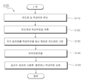
도3은 본 발명의 일 실시예에 따른 살균 전극의 제작 방법을 순차적으로 도시한 순서도,
도4는 살균 전극의 분해 사시도,
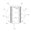
도5는 도4의 살균 전극의 결합 사시도,
도6은 본 발명의 일 실시예에 따른 살균 장치의 구성을 도시한 도면,
도7은 도6의 'A'부분의 확대도,
도8은 본 발명의 다른 실시예에 따른 살균 장치의 구성을 도시한 도면,
도9a는 도5의 평면도,
도9b는 도9a의 살균 전극의 제1영역의 백금이 소모된 상태에서 절연체를 제거한 구성의 평면도,
도9c는 다른 배치의 관통부가 형성된 다른 절연체로 교체한 살균 전극의 평면도,
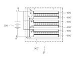
도10은 본 발명에 따라 제작된 살균 전극을 이용한 살균 장치의 구성을 도시한 도면,
도11은 도10의 살균 전극 수용부(ST)의 확대도,
도12는 도10의 살균 장치를 축사의 살균에 활용한 축사용 살균 장치의 개략 사시도이다.1 is a perspective view showing the appearance of a closed house,
Figure 2 is a perspective view showing the appearance of an open house,
Figure 3 is a flow chart sequentially showing a method of manufacturing a sterilizing electrode according to an embodiment of the present invention,
Figure 4 is an exploded perspective view of the sterilizing electrode,
Figure 5 is a perspective view of the combination of the sterilizing electrode of Figure 4,
6 is a view showing the configuration of a sterilization device according to an embodiment of the present invention,
Figure 7 is an enlarged view of part 'A' of Figure 6,
8 is a view showing the configuration of a sterilizing device according to another embodiment of the present invention,
Figure 9a is a plan view of Figure 5,
9B is a plan view of a configuration in which the insulator is removed while platinum in the first region of the sterilizing electrode of FIG. 9A is consumed;
Figure 9c is a plan view of a sterilizing electrode replaced with another insulator having a through portion of a different arrangement,
10 is a view showing the configuration of a sterilizing device using a sterilizing electrode manufactured according to the present invention,
11 is an enlarged view of the sterilizing electrode accommodating part ST of FIG. 10,
12 is a schematic perspective view of a livestock sterilizing device utilizing the sterilizing device of FIG. 10 for sterilizing a livestock house.
이하 첨부된 도면들을 참조하여 본 발명의 바람직한 실시예를 상세하게 설명하지만, 본 발명이 실시예에 의해 제한되거나 한정되는 것은 아니다. 참고로, 본 설명에서 동일한 번호는 실질적으로 동일한 요소를 지칭하며, 이러한 규칙 하에서 다른 도면에 기재된 내용을 인용하여 설명할 수 있고, 당업자에게 자명하다고 판단되거나 반복되는 내용은 생략될 수 있다.Hereinafter, preferred embodiments of the present invention will be described in detail with reference to the accompanying drawings, but the present invention is not limited or limited by the embodiments. For reference, in this description, the same numbers refer to substantially the same elements, and the contents described in other drawings may be cited and explained under these rules, and repeated contents that are determined or apparent to those skilled in the art may be omitted.
도면에 도시된 바와 같이, 본 발명에 따른 살균 장치는, 도6에 도시된 바와 같이, 염소가 함유된 액체(55)를 수용한 수용부(300) 내에서 액체(55)에 일부이상 잠긴 상태로 서로 대향하게 배치된 제1전극(100) 및 제2전극(100')을 포함하는 살균 전극을 포함한다. 여기서, 살균 전극은 제1전극(100)과 제2전극(100')에 전원 공급부(200)로부터 전원이 공급되어 액체(55) 내에서 차아염소산 등의 살균 성분을 생성한다. As shown in the figure, the sterilization device according to the present invention, as shown in Figure 6, the liquid 55 is partially submerged in the liquid 55 within the receiving
여기서, 제1전극(100)은 전원 공급부(200)로부터 양극과 연결되고, 제2전극(200)은 전원 공급부(200)의 음극과 연결되어, 살균 전극에 전원이 인가된다. Here, the
여기서, 살균 전극을 형성하는 제1전극(100)과 제2전극(100') 중 어느 하나 이상은, 전도체(110)와, 전극층(120)과, 절연체(130)로 이루어진다. 도4에는 편의상 제1전극(100)이 도시되어 있지만, 도6에 도시된 제2전극(100')은 제1전극과 동일하게 구성되므로, 제2전극(100')에 관한 설명은 제1전극(100)에 관한 설명으로 대체하기로 한다. Here, at least one of the
상기 전도체(110)는, 티타늄, 구리 등과 같이 전기 전도도가 우수한 전기 전도성 재료로 형성되고, 대향면(110s)이 구비된다. 그리고, 전원 공급부(200)과 연결되는 전원 공급선(112)이 연결된다. The
여기서, 대향면(110s)은 다른 전극의 백금을 향하는 표면을 지칭하며, 도면에 도시된 바와 같이 평탄면으로 형성될 수도 있고, 곡면으로 형성될 수도 있다. Here, the
상기 백금층(120)은 박판 형태의 백금으로 이루어진다. The
본 발명의 일 실시 형태에 따르면, 백금층(120)은 도금에 의해 전도체(110)의 대향면(110s) 상에 형성되는 것을 포함하지만, 도금에 의한 백금층의 두께는 매우 얇아 오랜 시간동안 사용하기가 곤란한 한계가 있다. 다만, 도금에 의해 백금층(120)이 형성되는 경우에도, 후술하는 바와 같이, 절연체(130)의 관통부(132)에 의해 다수의 통전 경로(p)를 형성하는 제1영역(120A)을 쉽게 만들 수 있는 이점이 얻어진다.According to one embodiment of the present invention, the
따라서, 본 발명의 바람직한 실시형태에 따르면, 도4에 도시된 바와 같이, 충분한 두께(t)를 갖는 백금 박판으로 백금층(120)이 형성되는 것이 바람직하다. 예를 들어, 백금 박판은 도금으로 형성하기 어려운 충분히 두꺼운 두께 20㎛ ~ 3mm로 형성될 수 있다. Therefore, according to a preferred embodiment of the present invention, as shown in FIG. 4, it is preferable that the
백금 박판은 전도체(110)의 대향면(110s)에 접착되거나 부착될 수도 있으며, 백금 박판은 전도체(110)의 대향면(110s)에 접착되거나 부착되지 아니하고 얹혀지는 형태로 적층되게 설치될 수 있다. 백금 박판이 전도체(110)에 부착없이 적층되는 것에 의해, 백금 박판을 전도체(110)로부터 쉽게 분리하여 재사용에 활용할 수 있다. The platinum thin plate may be adhered to or attached to the
백금 박판은 전체적으로 균일한 두께로 형성되지만, 본 발명이 이에 국한되는 것은 아니다. 백금은 연성이 우수하므로 롤링에 의해 백금 박판이 제조될 수 있다. The platinum thin plate is formed to a uniform thickness as a whole, but the present invention is not limited thereto. Since platinum is excellent in ductility, a thin platinum plate can be produced by rolling.
상기 절연체(130)는 전기가 통하지 않는 재질로 형성되며, 예를 들어 플라스틱, 수지, 폴리우레탄, 고무 중 어느 하나의 재질로 형성될 수 있다. 절연체(130)에는 다수의 관통부(132)가 형성되며, 백금층(120)을 사이에 두고 전도체(110)에 결합되거나 고정된다. 도5에 도시된 바와 같이, 백금층(120)은 절연체(130)의 관통부(132)를 통해 외부로 드러나며, 관통부(132) 이외의 영역은 절연체(130)에 의해 외부로 드러나지 않게 된다. The
즉, 절연체(130)는 백금 박판을 위치 고정하는 역할과 관통부(132)에 의해 통전 경로를 형성하는 백금층(120)의 제1영역(120A)만을 외부에 드러나게 하는 역할을 한다. That is, the
절연체(130)의 관통부(120A)는 다양한 형상으로 형성될 수 있으며, 예를 들어, 도면에 도시된 바와 같이 격자 형상으로 형성될 수 있다. 특히, 절연체(130)는 격자 형상으로 형성되어, 격자의 사이에 형성된 관통부(132)에 의해 다수의 통전 경로를 형성하는 백금층(120)의 제1영역(120A)이 형성될 수 있다. 절연체(130)가 격자 형태로 형성됨에 따라, 제1영역(120A)은 정해진 간격으로 정확히 배치되므로, 다수의 통전 경로(p) 간의 사이 간격을 일정하게 유지하여, 제1전극(100)과 제2전극(100') 사이에서의 전기 분해에 의해 살균 성분을 균일하게 생성하는 효율을 극대화할 수 있다. The through
도면에는, 절연체(130)의 관통부(132)가 사각 격자 형상인 구성이 예시되어 있지만, 절연체(130)의 관통부(132)는 원형, 타원형, 다각형 형상 중 어느 하나로 형성되거나 이들의 조합으로 형성될 수도 있다.In the drawing, although the configuration in which the through
도4 및 도5에 도시된 바와 같이, 절연체(130)는 외측 연장부(134)가 전도체(110)의 외측면을 감싸면서 끼워지게 구성되어, 절연체(130)는 전도체(110)에 분리 가능하게 끼워 맞춤에 의해 결합된다. 도면에는 절연체(130)와 전도체(110)가 끼워 맞춤에 의해 결합되는 구성이 예시되어 있지만, 본 발명의 다른 실시형태에 따르면, 절연체(130)에 관통공이 형성되어 전도체(110)의 암나사공에 볼트 또는 나사 체결에 의해 결합될 수도 있다(도면에 도시되지 않음). 4 and 5, the
즉, 절연체(130)와 전도체(110)는 다양한 형상으로 형성되어 상호 분리 가능한 다양한 형태로 형성될 수 있으며, 도면에 도시된 형태로 제한되는 것은 아니다.That is, the
따라서, 백금 박판이 전도체(110)의 대향면(110s)에 부착되지 아니하고 적층된 형태로 얹혀짐에 따라, 외부에 드러나 통전 경로(p)를 형성하는 제1영역(120A)의 백금이 모두 소모된 상태가 되면, 절연체(130)를 전도체(110)로부터 분리하여 소모된 제1영역을 제외한 영역의 백금 박판을 간단히 수거하여 백금을 다시 활용할 수 있다. 백금은 연성이 매우 우수하므로, 수거한 백금 박판에 새로운 백금을 추가하여 원래 두께의 백금 박판으로 롤링 성형할 수도 있고, 롤링 성형에 의해 백금을 추가하지 않고 제1영역이 채워진 보다 얇은 두께의 백금 박판으로 성형할 수도 있다. 그리고, 재성형된 백금 박판은 살균 전극에 다시 활용된다. Accordingly, as the platinum thin plate is not attached to the opposing
상기와 같이 구성된 본 발명에 따른 살균 전극(100)은 도3에 도시된 순서도에 따라 제조될 수 있다. The sterilizing
먼저, 도4에 도시된 바와 같이, 티타늄 등의 전기 전도성 재료로 형성되고 대향면(110s)이 형성된 전도체(110)와, 미리 정해진 두께의 백금 박판을 준비한다(S110). First, as shown in FIG. 4, a
그리고 나서, 전도체(110)의 대향면(110s)에 백금 박판을 비접착 형태로 적층하여 거치시키는 백금박판 거치단계를 행한다(S120). Then, a platinum thin plate mounting step of laminating and mounting a platinum thin plate in a non-adhesive form on an
그리고 나서, 다수의 관통부(132)가 형성된 절연 재질의 절연체(130)를 준비하여, 전도체(110)와의 사이에 백금 박판을 백금층(120)으로 개재시킨 상태가 되도록 절연체(130)를 전도체(110)에 고정시키는 절연체 고정단계를 행한다(S130). 이에 따라, 도5에 도시된 바와 같이, 절연체(130)의 관통부(132)를 통해 백금 박판의 일부인 제1영역(120A)을 드러나도록 제조된다. 여기서, 절연체 고정단계는 절연체(130)를 전도체(110)로부터 분리 가능하게 전도체(110)에 고정시키는 것이 바람직하다. Then, an
그리고 나서, 도6에 도시된 바와 같이, 제1전극(100)과 제2전극(100')의 전도체에 외부 전원(200)을 연결하고, 제1전극(100)과 제2전극(100')의 제1영역(120A)이 서로 대향하는 위치에 마주보도록 정렬시킨 후, 제1전극(100)과 제2전극(100')에 전원을 인가한다. 다만, 본 발명은 제1전극(100)과 제2전극(100')이 정렬된 구성에 국한되지 아니하며, 제1전극(100)과 제2전극(100')의 제1영역(120A, 120A')가 어느정도 높이 차이를 두고 서로 완전히 대향되지 않는 형태로 배치될 수도 있다. Then, as illustrated in FIG. 6, the
이에 따라, 제1전극(100)과 제2전극(100')은 절연체(130)의 관통부(132)에 의해 노출된 제1영역(120A)의 사이에서만 전하가 이동하는 통전 경로(p)가 형성된다. 여기서, 통전 경로(p)는 격자 형태의 절연체(130)의 관통부(132) 배치에 따라 서로 정해진 간격이 유지되게 형성된다. 따라서, 통전 경로 상에서의 전기 분해가 균일하게 이루어져, 액체(55) 내에서 차아염소산(HOCl), OH라디칼, 과산화수소 등의 산화체(oxidants)를 살균 성분으로 생성하면서 액체를 살균수로 제조하며, 사용 전력과 백금 소모량을 최소화하면서 높은 살균 능력을 갖는 살균 성분을 생성하는 효과를 얻을 수 있다.Accordingly, the
이를 위하여, 액체에는 염소(Cl) 성분을 함유하고 있는 것이 바람직하다. 그리고, 차아염소산은 인체에 무해하면서도 높은 살균력을 갖고 있으므로, 차아염소산의 생성량을 높이기 위하여, 액체의 pH값은 3.0 내지 8.0의 범위인 것이 바람직하다. To this end, it is preferable that the liquid contains a chlorine (Cl) component. In addition, hypochlorous acid is harmless to the human body and has a high sterilizing power. Therefore, in order to increase the amount of hypochlorous acid, the pH value of the liquid is preferably in the range of 3.0 to 8.0.
도6에 도시된 살균 장치(1)는, 충분히 두꺼운 백금 박판으로 이루어지고 제1영역(120A)에서만 통전 경로(p)를 형성하는 살균 전극(100, 100')을 구비하여, 살균 전극(100, 100')에 높은 전류를 인가하더라도, 다수의 통전 경로 상에서 살균 성분을 효율적으로 생성할 수 있으며 장시간 살균수를 제조하는 공정을 지속할 수 있다. The sterilizing
그러나, 장시간 동안의 살균수를 제조하는 공정 중에 절연체(130)의 관통부(132)에 의해 노출된 제1영역(120A)의 백금층(120)은 소모되며, 기준치 이상 소모되면 절연체(130)나 백금 박판을 교체한다(S150). However, during the process of manufacturing the sterilized water for a long time, the
즉, 도9a에 도시된 바와 같이, 살균 전극을 이루는 제1전극(100)은 절연체(130)의 관통부(132)에 의해 백금이 노출되는 제1영역(120A)이 형성되어 있다. 그러나, 살균 전극의 사용 시간이 경과하여 기준치에 도달하면, 제1영역(120A)의 백금은 소모되는 것이 불가피하다. 따라서, 절연체(130)를 전도체(110)로부터 분리하면, 도9b에 도시된 바와 같이, 제1영역(120A)이었던 백금은 거의 모두 소모된 상태이고, 제1영역(120A) 이외의 영역의 백금은 초기 두께를 그대로 유지하고 있다. That is, as illustrated in FIG. 9A, the
따라서, 도9c에 도시된 바와 같이, 도9a의 절연체(130)의 관통부(132)와 다른 배열로 관통부(132x)가 배열된 다른 절연체(130x)를 전도체(110)에 결합하면, 도9a의 제1영역(120A)과 다른 '120B'로 표시된 위치에 제1영역이 형성되게 된다. 따라서, 제1전극(100)은 절연체(130)를 교체한 도9c의 전극(100x)으로 재사용이 가능해진다. Therefore, as shown in FIG. 9C, when another
한편, 도9b에 도시된 백금층(120)은 제1영역(120A)의 소모량이 많으며, 도9c에 도시된 전극(100x)에서의 새로운 제1영역(120B)도 결국 사용 시간이 경과하면 소모량이 많아져 두께가 얇아진다. 그런데, 백금 박판은 전도체(110)의 대향면(110s)에 접착되어 있지 않고 도금된 것도 아니고 얹혀진 상태로 적층되어 있으므로, 절연체(130)를 전도체(110)로부터 분리한 이후에, 백금 박판을 전도체(110)로부터 분리시키는 것이 매우 용이하다. 따라서, 제1영역이 소모된 백금 박판은 새로운 백금 박판을 제조하는 데 재사용되어, 고가인 백금을 조금이라도 버리지 않고 모두 재사용하는 것이 가능하여 경제성이 높아지는 이점을 얻을 수 있다.On the other hand, the
따라서, 제1영역(120A)에서의 백금 소모량이 기준치 이상이 되면 백금 박판이나 절연체를 교체할 수 있으므로, 살균 전극은 반영구적으로 사용할 수 있게 된다. Therefore, when the platinum consumption in the
한편, 도6 및 도7에 도시된 본 발명의 일 실시 형태는, 살균 장치(1)를 이루는 제1전극(양전극)과 제2전극(음전극)이 모두 전도체(110, 110'), 백금 박판으로 이루어진 백금층(120), 절연체(130)로 이루어져, 절연체(130)의 관통부(132)를 통해 외부에 드러난 제1영역(120A, 120A')의 백금층(120)에 의해 통전 경로(p)가 형성되도록 구성된다. Meanwhile, in the embodiment of the present invention shown in FIGS. 6 and 7, both the first electrode (positive electrode) and the second electrode (negative electrode) constituting the
본 발명의 다른 실시 형태에 따르면, 살균 장치(2)를 이루는 제1전극(100)은 도4 및 도5에 도시된 구성이지만, 도8a에 도시된 바와 같이, 제2전극(101')은 절연체를 구비하지 않게 구성될 수 있다. 이 경우에는 제1전극(100)의 제1영역(120A)으로부터 제2전극(101')으로 분산되는 형태로 전하가 이동하는 통전 경로(p')가 퍼지는 형태로 형성되어, 이 경우에는 도6 및 도7에 도시된 구성에 비해서는 살균 성분의 생성 효율이 저하되지만, 제1전극(100)의 절연체(130)에 의해 서로 구획된 위치로부터 통전 경로(p')가 형성되므로, 전극이 평판으로만 형성된 구성에 비해서는 살균 성분의 생성 효율이 높은 이점을 얻을 수 있다.According to another embodiment of the present invention, the
도8에는 제2전극(101')에 백금층이 형성된 구성이 예시되어 있지만, 본 발명의 다른 실시 형태에 따르면, 제2전극(101')에 백금층이 형성되지 않을 수도 있다. 한편, 도8에는 양전극이 도4 및 도5의 제1전극(100)을 형성하고 음전극이 절연체 없는 전극(101')인 구성이 예시되어 있지만, 본 발명의 다른 실시 형태에 따르면, 음전극이 도4 및 도5의 제1전극(100)을 형성하고 양전극이 절연체 없는 전극(101')인 구성일 수도 있다.Although a configuration in which a platinum layer is formed on the second electrode 101 'is illustrated in FIG. 8, according to another embodiment of the present invention, a platinum layer may not be formed on the second electrode 101'. On the other hand, in FIG. 8, although the positive electrode forms the
한편, 상기와 같이 제작된 살균 전극(100)을 이용한 본 발명의 다른 실시 형태에 따른 살균 장치(3)는, 도10에 도시된 바와 같이, 액체에 일부 이상 잠기는 ST영역(ST)에 설치된 살균 전극(100, 100')과, 살균 전극(100, 100')으로 액체를 공급하는 액체 공급부(1002)와, 액체 공급부(1002)로부터 액체가 이송되는 관로 역할을 하는 액체 공급관(1003)과, ST영역(ST)에서 살균 성분이 함유된 살균수를 사용 용도에 맞게 공급하는 살균수 공급부(500)를 포함하여 구성된다.On the other hand, the sterilization apparatus 3 according to another embodiment of the present invention using the
여기서, 살균 전극(100, 100')은 도5에 도시된 전극이 사용될 수 있다. Here, as the sterilizing
상기 액체 공급부(1002)는 액체 저장 탱크 등으로 형성될 수 있으며, 액체 공급관(1003)에 배치된 펌프(P)를 이용하여 ST영역(ST)을 거쳐 살균수 공급부(500)로 액체를 이송한다. 액체 공급부(1002)로부터 공급되는 액체는 염소 성분을 함유한 것이 바람직하며, 소금을 투여하여 별도로 염소의 함량이 조절된 물이거나, 수돗물 등 범용적으로 사용되는 물로 적용될 수 있다. The
필요에 따라, ST영역(ST)에 액체를 공급하고, 액체의 유동을 중단한 상태에서 살균 전극(100, 100')에 의해 살균 성분을 생성하고, ST영역(ST)에 채워진 살균수를 살균수 공급부(500)로 이송하도록 액체의 유동을 조절할 수도 있다. 그러나, 본 발명에 따른 살균 전극(100, 100')은 백금층(120)가 종래에 비하여 수십배~수천배의 두께로 형성됨에 따라, 높은 전압과 전류가 인가된 상태에서 단위 시간당 차아염소산 등의 살균 성분을 보다 많이 생성할 수 있으므로, 액체를 지속적으로 공급하는 상태에서도 실시간으로 살균수를 제조하여 공급할 수 있다.If necessary, the liquid is supplied to the ST area ST, and the sterilization component is generated by the
한편, 살균 전극(100, 100')이 위치하는 전극 수용부(300')는, 도10에 도시된 바와 같이, 직선이나 곡선 형태로 수평으로 배열된 액체 공급관(1003)으로부터 하측으로 절곡된 부분 사이에 배치되고, 액체 공급관(1003)의 관내 유동 단면에 비하여 보다 넓은 유동 단면을 갖는 ST영역(ST)으로 정해질 수 있다. On the other hand, the electrode receiving portion 300 ', on which the sterilizing
이에 따라, 살균 전극(100, 100')이 액체 유동장 내에 설치되어 실시간으로 살균수를 제조하더라도, 살균 전극(100, 100')을 통과하는 액체의 유속이 ST영역(ST)에서 낮아지고, 살균 전극(100, 100')의 주변 유동이 살균 전극(100, 100')과 보다 많이 접촉을 하는 유동이 발생되면서, 살균 전극(100, 100')에서 생성되는 OH라디칼, 차아염소산 등의 살균 성분을 보다 많이 함유한 살균수를 살균수 공급부(500)로 공급할 수 있다. Accordingly, even if the sterilizing
상기 살균 전극(100, 100')은, 도11에 도시된 바와 같이, 전원 공급부(200)로부터 양전류(ip)가 공급되는 제1전극(100)과, 전원 공급부(200)로부터 음전류(in)가 공급되는 제2전극(100')으로 이루어진다. 제1전극(100)과 제2전극(100')이 하나의 쌍을 형성하며, 각각의 관통부(132)에 의해 노출된 제1영역(120A)의 백금층(120)이 서로를 마주보는 자세로 정렬되어 배치된다. As shown in FIG. 11, the sterilizing
여기서, 외부 전원(200)은 직류 전원으로 이루어지며, 제1전극(100)과 제2전극(100')으로 공급되는 전류는 대략 10A 이상으로 정해지며, 예를 들어 30A ~ 40A 의 크기로 정해질 수 있다. 여기서, 공급 전압은 다양하게 정해질 수 있으며, 예를 들어 3V 내지 500V의 높은 전압을 유지할 수 있다. Here, the
이와 같이 높은 전류를 연속하여 공급하면서 주변의 액체를 전기분해하면서 액체 내에 차아염소산, 과산화수소, 오존 등의 살균 성분을 다량으로 생성하더라도, 백금층(120)가 종래 도금층에 의해 형성되는 것에 비하여 훨썬 두꺼운 20㎛ 내지 3mm의 두께로 형성됨에 따라, 장시간 동안 살균 성분을 단위 시간당 다량으로 생성하여 높은 살균력을 갖는 살균수를 제조할 수 있다. Even when the high current is continuously supplied while electrolysis of the surrounding liquid and the sterilizing components such as hypochlorous acid, hydrogen peroxide and ozone are generated in a large amount, the
더욱이, 제1전극(100)과 제2전극(100')의 제1영역(120A, 120A')이 서로 대향하는 자세로 설치됨에 따라, 절연체(130)에 의해 가려지지 않아 전하가 유일하게 통과할 수 있는 제1영역(120A)으로 살균 전극(100, 100')에 인가된 전하가 몰리게 되고, 대향하는 제1영역(120A, 120A')의 사이에서 통전되면서 전기 분해가 이루어짐에 따라, 전기 분해에 관여하지 않고 손실되는 전하의 양을 최소화하여, 공급 전력량에 비하여 보다 많은 전하가 전기 분해에 관여하면서 다량의 살균 성분을 생성하여 전력 사용 효율이 높아지는 이점도 얻을 수 있다. Moreover, as the
도10 및 도11에는 살균 전극이 액체의 유동이 느려지는 ST영역(ST)에 설치된 구성이 예시되어 있지만, 별도의 ST영역이 구비되지 아니하고, 공급 파이프를 따라 살균 전극이 배열되어 제1전극과 제2전극의 사이를 액체가 유동하면서 살균 성분이 실시간으로 생성되게 구성될 수 있다. 그리고, 실시간으로 살균성분이 생성되면서 만들어진 살균수를 살균하고자 하는 대상물에 곧바로 공급하거나 별도의 저장통에 담은 상태로 공급하도록 구성될 수도 있다. 10 and 11, a configuration in which the sterilizing electrode is installed in the ST area ST where the flow of liquid is slow is illustrated, but a separate ST area is not provided, and the sterilizing electrode is arranged along the supply pipe to form the first electrode and The liquid may flow between the second electrodes, and a sterilizing component may be generated in real time. In addition, it may be configured to supply the sterilized water produced while the sterilizing component is generated in real time to an object to be sterilized or to be supplied in a separate storage container.
한편, 도면에는 제1전극(100)과 제2전극(100')이 모두 제1영역(120A)이 구비된 구성이 도시되어 있지만, 본 발명의 다른 실시 형태에 따르면, 도8에 도시된 바와 같이, 살균 전극(100, 100') 중 어느 하나는 제1영역(120A)이 없는 평탄한 면으로 이루어진 전극면으로 형성될 수도 있다. On the other hand, although the
한편, 살균 전극(100, 100')이 배치되는 ST영역(ST)에는 액체가 고인 상태로 있을 수도 있고, 액체가 흐르는 상태일 수도 있다. 즉, 액체 공급부(1002)로부터 액체 공급관(1003)을 통해 공급되는 액체가 ST영역(ST)에서 흐르고 있는 상태이더라도, 액체 유동장 내의 살균 전극(100, 100')에 인가되는 전류를, 예를 들어, 10A 이상으로 높게 설정하여 단위 시간에 보다 많은 양의 살균 성분을 생성할 수 있으므로, 흐르는 액체 유동장 내에서도 실시간으로 살균수를 제조하여 축사 등 다량의 살균수를 짧은 시간 내에 필요로 하는 대상물에 곧바로 공급할 수 있는 이점을 얻을 수 있다. Meanwhile, the ST region ST in which the sterilizing
상기 살균수 공급부(500)는, 전극 수용부(300')에 배치된 살균 전극(100, 100')에 의해 생성된 살균 성분을 함유한 살균수(77)를 살균 세정이나 살균 소독하고자 하는 대상물에 분무하거나 제트(jet) 형태로 분사하는 등 다양한 형태로 공급한다. The sterilizing
한편, 상기와 같이 구성된 살균 장치(3)의 사용 기간의 경과에 따라, 백금층(120)은 조금씩 소모되어 제1영역(120A, 120A')의 백금층(120) 사이의 간격이 넓어지면, 인가되는 전류의 세기에 따라 살균 전극(100, 100')에 전류를 인가하더라도 정해진 양의 살균 성분이 생성되지 않는 상태에 도달하게 된다. On the other hand, as the use period of the sterilization device 3 configured as described above has elapsed, the
이와 같은 상태에서 작동하면, 실제로 공급되는 살균수(77)에 살균 성분이 예정된 농도보다 낮아져서, 축사나 주방 식기 등에 사용하는 살균수의 살균 효과를 얻을 수 없다. 따라서, 본 발명은, 전원 공급부(200)에 의해 인가되는 전류의 세기를 서로 다르게 조절하는 제1모드와 제2모드로 구분하여 작동한다. When operated in such a state, the sterilizing component is actually lower than the predetermined concentration in the sterilizing
먼저, 살균 전극의 주변 액체에 예정된 농도의 살균 성분을 생성하는 제1모드에서는, 전술한 바와 같이 전원 공급부(200)로부터 10A ~ 50A의 높은 제1전류가 인가되어, 단위 시간 당 차아염소산, OH 라디칼 등의 살균 성분을 다량으로 생성하여 살균수를 제조한다. First, in the first mode of generating a sterilizing component having a predetermined concentration in the surrounding liquid of the sterilizing electrode, a high first current of 10A to 50A is applied from the
그리고, 제1모드를 실행하기에 앞서, 전원 공급부(200)로부터 제1전류보다 낮은 제2전류를 인가하여, 백금층(120)의 사용량을 간접적으로 감지한다. 즉, 백금층(120)의 소모량이 많아지면, 제1전극(100)의 백금층과 제2전극(100')의 백금층 사이의 간격이 멀어진 상태가 된다. 제1전극(100)의 백금층과 제2전극(100')의 백금층 사이의 간격이 멀어지면, 10A 이상의 높은 전류가 인가되더라도 이들 사이에 통전되지만, 50mA 내지 500mA의 낮은 전류가 인가되면 제1전극(100)과 제2전극(100')의 사이에 원활히 통전되지 못하는 상태가 되며, 이를 감지하여 백금층(120)의 잔여량이 살균수의 제조에 적당한 양인지 여부를 감지할 수 있다. 여기서, 제2모드의 제2전류는 제1모드의 제1전류에 비하여 1/10 이하로 정해지는 것이 바람직하다. Then, prior to executing the first mode, the second current lower than the first current is applied from the
특히, 도10에 도시된 바와 같이, 본 발명은, 제1살균 전극(100)과 제2전극(100')의 제1영역(120A)에 위치한 백금층(120) 사이의 간격에 의해 정해짐에 따라, 백금층(120) 사이에서만 전극(100, 100') 사이의 통전 경로가 형성되므로, 제2모드에서의 백금층(120) 사용량을 감지하는 정확성이 크게 향상되는 유리한 효과를 얻을 수 있다. In particular, as shown in FIG. 10, the present invention is determined by the distance between the
즉, 살균 전극(100, 100')은 다수의 제1영역(120A)이 형성되어 있고, 제1영역(120A)에 백금층(120)가 노출되어 있으므로, 제2모드에서 인가되는 낮은 제2전류의 전하는 제1영역(120A)의 끝단을 통해 백금층(120)로 집중되는 현상이 나타난다. 따라서, 평판 전극인 경우에는 전하가 분산되므로 제1전극과 제2전극 사이의 통전 상태를 정확하게 감지하기 어려운데 반하여, 본 발명은, 살균 전극의 제1영역(120A, 120A')에 집중되는 전하의 양이 항상 일정하게 정해지므로, 제2모드에서 제2전류가 인가된 상태에서 제1전극과 제2전극의 통전 여부에 따라 백금체의 잔여량을 정확하게 감지할 수 있다. That is, since the plurality of
여기서, 제2전류의 크기는 제1모드에서 인가되는 제1전류의 세기와 액체의 종류와, 살균 전극 사이의 간격 등을 고려하여, 백금층(120)이 수명만큼 사용되어 소모된 상태에서는 통전되지 아니하고, 백금층(120)가 수명보다 적게 사용되어 소모된 상태에서는 통전되는 임계치의 전류 크기로 정해진다. Here, the size of the second current is considered in consideration of the intensity of the first current applied in the first mode, the type of the liquid, and the interval between the sterilizing electrodes, and the
이를 통해, 액체 내에 살균 성분을 생성하는 제1모드를 실행하기에 앞서, 제1전극과 제2전극에 낮은 임계치의 제2전류를 인가하는 제2모드를 실행하여 백금층(120)의 잔여량이 제1모드를 실행하기에 적합한지 여부를 확인함으로써, 신뢰성있는 살균 성분의 생성을 보장하는 유리한 효과를 얻을 수 있다.Through this, prior to performing the first mode for generating the sterilizing component in the liquid, the second mode in which the second current having a low threshold is applied to the first electrode and the second electrode is executed to thereby maintain the residual amount of the
상기와 같이 구성된 살균 장치(3)는 다양한 용도에 활용될 수 있다. 살균수 공급부(500)에 의해 공급되는 살균수(77)가 분무 형태로 축사 내부에 설치되면, 도12에 도시된 바와 같이 축사용 살균 장치로 적용된다.The sterilizing device 3 configured as described above can be utilized for various purposes. When the sterilizing
즉, 축사 내부의 천장에 다수의 분무구가 구비된 공급바(501)가 다수의 열로 배치되어, 주기적으로 살균수를 분무하도록 축사용 살균 장치가 구성될 수 있다. 이를 통해, 도1의 밀폐형 축사(9) 뿐만 아니라 도2의 개방형 축사(9')에 대해서도, 축사 내부의 공기와 내부 공간을 분무되는 살균수(77)에 의하여 살균 소독됨에 따라, 외부로부터 공기를 타고 유입된 병원균을 주기적으로 멸균시킴으로써, 청결하고 위생적인 축사 환경을 구현할 수 있다.That is, the
이 뿐만 아니라, 살균 장치(3)에 의해 살균 성분을 포함하는 살균수를 살균하고자 하는 치아 세정기, 수도관, 비데, 정수기, 주방 식기, 샤워 시설 등의 다양한 대상물의 액체 이송관에 통과시키는 형태로 살균수 공급부(500)가 마련됨으로써, 액체 이송관의 내부를 살균 소독하는 살균 장치로도 활용될 수 있다.In addition, sterilization in the form of passing through a liquid transport pipe of various objects such as a tooth cleaner, water pipe, bidet, water purifier, kitchen utensil, shower facility, etc. to sterilize the sterilizing water containing the sterilizing component by the sterilizing device 3 Since the
그 밖에, 살균 장치(3)에 의해 제조된 살균수를 주방 식기 등 다양한 대상물에 높은 압력으로 살균수를 분사하여 미생물, 박테리아 등의 병원균을 사멸시킬 수 있다 그리고, 살균수를 이용하여 주방 식기 등을 세정하는 것에 의해, 일반적인 설겆이와 동일한 작업을 통해, 주방용 칼이나 식기 등에 잔류하는 병원균을 사멸시켜 보다 청결한 주방 식기로 세정할 수도 있다.In addition, it is possible to kill pathogens such as microorganisms and bacteria by spraying sterilized water with a high pressure to sterilized water produced by the sterilizing device 3 to various objects such as kitchen dishes, and using kitchen sterilized water, etc. By washing, it is also possible to kill pathogens remaining on kitchen knives or utensils, etc. through the same operation as a regular dishwasher, and then wash with a cleaner kitchen utensil.
이처럼, 본 발명은, 높은 전류를 살균 전극에 인가하여 단위 시간 내에 다량의 살균수를 장시간동안 제조할 수 있으며, 서로 마주보는 제1영역(120A) 사이에서 전기 분해에 의해 살균 성분을 제조함에 따라 일정한 농도 범위의 살균 성분을 갖는 살균수를 제조하는 것을 장시간동안 지속하여, 다량의 살균수를 사용하는 축사 소독, 액체 이송관의 소독, 기타 기기의 세정 등에 널리 활용될 수 있다.As described above, according to the present invention, a high current is applied to the sterilizing electrode to produce a large amount of sterilizing water within a unit time for a long time, and as the sterilizing component is manufactured by electrolysis between the
특히, 본 발명은, 두꺼운 백금체의 소모량을 사용전에 미리 별도의 설비 없이 제1모드보다 낮은 전류를 통전시키는 제2모드에 의해 감지할 수 있도록 하여, 오랜 시간 동안 살균 성분을 갖는 살균수 제조를 위한 작동 오류를 미연에 방지하는 효과를 얻을 수 있다.Particularly, the present invention allows the consumption of a thick platinum body to be detected by a second mode that conducts a lower current than the first mode without additional equipment before use, thereby producing sterilized water having a sterilizing component for a long time. It is possible to obtain the effect of preventing the operation error for the first time.
상술한 바와 같이, 본 발명의 바람직한 실시예를 참조하여 설명하였지만 해당 기술분야의 숙련된 당업자라면 하기의 특허청구범위에 기재된 본 발명의 사상 및 영역으로부터 벗어나지 않는 범위 내에서 본 발명을 다양하게 수정 및 변경시킬 수 있음을 이해할 수 있을 것이다.As described above, it has been described with reference to preferred embodiments of the present invention, but those skilled in the art can variously modify the present invention without departing from the spirit and scope of the present invention as set forth in the claims below. You will understand that you can change it.
100: 제1전극
100', 101': 제2전극
110, 110': 전도체
120, 120': 백금 박판
130, 130': 절연체
132: 관통부
120A, 120A': 제1영역
1, 2, 3: 살균 장치
200: 전원 공급부
300: 수용부
400: 살균수 공급부100: first electrode 100 ', 101': second electrode
110, 110 ':
130, 130 ': insulator 132: penetration
120A, 120A ':
200: power supply 300: accommodation
400: sterilizing water supply unit
Claims (24)
상기 제1전극과 상기 제2전극 중 어느 하나 이상은,
전기 전도성 재료로 형성되고 대향면이 구비되며 상기 전원과 연결되는 전도체와;
상기 전도체의 상기 대향면에 적층되는 백금 재질의 백금층과;
상기 전도체와의 사이에 상기 백금층을 개재시킨 상태로 상기 전도체에 고정되되, 관통부가 구비되어, 상기 관통부를 통해 상기 백금층의 일부인 제1영역을 다수의 위치에 드러나게 하고, 상기 제1영역 이외의 나머지 영역은 가려진 상태로 상기 백금층의 외표면을 덮어 형성하는 절연 재질의 절연체를;
포함하여 구성된 것을 특징으로 하는 살균 전극.
A first electrode and a second electrode disposed opposite to each other in a liquid containing chlorine, the first electrode and the second electrode is supplied with power to the sterilizing electrode to generate a sterilizing component in the liquid,
At least one of the first electrode and the second electrode,
A conductor formed of an electrically conductive material, provided with an opposite surface, and connected to the power source;
A platinum layer made of a platinum material laminated on the opposite surface of the conductor;
It is fixed to the conductor with the platinum layer interposed between the conductors, but is provided with a through portion, through which the first region, which is part of the platinum layer, is exposed to a plurality of locations, and other than the first region. The rest of the region is covered with an insulator made of an insulating material covering and forming the outer surface of the platinum layer;
Sterilization electrode, characterized in that comprises a.
상기 백금층은 백금 박판을 상기 대향면에 접착없이 얹혀져 적층되는 것을 특징으로 하는 살균 전극.
According to claim 1,
The platinum layer is a sterilizing electrode, characterized in that the platinum thin plate is laminated on the opposite surface without adhesion.
상기 제1영역의 백금이 소모된 백금 박판은 새로운 백금 박판으로 교체 가능한 것을 특징으로 하는 살균 전극.
According to claim 2,
A sterilization electrode characterized in that the platinum thin plate in which the platinum in the first region is consumed can be replaced with a new thin platinum plate.
상기 백금 박판은 20㎛ 내지 3mm의 두께로 형성된 것을 특징으로 하는 살균 전극.
According to claim 2,
The platinum thin plate is a sterilizing electrode, characterized in that formed to a thickness of 20㎛ to 3mm.
상기 절연체는 격자 형상으로 형성되어, 격자의 사이에 형성된 상기 관통부가 상기 제1영역을 형성하는 것을 특징으로 하는 살균 전극.
According to claim 2,
The insulator is formed in a lattice shape, characterized in that the through portion formed between the lattice forms the first region.
상기 제1영역은 원형, 타원형, 다각형 형상 중 어느 하나 이상으로 형성된 것을 특징으로 하는 살균 전극.
The method of claim 4,
The first region is a sterilizing electrode, characterized in that formed in any one or more of a circular, elliptical, polygonal shape.
상기 백금층은 상기 대향면에 백금 도금된 층으로 이루어지고, 상기 절연체는 격자 형상으로 형성되어, 격자의 사이에 형성된 상기 관통부가 상기 제1영역을 형성하는 것을 특징으로 하는 살균 전극.
According to claim 1,
The platinum layer is made of a layer plated with platinum on the opposing surface, and the insulator is formed in a lattice shape, so that the through portion formed between the lattices forms the first region.
상기 절연체는 상기 전도체에 분리 가능하게 결합되고, 상기 백금 박판은 상기 전도체로부터 분리 가능한 것을 특징으로 하는 살균 전극.
According to claim 2,
The insulator is detachably coupled to the conductor, and the platinum thin plate is a sterile electrode, which is detachable from the conductor.
상기 절연체는 상기 전도체에 볼트 결합, 끼워맞춤 중 어느 하나 이상으로 결합된 것을 특징으로 하는 살균 전극.
The method of claim 8,
The insulator is sterilized electrode, characterized in that coupled to any one or more of the bolt coupling, fitting to the conductor.
상기 절연체는 플라스틱, 수지, 폴리우레탄, 고무 중 어느 하나의 재질로 형성된 것을 특징으로 하는 살균 전극.
According to claim 2,
The insulator is a sterilizing electrode, characterized in that formed of any one of plastic, resin, polyurethane, rubber.
상기 절연체는 서로 다른 위치에 관통부가 형성된 형태로 교체 가능한 것을 특징으로 하는 살균 전극.
According to claim 1,
The insulator is a sterilizing electrode, characterized in that it can be replaced in a form having a through portion at different positions.
상기 전도체는 티타늄, 구리으로 형성된 것을 특징으로 하는 살균 전극.
According to claim 1,
The conductor is a sterilized electrode, characterized in that formed of titanium, copper.
상기 제1전극과 상기 제2전극은 상기 전도체, 상기 절연체, 상기 백금 박판을 포함하여 형성되고,
상기 제1전극과 상기 제2전극은 상기 절연체의 관통부에 의해 형성된 제1영역이 서로 마주보게 정렬된 것을 특징으로 하는 살균 전극.
The method according to any one of claims 1 to 12,
The first electrode and the second electrode are formed including the conductor, the insulator, and the platinum thin plate,
The first electrode and the second electrode are sterilized electrodes, characterized in that the first regions formed by the through portion of the insulator are aligned to face each other.
상기 살균 전극은 축사 살균수를 제조하는 데 사용되는 것을 특징으로 하는 살균 전극.
The method of claim 13,
The sterilizing electrode is a sterilizing electrode, characterized in that is used to manufacture the house sterilization water.
전기 전도성 재료로 형성되고 대향면이 형성된 전도체를 준비하는 전도체 준비단계와;
미리 정해진 두께의 백금 박판을 준비하여 상기 대향면에 얹혀 적층시키는 백금박판 거치단계와;
다수의 관통부가 형성된 절연 재질의 절연체를 준비하여, 상기 전도체와의 사이에 상기 백금 박판을 개재시킨 상태로 상기 전도체에 고정시키는 절연체 고정단계를;
포함하여 구성되어, 상기 관통부를 통해 상기 백금 박판의 일부인 제1영역을 드러나게 하고 제조하는 것을 특징으로 하는 살균 전극의 제조 방법.
As a method of manufacturing a sterilizing electrode,
A conductor preparation step of preparing a conductor formed of an electrically conductive material and having an opposite surface;
A platinum thin plate mounting step of preparing a platinum thin plate of a predetermined thickness and stacking it on the opposite surface;
Preparing an insulator made of an insulating material having a plurality of through portions and fixing the insulator to the conductor in a state in which the platinum thin plate is interposed between the conductors;
It is configured to include, through the through portion to expose a first region that is a part of the thin plate of platinum and manufacturing method of the sterilizing electrode, characterized in that.
상기 절연체 고정단계는 상기 절연체를 상기 전도체로부터 분리 가능하게 상기 전도체에 고정시키는 것을 특징으로 하는 살균 전극의 제조 방법.
The method of claim 15,
The insulator fixing step is a method of manufacturing a sterilizing electrode, characterized in that the insulator is fixed to the conductor to be detachable from the conductor.
상기 절연체는 격자 형상으로 형성되어, 격자의 사이에 형성된 상기 관통부가 상기 제1영역을 형성하는 것을 특징으로 하는 살균 전극의 제조 방법.
The method of claim 15,
The insulator is formed in a lattice shape, and the through portion formed between the lattices forms the first region.
상기 수용부의 액체에 일부 이상 잠기게 배치되는 제1항 내지 제12항 중 어느 한 항에 따른 살균 전극과;
상기 살균 전극에 전원을 인가하는 전원 공급부를;
포함하는 살균 장치.
A receiving portion for receiving a liquid containing chlorine;
The sterilizing electrode according to any one of claims 1 to 12, which is disposed to be immersed in at least a part of the liquid of the receiving portion;
A power supply for applying power to the sterilizing electrode;
Sterilization device containing.
상기 제1전극과 상기 제2전극은 상기 전도체, 상기 절연체, 상기 백금 박판을 포함하여 형성되고,
상기 제1전극과 상기 제2전극은 상기 절연체의 관통부에 의해 형성된 제1영역이 서로 마주보게 정렬된 것을 특징으로 하는 살균 장치.
The method of claim 18,
The first electrode and the second electrode are formed including the conductor, the insulator, and the platinum thin plate,
The first electrode and the second electrode are sterilization devices, characterized in that the first regions formed by the through portion of the insulator are arranged to face each other.
상기 살균 전극에 전원을 공급하여 생성된 살균 성분을 함유한 살균수를 공급하는 살균수 공급부를;
더 포함하는 살균 장치.
The method of claim 18,
A sterilizing water supply unit for supplying sterilizing water containing sterilizing components generated by supplying power to the sterilizing electrode;
Sterilization device further comprising.
상기 살균수 공급부는 다수의 분무구가 구비된 공급 바가 상기 축사의 천장부에 다수 열로 배치된 것을 특징으로 하는 살균 장치.
The method of claim 20,
The sterilizing water supply unit is a sterilization device, characterized in that the supply bar is provided with a plurality of spray holes are arranged in a number of rows in the ceiling of the house.
상기 살균 전극은 액체가 유동하고 있는 액체 유동장 내에 설치되는 것을 특징으로 하는 살균 장치.
The method of claim 18,
The sterilizing electrode is a sterilizing device, characterized in that installed in the liquid flow field in which the liquid is flowing.
상기 액체를 공급하는 공급 파이프의 중간에 상기 수용부가 배치되어, 상기 수용부에 수용된 상기 살균 전극에 의해 상기 공급 파이프를 통해 공급되는 액체에 살균 성분을 실시간으로 생성하여, 살균 성분이 함유된 살균수를 살균하고자 하는 대상물에 공급하는 것을 특징으로 하는 살균 장치.
The method of claim 22,
The receiving portion is arranged in the middle of the supply pipe for supplying the liquid, and the sterilizing component is generated in real time in the liquid supplied through the supply pipe by the sterilizing electrode accommodated in the receiving portion, and sterilizing water containing the sterilizing component Sterilization device characterized in that it is supplied to the object to be sterilized.
상기 대상물은 치아 세정기, 수도관, 비데, 정수기 중 어느 이상인 것을 특징으로 하는 살균 장치The method of claim 23,
The object is a sterilizer, characterized in that any one or more of a tooth cleaner, water pipe, bidet, water purifier
Priority Applications (9)
| Application Number | Priority Date | Filing Date | Title |
|---|---|---|---|
| KR1020180144912A KR102313539B1 (en) | 2018-11-21 | 2018-11-21 | Sterilizing electrode and method thereof and sterilizer using same |
| SG11202105270WA SG11202105270WA (en) | 2018-11-21 | 2019-11-19 | Sterilization electrode, method for manufacturing same, and sterilization apparatus using same |
| PCT/KR2019/015822 WO2020106006A1 (en) | 2018-11-21 | 2019-11-19 | Sterilization electrode, method for manufacturing same, and sterilization apparatus using same |
| CN201980071648.9A CN113165914A (en) | 2018-11-21 | 2019-11-19 | Sterilization electrode, method for producing same, and sterilization apparatus using same |
| AU2019384588A AU2019384588A1 (en) | 2018-11-21 | 2019-11-19 | Sterilization electrode, method for manufacturing same, and sterilization apparatus using same |
| EP19887866.2A EP3862325A4 (en) | 2018-11-21 | 2019-11-19 | STERILIZATION ELECTRODE, METHOD FOR MAKING IT AND STERILIZATION APPARATUS USING IT |
| CA3119750A CA3119750A1 (en) | 2018-11-21 | 2019-11-19 | Sterilizing electrodes set, method of sterizing and sterilization apparatus using same |
| US17/290,986 US20220033287A1 (en) | 2018-11-21 | 2019-11-19 | Sterilizing electrodes set, method of sterilizing and sterilization apparatus using same |
| PH12021551125A PH12021551125A1 (en) | 2018-11-21 | 2021-05-17 | Sterilization electrode, method for manufacturing same, and sterilization apparatus using same |
Applications Claiming Priority (1)
| Application Number | Priority Date | Filing Date | Title |
|---|---|---|---|
| KR1020180144912A KR102313539B1 (en) | 2018-11-21 | 2018-11-21 | Sterilizing electrode and method thereof and sterilizer using same |
Publications (2)
| Publication Number | Publication Date |
|---|---|
| KR20200059778A true KR20200059778A (en) | 2020-05-29 |
| KR102313539B1 KR102313539B1 (en) | 2021-10-15 |
Family
ID=70774675
Family Applications (1)
| Application Number | Title | Priority Date | Filing Date |
|---|---|---|---|
| KR1020180144912A Active KR102313539B1 (en) | 2018-11-21 | 2018-11-21 | Sterilizing electrode and method thereof and sterilizer using same |
Country Status (9)
| Country | Link |
|---|---|
| US (1) | US20220033287A1 (en) |
| EP (1) | EP3862325A4 (en) |
| KR (1) | KR102313539B1 (en) |
| CN (1) | CN113165914A (en) |
| AU (1) | AU2019384588A1 (en) |
| CA (1) | CA3119750A1 (en) |
| PH (1) | PH12021551125A1 (en) |
| SG (1) | SG11202105270WA (en) |
| WO (1) | WO2020106006A1 (en) |
Families Citing this family (1)
| Publication number | Priority date | Publication date | Assignee | Title |
|---|---|---|---|---|
| CN114835207B (en) * | 2022-05-12 | 2023-06-06 | 中国科学院生态环境研究中心 | A plate modification method and application for alleviating plate passivation in electrocoagulation |
Citations (4)
| Publication number | Priority date | Publication date | Assignee | Title |
|---|---|---|---|---|
| JP2000246249A (en) * | 1999-03-01 | 2000-09-12 | First Ocean Kk | Production of electrolytic water |
| JP2001017980A (en) * | 1999-07-06 | 2001-01-23 | Kurita Water Ind Ltd | Method and apparatus for disinfecting microorganisms in liquid |
| KR20140044846A (en) * | 2011-06-06 | 2014-04-15 | 악신 워터 테크놀로지스 아이엔씨. | Efficient treatment of wastewater using electrochemical cell |
| KR101612920B1 (en) | 2015-09-07 | 2016-04-18 | 발라드동물병원(주) | Air cleaning device |
Family Cites Families (20)
| Publication number | Priority date | Publication date | Assignee | Title |
|---|---|---|---|---|
| DE2213603A1 (en) * | 1972-03-21 | 1973-10-04 | Georg Dr Messner | METHOD AND DEVICE FOR THE ELECTROLYTIC TREATMENT OF SOLUTIONS CONTAINING HYDROGEN CHLORINE ON GRAPHITE ELECTRODES, KEEPING THE CHLORINE AND HYDROGEN GASES SEPARATED |
| GB9412789D0 (en) * | 1994-06-24 | 1994-08-17 | Environmental Sensors Ltd | Improvements to electrodes |
| JPH11147092A (en) * | 1997-11-18 | 1999-06-02 | Toto Ltd | Sterilizing electrolytic cell |
| JP3913923B2 (en) * | 1999-03-15 | 2007-05-09 | ペルメレック電極株式会社 | Water treatment method and water treatment apparatus |
| CN1151082C (en) * | 1999-04-19 | 2004-05-26 | 科学技术振兴事业团 | Purification device |
| DE69928971T2 (en) * | 1999-09-03 | 2006-09-14 | Kim, Hee Jung | DEVICE FOR PRODUCING STERILIZING WATER AND METHOD FOR STERILIZING WATER |
| DE10063195A1 (en) * | 2000-12-19 | 2002-06-20 | Basf Ag | Electrolysis cell, useful for production of organic and inorganic products, has electrochemically active counter electrode area that is smaller than that of working electrode |
| AUPS220302A0 (en) * | 2002-05-08 | 2002-06-06 | Chang, Chak Man Thomas | A plasma formed within bubbles in an aqueous medium and uses therefore |
| JP2004063131A (en) * | 2002-07-25 | 2004-02-26 | Casio Comput Co Ltd | Chemical reactor, fuel cell system, and method of manufacturing the same |
| NO321256B1 (en) * | 2002-08-26 | 2006-04-10 | Oro As | Electrode designs and their use |
| JP4085084B2 (en) * | 2004-08-27 | 2008-04-30 | 株式会社フラックス | Reduced water generator |
| US20070131541A1 (en) * | 2004-10-26 | 2007-06-14 | Kohichi Miyashita | Electrolysis vessel and apparatus for generating electrolyzed water |
| ITMI20050373A1 (en) * | 2005-03-09 | 2006-09-10 | Nora Elettrodi S P A | CYLINDRICAL ELECTRODE |
| EP2632857A4 (en) * | 2010-10-28 | 2016-01-13 | Anolytech Ab | Process and system for producing an anolyte fraction |
| JP6487217B2 (en) * | 2014-02-06 | 2019-03-20 | 有限会社ターナープロセス | Method and apparatus for controlling free chlorine concentration, and sterilization method and sterilization apparatus using them |
| WO2016043134A1 (en) * | 2014-09-19 | 2016-03-24 | 株式会社 東芝 | Electrode unit, electrolysis device, and electrode used in electrolysis device |
| CN106661744A (en) * | 2014-09-19 | 2017-05-10 | 株式会社东芝 | Electrode unit, electrolytic bath provided with electrode unit, and electrolysis device |
| KR20160073442A (en) * | 2014-12-16 | 2016-06-27 | 장성만 | Electrode and Equipment for seterilizing water of dental clinic |
| WO2016133921A1 (en) * | 2015-02-16 | 2016-08-25 | Stc.Unm | Materials with atomically dispersed chemical moieties |
| CN107532313B (en) * | 2016-03-18 | 2019-08-30 | 株式会社东芝 | Electrode for electrolysis, electrode unit, and electrolyzed water generator |
-
2018
- 2018-11-21 KR KR1020180144912A patent/KR102313539B1/en active Active
-
2019
- 2019-11-19 EP EP19887866.2A patent/EP3862325A4/en not_active Withdrawn
- 2019-11-19 WO PCT/KR2019/015822 patent/WO2020106006A1/en not_active Ceased
- 2019-11-19 AU AU2019384588A patent/AU2019384588A1/en not_active Abandoned
- 2019-11-19 CN CN201980071648.9A patent/CN113165914A/en active Pending
- 2019-11-19 US US17/290,986 patent/US20220033287A1/en active Pending
- 2019-11-19 SG SG11202105270WA patent/SG11202105270WA/en unknown
- 2019-11-19 CA CA3119750A patent/CA3119750A1/en active Pending
-
2021
- 2021-05-17 PH PH12021551125A patent/PH12021551125A1/en unknown
Patent Citations (4)
| Publication number | Priority date | Publication date | Assignee | Title |
|---|---|---|---|---|
| JP2000246249A (en) * | 1999-03-01 | 2000-09-12 | First Ocean Kk | Production of electrolytic water |
| JP2001017980A (en) * | 1999-07-06 | 2001-01-23 | Kurita Water Ind Ltd | Method and apparatus for disinfecting microorganisms in liquid |
| KR20140044846A (en) * | 2011-06-06 | 2014-04-15 | 악신 워터 테크놀로지스 아이엔씨. | Efficient treatment of wastewater using electrochemical cell |
| KR101612920B1 (en) | 2015-09-07 | 2016-04-18 | 발라드동물병원(주) | Air cleaning device |
Also Published As
| Publication number | Publication date |
|---|---|
| EP3862325A4 (en) | 2022-07-06 |
| SG11202105270WA (en) | 2021-06-29 |
| PH12021551125A1 (en) | 2021-11-22 |
| EP3862325A1 (en) | 2021-08-11 |
| US20220033287A1 (en) | 2022-02-03 |
| AU2019384588A1 (en) | 2021-05-27 |
| CN113165914A (en) | 2021-07-23 |
| KR102313539B1 (en) | 2021-10-15 |
| WO2020106006A1 (en) | 2020-05-28 |
| CA3119750A1 (en) | 2020-05-28 |
Similar Documents
| Publication | Publication Date | Title |
|---|---|---|
| JP3619828B2 (en) | Electrolysis electrode, production method thereof, electrolysis method using electrolysis electrode, and electrolyzed water generator | |
| KR101017416B1 (en) | Ultrasonic washer | |
| CN107923169A (en) | Toilet seat water disinfecting device and its method | |
| KR101579044B1 (en) | Apparatus for Generating Electrolyzed Water | |
| JP2858853B2 (en) | humidifier | |
| JP2003334557A (en) | Portable method and portable apparatus for producing sterilizing/cleaning water | |
| KR100359480B1 (en) | Water brushing device with sterilizer | |
| KR102313539B1 (en) | Sterilizing electrode and method thereof and sterilizer using same | |
| JP2008229475A (en) | Sterile water producing apparatus | |
| KR101652671B1 (en) | Portable Pot for Generating Disinfective Water | |
| KR101229740B1 (en) | Apparatus for sterilizing and disinfecting water on-time and method using same | |
| KR100730612B1 (en) | Sterilization water generation and spraying device for water cleaning | |
| KR101330355B1 (en) | Apparatus for cleaning and disinfecting using electro-analysised water | |
| KR101829010B1 (en) | Endoscope disinfecting apparatus having eletroysis part and sterilization part | |
| KR101804398B1 (en) | Module type water purification apparatus for fish farm | |
| KR102521636B1 (en) | Generation and supply of electrolytic sanitized water for toilet and hydrogen water for bidet | |
| JP3652175B2 (en) | Disinfection / sterilization method and apparatus using acidic electrolyzed water | |
| JPH1119648A (en) | Sterilizing device | |
| CN204918094U (en) | Ion water degerming disinfection decontamination ware suitable for public place | |
| KR100829437B1 (en) | Water supply | |
| KR101243107B1 (en) | Ultrasonic washer of electrolysis type | |
| JP7122512B2 (en) | portable electrolytic water sprayer | |
| JP4721921B2 (en) | Air sanitizer | |
| JP4878822B2 (en) | Floor-standing air sanitizer | |
| CN110016683A (en) | A kind of hypochlorite disinfectant's Water generator |
Legal Events
| Date | Code | Title | Description |
|---|---|---|---|
| PA0109 | Patent application |
St.27 status event code: A-0-1-A10-A12-nap-PA0109 |
|
| P11-X000 | Amendment of application requested |
St.27 status event code: A-2-2-P10-P11-nap-X000 |
|
| P13-X000 | Application amended |
St.27 status event code: A-2-2-P10-P13-nap-X000 |
|
| R15-X000 | Change to inventor requested |
St.27 status event code: A-3-3-R10-R15-oth-X000 |
|
| R16-X000 | Change to inventor recorded |
St.27 status event code: A-3-3-R10-R16-oth-X000 |
|
| P11-X000 | Amendment of application requested |
St.27 status event code: A-2-2-P10-P11-nap-X000 |
|
| P13-X000 | Application amended |
St.27 status event code: A-2-2-P10-P13-nap-X000 |
|
| PG1501 | Laying open of application |
St.27 status event code: A-1-1-Q10-Q12-nap-PG1501 |
|
| A201 | Request for examination | ||
| PA0201 | Request for examination |
St.27 status event code: A-1-2-D10-D11-exm-PA0201 |
|
| N231 | Notification of change of applicant | ||
| PN2301 | Change of applicant |
St.27 status event code: A-3-3-R10-R13-asn-PN2301 St.27 status event code: A-3-3-R10-R11-asn-PN2301 |
|
| P11-X000 | Amendment of application requested |
St.27 status event code: A-2-2-P10-P11-nap-X000 |
|
| P13-X000 | Application amended |
St.27 status event code: A-2-2-P10-P13-nap-X000 |
|
| R15-X000 | Change to inventor requested |
St.27 status event code: A-3-3-R10-R15-oth-X000 |
|
| R16-X000 | Change to inventor recorded |
St.27 status event code: A-3-3-R10-R16-oth-X000 |
|
| N231 | Notification of change of applicant | ||
| PN2301 | Change of applicant |
St.27 status event code: A-3-3-R10-R13-asn-PN2301 St.27 status event code: A-3-3-R10-R11-asn-PN2301 |
|
| A302 | Request for accelerated examination | ||
| PA0302 | Request for accelerated examination |
St.27 status event code: A-1-2-D10-D17-exm-PA0302 St.27 status event code: A-1-2-D10-D16-exm-PA0302 |
|
| D13-X000 | Search requested |
St.27 status event code: A-1-2-D10-D13-srh-X000 |
|
| D14-X000 | Search report completed |
St.27 status event code: A-1-2-D10-D14-srh-X000 |
|
| E902 | Notification of reason for refusal | ||
| PE0902 | Notice of grounds for rejection |
St.27 status event code: A-1-2-D10-D21-exm-PE0902 |
|
| E13-X000 | Pre-grant limitation requested |
St.27 status event code: A-2-3-E10-E13-lim-X000 |
|
| P11-X000 | Amendment of application requested |
St.27 status event code: A-2-2-P10-P11-nap-X000 |
|
| P13-X000 | Application amended |
St.27 status event code: A-2-2-P10-P13-nap-X000 |
|
| N231 | Notification of change of applicant | ||
| PN2301 | Change of applicant |
St.27 status event code: A-3-3-R10-R13-asn-PN2301 St.27 status event code: A-3-3-R10-R11-asn-PN2301 |
|
| E701 | Decision to grant or registration of patent right | ||
| PE0701 | Decision of registration |
St.27 status event code: A-1-2-D10-D22-exm-PE0701 |
|
| P11-X000 | Amendment of application requested |
St.27 status event code: A-2-2-P10-P11-nap-X000 |
|
| P13-X000 | Application amended |
St.27 status event code: A-2-2-P10-P13-nap-X000 |
|
| R15-X000 | Change to inventor requested |
St.27 status event code: A-3-3-R10-R15-oth-X000 |
|
| R16-X000 | Change to inventor recorded |
St.27 status event code: A-3-3-R10-R16-oth-X000 |
|
| GRNT | Written decision to grant | ||
| PR0701 | Registration of establishment |
St.27 status event code: A-2-4-F10-F11-exm-PR0701 |
|
| PR1002 | Payment of registration fee |
St.27 status event code: A-2-2-U10-U11-oth-PR1002 Fee payment year number: 1 |
|
| PG1601 | Publication of registration |
St.27 status event code: A-4-4-Q10-Q13-nap-PG1601 |
|
| PN2301 | Change of applicant |
St.27 status event code: A-5-5-R10-R11-asn-PN2301 |
|
| PN2301 | Change of applicant |
St.27 status event code: A-5-5-R10-R14-asn-PN2301 |
|
| PR1001 | Payment of annual fee |
St.27 status event code: A-4-4-U10-U11-oth-PR1001 Fee payment year number: 4 |
|
| R18-X000 | Changes to party contact information recorded |
St.27 status event code: A-5-5-R10-R18-oth-X000 |
|
| PR1001 | Payment of annual fee |
St.27 status event code: A-4-4-U10-U11-oth-PR1001 Fee payment year number: 5 |
|
| U11 | Full renewal or maintenance fee paid |
Free format text: ST27 STATUS EVENT CODE: A-4-4-U10-U11-OTH-PR1001 (AS PROVIDED BY THE NATIONAL OFFICE) Year of fee payment: 5 |