KR20200060902A - Milling Cutter For Milling Machine - Google Patents
Milling Cutter For Milling Machine Download PDFInfo
- Publication number
- KR20200060902A KR20200060902A KR1020180146054A KR20180146054A KR20200060902A KR 20200060902 A KR20200060902 A KR 20200060902A KR 1020180146054 A KR1020180146054 A KR 1020180146054A KR 20180146054 A KR20180146054 A KR 20180146054A KR 20200060902 A KR20200060902 A KR 20200060902A
- Authority
- KR
- South Korea
- Prior art keywords
- bite
- insert
- cutter
- milling
- cutting
- Prior art date
- Legal status (The legal status is an assumption and is not a legal conclusion. Google has not performed a legal analysis and makes no representation as to the accuracy of the status listed.)
- Granted
Links
Images


Classifications
-
- B—PERFORMING OPERATIONS; TRANSPORTING
- B23—MACHINE TOOLS; METAL-WORKING NOT OTHERWISE PROVIDED FOR
- B23C—MILLING
- B23C5/00—Milling-cutters
- B23C5/16—Milling-cutters characterised by physical features other than shape
- B23C5/20—Milling-cutters characterised by physical features other than shape with removable cutter bits or teeth or cutting inserts
- B23C5/22—Securing arrangements for bits or teeth or cutting inserts
- B23C5/2204—Securing arrangements for bits or teeth or cutting inserts with cutting inserts clamped against the walls of the recess in the cutter body by a clamping member acting upon the wall of a hole in the insert
- B23C5/2208—Securing arrangements for bits or teeth or cutting inserts with cutting inserts clamped against the walls of the recess in the cutter body by a clamping member acting upon the wall of a hole in the insert for plate-like cutting inserts
- B23C5/2213—Securing arrangements for bits or teeth or cutting inserts with cutting inserts clamped against the walls of the recess in the cutter body by a clamping member acting upon the wall of a hole in the insert for plate-like cutting inserts having a special shape
-
- B—PERFORMING OPERATIONS; TRANSPORTING
- B23—MACHINE TOOLS; METAL-WORKING NOT OTHERWISE PROVIDED FOR
- B23C—MILLING
- B23C5/00—Milling-cutters
- B23C5/16—Milling-cutters characterised by physical features other than shape
- B23C5/20—Milling-cutters characterised by physical features other than shape with removable cutter bits or teeth or cutting inserts
- B23C5/22—Securing arrangements for bits or teeth or cutting inserts
- B23C5/2204—Securing arrangements for bits or teeth or cutting inserts with cutting inserts clamped against the walls of the recess in the cutter body by a clamping member acting upon the wall of a hole in the insert
-
- B—PERFORMING OPERATIONS; TRANSPORTING
- B23—MACHINE TOOLS; METAL-WORKING NOT OTHERWISE PROVIDED FOR
- B23C—MILLING
- B23C5/00—Milling-cutters
- B23C5/006—Details of the milling cutter body
-
- B23C5/2403—
-
- B—PERFORMING OPERATIONS; TRANSPORTING
- B23—MACHINE TOOLS; METAL-WORKING NOT OTHERWISE PROVIDED FOR
- B23C—MILLING
- B23C5/00—Milling-cutters
- B23C5/16—Milling-cutters characterised by physical features other than shape
- B23C5/20—Milling-cutters characterised by physical features other than shape with removable cutter bits or teeth or cutting inserts
- B23C5/22—Securing arrangements for bits or teeth or cutting inserts
- B23C5/24—Securing arrangements for bits or teeth or cutting inserts adjustable
- B23C5/2472—Securing arrangements for bits or teeth or cutting inserts adjustable the adjusting means being screws
-
- B—PERFORMING OPERATIONS; TRANSPORTING
- B23—MACHINE TOOLS; METAL-WORKING NOT OTHERWISE PROVIDED FOR
- B23C—MILLING
- B23C2210/00—Details of milling cutters
- B23C2210/16—Fixation of inserts or cutting bits in the tool
- B23C2210/165—Fixation bolts
-
- B—PERFORMING OPERATIONS; TRANSPORTING
- B23—MACHINE TOOLS; METAL-WORKING NOT OTHERWISE PROVIDED FOR
- B23C—MILLING
- B23C2210/00—Details of milling cutters
- B23C2210/16—Fixation of inserts or cutting bits in the tool
- B23C2210/168—Seats for cutting inserts, supports for replacable cutting bits
Landscapes
- Engineering & Computer Science (AREA)
- Mechanical Engineering (AREA)
- Milling Processes (AREA)
Abstract
본 발명은 소재의 면을 절삭가공하기 위한 밀링머신에서의 밀링커터의 구조를 개선함으로써 인서트의 교체작업이 용이하며, 인서트의 높낮이 조절이 가능하며, 황삭과 정삭을 동시에 수행할 수 있는 밀링머신의 밀링커터에 관한 것이다. 그의 구성은; 원반 형태로 되어 있으며 중심에는 주축과의 연결을 위한 센터홀이 마련되어 있는 커터본체; 상기 커터본체의 측면 원주방향을 따라 간격을 두고 마련되는 것으로서, 제1체결볼트를 나사체결할 수 있는 탭공이 마련되어 있는 복수 개의 바이트안착홈; 상기 바이트안착홈에 안착된 상태에서 제1체결볼트에 의해 고정되는 것으로서 절삭부를 제공하기 위한 막대 형태의 바이트본체; 상기 바이트본체의 절삭부에 결합되는 것으로서 절삭날의 기능을 수행하는 인서트;를 포함하는 것을 특징으로 한다. The present invention is to improve the structure of the milling cutter in the milling machine for cutting the surface of the material, so that the insert can be easily replaced, the height of the insert can be adjusted, and the milling machine can perform roughing and finishing at the same time. It relates to a milling cutter. His composition is; It is in the form of a disc, and the center is provided with a center hole for connection with the main shaft; A plurality of bite seating grooves provided at intervals along the circumferential direction of the side of the cutter body, and provided with a tap hole for screwing the first fastening bolt; A rod-shaped bite body for providing a cutting part as being fixed by a first fastening bolt while seated in the bite-receiving groove; It characterized in that it comprises a; insert that performs the function of the cutting edge as being coupled to the cutting portion of the bite body.
Description
본 발명은 밀링머신에 관한 것으로서, 보다 구체적으로는 소재의 면을 절삭가공하기 위한 밀링머신에서의 밀링커터의 구조를 개선함으로써 인서트의 교체작업이 용이하며, 인서트의 높낮이 조절이 가능하며, 황삭과 정삭을 동시에 수행할 수 있는 밀링머신의 밀링커터에 관한 것이다.The present invention relates to a milling machine, and more specifically, by improving the structure of a milling cutter in a milling machine for cutting the surface of a material, it is easy to replace the insert, and the height of the insert can be adjusted, roughing and It relates to a milling cutter of a milling machine capable of finishing at the same time.
밀링머신은 밀링커터를 회전시켜 상하ㅇ좌우ㅇ전후로 선형(線形) 이송을 하는 피공작물을 절삭하는 것으로서, 다양한 형태의 밀링커터를 사용함으로써 평면 절삭, 홈 절삭, 절단 등 복잡한 형상의 절삭이 가능한 공작기계이다.A milling machine is a machine that rotates the milling cutter to cut workpieces that are linearly transported up, down, left, and right, and is capable of cutting complex shapes such as plane cutting, groove cutting, and cutting by using various types of milling cutters. It is a machine.
밀링머신은 일반적으로 밀링커터를 장착하여 회전 운동을 하는 주축과, 피공작물을 고정시킨 다음 직선 이송시키기 위한 테이블로 구성된다. 주축이 수평인 것을 수평형이라 하고, 세로로 된 것을 직립형이라고 한다. 특별히 평면가공을 위한 밀링커터를 페이스밀이라 한다. The milling machine is generally composed of a spindle for rotational movement by mounting a milling cutter, and a table for linear transfer after fixing the workpiece. The horizontal axis is called a horizontal type, and the vertical axis is called an upright type. In particular, the milling cutter for plane processing is called a face mill.
대한민국 특허출원 제10-2008-0081233호에 개시되어 있는 바와 같이 평면가공을 위한 일반적인 밀링커터는 원반 형태로 되어 있으며 중심에는 주축과의 연결을 위한 센터홀이 마련되어 있는 커터본체와, 커터본체의 가장자리를 따라서 일정한 원호간격으로 고정 설치되어 있는 것으로서 절삭날을 제공하는 복수 개의 인서트(insert)를 포함하고 있다. 인서트는 일반적으로 경납땜에 의해 바이트의 생크에 고정되지만, 밀링커터에서는 인서트가 볼트에 의해 고정된다. As disclosed in Korean Patent Application No. 10-2008-0081233, a general milling cutter for flat processing is in the form of a disc, and the center is provided with a center hole for connection with the main shaft, and the edge of the cutter body Accordingly, it is fixedly installed at regular arc intervals and includes a plurality of inserts that provide a cutting edge. Inserts are usually secured to the shank of the bite by brazing, but in milling cutters the insert is secured by bolts.
종래의 밀링커터에서 인서트의 마모시 이를 교체해주어야 하는데, 인서트의 교체시 밀링커터의 본체를 주축으로부터 분리한 다음 모든 인서트를 전부 분해하고 교체해주어야 했다. 그리고 인서트의 설치 위치도 고정되어 있어 미세조정이 불가능했었다. In the conventional milling cutter, it is necessary to replace the insert when it is worn. When replacing the insert, the main body of the milling cutter had to be separated from the main shaft, and then all inserts had to be disassembled and replaced. Also, the installation position of the insert was fixed, so it was impossible to fine-tune.
가장 많이 사용되고 있는 것은 니형으로, 주축은 컬럼의 상부에 수평으로 조립되고, 테이블과 새들을 얹은 니가 상하로 활동(滑動)한다. 새들은 주축 방향으로 움직이고, 새들 위의 테이블은 새들과 직각 방향으로 움직이게 되어 있다. 구동용(驅動用) 전동기, 전동 장치 등은 컬럼 안에 조립되어 있다.The most commonly used is the knee type, the main axis is assembled horizontally on the upper part of the column, and the knee with the table and the saddle moves up and down. The birds move in the main axis, and the table on the birds moves perpendicular to the birds. Driving electric motors, transmission devices, etc. are assembled in a column.
위와 같은 문제에 대하여 본 발명의 목적은, 밀링머신을 위한 개선된 밀링커터를 제공하는 것에 있다. 본 발명의 구체적인 목적은, 커터본체의 원주방향을 따라서 결합되어 있는 절삭날의 교체가 용이하며, 절삭날의 커팅엣지의 높낮이를 조정할 수 있으며, 절삭날의 개별적 교체가 가능하며, 황삭과 정삭이 동시에 이루어질 수 있도록 하는 밀링머신의 밀링커터를 제공하는 것에 있다. With respect to the above problems, an object of the present invention is to provide an improved milling cutter for a milling machine. The specific object of the present invention is that it is easy to replace the cutting edges that are coupled along the circumferential direction of the cutter body, and it is possible to adjust the height of the cutting edges of the cutting edges, individual replacement of the cutting edges is possible, roughing and finishing It is to provide a milling cutter of a milling machine that can be made at the same time.
위와 같은 목적은, 원반 형태로 되어 있으며 중심에는 주축과의 연결을 위한 센터홀이 마련되어 있는 커터본체;The above object is, in the form of a disc, the center is provided with a center hole for connection to the main shaft cutter body;
상기 커터본체의 측면 원주방향을 따라 간격을 두고 마련되는 것으로서, 제1체결볼트를 나사체결할 수 있는 탭공이 마련되어 있는 복수 개의 바이트안착홈; A plurality of bite seating grooves provided at intervals along the circumferential direction of the side of the cutter body, and provided with a tap hole for screwing the first fastening bolt;
상기 바이트안착홈에 안착된 상태에서 제1체결볼트에 의해 고정되는 것으로서 절삭부를 제공하기 위한 막대 형태의 바이트본체; A rod-shaped bite body for providing a cutting part as being fixed by a first fastening bolt while seated in the bite-receiving groove;
상기 바이트본체의 절삭부에 결합되는 것으로서 절삭날의 기능을 수행하는 인서트; 를 포함하는 것을 특징으로 하는 밀링머신의 밀링커터에 의해 달성된다. An insert that performs a function of a cutting edge as being coupled to the cutting portion of the bite body; It is achieved by the milling cutter of the milling machine characterized in that it comprises a.
본 발명의 다른 특징에 의하면, 상기 제1체결볼트가 관통되는 구멍으로서 상기 바이트본체에 마련된 볼트공이 장공으로 되어 있음으로써; 상기 바이트본체는 상기 바이트안착홈에 끼워진 상태에서 자신의 길이방향을 따라 위치 조정이 가능하게 되어 있는 것일 수 있다. According to another feature of the present invention, the first fastening bolt is a hole through which the bolt hole provided in the bite body is a long hole; The byte body may be capable of adjusting the position along its longitudinal direction while being fitted in the byte seating groove.
본 발명의 다른 특징에 의하면, 상기 바이트본체에는 인서트안착홈 및 탭공이 마련되어 있으며; 상기 인서트(insert)는 제2체결볼트에 의해 체결 고정되는 인서트고정대에 의해 상기 인서트안착홈에 고정될 수 있다. According to another feature of the invention, the bite body is provided with an insert seating groove and a tab hole; The insert may be fixed to the insert seating groove by an insert holder which is fastened and fixed by a second fastening bolt.
본 발명의 다른 특징에 의하면, 상기 커터본체의 배면에는 후방지지판이 제3체결볼트에 의해 고정 설치되며;According to another feature of the invention, the rear support plate is fixedly installed by a third fastening bolt on the rear surface of the cutter body;
상기 후방지지판에는 상기 바이트의 후단을 지지하기 위한 스토퍼볼트가 체결됨으로써; 상기 바이트가 절삭가공시 가해지는 힘에 의해 후방으로 밀리는 것을 방지할 수 있다. A stopper bolt for supporting a rear end of the bite is fastened to the rear support plate; It is possible to prevent the bite from being pushed backward by the force applied during cutting.
본 발명의 다른 특징에 의하면, 상기 센터홀의 중심에서 상기 인서트의 커팅엣지 간의 거리(D,D')가 상기 커터본체의 원주방향을 따라서 교변하면서 달리 설정되어 있음으로써; 황삭과 정삭을 동시에 수행할 수 있게 된다.According to another feature of the present invention, the distance between the cutting edges of the insert from the center of the center hole (D, D') is differently set while changing along the circumferential direction of the cutter body; Roughing and finishing can be performed simultaneously.
본 발명에 따르면, 커터본체의 측방에서 제1체결볼트를 이완하여 바이트본체를 분리해낼 수 있음으로써 커터본체의 원주방향을 따라서 결합되어 있는 절삭날의 교체가 용이하며; 바이트안착홈의 연장방향을 따라 바이트본체가 이동될 수 있게 함으로써 절삭날의 커팅엣지의 높낮이를 조정할 수 있으며, 커팅엣지의 설치 위치를 다르게 설정함으로써 황삭과 정삭이 동시에 이루어질 수 있도록 하는 밀링머신의 밀링커터가 제공된다. According to the present invention, it is easy to replace the cutting edges coupled along the circumferential direction of the cutter body by being able to separate the bite body by relaxing the first fastening bolt on the side of the cutter body; Milling of the milling machine to allow both roughing and finishing at the same time by adjusting the height of the cutting edge of the cutting edge by allowing the bite body to move along the extending direction of the bite mounting groove. A cutter is provided.
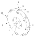
도 1은 본 발명의 실시예에 의한 밀링머신의 밀링커터의 사시도이다.
도 2는 본 발명의 실시예에 의한 밀링머신의 밀링커터의 분해사시도이다.
도 3은 본 발명의 실시예에 의한 밀링머신의 밀링커터의 후부사시도이다.
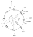
도 4는 본 발명의 실시예에 의한 밀링머신의 밀링커터의 저면도이다.
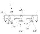
도 5는 본 발명의 실시예에 의한 밀링머신의 밀링커터의 측면도이다.
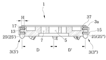
도 6은 본 발명의 실시예에 의한 밀링머신의 밀링커터의 측단면도이다.
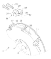
도 7은 본 발명의 다른 실시예에 의한 바이트와 바이트안착홈의 결합 사시도이다. 1 is a perspective view of a milling cutter of a milling machine according to an embodiment of the present invention.
2 is an exploded perspective view of a milling cutter of a milling machine according to an embodiment of the present invention.
3 is a rear perspective view of a milling cutter of a milling machine according to an embodiment of the present invention.
4 is a bottom view of a milling cutter of a milling machine according to an embodiment of the present invention.
5 is a side view of a milling cutter of a milling machine according to an embodiment of the present invention.
6 is a side cross-sectional view of a milling cutter of a milling machine according to an embodiment of the present invention.
7 is a combined perspective view of a byte and a byte seating groove according to another embodiment of the present invention.
이하, 첨부된 도면을 동시에 참조하여 본 발명의 구체적인 내용을 상세하게 설명한다. Hereinafter, specific contents of the present invention will be described in detail with reference to the accompanying drawings.
본 발명에 의한 밀링커터는 커터본체(1)와, 커터본체(1)에 결합되는 바이트(3)를 포함한다. 커터본체(1)는 원반 형태로 되어 있으며 중심에는 주축(S)을 끼울 수 있는 센터홀(5)이 마련되어 있다. 센터홀(5) 주변에는 커터본체(1)를 주축(S)에 메인볼트로써 고정시키기 위한 볼트체결공(7)이 마련되어 있다. The milling cutter according to the present invention includes a
복수 개의 바이트안착홈(9)이 커터본체(1)의 측면(11) 원주방향을 따라 간격을 두고 마련되어 있다. 바이트안착홈(9)은 주축(S)의 연장 방향에 대하여 소정의 각도(K)로 경사지게 연장되어 있다. 전후방향으로 개방되어 있어 레일처럼 형성되어 있는 바이트안착홈(9)을 커터본체(1)의 측면(11) 상에 마련함으로써 바이트(3)를 전후방향(즉 주축의 길이방향)으로 조정할 수 있는 기반이 마련되는 것이다. A plurality of
바이트안착홈(9)의 바닥면(13)에는 제1체결볼트(15)를 나사체결할 수 있는 탭공(17)이 마련되어 있다. 탭공(17)은 2개가 마련되어 있다. 바이트안착홈(9)과 바이트(3) 사이에는 유격이 최소한으로 존재하도록 하는 것이 바람직하다. The
막대 형태로 된 바이트(3)는 바이트안착홈(9)에 각각 안착된 상태에서 제1체결볼트(15)에 의해 고정된다. 바이트(3)는 바이트본체(19) 및 바이트본체(19)의 선단에 마련되는 절삭부(21)를 포함한다. The
절삭부(21)는 바이트본체(19)의 선단에 마련되는 인서트안착홈(23)과, 인서트안착홈(23)에 안착되어 고정되는 인서트(25)를 포함한다. 인서트(25)는 바이트의 절삭부(21)에 결합되며, 절삭날의 기능을 수행하기 위하여 커팅엣지(25a, cutting edge)를 제공한다. 인서트(25)는 통상적으로 초경으로 되어 있으며 다양한 형태로 시중에 공급되어 있다. The
인서트(25)는 인서트고정대(27)에 의해 바이트본체(19)에 고정될 수 있다. 인서트고정대(27)는 덮개와 같이 인서트(25)의 일면을 강하게 압박하여 인서트안착홈(23)에 고정되도록 한다. 인서트고정대(27)는 제2체결볼트(29)에 의해 커터본체(1)의 인서트고정대안착면(31)에 안착 고정된다. The
본 실시예에 의하면, 바이트(3)가 커터본체(1)에 설치되어 있는 상태에서 인서트를 새것으로 교체할 수 있도록 하고 있다. 이를 위하여 인서트고정대(27)를 분해하기 위한 렌치를 사용할 수 있도록 하고 분리된 인서트고정대(27)가 커터본체에서 빠질 수 있도록 인서트고정대가이드홈(33)이 마련된다. 인서트고정대가이드홈(33)은 바이트안착홈(9)에 대하여 직각 또는 그와 유사한 각도를 이루고 있다. According to this embodiment, the insert can be replaced with a new one while the
본 발명의 실시예에 의하면, 제1체결볼트(15)가 관통되는 구멍으로서 바이트본체(19)에 마련되는 볼트공(35)이 장공으로 되어 있다. 이로써 바이트(3)는 바이트안착홈(9)에 끼워진 상태에서 자신의 길이방향(L)을 따라 위치 조정이 가능하게 되는 것이다. According to the embodiment of the present invention, as the hole through which the first fastening
본 발명의 실시예에 의하면, 커터본체(1)의 배면에는 링형상으로 된 후방지지판(37)이 제3체결볼트(39)에 의해 고정 설치된다. 후방지지판(37)은 바이트안착홈(9)의 일측이 폐쇄되도록 한다. 후방지지판(37)에는 각 바이트의 후단(3a)을 지지하기 위한 스토퍼(41)가 체결된다. 스토퍼(41)는 볼트, 특히 무두볼트의 형태로 되어 있다. 스토퍼(41)는 후방지지판(37)에 나사체결되며 관통하여 바이트의 후단(3a)에 지지된다. 이 스토퍼(41)는 바이트(3)가 절삭가공을 할 때 가해지는 힘에 의해 후방으로 밀리는 것을 방지할 수 있다. 진동이나 충격으로 스토퍼(41)가 풀리는 것을 방지하기 위하여 로크너트(43, lock nut)가 스토퍼(41)에 더 결합될 수 있다. According to the embodiment of the present invention, the
이하에서는 도 4, 5, 6을 주로 참조하면서 본 발명의 다른 실시예를 설명한다. Hereinafter, another embodiment of the present invention will be described with reference mainly to FIGS. 4, 5, and 6.
본 발명의 다른 실시예에 의하면 본 발명의 밀링커터는 황삭과 정삭을 동시에 수행할 수 있도록 바이트(3)를 설치할 수 있게 한다. 즉 밀링커터의 진행방향에 대하여 선단에 위치해 있는 바이트(3')는 황삭을 하게끔 하고 후단에 있는 바이트(3")는 정삭을 하게끔 할 수 있다. 황삭을 위한 바이트(3')와 정삭을 위한 바이트(3")는 커터본체의 원주방향을 따라 교변하여 배치될 수 있다. 황삭을 위한 바이트(3')의 커터본체로부터의 돌출길이가 정삭을 위한 바이트(3")의 돌출길이보다 낮게 되어 있다. 그 높이차는 재료의 성질 등에 따라 달리 설정될 수 있다. According to another embodiment of the present invention, the milling cutter of the present invention allows the
황삭을 위한 바이트(3')가 먼저 피가공물에 저촉되어야 하므로 센터홀(5)의 중심에서 인서트(25)의 커팅엣지(25a)까지의 거리(D,D')를 서로 달리 함으로써 어느 하나의 바이트가 먼저 피가공물을 절삭하도록 되어 있다. 물론 황삭을 위한 바이트(3')가 먼저 피가공물을 절삭하며 그 후 곧바로 정삭을 위한 바이트(3")가 절삭을 하게끔 되어 있다. 그러므로 황삭을 위한 바이트(3')의 거리(D)가 정삭을 위한 바이트(3")의 거리(D') 보다 크게 되어 있다. Since the bite for roughing (3') must first hit the workpiece, the distance (D, D') from the center of the center hole (5) to the cutting edge (25a) of the insert (25) is different. The bite is intended to cut the workpiece first. Of course, the bite 3'for roughing first cuts the workpiece, and immediately thereafter the
인서트(3)의 커팅엣지(25a)와 센터홀의 중심과의 거리(D,D') 차이는 바이트안착홈(9)의 깊이(H)를 교변하면서 달리하거나 바이트안착홈의 형태를 달리 함으로써 쉽게 만들 수 있다. The difference (D, D') between the cutting edge (25a) of the insert (3) and the center of the center hole can be easily changed by changing the depth (H) of the bite seating groove (9) or by changing the shape of the bite seating groove. I can make it.
바이트본체(19)의 크기나 형태 또는 인서트(25)의 크기나 형태를 조정함으로써 황삭을 위한 것과 정삭을 위한 것으로 구분할 수도 있다. 예를 들어 황삭을 위한 인서트(25')가 정삭을 위한 인서트(25") 보다 규격이 클 수 있다. By adjusting the size or shape of the
아무튼 다양한 방법으로 바이트(3)를 조합함으로써 황삭과 정삭이 동시에 이루어지도록 할 수 있다. In any case, by combining the
이하, 도 7을 참조하여 본 발명의 다른 실시예를 설명한다. 바이트안착홈의 바닥면(13)은 평평할 수도 있지만 도 7에 도시된 바와 같이 가이드돌기(45)가 돌출될 수도 있다 바이트에는 이 가이드돌기와 암수결합하는 가이드홈(47)이 마련될 수 있다. 이들은 바이트의 안정적이고 용이한 결합을 위한 것이다. 가이드돌기(45) 보다는 가이드홈(47)의 길이가 길어 바이트(3)의 높이를 조정할 수 있게끔 구성된다. Hereinafter, another embodiment of the present invention will be described with reference to FIG. 7. The
위에 도시 및 설명된 구성은 본 발명의 기술적 사상에 근거한 바람직한 실시예에 지나지 아니한다. 당업자는 통상의 기술적 상식을 바탕으로 다양한 변경실시를 할 수 있을 것이지만 이는 본 발명의 보호범위에 포함될 수 있음을 주지해야 할 것이다. The configuration shown and described above is only a preferred embodiment based on the technical idea of the present invention. Those skilled in the art will be able to make various changes based on common technical common sense, but it should be noted that it may be included in the protection scope of the present invention.
1 : 커터본체
3 : 바이트
5 : 센터홀
9 : 바이트안착홈
13 : 바닥면
15,29,39 : 제1,2,3 체결볼트
19 : 바이트본체
21 : 절삭부
23 : 인서트안착홈
25 : 인서트
27 : 인서트고정대
31 : 인서트고정대안착면
33 : 인서트고정대가이드홈
37 : 후방지지판
41 : 스토퍼
45 : 가이드돌기
47 : 가이드홈1: cutter body 3: byte
5: Center Hall 9: Bite Seating Home
13:
19: byte body 21: cutting portion
23: insert seating groove 25: insert
27: insert holder 31: insert holder seating surface
33: insert holder guide groove 37: rear support plate
41: stopper 45: guide projection
47: Guide home
Claims (5)
상기 커터본체의 측면 원주방향을 따라 간격을 두고 마련되는 것으로서, 제1체결볼트를 나사체결할 수 있는 탭공이 마련되어 있는 복수 개의 바이트안착홈;
상기 바이트안착홈에 안착된 상태에서 제1체결볼트에 의해 고정되는 것으로서 절삭부를 제공하기 위한 막대 형태의 바이트본체;
상기 바이트본체의 절삭부에 결합되는 것으로서 절삭날의 기능을 수행하기 위하여 커팅엣지를 제공하는 인서트(insert);를 포함하는 것을 특징으로 하는 밀링머신의 밀링커터.
It is in the form of a disc, and the center is provided with a center hole for connection with the main shaft;
A plurality of bite seating grooves provided at intervals along the circumferential direction of the side of the cutter body, and provided with a tap hole for screwing the first fastening bolt;
A rod-shaped bite body for providing a cutting part as being fixed by a first fastening bolt while seated in the bite-receiving groove;
Milling cutter of the milling machine comprising a; insert (insert) to provide a cutting edge to perform the function of the cutting edge as being coupled to the cutting portion of the bite body.
상기 제1체결볼트가 관통되는 구멍으로서 상기 바이트본체에 마련된 볼트공이 장공으로 되어 있음으로써;
상기 바이트는 상기 바이트안착홈에 끼워진 상태에서 자신의 길이방향을 따라 위치 조정이 가능하게 되어 있는 것을 특징으로 하는 밀링머신의 밀링커터.
According to claim 1,
The first fastening bolt is a hole through which the bolt hole provided in the bite body is made into a long hole;
The bite is a milling cutter of a milling machine characterized in that it is possible to adjust the position along its longitudinal direction while being fitted in the bite seating groove.
상기 바이트본체에는 인서트안착홈 및 탭공이 마련되어 있으며;
상기 인서트는 제2체결볼트에 의해 체결 고정되는 인서트고정대에 의해 상기 인서트안착홈에 고정되는 것을 특징으로 하는 밀링머신의 밀링커터.
According to claim 1,
The bite body is provided with an insert seating groove and a tap hole;
The insert is a milling cutter of a milling machine characterized in that it is fixed to the insert seating groove by an insert holder that is fastened and fixed by a second fastening bolt.
상기 커터본체의 배면에는 후방지지판이 제3체결볼트에 의해 고정 설치되며;
상기 후방지지판에는 상기 바이트의 후단을 지지하기 위한 스토퍼볼트가 체결됨으로써;
상기 바이트가 절삭가공시 가해지는 힘에 의해 후방으로 밀리는 것을 방지하는 것을 특징으로 하는 밀링머신의 밀링커터.
According to claim 1,
A rear support plate is fixedly installed by a third fastening bolt on the rear surface of the cutter body;
A stopper bolt for supporting a rear end of the bite is fastened to the rear support plate;
Milling cutter of the milling machine, characterized in that to prevent the bite from being pushed backward by the force applied during cutting.
상기 센터홀의 중심에서 상기 인서트의 커팅엣지 간의 거리(D,D')가 상기 커터본체의 원주방향을 따라서 교변하면서 달리 설정되어 있음으로써;
황삭과 정삭을 동시에 수행할 수 있게 되는 것을 특징으로 하는 밀링머신의 밀링커터. According to claim 1,
By setting the distance (D, D') between the cutting edges of the insert from the center of the center hole while changing along the circumferential direction of the cutter body;
Milling cutter of the milling machine, characterized in that it is possible to perform roughing and finishing at the same time.
Priority Applications (1)
| Application Number | Priority Date | Filing Date | Title |
|---|---|---|---|
| KR1020180146054A KR102162258B1 (en) | 2018-11-23 | 2018-11-23 | Milling Cutter For Milling Machine |
Applications Claiming Priority (1)
| Application Number | Priority Date | Filing Date | Title |
|---|---|---|---|
| KR1020180146054A KR102162258B1 (en) | 2018-11-23 | 2018-11-23 | Milling Cutter For Milling Machine |
Publications (2)
| Publication Number | Publication Date |
|---|---|
| KR20200060902A true KR20200060902A (en) | 2020-06-02 |
| KR102162258B1 KR102162258B1 (en) | 2020-10-06 |
Family
ID=71090545
Family Applications (1)
| Application Number | Title | Priority Date | Filing Date |
|---|---|---|---|
| KR1020180146054A Active KR102162258B1 (en) | 2018-11-23 | 2018-11-23 | Milling Cutter For Milling Machine |
Country Status (1)
| Country | Link |
|---|---|
| KR (1) | KR102162258B1 (en) |
Cited By (6)
| Publication number | Priority date | Publication date | Assignee | Title |
|---|---|---|---|---|
| CN114406329A (en) * | 2021-12-30 | 2022-04-29 | 常州市精尔锐工具制造有限公司 | Assembled disc milling cutter with fine adjustment function |
| CN114799300A (en) * | 2022-05-11 | 2022-07-29 | 潍柴动力股份有限公司 | Milling cutter set and milling method |
| CN116275226A (en) * | 2023-05-16 | 2023-06-23 | 南通中南智能科技有限公司 | Disc milling cutter and quick blade-changing milling machine with same |
| CN117444289A (en) * | 2023-11-27 | 2024-01-26 | 中航飞机起落架有限责任公司 | A method for processing arc bottom blind keyway in hole |
| KR20240033762A (en) * | 2022-09-05 | 2024-03-13 | 김남국 | Milling Cutter For Milling Machine |
| KR102768475B1 (en) * | 2024-07-05 | 2025-02-19 | 프리텍코리아 주식회사 | Cutting apparatus for the field heating asphalt recycling packing apparatus |
Citations (6)
| Publication number | Priority date | Publication date | Assignee | Title |
|---|---|---|---|---|
| JPH07251340A (en) * | 1994-03-16 | 1995-10-03 | Shiyouun Kosakusho:Kk | Cutting tool and cutting method |
| JP2000237904A (en) * | 1999-02-22 | 2000-09-05 | Mitsubishi Materials Corp | Turning tools |
| KR20070025147A (en) | 2005-08-31 | 2007-03-08 | 삼성석유화학(주) | Solid fraction recovery method in terephthalic acid mother liquor using a separation system |
| KR100744613B1 (en) * | 2007-01-31 | 2007-08-01 | 한국교세라정공(주) | Milling cutter |
| KR20080081233A (en) | 2004-12-30 | 2008-09-09 | 엘지전자 주식회사 | Channel Information Update Method in Broadband Wireless Access System |
| KR20170072401A (en) | 2015-12-16 | 2017-06-27 | 중앙대학교 산학협력단 | IoT environmental control system |
-
2018
- 2018-11-23 KR KR1020180146054A patent/KR102162258B1/en active Active
Patent Citations (6)
| Publication number | Priority date | Publication date | Assignee | Title |
|---|---|---|---|---|
| JPH07251340A (en) * | 1994-03-16 | 1995-10-03 | Shiyouun Kosakusho:Kk | Cutting tool and cutting method |
| JP2000237904A (en) * | 1999-02-22 | 2000-09-05 | Mitsubishi Materials Corp | Turning tools |
| KR20080081233A (en) | 2004-12-30 | 2008-09-09 | 엘지전자 주식회사 | Channel Information Update Method in Broadband Wireless Access System |
| KR20070025147A (en) | 2005-08-31 | 2007-03-08 | 삼성석유화학(주) | Solid fraction recovery method in terephthalic acid mother liquor using a separation system |
| KR100744613B1 (en) * | 2007-01-31 | 2007-08-01 | 한국교세라정공(주) | Milling cutter |
| KR20170072401A (en) | 2015-12-16 | 2017-06-27 | 중앙대학교 산학협력단 | IoT environmental control system |
Cited By (8)
| Publication number | Priority date | Publication date | Assignee | Title |
|---|---|---|---|---|
| CN114406329A (en) * | 2021-12-30 | 2022-04-29 | 常州市精尔锐工具制造有限公司 | Assembled disc milling cutter with fine adjustment function |
| CN114799300A (en) * | 2022-05-11 | 2022-07-29 | 潍柴动力股份有限公司 | Milling cutter set and milling method |
| CN114799300B (en) * | 2022-05-11 | 2024-01-30 | 潍柴动力股份有限公司 | Milling cutter set and milling method |
| KR20240033762A (en) * | 2022-09-05 | 2024-03-13 | 김남국 | Milling Cutter For Milling Machine |
| CN116275226A (en) * | 2023-05-16 | 2023-06-23 | 南通中南智能科技有限公司 | Disc milling cutter and quick blade-changing milling machine with same |
| CN116275226B (en) * | 2023-05-16 | 2023-08-15 | 南通中南智能科技有限公司 | Disc type milling cutter and fast edge-changing milling machine with the disc type milling cutter |
| CN117444289A (en) * | 2023-11-27 | 2024-01-26 | 中航飞机起落架有限责任公司 | A method for processing arc bottom blind keyway in hole |
| KR102768475B1 (en) * | 2024-07-05 | 2025-02-19 | 프리텍코리아 주식회사 | Cutting apparatus for the field heating asphalt recycling packing apparatus |
Also Published As
| Publication number | Publication date |
|---|---|
| KR102162258B1 (en) | 2020-10-06 |
Similar Documents
| Publication | Publication Date | Title |
|---|---|---|
| KR20200060902A (en) | Milling Cutter For Milling Machine | |
| KR101292441B1 (en) | Tangential cutting insert | |
| JP6205726B2 (en) | Cutting inserts for face milling and exchangeable face milling | |
| KR101657730B1 (en) | Cutting tool having an adjustment mechanism | |
| JP2007062006A (en) | Bite and comb blade lathe using it | |
| KR20140020903A (en) | Cutting insert and shim for milling cutters | |
| JP2011156656A (en) | Slotting cutter with cantilevered member | |
| KR20140002604A (en) | Milling cutter having serrated cutting inserts spaced apart with varying axial offsets | |
| JP2017535439A5 (en) | Cutting inserts and tools for milling square shoulders | |
| JP4768825B2 (en) | Gear cutting tool with replaceable cutting insert | |
| JP2018527208A (en) | Tool body and turning tool for grooving | |
| JP2003512183A (en) | Cutting tool for high-speed machining | |
| US9481043B2 (en) | Tool cassette for insertion in a cassette seat and tool having a cassette seat for a tool cassette of this type | |
| US10286459B2 (en) | Machining tool | |
| US10315336B2 (en) | Drill bit | |
| US9707700B2 (en) | Tile saw | |
| JP6998946B2 (en) | Tangent cutting inserts for face milling tools and face milling tools | |
| JP2003503218A (en) | Cutting tool with direct chip mounting | |
| US1793564A (en) | Tool holder with dovetail lock | |
| US1867021A (en) | Method of producing metal working tools | |
| US1056466A (en) | Cutter-head-securing means. | |
| US751952A (en) | Rotary cutter-head | |
| US436306A (en) | Henry m | |
| US1835992A (en) | Combined post shank and bit | |
| US418366A (en) | crampton |
Legal Events
| Date | Code | Title | Description |
|---|---|---|---|
| PA0109 | Patent application |
St.27 status event code: A-0-1-A10-A12-nap-PA0109 |
|
| PA0201 | Request for examination |
St.27 status event code: A-1-2-D10-D11-exm-PA0201 |
|
| D13-X000 | Search requested |
St.27 status event code: A-1-2-D10-D13-srh-X000 |
|
| D14-X000 | Search report completed |
St.27 status event code: A-1-2-D10-D14-srh-X000 |
|
| PE0902 | Notice of grounds for rejection |
St.27 status event code: A-1-2-D10-D21-exm-PE0902 |
|
| E13-X000 | Pre-grant limitation requested |
St.27 status event code: A-2-3-E10-E13-lim-X000 |
|
| P11-X000 | Amendment of application requested |
St.27 status event code: A-2-2-P10-P11-nap-X000 |
|
| P13-X000 | Application amended |
St.27 status event code: A-2-2-P10-P13-nap-X000 |
|
| PG1501 | Laying open of application |
St.27 status event code: A-1-1-Q10-Q12-nap-PG1501 |
|
| E701 | Decision to grant or registration of patent right | ||
| PE0701 | Decision of registration |
St.27 status event code: A-1-2-D10-D22-exm-PE0701 |
|
| GRNT | Written decision to grant | ||
| PR0701 | Registration of establishment |
St.27 status event code: A-2-4-F10-F11-exm-PR0701 |
|
| PR1002 | Payment of registration fee |
St.27 status event code: A-2-2-U10-U11-oth-PR1002 Fee payment year number: 1 |
|
| PG1601 | Publication of registration |
St.27 status event code: A-4-4-Q10-Q13-nap-PG1601 |
|
| R18-X000 | Changes to party contact information recorded |
St.27 status event code: A-5-5-R10-R18-oth-X000 |
|
| P14-X000 | Amendment of ip right document requested |
St.27 status event code: A-5-5-P10-P14-nap-X000 |
|
| PN2301 | Change of applicant |
St.27 status event code: A-5-5-R10-R11-asn-PN2301 |
|
| P16-X000 | Ip right document amended |
St.27 status event code: A-5-5-P10-P16-nap-X000 |
|
| PN2301 | Change of applicant |
St.27 status event code: A-5-5-R10-R14-asn-PN2301 |
|
| P22-X000 | Classification modified |
St.27 status event code: A-4-4-P10-P22-nap-X000 |
|
| PR1001 | Payment of annual fee |
St.27 status event code: A-4-4-U10-U11-oth-PR1001 Fee payment year number: 4 |
|
| P22-X000 | Classification modified |
St.27 status event code: A-4-4-P10-P22-nap-X000 |
|
| PR1001 | Payment of annual fee |
St.27 status event code: A-4-4-U10-U11-oth-PR1001 Fee payment year number: 5 |
|
| PR1001 | Payment of annual fee |
St.27 status event code: A-4-4-U10-U11-oth-PR1001 Fee payment year number: 6 |
|
| U11 | Full renewal or maintenance fee paid |
Free format text: ST27 STATUS EVENT CODE: A-4-4-U10-U11-OTH-PR1001 (AS PROVIDED BY THE NATIONAL OFFICE) Year of fee payment: 6 |