KR20200071473A - Lamp for vehicle - Google Patents
Lamp for vehicle Download PDFInfo
- Publication number
- KR20200071473A KR20200071473A KR1020180159238A KR20180159238A KR20200071473A KR 20200071473 A KR20200071473 A KR 20200071473A KR 1020180159238 A KR1020180159238 A KR 1020180159238A KR 20180159238 A KR20180159238 A KR 20180159238A KR 20200071473 A KR20200071473 A KR 20200071473A
- Authority
- KR
- South Korea
- Prior art keywords
- lens
- focus
- vehicle
- vehicle lamp
- light source
- Prior art date
- Legal status (The legal status is an assumption and is not a legal conclusion. Google has not performed a legal analysis and makes no representation as to the accuracy of the status listed.)
- Ceased
Links
- 230000003287 optical effect Effects 0.000 claims description 12
- 238000000034 method Methods 0.000 claims description 4
- 230000001678 irradiating effect Effects 0.000 claims description 3
- 230000003044 adaptive effect Effects 0.000 description 9
- 230000004313 glare Effects 0.000 description 7
- 238000004519 manufacturing process Methods 0.000 description 7
- 230000000694 effects Effects 0.000 description 5
- XUIMIQQOPSSXEZ-UHFFFAOYSA-N Silicon Chemical compound [Si] XUIMIQQOPSSXEZ-UHFFFAOYSA-N 0.000 description 4
- 230000004075 alteration Effects 0.000 description 4
- 230000007261 regionalization Effects 0.000 description 4
- 229910052710 silicon Inorganic materials 0.000 description 4
- 239000010703 silicon Substances 0.000 description 4
- 238000010586 diagram Methods 0.000 description 3
- 230000006870 function Effects 0.000 description 3
- 230000001976 improved effect Effects 0.000 description 3
- 238000005516 engineering process Methods 0.000 description 2
- 238000009434 installation Methods 0.000 description 2
- 239000011159 matrix material Substances 0.000 description 2
- 230000009131 signaling function Effects 0.000 description 2
- OAICVXFJPJFONN-UHFFFAOYSA-N Phosphorus Chemical compound [P] OAICVXFJPJFONN-UHFFFAOYSA-N 0.000 description 1
- 238000005260 corrosion Methods 0.000 description 1
- 230000007797 corrosion Effects 0.000 description 1
- 230000004438 eyesight Effects 0.000 description 1
- 238000005286 illumination Methods 0.000 description 1
- 239000004065 semiconductor Substances 0.000 description 1
- 238000004381 surface treatment Methods 0.000 description 1
Images




Classifications
-
- F—MECHANICAL ENGINEERING; LIGHTING; HEATING; WEAPONS; BLASTING
- F21—LIGHTING
- F21S—NON-PORTABLE LIGHTING DEVICES; SYSTEMS THEREOF; VEHICLE LIGHTING DEVICES SPECIALLY ADAPTED FOR VEHICLE EXTERIORS
- F21S41/00—Illuminating devices specially adapted for vehicle exteriors, e.g. headlamps
- F21S41/10—Illuminating devices specially adapted for vehicle exteriors, e.g. headlamps characterised by the light source
- F21S41/14—Illuminating devices specially adapted for vehicle exteriors, e.g. headlamps characterised by the light source characterised by the type of light source
- F21S41/141—Light emitting diodes [LED]
- F21S41/151—Light emitting diodes [LED] arranged in one or more lines
-
- F—MECHANICAL ENGINEERING; LIGHTING; HEATING; WEAPONS; BLASTING
- F21—LIGHTING
- F21S—NON-PORTABLE LIGHTING DEVICES; SYSTEMS THEREOF; VEHICLE LIGHTING DEVICES SPECIALLY ADAPTED FOR VEHICLE EXTERIORS
- F21S41/00—Illuminating devices specially adapted for vehicle exteriors, e.g. headlamps
- F21S41/20—Illuminating devices specially adapted for vehicle exteriors, e.g. headlamps characterised by refractors, transparent cover plates, light guides or filters
- F21S41/25—Projection lenses
-
- F—MECHANICAL ENGINEERING; LIGHTING; HEATING; WEAPONS; BLASTING
- F21—LIGHTING
- F21W—INDEXING SCHEME ASSOCIATED WITH SUBCLASSES F21K, F21L, F21S and F21V, RELATING TO USES OR APPLICATIONS OF LIGHTING DEVICES OR SYSTEMS
- F21W2102/00—Exterior vehicle lighting devices for illuminating purposes
- F21W2102/10—Arrangement or contour of the emitted light
- F21W2102/13—Arrangement or contour of the emitted light for high-beam region or low-beam region
- F21W2102/135—Arrangement or contour of the emitted light for high-beam region or low-beam region the light having cut-off lines, i.e. clear borderlines between emitted regions and dark regions
- F21W2102/14—Arrangement or contour of the emitted light for high-beam region or low-beam region the light having cut-off lines, i.e. clear borderlines between emitted regions and dark regions having vertical cut-off lines; specially adapted for adaptive high beams, i.e. wherein the beam is broader but avoids glaring other road users
- F21W2102/145—Arrangement or contour of the emitted light for high-beam region or low-beam region the light having cut-off lines, i.e. clear borderlines between emitted regions and dark regions having vertical cut-off lines; specially adapted for adaptive high beams, i.e. wherein the beam is broader but avoids glaring other road users wherein the light is emitted between two parallel vertical cutoff lines, e.g. selectively emitted rectangular-shaped high beam
Landscapes
- Engineering & Computer Science (AREA)
- General Engineering & Computer Science (AREA)
- Physics & Mathematics (AREA)
- Microelectronics & Electronic Packaging (AREA)
- Optics & Photonics (AREA)
- Non-Portable Lighting Devices Or Systems Thereof (AREA)
Abstract
본 발명은 차량용 램프에 대한 것으로, 본 발명의 일 실시예에 따른 차량용 램프는 복수의 광원을 포함하는 광원부; 및 상기 광원부에서 방출된 광을 차량 외부로 조사하여 빔 패턴을 형성하는 렌즈를 포함하고, 상기 렌즈는, 제1 초점 및 제2 초점을 포함하여 형성되되, 상기 제1 초점은 상기 렌즈의 외부에 위치하고, 상기 제2 초점은 상기 렌즈의 내부에 위치한다.The present invention relates to a vehicle lamp, the vehicle lamp according to an embodiment of the present invention includes a light source unit including a plurality of light sources; And a lens that irradiates light emitted from the light source unit to the outside of the vehicle to form a beam pattern, and the lens is formed to include a first focus and a second focus, wherein the first focus is outside the lens. And the second focal point is located inside the lens.
Description
본 발명은 차량용 램프에 관한 것이다. 구체적으로, 본 발명은 단일 렌즈를 통해 빔 패턴을 제공하는 차량용 적응형 헤드 램프에 대한 것이다.The present invention relates to a vehicle lamp. Specifically, the present invention relates to an adaptive headlamp for a vehicle that provides a beam pattern through a single lens.
일반적으로, 차량은 야간 주행 시에 차량 주변에 위치한 대상물을 용이하게 확인하기 위한 조명 기능 및 다른 차량이나 도로 이용자들에게 차량의 주행 상태를 알리기 위한 신호 기능을 가지는 다양한 종류를 램프를 구비하고 있다.In general, a vehicle is equipped with various types of lamps having a lighting function for easily identifying an object located around the vehicle during night driving and a signal function for informing the driving condition of the vehicle to other vehicles or road users.
예를 들어, 주로 조명 기능 기능을 목적으로 하는 헤드 램프(Head lamp) 및 포그 램프(Fog lamp)와, 신호 기능을 목적으로 하는 턴 시그널 램프(Turn signal lamp), 테일 램프(Tail lamp), 브레이크 램프(Brake lamp), 사이드 마커(Side Marker) 등을 구비하고 있으며, 이러한 차량용 램프는 각 기능을 충분히 발휘하도록 그 설치 기준과 규격에 대해서 법규로 규정되어 있다.For example, head lamps and fog lamps primarily intended for lighting functions, and turn signal lamps, tail lamps, and brakes intended for signal functions. Brake lamps, side markers, etc. are provided, and such installation lamps and regulations are prescribed in the regulations for the installation standards and specifications to sufficiently exhibit each function.
차량용 램프들 중, 헤드 램프는 야간과 같이 주변 환경이 어두운 상황에서 차량을 주행하는 경우, 운전자의 전방 시야가 확보되도록 로우 빔 패턴이나 하이 빔 패턴을 형성하는 것으로서, 안전 운행을 하는데 있어 매우 중요한 역할을 하고 있다.Among the vehicle lamps, the head lamp forms a low beam pattern or a high beam pattern to ensure a driver's front view when driving a vehicle in a dark environment such as at night, and plays a very important role in safe driving. Is doing.
이러한 헤드 램프는, 반대 방향으로 주행하는 대향 차량의 운전자 또는 선행 차량 운전자에게 눈부심 유발을 예방하도록 평상 시에는 주로 로우 빔 패턴을 유지하고, 고속 주행 시 또는 주변 밝기가 어두운 곳을 운행하는 경우에는 필요에 따라 하이 빔 패턴을 형성하여 안전운전을 도모하도록 하고 있다.Such a headlamp maintains a low beam pattern mainly during normal driving to prevent glare from a driver of an opposing vehicle or a preceding vehicle driving in the opposite direction, and is necessary when driving at high speed or when driving in a dark environment. According to this, a high beam pattern is formed to promote safe driving.
그런데, 대향 차량 또는 선행 차량을 인지하지 못한 상태에서 하이 빔 패턴을 형성하고 주행하는 경우가 있으며, 이의 경우 대향 차량 운전자 또는 선행 차량 운전자에게 눈부심을 유발시킴으로써, 안전사고의 우려가 큰 문제점이 있다.However, there is a case in which a high beam pattern is formed and driven in a state in which the opposing vehicle or the preceding vehicle is not recognized, and in this case, there is a great problem of a safety accident by causing glare to the opposing vehicle driver or the preceding vehicle driver.
이에, 최근에는 하이 빔 패턴을 형성한 상태로 주행 중에, 대향 차량 또는 선행 차량이 감지되면, 램프의 광 조명 각도, 밝기, 폭 및 길이 등을 자동으로 조정함으로써, 대향 차량 또는 선행 차량 운전자에게 눈부심을 유발시키지 않도록 하는 ADB(Adaptive Driving Beam) 헤드 램프, 즉 적응형 헤드 램프가 제공되고 있다.Accordingly, recently, when a vehicle or a vehicle ahead is detected while driving in a state in which a high beam pattern is formed, the light illumination angle, brightness, width, and length of the lamp are automatically adjusted to glare to the vehicle or vehicle driver. Adaptive driving beam (ADB) headlamps, ie, adaptive headlamps, are provided that do not cause them.
적응형 헤드 램프는, 대향 차량 또는 선행 차량이 감지되는 경우 스위블 액츄에이터에 의해 램프 각도를 변경시킴으로써, 대향 차량 또는 선행 차량이 위치하는 공간에 암영대(Dark zone)가 형성되도록 하는 다이내믹 타입(Dynamic type)과, 복수의 광원들을 선택적으로 점등 또는 소등시킴으로써, 대향 차량 또는 선행 차량이 위치하는 공간에 암영대가 형성되도록 하는 매트릭스 타입(Matrix type)으로 구분된다.The adaptive headlamp is a dynamic type that allows a dark zone to be formed in a space where the opposing vehicle or the preceding vehicle is located by changing the lamp angle by a swivel actuator when the opposing vehicle or the preceding vehicle is detected. ) And by selectively turning on or off a plurality of light sources, a dark zone is formed in a space in which the opposing vehicle or the preceding vehicle is located.
한편, 적응형 헤드 램프는 일반적으로 복수의 광원들에서 방출된 광을 복수의 렌즈를 순차적으로 통과시켜 차량 외부로 조사하여 빔 패턴을 형성한다.On the other hand, an adaptive head lamp generally forms a beam pattern by irradiating light emitted from a plurality of light sources sequentially through a plurality of lenses to the outside of a vehicle.
따라서, 종래 기술에 따른 적응형 헤드 램프는 램프 내 공간 활용 측면에서 제약이 따르는 문제점이 있다. 또한, 종래 기술에 따른 적응형 헤드 램프는 복수의 렌즈를 사용하므로 제조 단가 면에서도 단점이 있다.Therefore, the adaptive head lamp according to the prior art has a problem in that it is limited in terms of space utilization in the lamp. In addition, the adaptive head lamp according to the prior art has a disadvantage in terms of manufacturing cost because it uses a plurality of lenses.
본 발명은 단일 렌즈를 통해 빔 패턴을 형성하는 적응형 헤드 램프를 제공하는 데 목적이 있다.An object of the present invention is to provide an adaptive headlamp that forms a beam pattern through a single lens.
본 발명의 과제들은 이상에서 언급한 과제로 제한되지 않으며, 언급되지 않은 또 다른 과제들은 아래의 기재로부터 당업자에게 명확하게 이해될 수 있을 것이다.The problems of the present invention are not limited to the problems mentioned above, and other problems not mentioned will be clearly understood by those skilled in the art from the following description.
본 발명의 일 실시예에 따른 차량용 램프는 복수의 광원을 포함하는 광원부; 및 상기 광원부에서 방출된 광을 차량 외부로 조사하여 빔 패턴을 형성하는 렌즈를 포함하고, 상기 렌즈는, 제1 초점 및 제2 초점을 포함하여 형성되되, 상기 제1 초점은 상기 렌즈의 외부에 위치하고, 상기 제2 초점은 상기 렌즈의 내부에 위치한다.A vehicle lamp according to an embodiment of the present invention includes a light source unit including a plurality of light sources; And a lens that irradiates light emitted from the light source unit to the outside of the vehicle to form a beam pattern, and the lens is formed to include a first focus and a second focus, wherein the first focus is outside the lens. And the second focal point is located inside the lens.
일 실시예에 있어서, 상기 광원부에 포함된 복수의 광원 중 적어도 하나의 광원은 상기 제1 초점상에 위치할 수 있다.In one embodiment, at least one light source among the plurality of light sources included in the light source unit may be positioned on the first focus.
일 실시예에 있어서, 상기 렌즈는 광이 입사되는 입사부, 광이 출사되는 출사부 및 상기 입사부로 입사되는 광을 상기 출사부로 안내하는 가이드부를 포함할 수 있다.In one embodiment, the lens may include an incident portion to which light is incident, an emitting portion to which light is emitted, and a guide portion to guide light incident to the incident portion to the emitting portion.
일 실시예에 있어서, 상기 제1 초점은 상기 입사부의 후방에 위치할 수 있다.In one embodiment, the first focus may be located behind the incident portion.
일 실시예에 있어서, 상기 제2 초점은 상기 가이드부의 내부에 위치할 수 있다.In one embodiment, the second focus may be located inside the guide portion.
일 실시예에 있어서, 상기 렌즈는 수평 방향 곡률과 수직 방향 곡률이 상이하게 형성될 수 있다.In one embodiment, the lens may have a horizontal curvature and a vertical curvature differently.
일 실시예에 있어서, 상기 렌즈는 상기 수평 방향 곡률이 상기 수직 방향 곡률보다 작도록 형성될 수 있다.In one embodiment, the lens may be formed such that the horizontal curvature is smaller than the vertical curvature.
일 실시예에 있어서, 상기 제1 초점 및 상기 제2 초점은 상기 빔 패턴 중 고조도 영역을 형성하는 광원의 광축상에 위치할 수 있다.In one embodiment, the first focus and the second focus may be located on an optical axis of a light source forming a high illuminance region of the beam pattern.
일 실시예에 있어서, 상기 제1 초점은 상기 렌즈에서 수평 방향으로 곡률을 형성하는 부분의 초점일 수 있다.In one embodiment, the first focus may be a focus of a portion forming a curvature in the horizontal direction in the lens.
일 실시예에 있어서, 상기 제2 초점은 상기 렌즈에서 수직 방향으로 곡률을 형성하는 부분의 초점일 수 있다.In one embodiment, the second focus may be a focus of a portion forming a curvature in the vertical direction in the lens.
본 발명은 단일 렌즈를 통해 빔 패턴을 형성하므로, 램프 내부의 공간 활용성을 향상시키는 효과가 있다.Since the present invention forms a beam pattern through a single lens, there is an effect of improving the space utilization inside the lamp.
또한, 본 발명은 단일 렌즈를 통해 빔 패턴을 형성하므로, 복수의 렌즈를 적용하는 경우보다 제조 단가가 절감되는 효과가 있다.In addition, since the present invention forms a beam pattern through a single lens, the manufacturing cost is reduced compared to the case of applying a plurality of lenses.
또한, 본 발명은 단일 렌즈를 통해 빔 패턴을 형성하므로, 광원부와 렌즈가 밀접한 거리를 유지하여 광효율이 향상되는 효과가 있다.In addition, since the present invention forms a beam pattern through a single lens, the light efficiency is improved by maintaining a close distance between the light source unit and the lens.
본 발명에 따른 효과는 이상에서 예시된 내용에 의해 제한되지 않으며, 더욱 다양한 효과들이 본 명세서 내에 포함되어 있다.The effects according to the present invention are not limited by the contents exemplified above, and more various effects are included in the present specification.
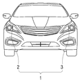
도 1은 본 발명의 일 실시예에 따른 차량용 램프가 차량에 장착된 것을 도시한 도면이다.
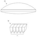
도 2는 종래 기술에 따른 차량용 램프의 구성도이다.
도 3은 본 발명의 일 실시예에 따른 차량용 램프가 형성하는 빔 패턴을 도시한 도면이다.
도 4는 본 발명의 일 실시예에 따른 차량용 램프의 사시도이다.
도 5는 본 발명의 일 실시예에 따른 차량용 램프의 평면도이다.
도 6은 본 발명의 일 실시예에 따른 차량용 램프의 측면도이다.
도 7은 본 발명의 일 실시예에 따른 차량용 램프의 일 구성인 렌즈의 제1 초점을 통해 형성되는 광 경로를 도시한 도면이다.
도 8은 본 발명의 일 실시예에 따른 차량용 램프의 일 구성인 렌즈의 제2 초점을 통해 형성되는 광 경로를 도시한 도면이다.1 is a view showing that a vehicle lamp according to an embodiment of the present invention is mounted on a vehicle.
2 is a configuration diagram of a vehicle lamp according to the prior art.
3 is a view illustrating a beam pattern formed by a vehicle lamp according to an embodiment of the present invention.
4 is a perspective view of a vehicle lamp according to an embodiment of the present invention.
5 is a plan view of a vehicle lamp according to an embodiment of the present invention.
6 is a side view of a vehicle lamp according to an embodiment of the present invention.
7 is a view showing an optical path formed through a first focus of a lens which is one component of a vehicle lamp according to an embodiment of the present invention.
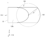
8 is a view illustrating an optical path formed through a second focus of a lens, which is one component of a vehicle lamp according to an embodiment of the present invention.
본 발명의 이점 및 특징, 그리고 그것들을 달성하는 방법은 첨부되는 도면과 함께 상세하게 후술되어 있는 실시예들을 참조하면 명확해질 것이다. 그러나 본 발명은 이하에서 개시되는 실시예들에 한정되는 것이 아니라 서로 다른 다양한 형태로 구현될 수 있으며, 단지 본 실시예들은 본 발명의 개시가 완전하도록 하고, 본 발명이 속하는 기술분야에서 통상의 지식을 가진 자에게 발명의 범주를 완전하게 알려주기 위해 제공되는 것이며, 본 발명은 청구항의 범주에 의해 정의될 뿐이다. 명세서 전체에 걸쳐 동일 참조 부호는 동일 구성 요소를 지칭한다.Advantages and features of the present invention, and methods for achieving them will be clarified with reference to embodiments described below in detail together with the accompanying drawings. However, the present invention is not limited to the embodiments disclosed below, but may be implemented in various different forms, and only the embodiments allow the disclosure of the present invention to be complete, and common knowledge in the technical field to which the present invention pertains. It is provided to completely inform the person having the scope of the invention, and the present invention is only defined by the scope of the claims. The same reference numerals refer to the same components throughout the specification.
따라서, 몇몇 실시예에서, 잘 알려진 공정 단계들, 잘 알려진 구조 및 잘 알려진 기술들은 본 발명이 모호하게 해석되는 것을 피하기 위하여 구체적으로 설명되지 않는다.Thus, in some embodiments, well-known process steps, well-known structures, and well-known techniques are not specifically described to avoid obscuring the present invention.
본 명세서에서 사용된 용어는 실시예들을 설명하기 위한 것이며 본 발명을 제한하고자 하는 것은 아니다. 본 명세서에서, 단수형은 문구에서 특별히 언급하지 않는 한 복수형도 포함한다. 명세서에서 사용되는 포함한다(comprises) 및/또는 포함하는(comprising)은 언급된 구성요소, 단계, 동작 및/또는 소자 이외의 하나 이상의 다른 구성요소, 단계, 동작 및/또는 소자의 존재 또는 추가를 배제하지 않는 의미로 사용한다. 그리고, "및/또는"은 언급된 아이템들의 각각 및 하나 이상의 모든 조합을 포함한다.The terminology used herein is for describing the embodiments and is not intended to limit the present invention. In the present specification, the singular form also includes the plural form unless otherwise specified in the phrase. Includes and/or comprising as used herein refers to the presence or addition of one or more other components, steps, operations and/or elements other than the components, steps, operations and/or elements mentioned. It is used not to exclude. And, “and/or” includes each and every combination of one or more of the mentioned items.
또한, 본 명세서에서 기술하는 실시예들은 본 발명의 이상적인 예시도인 단면도 및/또는 개략도들을 참고하여 설명될 것이다. 따라서, 제조 기술 및/또는 허용 오차 등에 의해 예시도의 형태가 변형될 수 있다. 따라서, 본 발명의 실시예들은 도시된 특정 형태로 제한되는 것이 아니라 제조 공정에 따라 생성되는 형태의 변화도 포함하는 것이다. 또한 본 발명에 도시된 각 도면에 있어서 각 구성 요소들은 설명의 편의를 고려하여 다소 확대 또는 축소되어 도시된 것일 수 있다. 명세서 전체에 걸쳐 동일 참조 부호는 동일 구성 요소를 지칭한다.In addition, the embodiments described herein will be described with reference to cross-sectional views and/or schematic drawings, which are ideal exemplary views of the present invention. Therefore, the shape of the exemplary diagram may be modified by manufacturing technology and/or tolerance. Accordingly, the embodiments of the present invention are not limited to the specific shapes shown, but also include changes in shapes generated according to the manufacturing process. In addition, in each of the drawings shown in the present invention, each component may be slightly enlarged or reduced in view of convenience of description. The same reference numerals refer to the same components throughout the specification.
이하, 본 발명에 따른 차량용 램프에 대한 바람직한 실시 예를 첨부된 예시도면에 의거하여 상세히 설명한다.Hereinafter, preferred embodiments of the vehicle lamp according to the present invention will be described in detail based on the attached exemplary drawings.
도 1은 본 발명의 일 실시예에 따른 차량용 램프가 차량에 장착된 것을 도시한 도면이다.1 is a view showing that a vehicle lamp according to an embodiment of the present invention is mounted on a vehicle.
도 1을 참조하면, 차량용 램프(1)는 우측 램프(2) 및 좌측 램프(3)를 포함하고, 본 발명에서 우측 램프(2) 및 좌측 램프(3)는 차량 전방 양측에 각각 설치되어 헤드 램프의 용도에 적합한 광을 발생시킬 수 있다.Referring to FIG. 1, the
이하, 본 발명의 실시예에서 우측 램프(2)는 차량의 전방을 기준으로 우측에 설치되는 램프를 의미하며, 좌측 램프(3)는 차량의 전방을 기준으로 좌측에 설치되는 램프를 의미하는 경우를 전제하여 설명하기로 한다.Hereinafter, in the embodiment of the present invention, the
이때, 우측 램프(2)와 좌측 램프(3)에 각각 장착되는 차량용 램프(1)의 구성은 동일하므로, 이하에서는, 우측 램프(2)에 장착된 구성만을 도시하여 설명한다.At this time, since the configuration of the
또한, 본 발명의 일 실시예에 따른 차량용 램프(1)는 차량의 주행 중 운전자가 원거리 시야를 확보하기 위하여 로우 빔 패턴과 함께 하이 빔 패턴을 동시에 형성할 수 있으나, 이하에서는 본 발명의 일 실시예에 따른 차량용 램프(1)가 하이 빔 패턴을 형성하는 경우를 예를 들어 설명하기로 한다.In addition, the
한편, 본 발명의 일 실시예에 따른 차량용 램프(1)는 차량이 야간에 주행하거나 터널 등과 같은 어두운 장소를 주행하는 경우 차량의 주행 방향으로 광을 조사하여 차량의 전방 시야가 확보될 수 있도록 하는 헤드 램프의 용도로 사용되는 경우를 예를 들어 설명하기로 한다. 특히, 본 발명의 일 실시예에 따른 차량용 램프(1)는 ADB(Adaptive Driving Beam) 타입의 헤드 램프인 것을 예를 들어 설명하기로 한다.On the other hand, the vehicle lamp (1) according to an embodiment of the present invention to ensure that the front view of the vehicle can be secured by irradiating light in the driving direction of the vehicle when the vehicle is driving at night or in a dark place such as a tunnel. A case in which the headlamp is used will be described as an example. In particular, it will be described, for example, that the
이때, ADB 타입의 헤드 램프는, 주행 중 대향 차량 또는 선행 차량이 감지되는 경우, 스위블 액츄에이터에 의해 램프 각도를 변경시킴으로써, 대향 차량 또는 선행 차량이 위치하는 공간에 암영대(Dark zone)가 형성되도록 하는 다이내믹 타입(Dynamic type)과, 복수의 광원들을 선택적으로 점등 또는 소등시킴으로써, 대향 차량 또는 선행 차량이 위치하는 공간에 암영대가 형성되도록 하는 매트릭스 타입(Matrix type)으로 구분될 수 있다.At this time, the head lamp of the ADB type, when an opposing vehicle or a preceding vehicle is detected while driving, by changing the ramp angle by a swivel actuator, a dark zone is formed in a space where the opposing vehicle or the preceding vehicle is located It can be divided into a dynamic type (Dynamic type), and a matrix type (Matrix type) to form a dark zone in the space where the opposing vehicle or the preceding vehicle is located by selectively turning on or off a plurality of light sources.
종래의 ADB 타입의 헤드 램프는 복수의 광원 및 단일 비구면 렌즈만을 이용하여 빔 패턴을 형성하였다. 이 경우, 복수의 광원 각각에서 형성된 빔 패턴 간에는 갭(gap)이 존재하였다. 따라서, 종래의 ADB 타입의 헤드 램프는 빔 패턴 간의 갭(gap)을 개선하기 위해 복수의 광원과 비구면 렌즈 사이에 실리콘 렌즈를 배치하여 빔 패턴을 형성하기에 이르렀다.The conventional ADB type head lamp forms a beam pattern using only a plurality of light sources and a single aspherical lens. In this case, a gap existed between beam patterns formed in each of the plurality of light sources. Therefore, a conventional ADB type head lamp has formed a beam pattern by arranging a silicon lens between a plurality of light sources and an aspherical lens in order to improve a gap between beam patterns.
다만, 주행 중 대향 차량 또는 선행 차량의 상하 범위보다 좌우 범위를 구분하는 것이 용이하므로, 종래의 ADB 타입의 헤드 램프는 빔 패턴 형성시 좌우 범위가 상하 범위보다 넓게 설정되도록 도 2과 같은 형태로 램프를 제작하게 되었다.However, since it is easy to distinguish the left and right ranges from the upper and lower ranges of the opposing vehicle or the preceding vehicle during driving, the conventional ADB type head lamps are formed in the form of FIG. 2 so that the left and right ranges are set wider than the upper and lower ranges when forming a beam pattern It was produced.
도 2는 종래 기술에 따른 차량용 램프의 구성도이다.2 is a configuration diagram of a vehicle lamp according to the prior art.
도 2를 참조하면, 종래 기술에 따른 차량용 램프(10)는 광원부(11), 실리콘 렌즈(12) 및 비구면 렌즈(13)를 포함한다.2, the vehicle lamp 10 according to the prior art includes a
종래 기술에 따른 차량용 램프(10)는 광원부(11)에서 방출된 광이 실리콘 렌즈(12)를 거쳐 집광되도록 하고, 실리콘 렌즈(12)에서 출사된 광이 비구면 렌즈(13)를 거쳐 차량 외부로 조사되도록 하여 도 3과 같은 빔 패턴을 형성한다.The vehicle lamp 10 according to the prior art allows light emitted from the
구체적으로, 종래 기술에 따른 차량용 램프(10)는 복수의 분할 빔 패턴(B11 ~ B16)을 포함하는 제1 빔 패턴(P1)을 형성한다.Specifically, the vehicle lamp 10 according to the prior art forms a first beam pattern P1 including a plurality of split beam patterns B11 to B16.
즉, 종래 기술에 따른 차량용 램프(10)는 빔 패턴을 형성하기 위해 복수의 렌즈를 사용한다. 따라서, 종래 기술에 따른 차량용 램프(10)는 램프 내 공간 활용 측면에서 제약이 따르는 문제점이 있다. 또한, 종래 기술에 따른 차량용 램프(10)는 복수의 렌즈를 사용하므로 제조 단가 면에서도 단점이 있다. 나아가, 종래 기술에 따른 차량용 램프(10)는 광원부(11)와 제2 렌즈(13) 사이의 갭(gap)이 존재하여 광 손실이 발생하는 문제점도 있다That is, the vehicle lamp 10 according to the prior art uses a plurality of lenses to form a beam pattern. Therefore, the vehicle lamp 10 according to the related art has a problem in that it is limited in terms of space utilization in the lamp. In addition, the vehicle lamp 10 according to the prior art uses a plurality of lenses, and thus has a disadvantage in terms of manufacturing cost. Furthermore, the vehicle lamp 10 according to the related art has a problem that light loss occurs due to a gap between the
이에 따라, 램프내 공간 활용성을 향상시키고, 제조 단가를 낮추며, 광효율을 향상시킬 수 있는 램프의 필요성이 대두된다.Accordingly, there is a need for a lamp that can improve space utilization in the lamp, lower manufacturing cost, and improve light efficiency.
도 4는 본 발명의 일 실시예에 따른 차량용 램프의 사시도이고, 도 5는 본 발명의 일 실시예에 따른 차량용 램프의 평면도이며, 도 6은 본 발명의 일 실시예에 따른 차량용 램프의 측면도이다.4 is a perspective view of a vehicle lamp according to an embodiment of the present invention, FIG. 5 is a plan view of a vehicle lamp according to an embodiment of the present invention, and FIG. 6 is a side view of a vehicle lamp according to an embodiment of the present invention .
도 4 내지 도 6을 참조하면, 본 발명의 일 실시예에 따른 차량용 램프(1)는 광원부(110) 및 렌즈(120)를 포함한다.4 to 6, the
광원부(110)는 복수의 광원을 포함한다. 도 4 내지 도 6을 참조하면, 광원부(110)는 렌즈(120)의 x축 기준으로 후방에 배치된다. 이때, 도 4 내지 도 6에서는 광원부(110)에 포함된 광원의 개수가 5개로 도시되었으나, 이는 예시이며, 차량용 램프(1)의 설계에 따라 달라질 수 있다.The
한편, 광원부(110)에 포함된 복수의 광원은 통전 신호에 의해 광을 출사시키는 것으로서, 반도체 발광 소자인 LED(Light Emitting Diode)가 적용되는 것이 바람직하나, 이에 한정되는 것은 아니며 경우에 따라서 벌브(Bulb), 레이저 등과 같은 다양한 종류의 광원이 적용될 수 있다.Meanwhile, the plurality of light sources included in the
렌즈(120)는 광원부(110)에서 방출된 광을 차량 외부로 조사하여 도 3에 도시된 바와 같은 빔 패턴을 형성한다.The
렌즈(120)는 입사부(121), 가이드부(123) 및 출사부(125)를 포함한다.The
입사부(121)는 광원부(110)에서 출사된 광이 입사된다.The light emitted from the
가이드부(123)는 입사부(121)로 입사되는 광을 출사부(125)로 안내한다.The
출사부(125)는 가이드부(123)에서 안내된 광이 출사된다.The light guided by the
즉, 본 발명의 일 실시예에 따른 차량용 램프(1)는 광원부(110)에서 방출된 광이 렌즈(120)의 입사부(121), 가이드부(123) 및 출사부(125)를 순차적으로 거쳐 외부로 조사되어 도 3에 도시된 바와 같은 빔 패턴을 형성한다.That is, in the
한편, 렌즈(120)는 수평 방향 곡률과 수직 방향 곡률이 상이하게 형성된다. 구체적으로, 렌즈(120)는 도 4 내지 도 6에 도시된 바와 같이 출사부(125) 측의 수평 방향(x축 방향) 곡률이 출사부(125) 측의 수직 방향(z축 방향) 곡률보다 작도록 형성된다. 또는, 렌즈(120)는 도 4 내지 도 6에 도시된 바와 같이 출사부(125) 측의 수평 방향(x축 방향) 곡률 반지름(r1)이 출사부(125) 측의 수직 방향(z축 방향) 곡률 반지름(r2)보다 크도록 형성된다. 즉, 렌즈(120)는 도 4 내지 도 6에 도시된 바와 같이 출사부(125) 측의 수평 방향(x축 방향) 곡률이 출사부(125) 측의 수직 방향(z축 방향) 곡률보다 완만하도록 형성된다.Meanwhile, the
또한, 도 4 내지 도 6에 도시된 바와 같이 출사부(125) 측의 수평 방향(x축 방향) 곡률이 출사부(125) 측의 수직 방향(z축 방향) 곡률보다 작도록 형성되고, 출사부(125)와 가이드부(123)는 일체로 연결되므로, 가이드부(123) 측의 수평 방향(x축 방향) 곡률도 가이드부(123) 측의 수직 방향(z축 방향) 곡률보다 작도록 형성된다. 즉, 가이드부(123)의 수평면(123a)이 수직면(123b)보다 완만하게 형성된다.In addition, as illustrated in FIGS. 4 to 6, the horizontal direction (x-axis direction) curvature of the
반면, 도 4 내지 도 6에 도시된 바와 같이 입사부(121)는 곡률이 없는 평평한 면 형태로 형성된다.On the other hand, as shown in Figures 4 to 6, the
도 7은 본 발명의 일 실시예에 따른 차량용 램프의 일 구성인 렌즈의 제1 초점을 통해 형성되는 광 경로를 도시한 도면이고, 도 10은 본 발명의 일 실시예에 따른 차량용 램프의 일 구성인 렌즈의 제2 초점을 통해 형성되는 광 경로를 도시한 도면이다.7 is a view showing an optical path formed through a first focus of a lens which is one component of a vehicle lamp according to an embodiment of the present invention, and FIG. 10 is one component of a vehicle lamp according to an embodiment of the present invention It is a view showing the optical path formed through the second focus of the phosphor lens.
도 7 및 도 8을 참조하면, 렌즈(120)는 제1 초점(f1) 및 제2 초점(f2)를 포함하여 형성된다. 이때, 제1 초점(f1)은 렌즈(120)의 외부에 위치하고, 제2 초점(f2)은 렌즈(120)의 내부에 위치한다.7 and 8, the
구체적으로, 제1 초점(f1)은 렌즈(120)에서 수평 방향(x축 방향)으로 곡률이 형성된 부분, 즉, 가이드부(123)의 수평면(123a)의 초점을 의미하고, 제2 초점(f2)은 렌즈(120)에서 수직 방향(z축 방향)으로 곡률이 형성된 부분, 즉, 가이드부(123)의 수직면(123b)의 초점을 의미한다.Specifically, the first focus f1 refers to a portion in which a curvature is formed in the horizontal direction (x-axis direction) in the
또한, 제1 초점(f1)은 도 7 및 도 8에 도시된 바와 같이 입사부(121)의 후방에 위치하고, 제2 초점(f2)은 도 7 및 도 8에 도시된 바와 같이 가이드부(123)의 내부에 위치한다.In addition, the first focus f1 is located at the rear of the
이때, 제1 초점(f1)과 제2 초점(f2)은 렌즈(120)가 형성하는 빔 패턴 중 고조도 영역(hot-spot)을 형성하는 광원의 광축상에 위치한다. 이때, 상기 고조도 영역은 렌즈(120)가 형성하는 빔 패턴 중 가장 큰 휘도를 갖는 영역을 의미한다.At this time, the first focal point f1 and the second focal point f2 are positioned on the optical axis of a light source forming a high-spot region among the beam patterns formed by the
한편, 상기 고조도 영역을 형성하는 광원은 렌즈(120)의 광축(X) 상에서 제1 초점(f1)이 위치하는 곳에 위치하는 광원을 의미한다. 따라서, 렌즈(120)의 광축(X) 상에 위치하는 광원의 광축은 렌즈(120)의 광축(X)과 동일한 광축을 갖게 된다.On the other hand, the light source forming the high-illuminance region means a light source positioned on the optical axis X of the
예를 들어, 상기 고조도 영역을 형성하는 광원은 도 7에 도시된 바와 같이 광원부(110)에 포함된 5개의 복수의 광원 중 가운데 있는 광원을 의미한다. 다만, 도 7에 도시된 광원부(110)에 포함된 복수의 광원의 개수 및 배치는 예시에 불과하므로, 도 7와 다르게 배치된 광원부(110)에 포함된 다른 광원이 상기 고조도 영역을 형성하는 광원이 될 수 있음은 물론이다.For example, the light source forming the high-illuminance region means a light source in the middle among five light sources included in the
상술한 바와 같은 본 발명의 일 실시예에 따른 차량용 램프(1)는 렌즈(120)가 제1 초점(f1) 및 제2 초점(f2)을 갖는 단일 렌즈로 형성되어 빔 패턴을 형성하므로, 종래 기술에 비해 제조 단가가 절감되는 효과가 있다.In the
또한, 본 발명의 일 실시예에 따른 차량용 램프(1)는 렌즈(120)가 제1 초점(f1) 및 제2 초점(f2)을 갖는 단일 렌즈로 형성되고, 광원부(110)가 렌즈(120)와 밀접한 거리를 유지하도록 배치되므로 광효율이 향상되는 효과도 있다. 이에 따라, 본 발명의 일 실시예에 따른 차량용 램프(1)는 내부 공간이 종래 차량용 램프(10)에 비해 줄어들어 공간 활용성이 향상되는 효과도 있다.In addition, in the
한편, 본 발명의 일 실시예에 따른 차량용 램프(1)의 렌즈(120)는 빔 패턴 형성시 발생되는 Glare 및 수차를 제거하도록 형성된다.On the other hand, the
예를 들어, 렌즈(120)의 가이드부(123)의 수직면(123b)이 특정 형태를 갖도록 형성되거나 또는 미세 옵틱을 갖도록 부식 등의 표면 처리를 하여 빔 패턴 형성시 발생되는 Glare를 제거할 수 있다.For example, the
또한, 렌즈(120)의 입사부(121)이 옵틱을 갖도록 형성되어 Glare를 제거할 수 있다. 이때, 입사부(121)의 옵틱을 상하좌우 방향으로 비대칭하도록 형성하여 빔 패턴 형성시 발생되는 형상변형수차를 제거할 수 있다.In addition, the
또한, 렌즈(120)의 출사부(125)에 마이크로 옵틱을 적용하여 빔 패턴 형성시 발생되는 색수차를 제거할 수 있다.In addition, by applying micro optics to the
따라서, 본 발명의 일 실시예에 따른 차량용 램프(1)는 렌즈(120)가 단일 렌즈로 형성됨과 동시에 렌즈(120)의 입사부(121), 가이드부(123) 및 출사부(125)의 형태를 변형하여 형성되므로, 종래 빔 패턴에 비해 Glare 및 수차까지 제거된 빔 패턴을 형성하는 향상된 효과를 제공한다.Therefore, in the
본 발명이 속하는 기술분야의 통상의 지식을 가진 자는 본 발명이 그 기술적 사상이나 필수적인 특징을 변경하지 않고서 다른 구체적인 형태로 실시될 수 있다는 것을 이해할 수 있을 것이다. 그러므로 이상에서 기술한 실시예들은 모든 면에서 예시적인 것이며 한정적이 아닌 것으로 이해해야만 한다. 본 발명의 범위는 상기 상세한 설명보다는 후술하는 특허청구범위에 의하여 나타내어지며, 특허청구범위의 의미 및 범위 그리고 그 균등 개념으로부터 도출되는 모든 변경 또는 변형된 형태가 본 발명의 범위에 포함되는 것으로 해석되어야 한다.Those of ordinary skill in the art to which the present invention pertains will appreciate that the present invention may be implemented in other specific forms without changing its technical spirit or essential features. Therefore, it should be understood that the embodiments described above are illustrative in all respects and not restrictive. The scope of the present invention is indicated by the following claims rather than the above detailed description, and it should be interpreted that all changes or modified forms derived from the meaning and scope of the claims and equivalent concepts thereof are included in the scope of the present invention. do.
1, 10 : 차량용 램프
2 : 우측 램프
3 : 좌측 램프
11, 110 : 광원부
12, 13, 120 : 렌즈
121 : 입사부
123 : 가이드부
125 : 출사부
f1 : 제1 초점
f2 : 제2 초점1, 10: Vehicle lamp
2: Right lamp 3: Left lamp
11, 110:
121: entrance part 123: guide part
125: exit section
f1: First focus f2: Second focus
Claims (10)
상기 광원부에서 방출된 광을 차량 외부로 조사하여 빔 패턴을 형성하는 렌즈를 포함하고,
상기 렌즈는,
제1 초점 및 제2 초점을 포함하여 형성되되,
상기 제1 초점은 상기 렌즈의 외부에 위치하고,
상기 제2 초점은 상기 렌즈의 내부에 위치하는 차량용 램프.A light source unit including a plurality of light sources; And
It includes a lens to form a beam pattern by irradiating the light emitted from the light source to the outside of the vehicle,
The lens,
Is formed including a first focus and a second focus,
The first focus is located outside the lens,
The second focus is a vehicle lamp located inside the lens.
상기 광원부에 포함된 복수의 광원 중 적어도 하나의 광원은 상기 제1 초점상에 위치하는 차량용 램프.According to claim 1,
At least one light source among the plurality of light sources included in the light source unit is positioned on the first focal point.
상기 렌즈는 광이 입사되는 입사부, 광이 출사되는 출사부 및 상기 입사부로 입사되는 광을 상기 출사부로 안내하는 가이드부를 포함하는 차량용 램프.According to claim 1,
The lens is a vehicle lamp including an incident portion to which light is incident, an emitting portion to which light is emitted, and a guide portion to guide light incident to the incident portion to the emitting portion.
상기 제1 초점은 상기 입사부의 후방에 위치하는 차량용 램프.According to claim 3,
The first focus is a vehicle lamp located behind the incidence.
상기 제2 초점은 상기 가이드부의 내부에 위치하는 차량용 램프.According to claim 3,
The second focus is a vehicle lamp located inside the guide portion.
상기 렌즈는 수평 방향 곡률과 수직 방향 곡률이 상이하게 형성된 차량용 램프.According to claim 1,
The lens is a vehicle lamp having a horizontal curvature and a vertical curvature differently formed.
상기 렌즈는 상기 수평 방향 곡률이 상기 수직 방향 곡률보다 작도록 형성된 차량용 램프.The method of claim 6,
The lens is a vehicle lamp formed such that the horizontal curvature is smaller than the vertical curvature.
상기 제1 초점 및 상기 제2 초점은 상기 빔 패턴 중 고조도 영역을 형성하는 광원의 광축상에 위치하는 차량용 램프.According to claim 1,
The first focus and the second focus are vehicle lamps located on the optical axis of the light source forming a high-illuminance region of the beam pattern.
상기 제1 초점은 상기 렌즈에서 수평 방향으로 곡률을 형성하는 부분의 초점인 차량용 램프.According to claim 1,
The first focus is a vehicle lamp that is a focus of a portion forming a curvature in the horizontal direction in the lens.
상기 제2 초점은 상기 렌즈에서 수직 방향으로 곡률을 형성하는 부분의 초점인 차량용 램프.According to claim 1,
The second focus is a vehicle lamp that is a focus of a portion forming a curvature in the vertical direction from the lens.
Priority Applications (1)
| Application Number | Priority Date | Filing Date | Title |
|---|---|---|---|
| KR1020180159238A KR20200071473A (en) | 2018-12-11 | 2018-12-11 | Lamp for vehicle |
Applications Claiming Priority (1)
| Application Number | Priority Date | Filing Date | Title |
|---|---|---|---|
| KR1020180159238A KR20200071473A (en) | 2018-12-11 | 2018-12-11 | Lamp for vehicle |
Publications (1)
| Publication Number | Publication Date |
|---|---|
| KR20200071473A true KR20200071473A (en) | 2020-06-19 |
Family
ID=71137409
Family Applications (1)
| Application Number | Title | Priority Date | Filing Date |
|---|---|---|---|
| KR1020180159238A Ceased KR20200071473A (en) | 2018-12-11 | 2018-12-11 | Lamp for vehicle |
Country Status (1)
| Country | Link |
|---|---|
| KR (1) | KR20200071473A (en) |
Cited By (1)
| Publication number | Priority date | Publication date | Assignee | Title |
|---|---|---|---|---|
| KR20220076132A (en) * | 2020-11-30 | 2022-06-08 | 현대모비스 주식회사 | Lamp for vehicle |
Citations (1)
| Publication number | Priority date | Publication date | Assignee | Title |
|---|---|---|---|---|
| KR20150052638A (en) | 2013-11-06 | 2015-05-14 | 현대모비스 주식회사 | ADB head-lamp system and Beam control method using the same |
-
2018
- 2018-12-11 KR KR1020180159238A patent/KR20200071473A/en not_active Ceased
Patent Citations (1)
| Publication number | Priority date | Publication date | Assignee | Title |
|---|---|---|---|---|
| KR20150052638A (en) | 2013-11-06 | 2015-05-14 | 현대모비스 주식회사 | ADB head-lamp system and Beam control method using the same |
Cited By (1)
| Publication number | Priority date | Publication date | Assignee | Title |
|---|---|---|---|---|
| KR20220076132A (en) * | 2020-11-30 | 2022-06-08 | 현대모비스 주식회사 | Lamp for vehicle |
Similar Documents
| Publication | Publication Date | Title |
|---|---|---|
| KR102463273B1 (en) | Lamp for vehicle | |
| KR20250085686A (en) | Lamp for vehicle | |
| KR102421071B1 (en) | Lamp for vehicle | |
| KR102260945B1 (en) | Lamp for vehicle | |
| KR20200068247A (en) | lamp for vehicle | |
| KR20220089401A (en) | Lamp for vehicle | |
| KR20200072808A (en) | Lamp for vehicle | |
| KR102014874B1 (en) | Lamp for vehicle | |
| KR102475706B1 (en) | lamp for vehicle | |
| KR102118137B1 (en) | Lamp for vehicle | |
| KR102529889B1 (en) | lamp for vehicle | |
| KR20210000507A (en) | Lamp for vehicle | |
| KR102838244B1 (en) | Lamp for vehicle | |
| KR102778389B1 (en) | Lamp for vehicle | |
| KR102125821B1 (en) | Illuminating device for vehicle | |
| KR102555372B1 (en) | Lamp for vehicle | |
| KR20200013294A (en) | lamp for vehicle | |
| KR20240155642A (en) | Lamp for vehicle | |
| KR20210003522A (en) | Lamp for Vehicle | |
| KR102348905B1 (en) | Lamp for vehicle | |
| KR102673137B1 (en) | Lamp of vehicle | |
| CN114321828A (en) | Vehicle lamps | |
| JP2021197363A (en) | Lamp for automobile and automobile comprising lamp | |
| KR102250659B1 (en) | Optical lens for vehicles and vehicle lamp using the same | |
| KR102924063B1 (en) | Lamp for vehicle |
Legal Events
| Date | Code | Title | Description |
|---|---|---|---|
| PA0109 | Patent application |
Patent event code: PA01091R01D Comment text: Patent Application Patent event date: 20181211 |
|
| PG1501 | Laying open of application | ||
| A201 | Request for examination | ||
| PA0201 | Request for examination |
Patent event code: PA02012R01D Patent event date: 20211112 Comment text: Request for Examination of Application Patent event code: PA02011R01I Patent event date: 20181211 Comment text: Patent Application |
|
| E902 | Notification of reason for refusal | ||
| PE0902 | Notice of grounds for rejection |
Comment text: Notification of reason for refusal Patent event date: 20231011 Patent event code: PE09021S01D |
|
| E601 | Decision to refuse application | ||
| PE0601 | Decision on rejection of patent |
Patent event date: 20240525 Comment text: Decision to Refuse Application Patent event code: PE06012S01D Patent event date: 20231011 Comment text: Notification of reason for refusal Patent event code: PE06011S01I |