KR20200076005A - Small-sized power seeding machine - Google Patents
Small-sized power seeding machine Download PDFInfo
- Publication number
- KR20200076005A KR20200076005A KR1020180164492A KR20180164492A KR20200076005A KR 20200076005 A KR20200076005 A KR 20200076005A KR 1020180164492 A KR1020180164492 A KR 1020180164492A KR 20180164492 A KR20180164492 A KR 20180164492A KR 20200076005 A KR20200076005 A KR 20200076005A
- Authority
- KR
- South Korea
- Prior art keywords
- seeding
- bar
- small
- tube
- supported
- Prior art date
- Legal status (The legal status is an assumption and is not a legal conclusion. Google has not performed a legal analysis and makes no representation as to the accuracy of the status listed.)
- Granted
Links
Images



Classifications
-
- A—HUMAN NECESSITIES
- A01—AGRICULTURE; FORESTRY; ANIMAL HUSBANDRY; HUNTING; TRAPPING; FISHING
- A01C—PLANTING; SOWING; FERTILISING
- A01C7/00—Sowing
- A01C7/18—Machines for depositing quantities of seed at intervals
-
- A—HUMAN NECESSITIES
- A01—AGRICULTURE; FORESTRY; ANIMAL HUSBANDRY; HUNTING; TRAPPING; FISHING
- A01C—PLANTING; SOWING; FERTILISING
- A01C15/00—Fertiliser distributors
- A01C15/005—Undercarriages, tanks, hoppers, stirrers specially adapted for seeders or fertiliser distributors
- A01C15/006—Hoppers
-
- A—HUMAN NECESSITIES
- A01—AGRICULTURE; FORESTRY; ANIMAL HUSBANDRY; HUNTING; TRAPPING; FISHING
- A01C—PLANTING; SOWING; FERTILISING
- A01C7/00—Sowing
- A01C7/08—Broadcast seeders; Seeders depositing seeds in rows
- A01C7/12—Seeders with feeding wheels
-
- Y—GENERAL TAGGING OF NEW TECHNOLOGICAL DEVELOPMENTS; GENERAL TAGGING OF CROSS-SECTIONAL TECHNOLOGIES SPANNING OVER SEVERAL SECTIONS OF THE IPC; TECHNICAL SUBJECTS COVERED BY FORMER USPC CROSS-REFERENCE ART COLLECTIONS [XRACs] AND DIGESTS
- Y02—TECHNOLOGIES OR APPLICATIONS FOR MITIGATION OR ADAPTATION AGAINST CLIMATE CHANGE
- Y02P—CLIMATE CHANGE MITIGATION TECHNOLOGIES IN THE PRODUCTION OR PROCESSING OF GOODS
- Y02P60/00—Technologies relating to agriculture, livestock or agroalimentary industries
-
- Y02P60/16—
Landscapes
- Life Sciences & Earth Sciences (AREA)
- Soil Sciences (AREA)
- Environmental Sciences (AREA)
- Sowing (AREA)
Abstract
Description
본 발명은 소형 동력 파종기에 관한 것으로, 특히 소형 엔진의 동력으로 움직이면서 일정한 양의 종자를 일정 간격으로 파종하는 점파식 파종기에 관한 것이다. The present invention relates to a small power planting machine, and more particularly, to a point seeding planting machine that moves a certain amount of seeds at regular intervals while moving under the power of a small engine.
농작물 종자를 파종할 때 사용되는 파종장치에는 여러 종류가 있다. 그 중 특허문헌 1에 개시된 파종장치는 복수의 파종기를 1대의 프레임상에 횡방향으로 일정한 간격으로 설치하고, 상기 프레임을 승용차의 후방에 설치하여, 승용차를 파종할 경작지 위를 주행시킴에 따라 프레임에 설치된 파종기의 종자를 다열로 파종하게 되어 있다. There are many types of sowing equipment used when sowing crop seeds. Among them, the seeding apparatus disclosed in Patent Document 1 is provided by installing a plurality of seeding machines on one frame at regular intervals in the lateral direction, and installing the frame at the rear of the passenger car, thereby driving the frame on the farmland to seed the passenger car. The seeds of the planters installed in the plant are to be sown in multiple rows.
이러한 승용차에 설치된 복열식 파종장치는 파종작업이 편리하고 작업능률이 높은 장점이 있으나, 작업자가 승용차에 탑승하여 승용차를 운전하면서 파종기의 종자를 파종하는 조작을 동시에 하여야 하므로, 숙련된 작업자를 필요로 한다. 농업에 종사하는 사람의 연령이 점차 고령화되어 가고 있는 추세에서 상기 복열식 파종장치가 널리 적용될 수 없는 단점이 있다. The double-row seeding device installed in such a passenger car has the advantage of convenient sowing work and high work efficiency, but requires an experienced worker to operate the passenger car while driving the passenger car and sowing the seeds of the planter at the same time. do. In the trend that the age of people engaged in agriculture is gradually aging, there is a disadvantage that the double-row seeding apparatus cannot be widely applied.
한편, 상기한 승용차 설치형 복열식 파종장치로서 파종작업하기에는 적합하지 않은 비교적 소규모의 경작지에 파종작업을 위하여, 작업자가 경작지 위를 밀어서 이동시키면 파종기의 종자를 지면에 파종하는 수동식 파종장치가 특허문헌 2에 개시되어 알려져 있다. On the other hand, as the above-described passenger car installation type double-row seeding device, for seeding work on a relatively small farmland that is not suitable for sowing, a manual seeding device that sows seeds of the seed drill to the ground when the worker pushes and moves over the farmland is patent document 2 It is disclosed and known.
특허문헌 2의 수동식 파종장치는 작업자가 밀어서 이동시켜야만 파종이 가능하므로, 파종 작업에 힘이 들고, 하나의 파종장치에 파종기의 수량이 적어서 파종 작업의 효율이 낮고, 노약자가 작업하기 불가능한 단점이 있다. The manual seeding device of Patent Document 2 has a disadvantage in that it is difficult to sow only because the worker has to push and move, so that the seeding work is difficult, the number of seeding machines in a single seeding device is small, the efficiency of sowing work is low, and the elderly are unable to work. .
본 발명은 상기 종래의 파종장치가 가진 단점을 해결하여, 엔진의 힘으로 이동하면서 기계적으로 파종할 수 있어 적은 힘으로 파종할 수 있는 소형 동력 파종장치를 제공함에 목적이 있다. An object of the present invention is to solve the disadvantages of the conventional seeding device, and to provide a compact power planting device capable of mechanically planting while moving with the power of the engine, so that it can be planted with less force.
일방향으로 주행할 때 다열로 파종할 수 있는 소형 동력 파종장치를 제공함에 목적이 있다. It is an object to provide a compact power planting device capable of sowing in multiple rows when driving in one direction.
상기 목적을 달성하기 위한 본 발명은, 하나의 축상에 설치된 2개의 피동 바퀴; 상기 피동 바퀴의 축에 지지된 후방 가로 지지바 및 상기 후방 가로 지지바에서 수직으로 연장된 후방 세로 지지바로 이루어진 후방 프레임; 상기 후방 세로 지지바에 브라켓으로 지지된 전방 좌측 세로바와, 상기 전방 좌측 세로바의 상단에 횡방향으로 연결된 전방 좌측 가로바와, 상기 세로 지지바에 브라켓으로 지지된 전방 우측 세로바와, 상기 전방 우측 세로바의 상단에 횡방향으로 연결된 전방 우측 가로바로 이루어진 전방 프레임; 상기 후방 세로 지지바상에 브라켓으로 지지된 소형 엔진과, 상기 소형 엔진에 구동축으로 연결된 동력전달기구와, 중심축상에 상기 동력전달기구를 연결하여 상기 소형 엔진의 구동력에 의해 회전하면서 지면을 구름이동하고, 원주면에는 일정한 간격을 두고 배치된 복수의 슬립방지용 날이 구비된 구동 바퀴; 상기 전방 좌측 세로바의 하단에 횡방향으로 연장되게 구비된 좌측 지지축; 상기 전방 우측 세로바의 하단에 횡방향으로 연장되게 구비된 우측 지지축; 상기 좌측 지지축상에 지지 암으로 지지된 적어도 하나의 좌측 파종통; 상기 좌측 파종통으로 종자를 공급하는 좌측 종자통; 상기 지지축 상에 지지암으로 지지된 적어도 하나의 우측 파종통; 상기 우측 파종통으로 종자를 공급하는 우측 종자통; 상기 후방 세로 지지바의 상단에 틸팅 가능하게 연결된 핸들; 상기 전방 좌측 가로바 상에 구비된 고정핀을 중심으로 피봇회전가능하게 연결된 좌,우측 파종통 승강 레버와, 상기 좌,우측 파종통 승강 레버를 상승 위치와 하강 위치에 선택적으로 고정하는 레버 고정판, 상기 좌,우측 파종통 승강 레버의 하단과 상기 파종통을 연결하여 상기 좌,우측 파종통 승강 레버의 상승 위치 또는 하강 위치에 대응하여 상기 파종통을 상승 위치 또는 하강 위치로 승강시키는 승강 체인;을 포함한 것에 특징이 있다. The present invention for achieving the above object, two driven wheels installed on one axis; A rear frame composed of a rear horizontal support bar supported on the shaft of the driven wheel and a rear vertical support bar extending vertically from the rear horizontal support bar; The front left vertical bar supported by the bracket on the rear vertical support bar, the front left horizontal bar connected transversely to the top of the front left vertical bar, the front right vertical bar supported by the bracket on the vertical support bar, and the front right vertical bar A front frame consisting of a front right horizontal bar connected in the transverse direction to the top; The small engine supported by the bracket on the rear vertical support bar, the power transmission mechanism connected to the small engine as a drive shaft, and the power transmission mechanism connected to the central axis rotated by the driving force of the small engine to move the cloud to the ground. , A driving wheel having a plurality of slip-preventing blades arranged at regular intervals on the circumferential surface; A left support shaft provided to extend in the lateral direction at the bottom of the front left vertical bar; A right support shaft provided to extend in the lateral direction at the bottom of the front right vertical bar; At least one left seeding tube supported by a support arm on the left support shaft; A left seed tube for supplying seeds to the left seed tube; At least one right seeding tube supported by a support arm on the support shaft; A right seed tube to supply seeds to the right seed tube; A handle connected to the upper end of the rear vertical support bar to be tiltable; A lever fixing plate selectively fixing the left and right seeding tube lifting levers pivotably connected to the fixing pins provided on the front left horizontal bar pivotally, and the left and right seeding tube lifting levers in the raised and lowered positions, An elevating chain connecting the lower end of the left and right seeding tube lifting levers and the seeding tube to elevate the seeding tube to the raised position or the lowered position in correspondence with the rising position or the falling position of the left and right seeding tube lifting levers; Features include.
상기한 구성으로 이루어진 본 발명의 소형 동력 파종장치에 의하면, 소형 엔진의 힘으로 이동하면서 파종할 수 있으므로, 파종작업을 힘들이지 않고 할 수 있어, 노약자 또는 여성들도 파종작업을 할 수 있다. According to the small-sized power planting apparatus of the present invention made of the above-described configuration, it is possible to sow while moving with the power of a small engine, so that the planting work can be done effortlessly, so that the elderly or women can also plant.
또한 본 발명은 파종통의 개수나 파종통의 위치를 조절할 수 있어, 복열로 파종할 수 있어 파종 작업 효율을 높일 수 있고, 파종간격을 두둑의 간격에 맞추어 자유로이 조절할 수 있다. In addition, the present invention can adjust the number of seeding canisters or the position of the sowing canisters, sowing with double heat can increase the efficiency of sowing, and can freely adjust the sowing interval according to the spacing of the weirs.
구조가 간단하고 소형이어서 경제적이다. The structure is simple and compact, so it is economical.
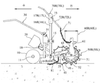
도 1은 본 발명의 파종장치의 측면도이다.
도 2는 본 발명의 파종장치의 정면도이다.
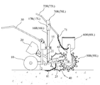
도 3은 파종작업을 할 때, 파종통을 지면으로 하강시킨 상태의 측면도이고,
도 4는 파종작업을 하지 않을 때, 파종통을 지면에서 상승시킨 상태의 측면도이고,
도 5는 파종작업을 하지 않을 때, 파종통을 지면에서 상승시킨 상태의 정면도이다. 1 is a side view of a seeding apparatus of the present invention.
2 is a front view of the seeding apparatus of the present invention.
3 is a side view of a state in which the seeding barrel is lowered to the ground when sowing work,
4 is a side view of a state in which the seeding barrel is raised from the ground when not sowing,
5 is a front view of a state in which the seeding barrel is raised from the ground when the seeding operation is not performed.
이하, 본 발명에 따른 바람직한 실시예를 첨부도면에 따라 상세히 설명한다. Hereinafter, preferred embodiments according to the present invention will be described in detail according to the accompanying drawings.
도 1은 본 발명의 파종장치의 측면도이고, 도 2는 본 발명의 파종장치의 정면도이다. 본 발명의 소형 동력 파종장치는, 도 1 및 도 2에 도시된 바와 같이, 하나의 축(11)상에 설치된 2개의 피동 바퀴(10); 상기 피동 바퀴(10)의 축(11)에 지지된 후방 가로 지지바(12) 및 상기 후방 가로 지지바(12)에서 수직으로 연장된 후방 세로 지지바(13)로 이루어진 후방 프레임;을 포함한다.1 is a side view of the seeding apparatus of the present invention, and FIG. 2 is a front view of the seeding apparatus of the present invention. Small power planting apparatus of the present invention, as shown in Figures 1 and 2, two driven wheels (10) installed on one shaft (11); And a rear frame composed of a rear
또한, 본 발명의 소형 동력 파종장치는, 상기 후방 세로 지지바(13)에 브라켓(15)으로 지지된 전방 좌측 세로바(16L)와, 상기 전방 좌측 세로바(16L)의 상단에 횡방향으로 연결된 전방 좌측 가로바(17L)와, 상기 후방 세로 지지바(13)에 브라켓(15)으로 지지된 전방 우측 세로바(16R)와, 상기 전방 우측 세로바(16R)의 상단에 횡방향으로 연결된 전방 우측 가로바(17R)로 이루어진 전방 프레임;을 포함한다. In addition, the small power planting apparatus of the present invention, the front left vertical bar (16L) supported by the
본 발명의 소형 동력 파종장치는, 상기 후방 세로 지지바(13)상에 브라켓(18)으로 지지된 소형 엔진(20)과, 상기 소형 엔진(20)에 구동축(21)으로 연결된 동력전달기구(25)와, 중심축상에 상기 동력전달기구(25)를 연결하여 상기 소형 엔진(20)의 구동력에 의해 회전하면서 지면을 구름이동하고, 원주면에는 일정한 간격을 두고 배치된 복수의 슬립방지용 날(41)이 구비된 구동 바퀴(40);를 포함한다.The small power seeding device of the present invention includes a
그리고, 상기 전방 좌측 세로바(16L)의 하단에는 좌측 지지축(64L)이 횡방향으로 연장되게 구비되고, 상기 전방 우측 세로바(16R)의 하단에는 우측 지지축(64R)이 횡방향으로 연장되게 구비된다. Further, a
또, 본 발명의 소형 동력 파종장치는, 상기 좌측 지지축(64L)상에 지지 암(63)으로 지지된 적어도 하나의 좌측 파종통(50L)과, 상기 좌측 파종통(50L)으로 종자를 공급하는 좌측 종자통(60L)과, 상기 우측 지지축(64R) 상에 지지암(63)으로 지지된 적어도 하나의 우측 파종통(50R)과, 상기 우측 파종통(50R)으로 종자를 공급하는 우측 종자통(60R)을 포함한다.In addition, the small power planting apparatus of the present invention supplies at least one left seeding tube (50L) supported by a support arm (63) on the left support shaft (64L) and seeds to the left seeding tube (50L). The left seed tube (60L), at least one right seeding tube (50R) supported by a support arm (63) on the right support shaft (64R), and the right supplying seeds to the right seeding tube (50R) It includes a seed container (60R).
설명하지 않은 도면부호 51은 파종통(50L,50R)에 지지브라켓(61)을 고정하는 보울트를 나타낸다.
상기 좌우측 파종통(50L,50R)은 도 1에 도시된 바와 같이, 복수개의 파종구(52)가 원주방향으로 일정한 간격을 두고 배치된다. 이들 파종구(52)는 좌,우측 파종통(50L,50R)이 지면을 구름이동하면서 지면에 가장 근접한 위치에 있을 때 개방되어 내부에 수용한 종자를 지면에 파종한다. The left and
그리고 본 발명의 소형 동력 파종장치는, 상기 후방 세로 지지바(13)의 상단에 틸팅 가능하게 연결된 핸들(30); 상기 전방 좌,우측 가로바(17L,17R) 상에 각각 고정핀(73)을 중심으로 피봇회전가능하게 연결된 좌,우측 파종통 승강 레버(72L,72R)와, 상기 좌,우측 파종통 승강 레버(72L,72R)를 각각 상승 위치와 하강 위치에 선택적으로 고정하는 좌, 우측 레버 고정판(70L,70R), 상기 좌,우측 파종통 승강 레버(72L,72R)의 하단과 상기 좌,우측 파종통(60L,60R)을 각각 연결하여 상기 좌,우측 파종통 승강 레버(72L,72R)의 상승 위치 또는 하강 위치에 대응하여 상기 좌,우측 파종통(50L,50R)을 상승 위치 또는 하강 위치로 승강시키는 승강 체인(71);을 포함한다. And the small power planting apparatus of the present invention, the
한편, 상기 파종통의 후방에는 파종한 지면을 흙으로 덮어주는 복토 체인(81)이 구비된다. On the other hand, the rear of the seeding tube is provided with a
10: 피동 바퀴 11: 축
12: 후방 가로 지지바 13: 후방 세로 지지바
15: 브라켓
16L: 전방 좌측 세로바 16R: 전방 우측 세로바
17L: 전방 좌측 가로바 17R: 전방 우측 가로바
18: 브라켓 20: 소형 엔진
21: 구동축 25: 동력전달기구
30: 핸들 40: 구동 바퀴
41: 슬립방지용 날
50L: 좌측 파종통 50R: 우측 파종통
52: 파종구 60L: 좌측 종자통
60R: 우측 종자통 61: 지지 브라켓
63: 지지 암 64L: 좌측 지지축
64R: 우측 지지축
70L: 좌측 레버 고정판 70R: 우측 레버 고정판
71: 승강 체인
72L: 좌측 파종통 승강 레버 72R: 우측 파종통 승강 레버
73: 고정핀 81: 복토 체인10: driven wheel 11: shaft
12: rear horizontal support bar 13: rear vertical support bar
15: bracket
16L: front left
17L: Front left
18: Bracket 20: Small engine
21: drive shaft 25: power transmission mechanism
30: handle 40: driving wheel
41: slip prevention blade
50L:
52: Seeding opening 60L: left seed container
60R: Right seed tube 61: Support bracket
63:
64R: Right support shaft
70L: Left
71: lifting chain
72L: left seeding
73: retaining pin 81: cover chain
Claims (4)
하나의 축(11)상에 설치된 2개의 피동 바퀴(10);
상기 피동 바퀴(10)의 축(11)에 지지된 후방 가로 지지바(12)와, 상기 후방 가로 지지바(12)에서 수직으로 연장된 후방 세로 지지바(13)로 이루어진 후방 프레임;
상기 후방 세로 지지바(13)에 브라켓(15)으로 지지된 전방 좌측 세로바(16L)와, 상기 전방 좌측 세로바(16L)의 상단에 횡방향으로 연결된 전방 좌측 가로바(17L)와, 상기 후방 세로 지지바(13)에 브라켓(15)으로 지지된 전방 우측 세로바(16R)와, 상기 전방 우측 세로바(16R)의 상단에 횡방향으로 연결된 전방 우측 가로바(17R)로 이루어진 전방 프레임;
상기 후방 세로 지지바(13)상에 브라켓(18)으로 지지된 소형 엔진(20); 상기 소형 엔진(20)에 구동축(21)으로 연결된 동력전달기구(25); 중심축상에 상기 동력전달기구(25)를 연결하여 상기 소형 엔진(20)의 구동력에 의해 회전하면서 지면을 구름이동하고, 원주면에는 일정한 간격을 두고 배치된 복수의 슬립방지용 날(41)이 구비된 구동 바퀴(40);
상기 전방 좌측 세로바(16L)의 하단에 각각 횡방향으로 연장되게 구비된 좌측 지지축(64L)상에 지지 암(63)으로 지지된 적어도 하나의 좌측 파종통(50L);
상기 좌측 파종통(50L)으로 종자를 공급하는 좌측 종자통(60L)과, 상기 우측 지지축(64R) 상에 지지암(63)으로 지지된 적어도 하나의 우측 파종통(50R)과, 상기 우측 파종통(50R)으로 종자를 공급하는 우측 종자통(60R); 및
상기 후방 세로 지지바(13)의 상단에 틸팅 가능하게 연결된 핸들(30);을 포함하는 것을 특징으로 하는 소형 동력 파종기.In the small power planting device,
Two driven wheels 10 installed on one shaft 11;
A rear frame composed of a rear horizontal support bar 12 supported by the shaft 11 of the driven wheel 10 and a rear vertical support bar 13 extending vertically from the rear horizontal support bar 12;
The front left vertical bar (16L) supported by the bracket 15 to the rear vertical support bar (13), and the front left horizontal bar (17L) transversely connected to the top of the front left vertical bar (16L), and A front frame consisting of a front right vertical bar 16R supported by a bracket 15 on a rear vertical support bar 13, and a front right horizontal bar 17R connected transversely to the top of the front right vertical bar 16R. ;
A small engine 20 supported by a bracket 18 on the rear vertical support bar 13; A power transmission mechanism 25 connected to the small engine 20 by a drive shaft 21; The power transmission mechanism 25 is connected to the central axis to rotate the cloud while rotating by the driving force of the small engine 20, and a plurality of slip-preventing blades 41 arranged at regular intervals on the circumferential surface are provided. Drive wheels 40;
At least one left seeding tube (50L) supported by a support arm (63) on the left support shaft (64L) provided to extend in the lateral direction at the bottom of the front left vertical bar (16L);
A left seed tube (60L) for supplying seeds to the left seeding tube (50L), at least one right seeding tube (50R) supported by a support arm (63) on the right support shaft (64R), and the right Right seed tube (60R) for supplying seeds to the seeding tube (50R); And
A small power planter comprising a; a handle (30) tiltably connected to the upper end of the rear vertical support bar (13).
상기 전방 좌,우측 가로바(17L,17R) 상에 각각 구비된 고정핀(73)을 중심으로 피봇회전가능하게 연결된 좌,우측 파종통 승강 레버(72L,72R)와, 상기 좌, 우측 파종통 승강 레버(72L,72R)를 상승 위치와 하강 위치에 선택적으로 고정하는 레버 고정판(70L,70R), 상기 좌,우측 파종통 승강 레버(72L,72R)의 하단과 상기 좌,우측 파종통(60L,60R)을 연결하여 상기 좌,우측 파종통 승강 레버(72L,72R)의 상승 위치 또는 하강 위치에 대응하여 상기 좌,우측 파종통(50L,50R)을 상승 위치 또는 하강 위치로 승강시키는 승강 체인(71);을 더 포함하는 것을 특징으로 하는 소형 동력 파종장치. According to claim 1,
The left and right seeding barrel lifting levers 72L and 72R pivotably connected to the fixing pins 73 provided on the front left and right horizontal bars 17L and 17R, respectively, and the left and right seeding barrels Lever fixing plates (70L, 70R) for selectively fixing the lifting levers (72L, 72R) to the raised and lowered positions, the lower left and right seeding barrels and the left and right seeding barrels (60L) of the lifting levers (72L, 72R) ,60R) to connect the left and right seeding barrel lifting levers 72L, 72R to the rising or falling positions, and the lifting chain for lifting the left and right seeding barrels 50L, 50R to the rising or falling positions (71); Small power planting device further comprising.
상기 좌,우측 파종통(50L,50R)은 각각 좌,우측 지지축(64L,64R)에 슬라이드 이동가능하게 설치된 것을 특징으로 하는 소형 동력 파종장치. According to claim 1,
The left and right planting barrels (50L, 50R) are small power planting devices characterized in that the slide is installed on the left and right support shafts (64L, 64R), respectively.
Priority Applications (1)
| Application Number | Priority Date | Filing Date | Title |
|---|---|---|---|
| KR1020180164492A KR102242009B1 (en) | 2018-12-18 | 2018-12-18 | Small-sized power seeding machine |
Applications Claiming Priority (1)
| Application Number | Priority Date | Filing Date | Title |
|---|---|---|---|
| KR1020180164492A KR102242009B1 (en) | 2018-12-18 | 2018-12-18 | Small-sized power seeding machine |
Publications (2)
| Publication Number | Publication Date |
|---|---|
| KR20200076005A true KR20200076005A (en) | 2020-06-29 |
| KR102242009B1 KR102242009B1 (en) | 2021-04-23 |
Family
ID=71400746
Family Applications (1)
| Application Number | Title | Priority Date | Filing Date |
|---|---|---|---|
| KR1020180164492A Active KR102242009B1 (en) | 2018-12-18 | 2018-12-18 | Small-sized power seeding machine |
Country Status (1)
| Country | Link |
|---|---|
| KR (1) | KR102242009B1 (en) |
Cited By (2)
| Publication number | Priority date | Publication date | Assignee | Title |
|---|---|---|---|---|
| CN112516498A (en) * | 2020-12-11 | 2021-03-19 | 曹太航 | Fire extinguishing vehicle |
| KR102424114B1 (en) * | 2021-11-23 | 2022-07-27 | 대한민국 | Robot of unmanned unicycle electric wheel type for upland crop management |
Citations (3)
| Publication number | Priority date | Publication date | Assignee | Title |
|---|---|---|---|---|
| KR200275285Y1 (en) * | 2002-02-06 | 2002-05-11 | 최선화 | Earth-moving and sowing equipment |
| KR100352292B1 (en) | 2000-03-30 | 2002-09-12 | 문동길 | spot auto seeder |
| KR101026319B1 (en) | 2010-04-19 | 2011-03-31 | 문동길 | Water- overflow-blocking device of a flooded spot seeding apparatus mounted on a riding-type paddy field work machine |
-
2018
- 2018-12-18 KR KR1020180164492A patent/KR102242009B1/en active Active
Patent Citations (3)
| Publication number | Priority date | Publication date | Assignee | Title |
|---|---|---|---|---|
| KR100352292B1 (en) | 2000-03-30 | 2002-09-12 | 문동길 | spot auto seeder |
| KR200275285Y1 (en) * | 2002-02-06 | 2002-05-11 | 최선화 | Earth-moving and sowing equipment |
| KR101026319B1 (en) | 2010-04-19 | 2011-03-31 | 문동길 | Water- overflow-blocking device of a flooded spot seeding apparatus mounted on a riding-type paddy field work machine |
Cited By (2)
| Publication number | Priority date | Publication date | Assignee | Title |
|---|---|---|---|---|
| CN112516498A (en) * | 2020-12-11 | 2021-03-19 | 曹太航 | Fire extinguishing vehicle |
| KR102424114B1 (en) * | 2021-11-23 | 2022-07-27 | 대한민국 | Robot of unmanned unicycle electric wheel type for upland crop management |
Also Published As
| Publication number | Publication date |
|---|---|
| KR102242009B1 (en) | 2021-04-23 |
Similar Documents
| Publication | Publication Date | Title |
|---|---|---|
| US4307674A (en) | Agricultural implement for planting seeds | |
| US8286566B2 (en) | Down pressure adjustment assembly for a disc opener of an agricultural implement | |
| CN105474846B (en) | A seedling-supporting seedling planting device for dry-land vegetable transplanting machine | |
| CN107873183B (en) | Double-roller supporting ditching, sowing and earthing device | |
| CN107690889B (en) | A kind of technology and device for co-sowing wide-width soil seeds | |
| CN108293376A (en) | A kind of hybrid power is from reseeding formula potato precision planter | |
| KR102242009B1 (en) | Small-sized power seeding machine | |
| CN109168356B (en) | Wheat narrow row line tillage seeder | |
| KR200219524Y1 (en) | A sowing machine for dogging a tractor | |
| CN112715076A (en) | Seeding device for vegetable planting and seeding method thereof | |
| US789516A (en) | Corn-planter. | |
| CN208783210U (en) | A kind of seeder convenient for adjusting line-spacing and spacing in the rows | |
| CN106717200A (en) | It is easy to reverse the seeder of earthing | |
| CN201315748Y (en) | Seeding machine | |
| KR20190121028A (en) | garlic seeding machine | |
| CN203735032U (en) | Peanut seeder capable of adjusting line spacing and seedling spacing | |
| CN209768187U (en) | Organic vegetable seeder | |
| KR20220125078A (en) | The sowing seed apparatus for garlic | |
| CN213404104U (en) | Seeding device convenient for seed sowing amount adjustment for agricultural planting | |
| CN209949839U (en) | Vegetable seed seeder | |
| CN2183655Y (en) | High-efficient multifunctional seeder | |
| CN215648093U (en) | Special ridging device for driving rake | |
| KR200352560Y1 (en) | A multipurpose seeder | |
| KR102767816B1 (en) | Sundae seedling mounting tray structure of the seedling planting device | |
| NO155951B (en) | DEVICE FOR PLANT APPLIANCES, PRESENTATION FOR FORESTRY PLANTING |
Legal Events
| Date | Code | Title | Description |
|---|---|---|---|
| A201 | Request for examination | ||
| PA0109 | Patent application |
St.27 status event code: A-0-1-A10-A12-nap-PA0109 |
|
| PA0201 | Request for examination |
St.27 status event code: A-1-2-D10-D11-exm-PA0201 |
|
| R17-X000 | Change to representative recorded |
St.27 status event code: A-3-3-R10-R17-oth-X000 |
|
| D13-X000 | Search requested |
St.27 status event code: A-1-2-D10-D13-srh-X000 |
|
| D14-X000 | Search report completed |
St.27 status event code: A-1-2-D10-D14-srh-X000 |
|
| PG1501 | Laying open of application |
St.27 status event code: A-1-1-Q10-Q12-nap-PG1501 |
|
| P22-X000 | Classification modified |
St.27 status event code: A-2-2-P10-P22-nap-X000 |
|
| E902 | Notification of reason for refusal | ||
| PE0902 | Notice of grounds for rejection |
St.27 status event code: A-1-2-D10-D21-exm-PE0902 |
|
| E13-X000 | Pre-grant limitation requested |
St.27 status event code: A-2-3-E10-E13-lim-X000 |
|
| P11-X000 | Amendment of application requested |
St.27 status event code: A-2-2-P10-P11-nap-X000 |
|
| P13-X000 | Application amended |
St.27 status event code: A-2-2-P10-P13-nap-X000 |
|
| E701 | Decision to grant or registration of patent right | ||
| PE0701 | Decision of registration |
St.27 status event code: A-1-2-D10-D22-exm-PE0701 |
|
| GRNT | Written decision to grant | ||
| PR0701 | Registration of establishment |
St.27 status event code: A-2-4-F10-F11-exm-PR0701 |
|
| PR1002 | Payment of registration fee |
St.27 status event code: A-2-2-U10-U11-oth-PR1002 Fee payment year number: 1 |
|
| PG1601 | Publication of registration |
St.27 status event code: A-4-4-Q10-Q13-nap-PG1601 |
|
| PR1001 | Payment of annual fee |
St.27 status event code: A-4-4-U10-U11-oth-PR1001 Fee payment year number: 4 |
|
| PR1001 | Payment of annual fee |
St.27 status event code: A-4-4-U10-U11-oth-PR1001 Fee payment year number: 5 |
|
| PR1001 | Payment of annual fee |
St.27 status event code: A-4-4-U10-U11-oth-PR1001 Fee payment year number: 6 |
|
| U11 | Full renewal or maintenance fee paid |
Free format text: ST27 STATUS EVENT CODE: A-4-4-U10-U11-OTH-PR1001 (AS PROVIDED BY THE NATIONAL OFFICE) Year of fee payment: 6 |