KR20200077435A - 에너지 소산 캡을 갖는 밀봉형 배터리 퓨즈 모듈 - Google Patents
에너지 소산 캡을 갖는 밀봉형 배터리 퓨즈 모듈 Download PDFInfo
- Publication number
- KR20200077435A KR20200077435A KR1020190168820A KR20190168820A KR20200077435A KR 20200077435 A KR20200077435 A KR 20200077435A KR 1020190168820 A KR1020190168820 A KR 1020190168820A KR 20190168820 A KR20190168820 A KR 20190168820A KR 20200077435 A KR20200077435 A KR 20200077435A
- Authority
- KR
- South Korea
- Prior art keywords
- fuse
- body portion
- mounting block
- fuse module
- hole
- Prior art date
- Legal status (The legal status is an assumption and is not a legal conclusion. Google has not performed a legal analysis and makes no representation as to the accuracy of the status listed.)
- Granted
Links
Images



Classifications
-
- H—ELECTRICITY
- H01—ELECTRIC ELEMENTS
- H01H—ELECTRIC SWITCHES; RELAYS; SELECTORS; EMERGENCY PROTECTIVE DEVICES
- H01H85/00—Protective devices in which the current flows through a part of fusible material and this current is interrupted by displacement of the fusible material when this current becomes excessive
- H01H85/0013—Means for preventing damage, e.g. by ambient influences to the fuse
-
- H—ELECTRICITY
- H01—ELECTRIC ELEMENTS
- H01M—PROCESSES OR MEANS, e.g. BATTERIES, FOR THE DIRECT CONVERSION OF CHEMICAL ENERGY INTO ELECTRICAL ENERGY
- H01M50/00—Constructional details or processes of manufacture of the non-active parts of electrochemical cells other than fuel cells, e.g. hybrid cells
- H01M50/50—Current conducting connections for cells or batteries
- H01M50/572—Means for preventing undesired use or discharge
- H01M50/574—Devices or arrangements for the interruption of current
- H01M50/581—Devices or arrangements for the interruption of current in response to temperature
-
- H01M2/348—
-
- H—ELECTRICITY
- H01—ELECTRIC ELEMENTS
- H01H—ELECTRIC SWITCHES; RELAYS; SELECTORS; EMERGENCY PROTECTIVE DEVICES
- H01H85/00—Protective devices in which the current flows through a part of fusible material and this current is interrupted by displacement of the fusible material when this current becomes excessive
- H01H85/0013—Means for preventing damage, e.g. by ambient influences to the fuse
- H01H85/0021—Means for preventing damage, e.g. by ambient influences to the fuse water or dustproof devices
- H01H85/003—Means for preventing damage, e.g. by ambient influences to the fuse water or dustproof devices casings for the fusible element
-
- H—ELECTRICITY
- H01—ELECTRIC ELEMENTS
- H01H—ELECTRIC SWITCHES; RELAYS; SELECTORS; EMERGENCY PROTECTIVE DEVICES
- H01H85/00—Protective devices in which the current flows through a part of fusible material and this current is interrupted by displacement of the fusible material when this current becomes excessive
- H01H85/02—Details
- H01H85/04—Fuses, i.e. expendable parts of the protective device, e.g. cartridges
- H01H85/05—Component parts thereof
- H01H85/143—Electrical contacts; Fastening fusible members to such contacts
-
- H—ELECTRICITY
- H01—ELECTRIC ELEMENTS
- H01H—ELECTRIC SWITCHES; RELAYS; SELECTORS; EMERGENCY PROTECTIVE DEVICES
- H01H85/00—Protective devices in which the current flows through a part of fusible material and this current is interrupted by displacement of the fusible material when this current becomes excessive
- H01H85/02—Details
- H01H85/04—Fuses, i.e. expendable parts of the protective device, e.g. cartridges
- H01H85/05—Component parts thereof
- H01H85/165—Casings
- H01H85/175—Casings characterised by the casing shape or form
-
- H—ELECTRICITY
- H01—ELECTRIC ELEMENTS
- H01H—ELECTRIC SWITCHES; RELAYS; SELECTORS; EMERGENCY PROTECTIVE DEVICES
- H01H85/00—Protective devices in which the current flows through a part of fusible material and this current is interrupted by displacement of the fusible material when this current becomes excessive
- H01H85/02—Details
- H01H85/20—Bases for supporting the fuse; Separate parts thereof
-
- H—ELECTRICITY
- H01—ELECTRIC ELEMENTS
- H01H—ELECTRIC SWITCHES; RELAYS; SELECTORS; EMERGENCY PROTECTIVE DEVICES
- H01H85/00—Protective devices in which the current flows through a part of fusible material and this current is interrupted by displacement of the fusible material when this current becomes excessive
- H01H85/02—Details
- H01H85/43—Means for exhausting or absorbing gases liberated by fusing arc, or for ventilating excess pressure generated by heating
-
- H—ELECTRICITY
- H01—ELECTRIC ELEMENTS
- H01M—PROCESSES OR MEANS, e.g. BATTERIES, FOR THE DIRECT CONVERSION OF CHEMICAL ENERGY INTO ELECTRICAL ENERGY
- H01M50/00—Constructional details or processes of manufacture of the non-active parts of electrochemical cells other than fuel cells, e.g. hybrid cells
- H01M50/50—Current conducting connections for cells or batteries
- H01M50/572—Means for preventing undesired use or discharge
-
- H—ELECTRICITY
- H02—GENERATION; CONVERSION OR DISTRIBUTION OF ELECTRIC POWER
- H02H—EMERGENCY PROTECTIVE CIRCUIT ARRANGEMENTS
- H02H7/00—Emergency protective circuit arrangements specially adapted for specific types of electric machines or apparatus or for sectionalised protection of cable or line systems, and effecting automatic switching in the event of an undesired change from normal working conditions
- H02H7/18—Emergency protective circuit arrangements specially adapted for specific types of electric machines or apparatus or for sectionalised protection of cable or line systems, and effecting automatic switching in the event of an undesired change from normal working conditions for batteries; for accumulators
-
- H—ELECTRICITY
- H01—ELECTRIC ELEMENTS
- H01H—ELECTRIC SWITCHES; RELAYS; SELECTORS; EMERGENCY PROTECTIVE DEVICES
- H01H85/00—Protective devices in which the current flows through a part of fusible material and this current is interrupted by displacement of the fusible material when this current becomes excessive
- H01H85/02—Details
- H01H85/0241—Structural association of a fuse and another component or apparatus
- H01H2085/025—Structural association with a binding post of a storage battery
-
- H—ELECTRICITY
- H01—ELECTRIC ELEMENTS
- H01H—ELECTRIC SWITCHES; RELAYS; SELECTORS; EMERGENCY PROTECTIVE DEVICES
- H01H85/00—Protective devices in which the current flows through a part of fusible material and this current is interrupted by displacement of the fusible material when this current becomes excessive
- H01H85/02—Details
- H01H85/38—Means for extinguishing or suppressing arc
- H01H2085/383—Means for extinguishing or suppressing arc with insulating stationary parts
-
- H—ELECTRICITY
- H01—ELECTRIC ELEMENTS
- H01H—ELECTRIC SWITCHES; RELAYS; SELECTORS; EMERGENCY PROTECTIVE DEVICES
- H01H85/00—Protective devices in which the current flows through a part of fusible material and this current is interrupted by displacement of the fusible material when this current becomes excessive
- H01H85/02—Details
- H01H85/04—Fuses, i.e. expendable parts of the protective device, e.g. cartridges
- H01H85/05—Component parts thereof
- H01H85/055—Fusible members
- H01H85/08—Fusible members characterised by the shape or form of the fusible member
- H01H85/10—Fusible members characterised by the shape or form of the fusible member with constriction for localised fusing
-
- H—ELECTRICITY
- H01—ELECTRIC ELEMENTS
- H01M—PROCESSES OR MEANS, e.g. BATTERIES, FOR THE DIRECT CONVERSION OF CHEMICAL ENERGY INTO ELECTRICAL ENERGY
- H01M2200/00—Safety devices for primary or secondary batteries
- H01M2200/10—Temperature sensitive devices
- H01M2200/103—Fuse
-
- H—ELECTRICITY
- H01—ELECTRIC ELEMENTS
- H01M—PROCESSES OR MEANS, e.g. BATTERIES, FOR THE DIRECT CONVERSION OF CHEMICAL ENERGY INTO ELECTRICAL ENERGY
- H01M2220/00—Batteries for particular applications
- H01M2220/20—Batteries in motive systems, e.g. vehicle, ship, plane
Landscapes
- Chemical & Material Sciences (AREA)
- Chemical Kinetics & Catalysis (AREA)
- Electrochemistry (AREA)
- General Chemical & Material Sciences (AREA)
- Fuses (AREA)
- Connection Of Batteries Or Terminals (AREA)
Abstract
Description
도 2는 도 1에 도시된 퓨즈 모듈의 구성요소들을 예시하는 분해도.
도 3은 도 1에 도시된 퓨즈 모듈의 구성요소들을 예시하는 절결도.
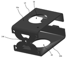
도 4는 도 1에 도시된 퓨즈 모듈의 퓨즈를 예시하는 사시도.
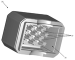
도 5는 도 1에 도시된 퓨즈 모듈의 하우징의 캡 부분을 예시하는 사시도.
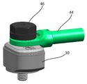
도 6a는 배터리 상에 설치된 도 1에 도시된 퓨즈 모듈을 예시하는 사시도.
도 6b는 배터리 상에 설치된 도 1에 도시된 퓨즈 모듈을 예시하는 단면도.
Claims (20)
- 퓨즈 모듈(fuse module)로서,
관통 연장되는 관통 구멍을 갖는 장착 블록;
퓨즈; 및
하우징
을 포함하고,
상기 퓨즈는,
상기 장착 블록의 상부 상에 배치되고, 상기 장착 블록의 상기 관통 구멍과 정렬되는 관통 구멍을 갖는 상부 부분;
상기 장착 블록의 저부 상에 배치되고, 상기 장착 블록의 상기 관통 구멍과 정렬되는 관통 구멍을 갖는 하부 부분; 및
상기 장착 블록의 측벽에 인접하게 배치되고, 상기 퓨즈의 상기 상부 부분을 상기 퓨즈의 상기 하부 부분에 연결하는 가용성 요소(fusible element)
를 포함하며,
상기 하우징은,
상기 장착 블록 및 상기 퓨즈를 감싸는 본체 부분으로서, 상기 본체 부분은 상기 장착 블록의 상기 관통 구멍과 정렬되고 상기 퓨즈의 상기 상부 및 하부 부분들의 아래에 놓인 표면들을 노출시키는 개구들을 상기 본체 부분의 상부 및 저부 표면들 내에서 갖는, 상기 본체 부분; 및
상기 본체 부분에 연결되고 상기 가용성 요소 위에 배치되는 캡(cap) 부분으로서, 상기 캡 부분은 상기 퓨즈에서의 과전류 상태의 발생 시에 에너지를 흡수하기 위해 상기 캡 부분의 내부 표면으로부터 연장되는 표면 특징부들을 갖는, 상기 캡 부분
을 포함하는, 퓨즈 모듈. - 제1항에 있어서, 상기 본체 부분은 상기 본체 부분의 상기 저부 표면으로부터 연장되는 환상 립(annular lip)을 포함하고, 상기 환상 립은 상기 본체 부분의 상기 저부 표면 내의 상기 개구를 둘러싸는, 퓨즈 모듈.
- 제1항에 있어서, 상기 본체 부분의 상기 상부 표면 내의 상기 개구 내에 배치되고 상기 퓨즈의 상기 상부 부분 상에 안착되는 전기 전도성 링(ring)을 추가로 포함하는, 퓨즈 모듈.
- 제3항에 있어서, 상기 전도성 링은 상기 본체 부분의 상기 상부 표면 내의 상기 개구로부터 돌출되고 상기 본체 부분의 상기 상부 표면 위로 연장되는, 퓨즈 모듈.
- 제1항에 있어서, 상기 캡 부분은 상기 본체 부분과 유체-밀봉 시일(fluid-tight seal)을 형성하는, 퓨즈 모듈.
- 제1항에 있어서, 상기 표면 특징부들은 리지(ridge)들, 돌출부들, 성곽부(castellation)들, 장벽(barrier)들, 채널들, 및 윤곽부(contour)들 중 하나 이상을 포함하는, 퓨즈 모듈.
- 제6항에 있어서, 상기 표면 특징부들은 리지들이 측벽들 상에 형성된 절두원추형 돌출부들을 포함하는, 퓨즈 모듈.
- 제1항에 있어서, 상기 장착 블록은 상기 캡 부분에 바로 인접하여 상기 가용성 요소 위에 배치되는 커버를 포함하는, 퓨즈 모듈.
- 제1항에 있어서, 상기 하우징은 전기 절연 탄성 재료로 형성되는, 퓨즈 모듈.
- 보호된 회로 설비(protected circuit arrangement)로서,
전도체의 링 단자와 배터리 사이에 전기적으로 직렬로 연결되는 퓨즈 모듈; 및
전기 절연 스크루(screw)
를 포함하고, 상기 퓨즈 모듈은,
관통 연장되는 관통 구멍을 갖는 장착 블록;
퓨즈; 및
하우징
을 포함하고,
상기 퓨즈는,
상기 장착 블록의 상부 상에 배치되고, 상기 장착 블록의 상기 관통 구멍과 정렬되는 관통 구멍을 갖는 상부 부분;
상기 장착 블록의 저부 상에 배치되고, 상기 장착 블록의 상기 관통 구멍과 정렬되는 관통 구멍을 갖는 하부 부분; 및
상기 장착 블록의 측벽에 인접하게 배치되고, 상기 퓨즈의 상기 상부 부분을 상기 퓨즈의 상기 하부 부분에 연결하는 가용성 요소
를 포함하며,
상기 하우징은,
상기 장착 블록 및 상기 퓨즈를 감싸는 본체 부분으로서, 상기 본체 부분은 상기 장착 블록의 상기 관통 구멍과 정렬되고 상기 퓨즈의 상기 상부 및 하부 부분들의 아래에 놓인 표면들을 노출시키는 개구들을 상기 본체 부분의 상부 및 저부 표면들 내에서 갖는, 상기 본체 부분; 및
상기 본체 부분에 연결되고 상기 가용성 요소 위에 배치되는 캡(cap) 부분으로서, 상기 캡 부분은 상기 퓨즈에서의 과전류 상태의 발생 시에 에너지를 흡수하기 위해 상기 캡 부분의 내부 표면으로부터 연장되는 표면 특징부들을 갖는, 상기 캡 부분
을 포함하고,
상기 전기 절연 스크루는 상기 링 단자 및 상기 퓨즈 모듈을 통해 연장되고 상기 배터리의 나삿니-형성된(threaded) 단자와 맞물림으로써, 상기 전기 절연 스크루는 상기 링 단자, 상기 퓨즈, 및 상기 배터리 단자를 서로 전기 연통하는 상태로 고정하는, 보호된 회로 설비. - 제10항에 있어서, 상기 본체 부분의 상기 상부 표면 내의 상기 개구 내에 배치되고 상기 퓨즈의 상기 상부 부분 상에 안착되는 전기 전도성 링을 추가로 포함하고, 상기 전도성 링은 상기 링 단자의 절연 코팅 내의 개구를 통해 연장되고 상기 링 단자의 전도성 부분과 맞물리는, 보호된 회로 설비.
- 제10항에 있어서, 상기 전기 절연 스크루의 금속 헤드와 상기 링 단자의 전도성 부분 사이에 배치되어 이들 사이에 전기 절연을 제공하는 전기 절연 링을 추가로 포함하는, 보호된 회로 설비.
- 제10항에 있어서, 상기 링 단자의 탄성 전기 절연성 코팅이 상기 본체 부분의 상기 상부 표면과 맞물리고 이와 함께 시일(seal)을 형성하는, 보호된 회로 설비.
- 제10항에 있어서, 상기 배터리 단자는 상기 본체 부분의 상기 저부 표면 내의 상기 개구를 통해 연장되고 상기 퓨즈의 상기 하부 부분과 맞물리는, 보호된 회로 설비.
- 제10항에 있어서, 상기 본체 부분은 상기 본체 부분의 상기 저부 표면으로부터 연장되는 환상 립을 포함하고, 상기 환상 립은 상기 본체 부분의 상기 저부 표면 내의 상기 개구를 둘러싸며, 상기 환상 립은 상기 배터리의 상부 표면과 맞물리고 이와 함께 시일을 형성하는, 보호된 회로 설비.
- 제10항에 있어서, 상기 캡 부분은 상기 본체 부분과 유체-밀봉 시일을 형성하는, 보호된 회로 설비.
- 제10항에 있어서, 상기 표면 특징부들은 리지들, 돌출부들, 성곽부들, 장벽들, 채널들, 및 윤곽부들 중 하나 이상을 포함하는, 보호된 회로 설비.
- 제17항에 있어서, 상기 표면 특징부들은 리지들이 측벽들 상에 형성된 절두원추형 돌출부들을 포함하는, 보호된 회로 설비.
- 제10항에 있어서, 상기 장착 블록은 상기 캡 부분에 바로 인접하여 상기 가용성 요소 위에 배치되는 커버를 포함하는, 보호된 회로 설비.
- 제10항에 있어서, 상기 하우징은 전기 절연 탄성 재료로 형성되는, 보호된 회로 설비.
Applications Claiming Priority (4)
| Application Number | Priority Date | Filing Date | Title |
|---|---|---|---|
| US201862782973P | 2018-12-20 | 2018-12-20 | |
| US62/782,973 | 2018-12-20 | ||
| US16/691,092 | 2019-11-21 | ||
| US16/691,092 US11417490B2 (en) | 2018-12-20 | 2019-11-21 | Sealed battery fuse module with energy dissipating cap |
Publications (2)
| Publication Number | Publication Date |
|---|---|
| KR20200077435A true KR20200077435A (ko) | 2020-06-30 |
| KR102871007B1 KR102871007B1 (ko) | 2025-10-16 |
Family
ID=68732969
Family Applications (1)
| Application Number | Title | Priority Date | Filing Date |
|---|---|---|---|
| KR1020190168820A Active KR102871007B1 (ko) | 2018-12-20 | 2019-12-17 | 에너지 소산 캡을 갖는 밀봉형 배터리 퓨즈 모듈 |
Country Status (4)
| Country | Link |
|---|---|
| US (1) | US11417490B2 (ko) |
| EP (1) | EP3671801B1 (ko) |
| KR (1) | KR102871007B1 (ko) |
| CN (1) | CN111354611B (ko) |
Families Citing this family (3)
| Publication number | Priority date | Publication date | Assignee | Title |
|---|---|---|---|---|
| US11195683B1 (en) * | 2021-02-11 | 2021-12-07 | Littelfuse, Inc. | Single bolt fuse assembly with an electrically isolated bolt |
| US11251009B1 (en) * | 2021-04-07 | 2022-02-15 | Littelfuse, Inc. | Fuse housing for safe outgassing |
| CN116013747A (zh) * | 2021-10-22 | 2023-04-25 | 苏州力特奥维斯保险丝有限公司 | 密封的直列式熔断器模块 |
Citations (4)
| Publication number | Priority date | Publication date | Assignee | Title |
|---|---|---|---|---|
| US20090066469A1 (en) * | 2007-09-10 | 2009-03-12 | Naeem Rahman | Battery fuse assembly |
| KR20140063675A (ko) * | 2011-09-12 | 2014-05-27 | 리텔퓨즈 인코포레이티드 | 퓨즈 조립체 |
| KR20170007320A (ko) * | 2014-05-02 | 2017-01-18 | 리텔퓨즈 인코포레이티드 | 리플로우 가능 회로 보호 장치 |
| KR20170095075A (ko) * | 2016-02-12 | 2017-08-22 | 주식회사 엘지화학 | 배터리 팩 및 이러한 배터리 팩을 포함하는 자동차 |
Family Cites Families (13)
| Publication number | Priority date | Publication date | Assignee | Title |
|---|---|---|---|---|
| US5645448A (en) * | 1995-10-16 | 1997-07-08 | Yazaki Corporation | Battery connecting module with fuse mounting |
| US6507265B1 (en) * | 1999-04-29 | 2003-01-14 | Cooper Technologies Company | Fuse with fuse link coating |
| US6902434B2 (en) * | 2002-07-23 | 2005-06-07 | Cooper Technologies Company | Battery fuse bus bar assembly |
| US7172462B1 (en) | 2005-08-15 | 2007-02-06 | Yazaki North America, Inc. | Fuse |
| CN101313382A (zh) * | 2005-10-03 | 2008-11-26 | 保险丝公司 | 具有空腔形成外壳的熔丝 |
| US7192319B1 (en) * | 2005-11-28 | 2007-03-20 | Cooper Technologies Company | Insulated cable termination assembly and method of fabrication |
| JP2010092730A (ja) * | 2008-10-08 | 2010-04-22 | Yazaki Corp | バッテリヒューズユニット用保護カバー及びその着脱方法 |
| US8669840B2 (en) * | 2010-05-18 | 2014-03-11 | Littelfuse, Inc. | Fuse assembly |
| JP6437239B2 (ja) * | 2013-08-28 | 2018-12-12 | デクセリアルズ株式会社 | ヒューズエレメント、ヒューズ素子 |
| US9660249B2 (en) * | 2013-10-01 | 2017-05-23 | Samsung Sdi Co., Ltd. | Rechargeable battery having a fuse |
| US9824840B2 (en) * | 2014-09-05 | 2017-11-21 | Littelfuse, Inc. | Mechanical disconnect switch with integrated fuse protection |
| WO2016127846A1 (zh) | 2015-02-14 | 2016-08-18 | 南京萨特科技发展有限公司 | 一种保护元件 |
| JP6433469B2 (ja) * | 2016-10-04 | 2018-12-05 | 矢崎総業株式会社 | バッテリ用接続ユニット及びバッテリ用接続ユニットの取付構造 |
-
2019
- 2019-11-21 US US16/691,092 patent/US11417490B2/en active Active
- 2019-11-29 EP EP19212596.1A patent/EP3671801B1/en active Active
- 2019-12-17 KR KR1020190168820A patent/KR102871007B1/ko active Active
- 2019-12-18 CN CN201911313436.5A patent/CN111354611B/zh active Active
Patent Citations (4)
| Publication number | Priority date | Publication date | Assignee | Title |
|---|---|---|---|---|
| US20090066469A1 (en) * | 2007-09-10 | 2009-03-12 | Naeem Rahman | Battery fuse assembly |
| KR20140063675A (ko) * | 2011-09-12 | 2014-05-27 | 리텔퓨즈 인코포레이티드 | 퓨즈 조립체 |
| KR20170007320A (ko) * | 2014-05-02 | 2017-01-18 | 리텔퓨즈 인코포레이티드 | 리플로우 가능 회로 보호 장치 |
| KR20170095075A (ko) * | 2016-02-12 | 2017-08-22 | 주식회사 엘지화학 | 배터리 팩 및 이러한 배터리 팩을 포함하는 자동차 |
Also Published As
| Publication number | Publication date |
|---|---|
| KR102871007B1 (ko) | 2025-10-16 |
| CN111354611B (zh) | 2025-01-28 |
| US20200203110A1 (en) | 2020-06-25 |
| EP3671801B1 (en) | 2025-01-08 |
| US11417490B2 (en) | 2022-08-16 |
| EP3671801A1 (en) | 2020-06-24 |
| CN111354611A (zh) | 2020-06-30 |
Similar Documents
| Publication | Publication Date | Title |
|---|---|---|
| US10930463B2 (en) | Ventilated fuse housing | |
| US20210233729A1 (en) | Electrical circuit breaker | |
| KR102871007B1 (ko) | 에너지 소산 캡을 갖는 밀봉형 배터리 퓨즈 모듈 | |
| CN106450063A (zh) | 二次电池 | |
| US11017972B2 (en) | Solderless surface mount fuse | |
| CN106450137A (zh) | 二次电池 | |
| US20210210300A1 (en) | Surface-mount type micro fuse | |
| EP3611751A1 (en) | Conductive connection structure, multifunctional high-voltage connector and battery product | |
| WO2018155161A1 (ja) | 温度ヒューズ及び電気接続箱 | |
| US2837614A (en) | Protectors for electric circuits | |
| US11469069B1 (en) | Airtight surface mount fuse with insert cavity | |
| CA3237692A1 (en) | Electrical panelboard for power distribution including a heatsink assembly | |
| KR20190095752A (ko) | 퓨징 버스바 | |
| CN115188645B (zh) | 熔断器及电子设备 | |
| KR20240166157A (ko) | 퓨즈 엘리먼트 | |
| EP4174900B1 (en) | Sealed inline fuse module | |
| KR20240072295A (ko) | 전기 퓨즈 | |
| JP2018181819A (ja) | サービスプラグ機能付き高電圧ヒューズ | |
| CN108711543B (zh) | 一种电动汽车熔断器 | |
| US11749483B1 (en) | Fuse with compartmentalized body and parallel fuse elements | |
| US4323873A (en) | Fuse | |
| KR101222840B1 (ko) | 파워아울렛 | |
| KR20190021107A (ko) | 세이프티 플러그 커넥터 | |
| KR20250143925A (ko) | 고전압 퓨즈 | |
| KR20240048047A (ko) | 고전압 퓨즈 |
Legal Events
| Date | Code | Title | Description |
|---|---|---|---|
| PA0109 | Patent application |
St.27 status event code: A-0-1-A10-A12-nap-PA0109 |
|
| PG1501 | Laying open of application |
St.27 status event code: A-1-1-Q10-Q12-nap-PG1501 |
|
| P22-X000 | Classification modified |
St.27 status event code: A-2-2-P10-P22-nap-X000 |
|
| P22-X000 | Classification modified |
St.27 status event code: A-2-2-P10-P22-nap-X000 |
|
| A201 | Request for examination | ||
| PA0201 | Request for examination |
St.27 status event code: A-1-2-D10-D11-exm-PA0201 |
|
| D13-X000 | Search requested |
St.27 status event code: A-1-2-D10-D13-srh-X000 |
|
| R18-X000 | Changes to party contact information recorded |
St.27 status event code: A-3-3-R10-R18-oth-X000 |
|
| E902 | Notification of reason for refusal | ||
| PE0902 | Notice of grounds for rejection |
St.27 status event code: A-1-2-D10-D21-exm-PE0902 |
|
| E13-X000 | Pre-grant limitation requested |
St.27 status event code: A-2-3-E10-E13-lim-X000 |
|
| P11-X000 | Amendment of application requested |
St.27 status event code: A-2-2-P10-P11-nap-X000 |
|
| D22 | Grant of ip right intended |
Free format text: ST27 STATUS EVENT CODE: A-1-2-D10-D22-EXM-PE0701 (AS PROVIDED BY THE NATIONAL OFFICE) |
|
| PE0701 | Decision of registration |
St.27 status event code: A-1-2-D10-D22-exm-PE0701 |
|
| PR1002 | Payment of registration fee |
St.27 status event code: A-2-2-U10-U11-oth-PR1002 Fee payment year number: 1 |
|
| U11 | Full renewal or maintenance fee paid |
Free format text: ST27 STATUS EVENT CODE: A-2-2-U10-U11-OTH-PR1002 (AS PROVIDED BY THE NATIONAL OFFICE) Year of fee payment: 1 |
|
| PG1601 | Publication of registration |
St.27 status event code: A-4-4-Q10-Q13-nap-PG1601 |
|
| Q13 | Ip right document published |
Free format text: ST27 STATUS EVENT CODE: A-4-4-Q10-Q13-NAP-PG1601 (AS PROVIDED BY THE NATIONAL OFFICE) |