KR20200079199A - 전기 플러그-인 연결체, 조립 연결체 및 회로 보드 구성체 - Google Patents
전기 플러그-인 연결체, 조립 연결체 및 회로 보드 구성체 Download PDFInfo
- Publication number
- KR20200079199A KR20200079199A KR1020190172185A KR20190172185A KR20200079199A KR 20200079199 A KR20200079199 A KR 20200079199A KR 1020190172185 A KR1020190172185 A KR 1020190172185A KR 20190172185 A KR20190172185 A KR 20190172185A KR 20200079199 A KR20200079199 A KR 20200079199A
- Authority
- KR
- South Korea
- Prior art keywords
- connector
- plug
- outer housing
- electrical
- counterpart
- Prior art date
- Legal status (The legal status is an assumption and is not a legal conclusion. Google has not performed a legal analysis and makes no representation as to the accuracy of the status listed.)
- Granted
Links
Images


Classifications
-
- H—ELECTRICITY
- H01—ELECTRIC ELEMENTS
- H01R—ELECTRICALLY-CONDUCTIVE CONNECTIONS; STRUCTURAL ASSOCIATIONS OF A PLURALITY OF MUTUALLY-INSULATED ELECTRICAL CONNECTING ELEMENTS; COUPLING DEVICES; CURRENT COLLECTORS
- H01R13/00—Details of coupling devices of the kinds covered by groups H01R12/70 or H01R24/00 - H01R33/00
- H01R13/46—Bases; Cases
- H01R13/502—Bases; Cases composed of different pieces
-
- H—ELECTRICITY
- H01—ELECTRIC ELEMENTS
- H01R—ELECTRICALLY-CONDUCTIVE CONNECTIONS; STRUCTURAL ASSOCIATIONS OF A PLURALITY OF MUTUALLY-INSULATED ELECTRICAL CONNECTING ELEMENTS; COUPLING DEVICES; CURRENT COLLECTORS
- H01R12/00—Structural associations of a plurality of mutually-insulated electrical connecting elements, specially adapted for printed circuits, e.g. printed circuit boards [PCB], flat or ribbon cables, or like generally planar structures, e.g. terminal strips, terminal blocks; Coupling devices specially adapted for printed circuits, flat or ribbon cables, or like generally planar structures; Terminals specially adapted for contact with, or insertion into, printed circuits, flat or ribbon cables, or like generally planar structures
- H01R12/70—Coupling devices
- H01R12/71—Coupling devices for rigid printing circuits or like structures
- H01R12/72—Coupling devices for rigid printing circuits or like structures coupling with the edge of the rigid printed circuits or like structures
- H01R12/73—Coupling devices for rigid printing circuits or like structures coupling with the edge of the rigid printed circuits or like structures connecting to other rigid printed circuits or like structures
-
- H—ELECTRICITY
- H01—ELECTRIC ELEMENTS
- H01R—ELECTRICALLY-CONDUCTIVE CONNECTIONS; STRUCTURAL ASSOCIATIONS OF A PLURALITY OF MUTUALLY-INSULATED ELECTRICAL CONNECTING ELEMENTS; COUPLING DEVICES; CURRENT COLLECTORS
- H01R24/00—Two-part coupling devices, or either of their cooperating parts, characterised by their overall structure
- H01R24/38—Two-part coupling devices, or either of their cooperating parts, characterised by their overall structure having concentrically or coaxially arranged contacts
- H01R24/40—Two-part coupling devices, or either of their cooperating parts, characterised by their overall structure having concentrically or coaxially arranged contacts specially adapted for high frequency
-
- H—ELECTRICITY
- H01—ELECTRIC ELEMENTS
- H01R—ELECTRICALLY-CONDUCTIVE CONNECTIONS; STRUCTURAL ASSOCIATIONS OF A PLURALITY OF MUTUALLY-INSULATED ELECTRICAL CONNECTING ELEMENTS; COUPLING DEVICES; CURRENT COLLECTORS
- H01R12/00—Structural associations of a plurality of mutually-insulated electrical connecting elements, specially adapted for printed circuits, e.g. printed circuit boards [PCB], flat or ribbon cables, or like generally planar structures, e.g. terminal strips, terminal blocks; Coupling devices specially adapted for printed circuits, flat or ribbon cables, or like generally planar structures; Terminals specially adapted for contact with, or insertion into, printed circuits, flat or ribbon cables, or like generally planar structures
- H01R12/70—Coupling devices
- H01R12/71—Coupling devices for rigid printing circuits or like structures
- H01R12/712—Coupling devices for rigid printing circuits or like structures co-operating with the surface of the printed circuit or with a coupling device exclusively provided on the surface of the printed circuit
- H01R12/716—Coupling device provided on the PCB
-
- H—ELECTRICITY
- H01—ELECTRIC ELEMENTS
- H01R—ELECTRICALLY-CONDUCTIVE CONNECTIONS; STRUCTURAL ASSOCIATIONS OF A PLURALITY OF MUTUALLY-INSULATED ELECTRICAL CONNECTING ELEMENTS; COUPLING DEVICES; CURRENT COLLECTORS
- H01R12/00—Structural associations of a plurality of mutually-insulated electrical connecting elements, specially adapted for printed circuits, e.g. printed circuit boards [PCB], flat or ribbon cables, or like generally planar structures, e.g. terminal strips, terminal blocks; Coupling devices specially adapted for printed circuits, flat or ribbon cables, or like generally planar structures; Terminals specially adapted for contact with, or insertion into, printed circuits, flat or ribbon cables, or like generally planar structures
- H01R12/70—Coupling devices
- H01R12/7082—Coupling device supported only by cooperation with PCB
-
- H—ELECTRICITY
- H01—ELECTRIC ELEMENTS
- H01R—ELECTRICALLY-CONDUCTIVE CONNECTIONS; STRUCTURAL ASSOCIATIONS OF A PLURALITY OF MUTUALLY-INSULATED ELECTRICAL CONNECTING ELEMENTS; COUPLING DEVICES; CURRENT COLLECTORS
- H01R12/00—Structural associations of a plurality of mutually-insulated electrical connecting elements, specially adapted for printed circuits, e.g. printed circuit boards [PCB], flat or ribbon cables, or like generally planar structures, e.g. terminal strips, terminal blocks; Coupling devices specially adapted for printed circuits, flat or ribbon cables, or like generally planar structures; Terminals specially adapted for contact with, or insertion into, printed circuits, flat or ribbon cables, or like generally planar structures
- H01R12/70—Coupling devices
- H01R12/71—Coupling devices for rigid printing circuits or like structures
- H01R12/75—Coupling devices for rigid printing circuits or like structures connecting to cables except for flat or ribbon cables
-
- H—ELECTRICITY
- H01—ELECTRIC ELEMENTS
- H01R—ELECTRICALLY-CONDUCTIVE CONNECTIONS; STRUCTURAL ASSOCIATIONS OF A PLURALITY OF MUTUALLY-INSULATED ELECTRICAL CONNECTING ELEMENTS; COUPLING DEVICES; CURRENT COLLECTORS
- H01R12/00—Structural associations of a plurality of mutually-insulated electrical connecting elements, specially adapted for printed circuits, e.g. printed circuit boards [PCB], flat or ribbon cables, or like generally planar structures, e.g. terminal strips, terminal blocks; Coupling devices specially adapted for printed circuits, flat or ribbon cables, or like generally planar structures; Terminals specially adapted for contact with, or insertion into, printed circuits, flat or ribbon cables, or like generally planar structures
- H01R12/70—Coupling devices
- H01R12/91—Coupling devices allowing relative movement between coupling parts, e.g. floating or self aligning
-
- H—ELECTRICITY
- H01—ELECTRIC ELEMENTS
- H01R—ELECTRICALLY-CONDUCTIVE CONNECTIONS; STRUCTURAL ASSOCIATIONS OF A PLURALITY OF MUTUALLY-INSULATED ELECTRICAL CONNECTING ELEMENTS; COUPLING DEVICES; CURRENT COLLECTORS
- H01R13/00—Details of coupling devices of the kinds covered by groups H01R12/70 or H01R24/00 - H01R33/00
- H01R13/02—Contact members
- H01R13/15—Pins, blades or sockets having separate spring member for producing or increasing contact pressure
- H01R13/17—Pins, blades or sockets having separate spring member for producing or increasing contact pressure with spring member on the pin
-
- H—ELECTRICITY
- H01—ELECTRIC ELEMENTS
- H01R—ELECTRICALLY-CONDUCTIVE CONNECTIONS; STRUCTURAL ASSOCIATIONS OF A PLURALITY OF MUTUALLY-INSULATED ELECTRICAL CONNECTING ELEMENTS; COUPLING DEVICES; CURRENT COLLECTORS
- H01R13/00—Details of coupling devices of the kinds covered by groups H01R12/70 or H01R24/00 - H01R33/00
- H01R13/02—Contact members
- H01R13/15—Pins, blades or sockets having separate spring member for producing or increasing contact pressure
- H01R13/187—Pins, blades or sockets having separate spring member for producing or increasing contact pressure with spring member in the socket
-
- H—ELECTRICITY
- H01—ELECTRIC ELEMENTS
- H01R—ELECTRICALLY-CONDUCTIVE CONNECTIONS; STRUCTURAL ASSOCIATIONS OF A PLURALITY OF MUTUALLY-INSULATED ELECTRICAL CONNECTING ELEMENTS; COUPLING DEVICES; CURRENT COLLECTORS
- H01R13/00—Details of coupling devices of the kinds covered by groups H01R12/70 or H01R24/00 - H01R33/00
- H01R13/62—Means for facilitating engagement or disengagement of coupling parts or for holding them in engagement
- H01R13/627—Snap or like fastening
-
- H—ELECTRICITY
- H01—ELECTRIC ELEMENTS
- H01R—ELECTRICALLY-CONDUCTIVE CONNECTIONS; STRUCTURAL ASSOCIATIONS OF A PLURALITY OF MUTUALLY-INSULATED ELECTRICAL CONNECTING ELEMENTS; COUPLING DEVICES; CURRENT COLLECTORS
- H01R13/00—Details of coupling devices of the kinds covered by groups H01R12/70 or H01R24/00 - H01R33/00
- H01R13/62—Means for facilitating engagement or disengagement of coupling parts or for holding them in engagement
- H01R13/629—Additional means for facilitating engagement or disengagement of coupling parts, e.g. aligning or guiding means, levers, gas pressure electrical locking indicators, manufacturing tolerances
-
- H—ELECTRICITY
- H01—ELECTRIC ELEMENTS
- H01R—ELECTRICALLY-CONDUCTIVE CONNECTIONS; STRUCTURAL ASSOCIATIONS OF A PLURALITY OF MUTUALLY-INSULATED ELECTRICAL CONNECTING ELEMENTS; COUPLING DEVICES; CURRENT COLLECTORS
- H01R13/00—Details of coupling devices of the kinds covered by groups H01R12/70 or H01R24/00 - H01R33/00
- H01R13/66—Structural association with built-in electrical component
-
- H—ELECTRICITY
- H01—ELECTRIC ELEMENTS
- H01R—ELECTRICALLY-CONDUCTIVE CONNECTIONS; STRUCTURAL ASSOCIATIONS OF A PLURALITY OF MUTUALLY-INSULATED ELECTRICAL CONNECTING ELEMENTS; COUPLING DEVICES; CURRENT COLLECTORS
- H01R24/00—Two-part coupling devices, or either of their cooperating parts, characterised by their overall structure
- H01R24/38—Two-part coupling devices, or either of their cooperating parts, characterised by their overall structure having concentrically or coaxially arranged contacts
- H01R24/40—Two-part coupling devices, or either of their cooperating parts, characterised by their overall structure having concentrically or coaxially arranged contacts specially adapted for high frequency
- H01R24/50—Two-part coupling devices, or either of their cooperating parts, characterised by their overall structure having concentrically or coaxially arranged contacts specially adapted for high frequency mounted on a PCB [Printed Circuit Board]
-
- H—ELECTRICITY
- H01—ELECTRIC ELEMENTS
- H01R—ELECTRICALLY-CONDUCTIVE CONNECTIONS; STRUCTURAL ASSOCIATIONS OF A PLURALITY OF MUTUALLY-INSULATED ELECTRICAL CONNECTING ELEMENTS; COUPLING DEVICES; CURRENT COLLECTORS
- H01R31/00—Coupling parts supported only by co-operation with counterpart
- H01R31/06—Intermediate parts for linking two coupling parts, e.g. adapter
-
- H—ELECTRICITY
- H01—ELECTRIC ELEMENTS
- H01R—ELECTRICALLY-CONDUCTIVE CONNECTIONS; STRUCTURAL ASSOCIATIONS OF A PLURALITY OF MUTUALLY-INSULATED ELECTRICAL CONNECTING ELEMENTS; COUPLING DEVICES; CURRENT COLLECTORS
- H01R2103/00—Two poles
Landscapes
- Details Of Connecting Devices For Male And Female Coupling (AREA)
- Coupling Device And Connection With Printed Circuit (AREA)
Abstract
Description
도면들 각각은 본 발명의 개별적인 특징들이 서로 조합되어 도시된 바람직한 예시적 실시예를 도시한다. 하나의 예시적인 실시예의 특징들은 동일한 예시적 실시예의 다른 특징들과 분리되게 구현될 수도 있고, 따라서 다른 예시적인 실시예들의 특징들을 가진 다른 유용한 조합 및 하위 조합을 형성하도록 당업자에 의하여 용이하게 조합될 수 있다.
동일한 기능의 요소들은 도면에서 동일한 참조 부호로 표시되어 있다.
도면에서, 각각의 경우에,
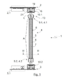
도 1 은 제 1 회로 보드 및 제 2 회로 보드를 포함하는 회로 보드 구성체와 상기 회로 보드들 사이에 배치된 연결 요소에 대한 단면도이다.
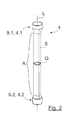
도 2 는 도 1 의 연결 요소의 외측 하우징의 사시도이다.
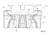
도 3 은 3 개의 스탬핑 조오에 의하여 변형되기 전에 도 1 에 도시된 단면 평면 III 을 따르는 도 1 의 연결 요소의 단면도를 도시한다.
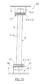
도 4 는 3 개의 스탬핑 조오에 의하여 변형된 후에 도 1 에 도시된 단면 평면 III 을 따른 도 1 의 연결 요소의 단면을 도시한다.
도 5 는 제 1 전기 플러그-인 커넥터 및 제 1 전기 카운터파트 플러그-인 커넥터를 가지는, 본 발명에 따른 전기 플러그-인 연결의 사시 단면도이다.
도 6 은 제 1 플러그-인 커넥터를 제 1 카운터파트 플러그-인 커넥터로 삽입하기 전 상태에서 도 5 의 발명에 따른 전기 플러그-인 연결의 단면도이다.
도 7 은 본 발명에 따라서 제 1 플러그-인 커넥터를 제 1 카운터플러그 플러그-인 커넥터로 삽입한 이후에 그리고 자체 중심 찾기 이전에 도 6 의 전기 플러그-인 연결을 도시한다.
도 8 은 본 발명에 따른 자체 중심 찾기 이후에 도 7 의 전기 플러그-인 연결을 도시한다.
도 9 는 접촉 스프링들의 사전 부하를 나타낼 목적으로 도 5 의 전기 플러그-인 연결의 접촉 영역의 확대된 단면도를 나타낸다.
도 10 은 높은 정도의 스프링 탄성을 가진 접촉 스프링들을 구비한 예시적인 실시예에 따른 전기 플러그 연결의 접촉 영역의 확대된 단면도이다.
도 11 은 제 1 플러그-인 커넥터를 제 1 카운터파트 플러그-인 커넥터에 삽입한 이후의 상태에서 종래 기술에 따른 조립 연결을 측면도로 도시한다.
도 12 는 제 1 플러그-인 커넥터를 제 1 카운터파트 플러그-인 커넥터로 삽입한 이후의 상태에서 본 발명에 따른 조립 연결을 측면도로 도시한다.
도 13 은 도 12 의 본 발명에 따른 조립 연결을 완전한 플러그-인 상태에서 도시한다.
도 14 는 제 1 접촉 영역 및 제 2 접촉 영역을 구비한 제 1 플러그-인 커넥터의 대안의 실시예를 도시한다.
5. 외측 하우징 9.1 제 1 플러그 인 커넥터
10.1 제 1 카운터파트 플러그-인 커넥터
14. 접촉 스프링 15. 제 1 접촉 영역
Claims (15)
- 제 1 전기 카운터파트 플러그-인 커넥터(10.1)를 포함하고 제 1 단부(4.1)에 배치된 제 1 전기 플러그-인 커넥터(9.1)를 가진 연결 요소(4)를 포함하는 전기 플러그-인 연결체(Electrical plug-in connection, 13)로서,
제 1 카운터파트 플러그-인 커넥터(10.1)는 접촉 스프링(14)들을 포함하고, 제 1 플러그-인 커넥터(9.1)는, 적어도 링 세그먼트 형상 원주 방식(ring-segment-shaped circumferential fashion)으로 연장된 제 1 접촉 영역(15)을 가진 전기 도전성 외측 하우징(5)을 포함하고, 접촉 스프링(14)들은 제 1 플러그-인 커넥터(9.1)와 제 1 카운터파트 플러그-인 커넥터(10.1) 사이에 전기적인 접촉 및 기계적인 연결을 형성하기 위하여 제 1 접촉 영역(15)을 통해 외측 하우징(5)상에 작용하고, 접촉 스프링(14)들은 제 1 접촉 영역(15)상에 작용함으로써 외측 하우징(5)에 축방향 힘(FA)이 작용하며, 상기 축방향 힘은 제 1 카운터파트 플러그-인 커넥터(10.1)의 길이 방향 축(LG)을 따라서 작용하고 외측 하우징(5)을 제 1 카운터파트 플러그-인 커넥터(10.1)의 축방향 단부 정지부(21)에 대하여 밀고, 그리고/또는 접촉 스프링(14)들은 외측 하우징(5)의 제 1 접촉 영역(15) 및 제 2 접촉 영역(23)상에 개별의 반경 방향 힘(FR)을 가하도록 설계되고, 상기 제 2 접촉 영역은 적어도 링 세그먼트 형상의 원주 방식(ring-segment-shaped circumferential fashion)으로 연장되고 연결 요소(4)의 길이 방향 축(L)을 따라서 제 1 접촉 영역(15)에 대하여 축방향으로 오프셋되고, 상기 반경 방향 힘은 제 1 카운터파트 플러그-인 커넥터(10.1)의 길이 방향 축에 대하여 직각으로 외측 하우징(5)상에 작용하는 것을 특징으로 하는, 전기 플러그-인 연결체(13). - 제 1 항에 있어서, 제 1 접촉 영역(15)의 외측 직경은 연결 요소(4)의 제 1 단부(4.1)의 방향으로 증가되는 것을 특징으로 하는, 전기 플러그-인 연결체(13).
- 제 1 항 또는 제 2 항에 있어서, 접촉 스프링(14)들은 제 2 접촉 영역(23)을 통하여 외측 하우징(5)상에 작용하도록 설계되는 것을 특징으로 하는, 전기 플러그-인 연결체(13).
- 제 1 항 내지 제 3 항중 어느 한 항에 있어서, 제 1 카운터파트 플러그-인 커넥터(10.1)는 제 1 플러그-인 커넥터(9.1)를 위한 깔때기 형상 삽입 영역(17)을 가진 카운터파트 플러그-인 커넥터 하우징(16)을 포함하는 것을 특징으로 하는, 전기 플러그-인 연결체(13).
- 제 1 항 내지 제 4 항중 어느 한 항에 있어서, 카운터파트 플러그-인 커넥터 하우징(16)은 칼러(collar, 18)를 포함하고, 상기 칼러는 제 1 카운터파트 플러그-인 커넥터(10.1)로 돌출되고, 접촉 스프링(14)들에 기계적으로 사전 부하(preload)를 가하기 위하여 접촉 스프링(14)들에 대한 맞닿음부(abutment)로서 설계되는 것을 특징으로 하는, 전기 플러그-인 연결체(13).
- 제 1 항 내지 제 5 항중 어느 한 항에 있어서, 제 1 플러그-인 커넥터(10.1)는 삽입 부분(19)을 포함하고, 상기 삽입 부분은, 제 1 플러그-인 커넥터(9.1)가 제 1 카운터파트 플러그-인 커넥터(10.1)와 함께 플러그 연결될 때, 제 1 플러그-인 커넥터(9,1)의 외측 하우징(5)에 적어도 부분적으로 진입하는 것을 특징으로 하는, 전기 플러그-인 연결체(13).
- 제 6 항에 있어서, 제 1 플러그-인 커넥터(9.1)와 제 1 카운터파트 플러그-인 커넥터(10.1)가 함께 플러그 연결된 상태에서, 제 1 접촉 영역(15)에 대향되게 위치된, 외측 하우징(5)의 내측 접촉 영역(15')에서 절연 부분(19)은 외측 하우징(5)과 접촉하는 것을 특징으로 하는, 전기 플러그-인 연결체(13).
- 제 6 항 또는 제 7 항에 있어서, 절연 부분(19)은 제 1 카운터파트 플러그-인 커넥터(10.1)내에서 외측 하우징(5)의 중심을 찾기 위하여 외측 하우징(5)의 방향으로 지향된 칼러(collar, 20)를 형성하는 것을 특징으로 하는, 전기 플러그-인 연결체(13).
- 제 6 항 내지 제 8 항중 어느 한 항에 있어서, 절연 부분(19)은 제 1 카운터파트 플러그-인 커넥터(10.1)에 제 1 플러그-인 커넥터(9.1)를 위한 축방향 단부 정지부(21)를 형성하는 것을 특징으로 하는, 전기 플러그-인 연결체(13).
- 제 1 항 내지 제 9 항중 어느 한 항에 따른 전기 플러그-인 연결체(13)를 위한 카운터파트 플러그-인 커넥터(10.1).
- 제 1 항 내지 제 9 항중 어느 한 항에 따른 전기 플러그-인 연결체(13)를 위한 연결 요소(4).
- 제 1 전기 조립체(2)를 제 2 전기 조립체(3)에 연결하기 위한 제 11 항에 따른 연결 요소(4)로서, 상기 연결 요소는 전기 도전성 재료로 만들어진 단단하고 튜브형인 외측 하우징(5) 및, 상기 외측 하우징(5)의 길이 방향 축(L)을 따라서 외측 하우징(5)의 내측에서 연장되는 전기 케이블(6)을 포함하고, 전기 케이블(6)은 적어도 하나의 내측 도전체(7) 및, 상기 적어도 하나의 내측 도전체(7)를 둘러싸는 유전체(8)를 포함하고, 외측 하우징(5)의 적어도 하나의 부분(A)은 전기 케이블(6)이 외측 하우징(5) 내부에 고정되는 방식으로 길이 방향 축(L)을 따라서 변형되는, 연결 요소(4).
- 제 1 전기 조립체(2) 및 제 2 전기 조립체(3)를 연결하기 위한 조립 연결체(22)로서, 상기 조립 연결체는, 제 1 전기 카운터파트 플러그-인 커넥터(10.1) 및 제 2 전기 카운터파트 플러그-인 커넥터(10.2)를 포함하고 제 1 단부(4.1)에 배치된 제 1 전기 플러그-인 커넥터(9.1) 및 제 2 단부(4.2)에 배치된 제 2 전기 플러그-인 커넥터(9.2)를 가진 연결 요소(4)를 포함하고, 카운터파트 플러그-인 커넥터(10.1, 10.2)들은 연결 요소(4)의 플러그-인 커넥터(9.1, 9.2)로의 연결을 위하여 그리고 각각의 경우에 하나의 전기 조립체(2,3)로의 연결을 위하여 설계되고, 제 1 카운터파트 플러그-인 커넥터(10.1)는 접촉 스프링(14)들을 포함하고, 제 1 플러그-인 커넥터(9.1)는 적어도 링 세그먼트 형상 원주 방식으로 연장되는 제 1 접촉 영역(15)을 가진 전기 도전성 외측 하우징(5)을 포함하고,
접촉 스프링(14)들은 제 1 플러그-인 커넥터(9.1)와 제 1 카운터파트 플러그-인 커넥터(10.1) 사이에 전기적인 접촉 및 기계적인 연결을 형성하기 위하여 제 1 접촉 영역(15)을 통하여 외측 하우징(5)상에 작용하고,
접촉 스프링(14)들은 제 1 접촉 영역(15)상에 작용함으로써 외측 하우징(5)에 축방향 힘(FA)이 작용하며, 상기 축방향 힘은 제 1 카운터파트 플러그-인 커넥터(10.1)의 길이 방향 축(LG)을 따라서 작용하고 외측 하우징(5)을 제 1 카운터파트 플러그-인 커넥터(10.1)의 축방향 단부 정지부(21)에 대하여 밀고,
그리고/또는 접촉 스프링(14)들은 외측 하우징(5)의 제 1 접촉 영역(15) 및 제 2 접촉 영역(23)상에 개별의 반경 방향 힘(FR)을 가하도록 설계되고, 상기 제 2 접촉 영역은 적어도 링 세그먼트 형상의 원주 방식(ring-segment-shaped circumferential fashion)으로 연장되고 연결 요소(4)의 길이 방향 축(L)을 따라서 제 1 접촉 영역(15)에 대하여 축방향으로 오프셋되고, 상기 반경 방향 힘은 제 1 카운터파트 플러그-인 커넥터(10.1)의 길이 방향 축에 대하여 직각으로 외측 하우징(5)상에 작용하는 것을 특징으로 하는, 조립 연결체(22). - 제 13 항에 있어서, 제 2 플러그-인 커넥터(9.2)는 제 1 플러그-인 커넥터(9.1)와 상이하게 설계되고, 바람직스럽게는 제 1 접촉 영역을 포함하며, 상기 제 1 접촉 영역은 적어도 링 세그먼트 형상 원주 방식으로 연장되고 연결 요소(4)의 길이 방향 축(L)을 다라서 실린더형으로 연장되는, 조립 연결체(22).
- 적어도 하나의 제 1 회로 보드(2) 및 하나의 제 2 회로 보드(3)를 포함하는 회로 보드 구성체(1)로서,
회로 보드(2,3)들은 상이한 평면들에서 서로 평행하게 연장되도록 배치되고, 회로 보드(2,3)들 사이에서 적어도 하나의 연결 요소(4)는 회로 보드(2,3)들을 서로 전기적으로 연결하도록 배치되고,
연결 요소(4)는 전기적으로 도전성인 외측 하우징(5)을 포함하고, 회로 보드(2,3)들중 적어도 하나는 접촉 스프링(14)들을 가진 제 1 전기 카운터파트 플러그-인 커넥터(10.1)를 포함하고,
접촉 스프링(14)들은, 제 1 플러그-인 커넥터(9.1)와 제 1 카운터파트 플러그-인 커넥터(10.1) 사이에 전기적인 접촉 및 기계적인 연결을 형성하기 위하여, 적어도 링 세그먼트 형상 원주 방식으로 연장되는, 제 1 전기 플러그-인 커넥터(9.1)의 제 1 접촉 영역(15)을 통하여 외측 하우징(5)상에 작용하고, 상기 제 1 전기 플러그-인 커넥터는 연결 요소(4)의 제 1 단부(4.1)에 배치되고,
접촉 스프링(14)들은 제 1 접촉 영역(15)상에 작용함으로써 외측 하우징(5)에 축방향 힘(FA)이 작용하며, 상기 축방향 힘은 제 1 카운터파트 플러그-인 커넥터(10.1)의 길이 방향 축(LG)을 따라서 작용하고 외측 하우징(5)을 제 1 카운터파트 플러그-인 커넥터(10.1)의 축방향 단부 정지부(21)에 대하여 밀고,
그리고/또는 접촉 스프링(14)들은 외측 하우징(5)의 제 1 접촉 영역(15) 및 제 2 접촉 영역(23)상에 개별의 반경 방향 힘(FR)을 가하도록 설계되고, 상기 제 2 접촉 영역은 적어도 링 세그먼트 형상의 원주 방식(ring-segment-shaped circumferential fashion)으로 연장되고 연결 요소(4)의 길이 방향 축(L)을 따라서 제 1 접촉 영역(15)에 대하여 축방향으로 오프셋되고, 상기 반경 방향 힘은 제 1 카운터파트 플러그-인 커넥터(10.1)의 길이 방향 축에 대하여 직각으로 외측 하우징(5)상에 작용하는 것을 특징으로 하는, 회로 보드 구성체(1).
Applications Claiming Priority (4)
| Application Number | Priority Date | Filing Date | Title |
|---|---|---|---|
| EP18215544.0A EP3627636B2 (de) | 2018-09-19 | 2018-12-21 | Elektrische steckverbindung, baugruppenverbindung und leiterplattenanordnung |
| EP18215544.0 | 2018-12-21 | ||
| EP19209296.3A EP3671978A1 (de) | 2018-12-21 | 2019-11-15 | Elektrische steckverbindung, baugruppenverbindung und leiterplattenanordnung |
| EP19209296.3 | 2019-11-15 |
Publications (2)
| Publication Number | Publication Date |
|---|---|
| KR20200079199A true KR20200079199A (ko) | 2020-07-02 |
| KR102883331B1 KR102883331B1 (ko) | 2025-11-06 |
Family
ID=71104758
Family Applications (1)
| Application Number | Title | Priority Date | Filing Date |
|---|---|---|---|
| KR1020190172185A Active KR102883331B1 (ko) | 2018-12-21 | 2019-12-20 | 전기 플러그-인 연결체, 조립 연결체 및 회로 보드 구성체 |
Country Status (3)
| Country | Link |
|---|---|
| US (1) | US11296465B2 (ko) |
| KR (1) | KR102883331B1 (ko) |
| CN (2) | CN111355077B (ko) |
Families Citing this family (5)
| Publication number | Priority date | Publication date | Assignee | Title |
|---|---|---|---|---|
| EP4133556B1 (en) * | 2020-09-09 | 2025-08-06 | Telefonaktiebolaget LM Ericsson (publ.) | A radio frequency connector and a communication module having the same |
| EP3989368A1 (de) * | 2020-10-20 | 2022-04-27 | Rosenberger Hochfrequenztechnik GmbH & Co. KG | Elektrischer steckverbinder, verbindungselement und leiterplattenanordnung |
| TWI756903B (zh) * | 2020-11-04 | 2022-03-01 | 緯穎科技服務股份有限公司 | 流體管路連接裝置、流體管路連接總成以及流體管路連接結構 |
| CN115224521B (zh) * | 2021-04-19 | 2024-12-03 | 上海莫仕连接器有限公司 | 浮动连接器及其组合 |
| JP7567668B2 (ja) * | 2021-06-04 | 2024-10-16 | 株式会社オートネットワーク技術研究所 | 接続装置 |
Citations (3)
| Publication number | Priority date | Publication date | Assignee | Title |
|---|---|---|---|---|
| US4377320A (en) * | 1980-11-26 | 1983-03-22 | Amp Incorporated | Coaxial connector |
| US20060099853A1 (en) * | 2004-11-05 | 2006-05-11 | Fred Sattele | Coaxial plug connector and mating connector |
| KR20180055834A (ko) * | 2015-10-07 | 2018-05-25 | 로젠버거 호흐프리쿠벤츠테흐닉 게엠베하 운트 코. 카게 | 플러그 및 소켓 커넥터 |
Family Cites Families (20)
| Publication number | Priority date | Publication date | Assignee | Title |
|---|---|---|---|---|
| US3871735A (en) * | 1973-08-23 | 1975-03-18 | Amp Inc | Shielded high voltage connector |
| US4426127A (en) * | 1981-11-23 | 1984-01-17 | Omni Spectra, Inc. | Coaxial connector assembly |
| US4963105A (en) | 1989-03-03 | 1990-10-16 | Dynawave Incorporated | Electrical connector assembly |
| ES2204511T3 (es) * | 1999-03-02 | 2004-05-01 | Huber+Suhner Ag | Conexion coaxial de placas de circuito impreso. |
| EP1094565A1 (de) | 1999-10-22 | 2001-04-25 | Huber+Suhner Ag | Koaxialer Steckverbinder |
| FR2808931B1 (fr) | 2000-05-10 | 2002-11-29 | Radiall Sa | Dispositif de raccordement d'un cable coaxial a une carte de circuit imprime |
| DK1641086T3 (da) | 2004-09-22 | 2007-03-26 | Rosenberger Hochfrequenztech | Koaksial-stik |
| US7097460B2 (en) * | 2005-02-01 | 2006-08-29 | Harris Corporation | Coaxial connector |
| JP2006260898A (ja) | 2005-03-16 | 2006-09-28 | Auto Network Gijutsu Kenkyusho:Kk | シールド導電路及びシート状導電路の製造方法 |
| DE102005034497A1 (de) | 2005-07-20 | 2007-02-01 | Ims Connector Systems Gmbh | Steckverbinder und Gegenstecker |
| US8087954B2 (en) | 2006-01-26 | 2012-01-03 | Huber+Suhner Ag | Coaxial plug-type connector arrangement |
| US8801459B2 (en) | 2010-01-25 | 2014-08-12 | Huber+Suhner Ag | Circuit board coaxial connector |
| JP5456504B2 (ja) * | 2010-02-10 | 2014-04-02 | ノーブル無線株式会社 | プッシュオン同軸コネクタ |
| CN201717406U (zh) * | 2010-04-16 | 2011-01-19 | 蔡闳宇 | 电源插座构造 |
| CN201699177U (zh) * | 2010-06-07 | 2011-01-05 | 深圳市电连精密技术有限公司 | 同轴连接器 |
| DE202012000487U1 (de) * | 2012-01-19 | 2012-02-27 | Rosenberger Hochfrequenztechnik Gmbh & Co. Kg | Verbindungselement |
| JP5872000B1 (ja) * | 2014-08-06 | 2016-03-01 | 日本航空電子工業株式会社 | 同軸コネクタ |
| KR102344819B1 (ko) * | 2016-05-12 | 2021-12-28 | 후버 앤드 주흐너 아게 | 회로 기판 동축 커넥터 |
| CN207743482U (zh) * | 2017-12-01 | 2018-08-17 | 深圳市百冠电池有限公司 | 一种电源插座 |
| CN208111727U (zh) * | 2018-04-16 | 2018-11-16 | 罗森伯格亚太电子有限公司 | 板间射频连接器 |
-
2019
- 2019-12-20 US US16/723,324 patent/US11296465B2/en active Active
- 2019-12-20 CN CN201911328605.2A patent/CN111355077B/zh active Active
- 2019-12-20 KR KR1020190172185A patent/KR102883331B1/ko active Active
- 2019-12-20 CN CN202111466458.2A patent/CN114300892B/zh active Active
Patent Citations (3)
| Publication number | Priority date | Publication date | Assignee | Title |
|---|---|---|---|---|
| US4377320A (en) * | 1980-11-26 | 1983-03-22 | Amp Incorporated | Coaxial connector |
| US20060099853A1 (en) * | 2004-11-05 | 2006-05-11 | Fred Sattele | Coaxial plug connector and mating connector |
| KR20180055834A (ko) * | 2015-10-07 | 2018-05-25 | 로젠버거 호흐프리쿠벤츠테흐닉 게엠베하 운트 코. 카게 | 플러그 및 소켓 커넥터 |
Also Published As
| Publication number | Publication date |
|---|---|
| US20200203901A1 (en) | 2020-06-25 |
| CN114300892B (zh) | 2024-06-21 |
| KR102883331B1 (ko) | 2025-11-06 |
| CN114300892A (zh) | 2022-04-08 |
| US11296465B2 (en) | 2022-04-05 |
| CN111355077A (zh) | 2020-06-30 |
| CN111355077B (zh) | 2021-12-28 |
Similar Documents
| Publication | Publication Date | Title |
|---|---|---|
| KR102883331B1 (ko) | 전기 플러그-인 연결체, 조립 연결체 및 회로 보드 구성체 | |
| US9735531B2 (en) | Float adapter for electrical connector and method for making the same | |
| KR102789811B1 (ko) | 전기 콘택 디바이스, 전기 연결 유닛 및 전기 케이블 조립하기 위한 방법 | |
| TWI608671B (zh) | 直接附接的連接器 | |
| CN110932003B (zh) | 连接元件、组件连接件、电路板装置和制造连接元件方法 | |
| US20130084741A1 (en) | Electromagnetic Shielding Device | |
| CN101836338B (zh) | 双曲面电接触件 | |
| EP2942844B1 (en) | Connector structure | |
| US7695322B2 (en) | Coaxial connector | |
| CN111919344B (zh) | 包括末端成叉形以接纳互补连接器的接触引脚的扁平中心接触件和配置成引导接触引脚的固体绝缘结构的rf连接器 | |
| CN112787121A (zh) | 同轴连接器及板对板连接器组件 | |
| US20200243991A1 (en) | Inner conductor element | |
| US11916340B2 (en) | Electrical plug connector, connecting element, and printed circuit board arrangement | |
| CN110783783B (zh) | 插接连接器和具有这种插接连接器的插接连接装置 | |
| EP3208894B1 (en) | Float adapter for electrical connector and method for making the same | |
| CN111213292A (zh) | 具有屏蔽元件的印刷电路板插接连接器 | |
| CN210866559U (zh) | 同轴连接器及板对板连接器组件 | |
| US12057661B2 (en) | Isolated pair quadrax interconnect | |
| WO2014053147A1 (en) | An electrical plug, an electrical jack, a jack and plug system and a method for producing an electrical plug | |
| CN117616637A (zh) | 接触套筒、连接装置、信号传输系统以及制作连接装置的方法 | |
| EP2779318A1 (en) | Method for assembling an electrical connector and electrical connector |
Legal Events
| Date | Code | Title | Description |
|---|---|---|---|
| PA0109 | Patent application |
St.27 status event code: A-0-1-A10-A12-nap-PA0109 |
|
| PG1501 | Laying open of application |
St.27 status event code: A-1-1-Q10-Q12-nap-PG1501 |
|
| A201 | Request for examination | ||
| PA0201 | Request for examination |
St.27 status event code: A-1-2-D10-D11-exm-PA0201 |
|
| E902 | Notification of reason for refusal | ||
| PE0902 | Notice of grounds for rejection |
St.27 status event code: A-1-2-D10-D21-exm-PE0902 |
|
| E13-X000 | Pre-grant limitation requested |
St.27 status event code: A-2-3-E10-E13-lim-X000 |
|
| P11-X000 | Amendment of application requested |
St.27 status event code: A-2-2-P10-P11-nap-X000 |
|
| P13-X000 | Application amended |
St.27 status event code: A-2-2-P10-P13-nap-X000 |
|
| D22 | Grant of ip right intended |
Free format text: ST27 STATUS EVENT CODE: A-1-2-D10-D22-EXM-PE0701 (AS PROVIDED BY THE NATIONAL OFFICE) |
|
| PE0701 | Decision of registration |
St.27 status event code: A-1-2-D10-D22-exm-PE0701 |
|
| F11 | Ip right granted following substantive examination |
Free format text: ST27 STATUS EVENT CODE: A-2-4-F10-F11-EXM-PR0701 (AS PROVIDED BY THE NATIONAL OFFICE) |
|
| PR0701 | Registration of establishment |
St.27 status event code: A-2-4-F10-F11-exm-PR0701 |
|
| PR1002 | Payment of registration fee |
St.27 status event code: A-2-2-U10-U11-oth-PR1002 Fee payment year number: 1 |
|
| U11 | Full renewal or maintenance fee paid |
Free format text: ST27 STATUS EVENT CODE: A-2-2-U10-U11-OTH-PR1002 (AS PROVIDED BY THE NATIONAL OFFICE) Year of fee payment: 1 |
|
| PG1601 | Publication of registration |
St.27 status event code: A-4-4-Q10-Q13-nap-PG1601 |
|
| Q13 | Ip right document published |
Free format text: ST27 STATUS EVENT CODE: A-4-4-Q10-Q13-NAP-PG1601 (AS PROVIDED BY THE NATIONAL OFFICE) |