KR20200083301A - Method for calibrating the alignment of moving object sensor - Google Patents
Method for calibrating the alignment of moving object sensor Download PDFInfo
- Publication number
- KR20200083301A KR20200083301A KR1020190175543A KR20190175543A KR20200083301A KR 20200083301 A KR20200083301 A KR 20200083301A KR 1020190175543 A KR1020190175543 A KR 1020190175543A KR 20190175543 A KR20190175543 A KR 20190175543A KR 20200083301 A KR20200083301 A KR 20200083301A
- Authority
- KR
- South Korea
- Prior art keywords
- sensor
- error
- alignment
- static
- object sensor
- Prior art date
- Legal status (The legal status is an assumption and is not a legal conclusion. Google has not performed a legal analysis and makes no representation as to the accuracy of the status listed.)
- Granted
Links
Images


Classifications
-
- G—PHYSICS
- G01—MEASURING; TESTING
- G01S—RADIO DIRECTION-FINDING; RADIO NAVIGATION; DETERMINING DISTANCE OR VELOCITY BY USE OF RADIO WAVES; LOCATING OR PRESENCE-DETECTING BY USE OF THE REFLECTION OR RERADIATION OF RADIO WAVES; ANALOGOUS ARRANGEMENTS USING OTHER WAVES
- G01S7/00—Details of systems according to groups G01S13/00, G01S15/00, G01S17/00
- G01S7/02—Details of systems according to groups G01S13/00, G01S15/00, G01S17/00 of systems according to group G01S13/00
- G01S7/40—Means for monitoring or calibrating
- G01S7/4004—Means for monitoring or calibrating of parts of a radar system
- G01S7/4026—Antenna boresight
-
- G—PHYSICS
- G01—MEASURING; TESTING
- G01S—RADIO DIRECTION-FINDING; RADIO NAVIGATION; DETERMINING DISTANCE OR VELOCITY BY USE OF RADIO WAVES; LOCATING OR PRESENCE-DETECTING BY USE OF THE REFLECTION OR RERADIATION OF RADIO WAVES; ANALOGOUS ARRANGEMENTS USING OTHER WAVES
- G01S7/00—Details of systems according to groups G01S13/00, G01S15/00, G01S17/00
- G01S7/48—Details of systems according to groups G01S13/00, G01S15/00, G01S17/00 of systems according to group G01S17/00
- G01S7/497—Means for monitoring or calibrating
- G01S7/4972—Alignment of sensor
-
- B—PERFORMING OPERATIONS; TRANSPORTING
- B60—VEHICLES IN GENERAL
- B60R—VEHICLES, VEHICLE FITTINGS, OR VEHICLE PARTS, NOT OTHERWISE PROVIDED FOR
- B60R21/00—Arrangements or fittings on vehicles for protecting or preventing injuries to occupants or pedestrians in case of accidents or other traffic risks
- B60R21/01—Electrical circuits for triggering passive safety arrangements, e.g. airbags, safety belt tighteners, in case of vehicle accidents or impending vehicle accidents
- B60R21/013—Electrical circuits for triggering passive safety arrangements, e.g. airbags, safety belt tighteners, in case of vehicle accidents or impending vehicle accidents including means for detecting collisions, impending collisions or roll-over
- B60R21/0134—Electrical circuits for triggering passive safety arrangements, e.g. airbags, safety belt tighteners, in case of vehicle accidents or impending vehicle accidents including means for detecting collisions, impending collisions or roll-over responsive to imminent contact with an obstacle, e.g. using radar systems
-
- B—PERFORMING OPERATIONS; TRANSPORTING
- B60—VEHICLES IN GENERAL
- B60W—CONJOINT CONTROL OF VEHICLE SUB-UNITS OF DIFFERENT TYPE OR DIFFERENT FUNCTION; CONTROL SYSTEMS SPECIALLY ADAPTED FOR HYBRID VEHICLES; ROAD VEHICLE DRIVE CONTROL SYSTEMS FOR PURPOSES NOT RELATED TO THE CONTROL OF A PARTICULAR SUB-UNIT
- B60W40/00—Estimation or calculation of non-directly measurable driving parameters for road vehicle drive control systems not related to the control of a particular sub unit, e.g. by using mathematical models
- B60W40/02—Estimation or calculation of non-directly measurable driving parameters for road vehicle drive control systems not related to the control of a particular sub unit, e.g. by using mathematical models related to ambient conditions
-
- B—PERFORMING OPERATIONS; TRANSPORTING
- B60—VEHICLES IN GENERAL
- B60W—CONJOINT CONTROL OF VEHICLE SUB-UNITS OF DIFFERENT TYPE OR DIFFERENT FUNCTION; CONTROL SYSTEMS SPECIALLY ADAPTED FOR HYBRID VEHICLES; ROAD VEHICLE DRIVE CONTROL SYSTEMS FOR PURPOSES NOT RELATED TO THE CONTROL OF A PARTICULAR SUB-UNIT
- B60W50/00—Details of control systems for road vehicle drive control not related to the control of a particular sub-unit, e.g. process diagnostic or vehicle driver interfaces
-
- G—PHYSICS
- G01—MEASURING; TESTING
- G01D—MEASURING NOT SPECIALLY ADAPTED FOR A SPECIFIC VARIABLE; ARRANGEMENTS FOR MEASURING TWO OR MORE VARIABLES NOT COVERED IN A SINGLE OTHER SUBCLASS; TARIFF METERING APPARATUS; MEASURING OR TESTING NOT OTHERWISE PROVIDED FOR
- G01D18/00—Testing or calibrating apparatus or arrangements provided for in groups G01D1/00 - G01D15/00
-
- G—PHYSICS
- G01—MEASURING; TESTING
- G01S—RADIO DIRECTION-FINDING; RADIO NAVIGATION; DETERMINING DISTANCE OR VELOCITY BY USE OF RADIO WAVES; LOCATING OR PRESENCE-DETECTING BY USE OF THE REFLECTION OR RERADIATION OF RADIO WAVES; ANALOGOUS ARRANGEMENTS USING OTHER WAVES
- G01S17/00—Systems using the reflection or reradiation of electromagnetic waves other than radio waves, e.g. lidar systems
- G01S17/88—Lidar systems specially adapted for specific applications
- G01S17/93—Lidar systems specially adapted for specific applications for anti-collision purposes
- G01S17/931—Lidar systems specially adapted for specific applications for anti-collision purposes of land vehicles
-
- G—PHYSICS
- G01—MEASURING; TESTING
- G01S—RADIO DIRECTION-FINDING; RADIO NAVIGATION; DETERMINING DISTANCE OR VELOCITY BY USE OF RADIO WAVES; LOCATING OR PRESENCE-DETECTING BY USE OF THE REFLECTION OR RERADIATION OF RADIO WAVES; ANALOGOUS ARRANGEMENTS USING OTHER WAVES
- G01S7/00—Details of systems according to groups G01S13/00, G01S15/00, G01S17/00
- G01S7/02—Details of systems according to groups G01S13/00, G01S15/00, G01S17/00 of systems according to group G01S13/00
- G01S7/40—Means for monitoring or calibrating
-
- G—PHYSICS
- G01—MEASURING; TESTING
- G01S—RADIO DIRECTION-FINDING; RADIO NAVIGATION; DETERMINING DISTANCE OR VELOCITY BY USE OF RADIO WAVES; LOCATING OR PRESENCE-DETECTING BY USE OF THE REFLECTION OR RERADIATION OF RADIO WAVES; ANALOGOUS ARRANGEMENTS USING OTHER WAVES
- G01S7/00—Details of systems according to groups G01S13/00, G01S15/00, G01S17/00
- G01S7/52—Details of systems according to groups G01S13/00, G01S15/00, G01S17/00 of systems according to group G01S15/00
- G01S7/52004—Means for monitoring or calibrating
-
- G—PHYSICS
- G06—COMPUTING OR CALCULATING; COUNTING
- G06T—IMAGE DATA PROCESSING OR GENERATION, IN GENERAL
- G06T7/00—Image analysis
- G06T7/80—Analysis of captured images to determine intrinsic or extrinsic camera parameters, i.e. camera calibration
-
- B—PERFORMING OPERATIONS; TRANSPORTING
- B60—VEHICLES IN GENERAL
- B60W—CONJOINT CONTROL OF VEHICLE SUB-UNITS OF DIFFERENT TYPE OR DIFFERENT FUNCTION; CONTROL SYSTEMS SPECIALLY ADAPTED FOR HYBRID VEHICLES; ROAD VEHICLE DRIVE CONTROL SYSTEMS FOR PURPOSES NOT RELATED TO THE CONTROL OF A PARTICULAR SUB-UNIT
- B60W50/00—Details of control systems for road vehicle drive control not related to the control of a particular sub-unit, e.g. process diagnostic or vehicle driver interfaces
- B60W2050/0062—Adapting control system settings
- B60W2050/0075—Automatic parameter input, automatic initialising or calibrating means
-
- B—PERFORMING OPERATIONS; TRANSPORTING
- B60—VEHICLES IN GENERAL
- B60W—CONJOINT CONTROL OF VEHICLE SUB-UNITS OF DIFFERENT TYPE OR DIFFERENT FUNCTION; CONTROL SYSTEMS SPECIALLY ADAPTED FOR HYBRID VEHICLES; ROAD VEHICLE DRIVE CONTROL SYSTEMS FOR PURPOSES NOT RELATED TO THE CONTROL OF A PARTICULAR SUB-UNIT
- B60W50/00—Details of control systems for road vehicle drive control not related to the control of a particular sub-unit, e.g. process diagnostic or vehicle driver interfaces
- B60W2050/0062—Adapting control system settings
- B60W2050/0075—Automatic parameter input, automatic initialising or calibrating means
- B60W2050/0083—Setting, resetting, calibration
-
- B60W2420/52—
-
- B—PERFORMING OPERATIONS; TRANSPORTING
- B60—VEHICLES IN GENERAL
- B60W—CONJOINT CONTROL OF VEHICLE SUB-UNITS OF DIFFERENT TYPE OR DIFFERENT FUNCTION; CONTROL SYSTEMS SPECIALLY ADAPTED FOR HYBRID VEHICLES; ROAD VEHICLE DRIVE CONTROL SYSTEMS FOR PURPOSES NOT RELATED TO THE CONTROL OF A PARTICULAR SUB-UNIT
- B60W2420/00—Indexing codes relating to the type of sensors based on the principle of their operation
- B60W2420/54—Audio sensitive means, e.g. ultrasound
-
- B60W2420/62—
-
- B—PERFORMING OPERATIONS; TRANSPORTING
- B60—VEHICLES IN GENERAL
- B60W—CONJOINT CONTROL OF VEHICLE SUB-UNITS OF DIFFERENT TYPE OR DIFFERENT FUNCTION; CONTROL SYSTEMS SPECIALLY ADAPTED FOR HYBRID VEHICLES; ROAD VEHICLE DRIVE CONTROL SYSTEMS FOR PURPOSES NOT RELATED TO THE CONTROL OF A PARTICULAR SUB-UNIT
- B60W2554/00—Input parameters relating to objects
Landscapes
- Engineering & Computer Science (AREA)
- Physics & Mathematics (AREA)
- General Physics & Mathematics (AREA)
- Remote Sensing (AREA)
- Radar, Positioning & Navigation (AREA)
- Computer Networks & Wireless Communication (AREA)
- Electromagnetism (AREA)
- Mechanical Engineering (AREA)
- Automation & Control Theory (AREA)
- Transportation (AREA)
- Human Computer Interaction (AREA)
- Radar Systems Or Details Thereof (AREA)
- Computer Vision & Pattern Recognition (AREA)
- Theoretical Computer Science (AREA)
- Mathematical Physics (AREA)
Abstract
이동하는 오브젝트 센서(object sensor)의 정렬을 교정(calibrating)하기 위한 방법은 오브젝트 센서의 이동을 기록하는 단계, 오브젝트 센서의 상이한 위치들에서 이동하는 오브젝트 센서에 의해 적어도 하나의 정적 오브젝트를 복수 회 검출하는 단계, 오브젝트 센서의 대응하는 위치에 대한 정적 오브젝트의 상대 위치를 계산하는 단계, 오브젝트 센서의 정렬 에러를 가정하여 상대 위치로부터 정적 오브젝트의 예상 위치를 계산하는 단계, 예상 위치로부터 에러 변수를 계산하는 단계, 오브젝트 센서의 정렬 에러를 조정함으로써 에러 변수를 최소화하는 단계를 포함한다.A method for calibrating the alignment of a moving object sensor includes recording the movement of the object sensor, detecting at least one static object multiple times by the moving object sensor at different positions of the object sensor Step, calculating the relative position of the static object with respect to the corresponding position of the object sensor, calculating the expected position of the static object from the relative position assuming the alignment error of the object sensor, and calculating the error variable from the expected position And minimizing the error variable by adjusting the alignment error of the object sensor.
Description
본 발명은 이동하는 오브젝트 센서(object sensor), 특히 차량 내의 이동되는 오브젝트 센서, 예를 들어 차량에 설치된 오브젝트 센서의 정렬을 교정(calibrating)하기 위한 방법에 관한 것이다.The present invention relates to a moving object sensor, in particular a method for calibrating the alignment of a moving object sensor in a vehicle, for example an object sensor installed in a vehicle.
현대 자동차, 특히 부분 자율 또는 자율로 주행하는 자동차에는, 차량 환경에 대한 차량의 자기 위치 측정을 위해 사용되는 다양한 센서가 설치되어 있다. 이를 위해, 차량의 주변에서 특수한 센서 시스템을 통해 두드러진 정적 구조 및 패턴, 소위 위치 피처(feature)가 기록되고, 이러한 위치 피처에 대한 차량의 위치 결정을 위해 사용된다. 일반적인 센서는 카메라, 레이더, 초음파 또는 레이저 스캐너 장치이다. 주행 중에, 센서 시스템에 의해 기록된 센서 데이터를 처리함으로써, 관심 있는 구조가 기록될 수 있고, 맵 내의 대응하는 엔트리에 할당되어, 차량 위치 및 차량의 정렬을 계산할 수 있다. 주행 중에 자동으로 실행되는 이러한 위치 결정의 품질은 본질적으로 위치 피처의 기록의 정확도 및 예를 들어 이전에 알려진 맵 오브젝트의 그 할당의 중요성에 의존한다. 측정의 정확도는 다시 각각의 사용된 센서 시스템 및 그 교정에 의존한다.Background Art In modern automobiles, in particular, autonomous or autonomous vehicles, various sensors are used to measure the vehicle's magnetic position relative to the vehicle environment. To this end, prominent static structures and patterns, so-called location features, are recorded through a special sensor system in the vicinity of the vehicle and are used to determine the vehicle's position relative to these location features. Typical sensors are cameras, radar, ultrasonic or laser scanner devices. While driving, by processing the sensor data recorded by the sensor system, structures of interest can be recorded and assigned to corresponding entries in the map to calculate the vehicle position and alignment of the vehicle. The quality of this positioning, which is performed automatically during driving, essentially depends on the accuracy of the recording of the location features and the importance of their allocation of previously known map objects, for example. The accuracy of the measurement again depends on each sensor system used and its calibration.
센서 시스템의 교정은 복잡하고, 시간이 걸리며, 이상적으로는 주행 중에도, 정기적으로 반복되어야 하는데, 왜냐하면 교정 프로세스를 통해 발생되는 파라미터는 예를 들어 시간이 지남에 따라 기계적 또는 열적 영향으로 인해 변경될 수 있는 센서 특성의 스냅 샷에만 항상 관련되기 때문이다.Calibration of the sensor system is complex, time consuming and, ideally, must be repeated regularly, even while driving, because the parameters generated through the calibration process can change over time, for example, due to mechanical or thermal effects. This is because it is always relevant only to snapshots of sensor characteristics.
교정 프로세스 동안 센서의 외부 및 고유 파라미터가 결정된다. 각 센서에 대한 고유 파라미터는 센서의 측정 절차의 특별한 특성 및 편차를 설명하지만, 외부 파라미터에 의해서는 본질적으로 차량 내의 센서의 구체적인 설치 위치 및 정렬, 예를 들어 차량 종축에 대한 센서의 정렬이 결정된다. 센서의 정렬과 관련하여, 정렬의 가장 작은 변화조차도 먼 범위의 측정에 큰 영향을 미쳐서, 이는 위치 결정을 크게 손상시킬 수 있다.During the calibration process external and unique parameters of the sensor are determined. The unique parameters for each sensor describe the specific characteristics and deviations of the sensor's measurement procedure, but external parameters essentially determine the specific installation position and alignment of the sensor in the vehicle, eg the alignment of the sensor to the vehicle longitudinal axis. . With regard to the alignment of the sensor, even the smallest change in alignment has a great influence on the measurement of a long range, which can greatly impair the positioning.
여기서 일 양태는 차량 축에 대한 센서의 실제 위치의 측 방향 편차를 나타낸다. 일반적으로, 차량 센서의 측 방향 위치는 설치 동안 이미 큰 정확도로 결정될 수 있으므로, 각각의 차량 모델의 치수에 따라, 차량 종축 또는 차량에 의해 사용되는 차선에 대한 센서 위치의 측 방향 편차의 신뢰성 있는 결정이 결정될 수 있다. 설치 위치의 측정 시의 만일의 에러 또는 후속적으로 차량에서 센서를 사용하는 동안 발생하는 측 방향 편차에 대한 에러는 차량 환경에서 검출된 오브젝트의 위치 에러로 일대일로 전달된다. 따라서 측 방향 편차로 인해 야기되는 위치 결정의 에러는 일반적으로 무시할 수 있을 정도로 작다.One aspect here represents the lateral deviation of the actual position of the sensor relative to the vehicle axis. In general, since the lateral position of the vehicle sensor can already be determined with great accuracy during installation, depending on the dimensions of each vehicle model, a reliable determination of the lateral deviation of the sensor position relative to the vehicle longitudinal axis or the lane used by the vehicle This can be determined. An error in case of measurement of an installation position or an error in a lateral deviation occurring while using a sensor in a vehicle is transmitted one-to-one as a position error of an object detected in the vehicle environment. Therefore, the positioning error caused by the lateral deviation is generally negligibly small.
각도 에러가 센서와 검출된 오브젝트 사이의 거리에 따라 위치 결정에 상이한 강도로 영향을 미치기 때문에, 훨씬 더 큰 문제는 공간에서의 센서의 배향이다. 예를 들어 1 도의 방위각 에러가 존재하는 경우, 60 미터 떨어진 측정 지점에서의 측 방향 에러는 이미 약 1 미터이다. 이 경우 센서가 오브젝트로부터 멀어질수록, 에러는 더 커진다. 센서를 영구 작동 상태로 설치할 때 가능한 한 최대한 주의를 기울여도 공간에서의 센서의 배향 편차가 종종 발생한다.A much larger problem is the orientation of the sensor in space, because the angular error affects the positioning with different intensity depending on the distance between the sensor and the detected object. For example, if there is an azimuth angle error of 1 degree, the lateral error at a measurement point 60 meters away is already about 1 meter. In this case, the farther the sensor is from the object, the greater the error. When installing the sensor in permanent operation, deviations in the orientation of the sensor in space often occur even with the utmost care possible.
예를 들어 센서를 이들의 정렬과 관련하여 교정하기 위한 방법은 종래 기술, 예를 들어 로봇 공학 분야로부터 알려져 있다. 적어도 종래 기술에서 설명된 해결 방안은 완전 자동으로 작동한다. 발견된 교정 파라미터의 후속 검증이 종종 필요하다. 교정 프로세스는 종종 시간이 많이 걸리고, 특별히 훈련된 인력이 필요한데, 왜냐하면 특히 교정 방법의 검증은 일반적으로 특별한 기술 지원을 통해서만 수행될 수 있기 때문이다.Methods for calibrating sensors in relation to their alignment, for example, are known from the prior art, for example robotics. At least the solutions described in the prior art work fully automatically. Subsequent verification of the calibration parameters found is often necessary. The calibration process is often time consuming and requires specially trained personnel, especially verification of calibration methods can generally only be performed with special technical support.
미국 특허 출원 US2010/0165102 A1에는, 예를 들어 이미지 처리에 의해 차량 카메라의 경사각을 결정하기 위한 방법이 설명되어 있으며, 여기서 정적 오브젝트는 차량에 설치된 이동하는 카메라의 복수의 이미지로 기록되고, 개별 이미지에서 정적 오브젝트의 위치를 변경함으로써 카메라 편차가 추론된다. 이 경우 차량은 전용 라인에서 이동하고 있다고 가정한다. 또한, 측정에 대한 차량 축의 정렬의 영향을 배제할 수 있기 위해 차량의 조향각이 기록된다.US patent application US2010/0165102 A1 describes a method for determining the tilt angle of a vehicle camera, for example by image processing, wherein a static object is recorded as a plurality of images of a moving camera installed in a vehicle, and individual images By changing the position of the static object in the camera deviation is inferred. In this case, it is assumed that the vehicle is moving on a dedicated line. In addition, the steering angle of the vehicle is recorded so that the influence of the alignment of the vehicle axis on the measurement can be excluded.
US2016/02267657 A1에는 차량 카메라의 동적 교정을 위한 방법이 설명되어 있고, 여기서 차량에 설치된 카메라가 직선 상으로 이동되고, 이미지에서 검출된 복수의 오브젝트로부터 오브젝트 궤적이 결정되고, 그로부터 다시 오브젝트 궤적의 소실점이 결정된다. 그런 다음 소실점의 위치 변경으로부터, 카메라의 가능한 오정렬이 결정될 수 있다.US2016/02267657 A1 describes a method for dynamic calibration of a vehicle camera, wherein the camera installed in the vehicle is moved in a straight line, the object trajectory is determined from a plurality of objects detected in the image, and again the vanishing point of the object trajectory This is decided. Then, from a change in the position of the vanishing point, a possible misalignment of the camera can be determined.
JP 2008 222 345 A에는 또한 카메라에 의해 검출된 복수의 정적 오브젝트의 위치들의 시간적 변화로부터 차량 이동으로 역 계산되는 카메라 기반 방법이 설명되어 있다.JP 2008 222 345 A also describes a camera-based method that is inversely calculated from the temporal changes in the positions of a plurality of static objects detected by the camera to the vehicle movement.
US 2013/0218398 A1에는 오브젝트 센서의 오정렬을 결정하기 위한 방법이 설명되어 있고, 여기서 선형 차량 이동 동안 하나 이상의 오브젝트가 기록되고, 차량이 이동할 때 오브젝트가 기록되는 각도의 시간적 프로파일이 차량 이동으로부터 예상되는 각도와 비교된다. 그런 다음 측정 값과 예상 값 사이의 편차로부터 센서의 만일의 오정렬이 추론된다.US 2013/0218398 A1 describes a method for determining misalignment of an object sensor, where one or more objects are recorded during linear vehicle movement, and a temporal profile of the angle at which objects are recorded when the vehicle is moving is expected from vehicle movement. Compared to the angle. Then, the sensor misalignment is inferred from the deviation between the measured value and the expected value.
유사한 방법이 US 2015/0276923 A1에 설명되어 있으며, 여기서 정적 오브젝트는 적어도 2 개의 상이한 시간에 기록되고, 차량 이동으로부터 예상되는 기록 각도와 검출된 기록 각도 사이의 편차에 의해 센서의 오정렬이 역 계산된다.A similar method is described in US 2015/0276923 A1, where static objects are recorded at at least two different times, and the misalignment of the sensor is inversely calculated by the deviation between the expected recording angle from the vehicle movement and the detected recording angle. .
마지막으로, WO2016/198563 A1으로부터, 레이더 센서의 오정렬이 결정되고, 여기서 차량 이동 중에 적어도 하나의 정적 오브젝트가 복수 회 검출되고, 검출된 위치는 보정 계수를 포함하여 전체 좌표계로 변환되고, 보정 계수를 사용할 때의 에러가 최소화되는 방법이 알려져 있다.Finally, from WO2016/198563 A1, misalignment of the radar sensor is determined, where at least one static object is detected multiple times during vehicle movement, and the detected position is converted into the entire coordinate system including the correction coefficient, and the correction coefficient is It is known how to minimize the error in use.
본 발명은, 차량의 작동 중에 오브젝트 센서의 정기적인 교정이 적은 컴퓨팅 노력으로 가능하게 되도록, 종래 기술로부터 공지된 방법을 보다 견고하게 설계하기 위한 기술적 문제에 기초한다.The present invention is based on a technical problem for designing a method more robustly known from the prior art, so that regular calibration of the object sensor during operation of the vehicle is enabled with less computing effort.
이러한 기술적 문제는 본원의 청구항 제 1 항의 방법에 의해 해결된다. 본 발명에 따른 방법의 유리한 개발예들은 종속 청구항의 주제이다.This technical problem is solved by the method of claim 1 of the present application. Advantageous development examples of the method according to the invention are subject of the dependent claims.
따라서 본 발명은 이동하는 오브젝트 센서의 정렬을 교정하기 위한 방법에 관한 것으로서, 오브젝트 센서의 이동을 기록하는 단계, 오브젝트 센서의 상이한 위치들에서 이동하는 오브젝트 센서에 의해 적어도 하나의 정적 오브젝트를 복수 회 검출하는 단계, 오브젝트 센서의 대응하는 위치에 대한 정적 오브젝트의 상대 위치를 계산하는 단계, 오브젝트 센서의 정렬 에러를 가정하여 상대 위치로부터 정적 오브젝트의 예상 위치를 계산하는 단계, 예상 위치로부터 에러 변수를 계산하는 단계, 및 오브젝트 센서의 정렬 에러를 조정함으로써 에러 변수를 최소화하는 단계를 포함한다.Accordingly, the present invention relates to a method for correcting the alignment of a moving object sensor, recording the movement of the object sensor, detecting at least one static object multiple times by the moving object sensor at different positions of the object sensor Step, calculating the relative position of the static object with respect to the corresponding position of the object sensor, calculating the expected position of the static object from the relative position assuming the alignment error of the object sensor, and calculating the error variable from the expected position And minimizing the error variable by adjusting the alignment error of the object sensor.
따라서, 본 발명은 오브젝트 센서의 정렬 에러에 기초하여 센서 교정을 수행하는 것을 제안한다. 이와 관련해서 센서 교정을 위해 필요한, 몇 가지 강력한 기록 가능한 피처로의 데이터 기록 또는 데이터 처리의 관련 감소는 가능한 정렬 에러의 결정의 강력함뿐만 아니라 작동 중의 계산 속도도 모두 증가시킨다.Therefore, the present invention proposes to perform sensor calibration based on the alignment error of the object sensor. In this regard, the required reduction of data recording or data processing into several powerful recordable features, required for sensor calibration, increases both the computational speed during operation as well as the robustness of determining possible alignment errors.
본 발명에 따른 방법은 정적 오브젝트가 에러 없이 검출되면, 오브젝트 센서의 대응하는 위치에 대한 정적 오브젝트의 계산된 상대 위치가 오브젝트 센서의 이동에만 의존한다는 고려에 기초한다. 따라서 오브젝트 센서의 이동을 고려할 때, 정적 오브젝트의 위치는 변하지 않아야 한다. 그러나, 오브젝트 센서의 정렬 에러를 고려하면, 오브젝트 센서의 대응하는 위치에 대한 정적 오브젝트의 검출된 상대 위치는 정적 오브젝트의 예상 위치로부터 벗어날 것이다. 따라서, 본 발명에 따르면, 오브젝트 센서의 정렬 에러를 가정하여 예상 위치를 계산하는 것이 제안된다. 가정된 정렬 에러가 오브젝트 센서의 실제 정렬 에러에 대응하는 경우, 오브젝트 센서의 이동을 고려하여 정적 오브젝트의 예상 위치가 변하지 않아야 한다. 가정된 정렬 에러가 실제 정렬 에러에 대응하지 않으면, 개별 예상 위치에 대해 서로의 편차가 결정된다. 이러한 편차로부터, 예상 위치의 에러 변수가 결정될 수 있다. 이 경우 가정된 정렬 에러는 에러 변수가 최소화되도록 조정된다. 에러 변수가 최소인 정렬 에러는 이 경우 오브젝트 센서의 실제 정렬 에러에 대응한다.The method according to the invention is based on the consideration that if a static object is detected without error, the calculated relative position of the static object with respect to the corresponding position of the object sensor depends only on the movement of the object sensor. Therefore, when considering the movement of the object sensor, the position of the static object should not change. However, considering the alignment error of the object sensor, the detected relative position of the static object with respect to the corresponding position of the object sensor will deviate from the expected position of the static object. Therefore, according to the present invention, it is proposed to calculate an expected position by assuming an alignment error of the object sensor. When the assumed alignment error corresponds to the actual alignment error of the object sensor, the expected position of the static object should not be changed in consideration of the movement of the object sensor. If the assumed alignment error does not correspond to the actual alignment error, deviations from each other are determined for individual expected positions. From this deviation, an error variable of the expected position can be determined. In this case, the assumed alignment error is adjusted so that the error variable is minimized. The alignment error with the smallest error variable corresponds to the actual alignment error of the object sensor in this case.
본 발명에 따른 방법은 광범위한 정적 오브젝트를 검출함으로써 구현될 수 있다. 예를 들어 편평한 오브젝트가 검출될 수 있고, 여기서 예를 들어 상이한 시간에 기록된 영역이 정렬 에러를 고려하여 서로 얼마나 잘 정렬될 수 있는지가 확인될 수 있다. 편평한 오브젝트들로부터, 또한 예를 들어 에지 검출과 같은 적합한 이미지 처리에 의해, 개별 피처들이 추출될 수 있으며, 이는 본 발명에 따른 방법에서 추가로 처리된다.The method according to the invention can be implemented by detecting a wide range of static objects. For example, a flat object can be detected, where it can be confirmed, for example, how well the areas recorded at different times can be aligned with each other in consideration of alignment errors. Individual features can be extracted from flat objects, also by suitable image processing, for example edge detection, which is further processed in the method according to the invention.
발생하는 데이터를 감소시키기 위해, 오브젝트 센서는 하나의 평면에서 적어도 하나의 정적 오브젝트를 검출하는 것이 제안된다. 따라서 특히 바람직하게는 본 발명에 따른 방법은 2 차원으로 작동한다. 오브젝트 센서에 의해 공급된 데이터가 3 차원 데이터인 경우에도, 본 발명에 따른 방법의 일 변형예에서, 2 차원 평면은 추가 처리를 위해 3 차원 데이터 레코드로부터 각각 추출될 수 있다.In order to reduce the data generated, it is proposed that the object sensor detects at least one static object in one plane. Therefore, particularly preferably, the method according to the invention works in two dimensions. Even if the data supplied by the object sensor is three-dimensional data, in one variant of the method according to the invention, the two-dimensional planes can each be extracted from the three-dimensional data records for further processing.
2 차원 작동의 경우에 적어도 하나의 정적 오브젝트가 검출 평면에서 본질적으로 점 형태로 나타나는 세장형 오브젝트인 경우, 센서 교정을 위한 특히 강력한 데이터가 얻어진다. 센서 교정에 사용되는 정적 오브젝트의 점 형태의 데이터는 잡음이 많은 데이터에서도 특히 신뢰 가능하게 기록될 수 있으며, 차량이 이동하는 경우 잘 추적할 수 있다. 종종 차량 환경에 존재하는 적합한 세장형 로드 형상의 오브젝트는 예를 들어 교통 표지, 신호등, 랜턴, 가이드 포스트 등이다. 그러나, 3 차원 검출 시, 도로 마킹, 빌딩 정면, 울타리, 중앙 분리대 등과 같은 영역이 또한 데이터 평가를 위해 사용될 수 있다.In the case of two-dimensional operation, particularly powerful data for sensor calibration are obtained when at least one static object is an elongated object that appears essentially in the form of a point in the detection plane. The dot-shaped data of static objects used for sensor calibration can be recorded reliably even in noisy data, and can be well tracked when the vehicle is moving. Suitable elongated rod-shaped objects often present in a vehicle environment are, for example, traffic signs, traffic lights, lanterns, guide posts, and the like. However, in three-dimensional detection, areas such as road markings, building facades, fences, medians, etc., can also be used for data evaluation.
본 발명에 따른 방법의 일 변형예에 따르면, 오브젝트 센서의 정렬 에러는 방위각 에러를 포함한다. 방위각 에러는 센서 교정 시에 일반적으로 정적 오브젝트의 위치 기록에 가장 큰 영향을 미치는 에러를 나타내는데, 왜냐하면 방위각 에러는 특히 센서로부터 오브젝트의 거리가 증가함에 따라 점점 더 큰 영향을 미치기 때문이다. 2 차원 평면에서 작동하는 본 발명에 따른 방법의 일 변형예에서, 다른 입체각 방향에서의 정렬 에러는 또한 검출된 방위각 에러에 더 적은 정도로 기여할 수 있다는 것이 고려될 수 있다. 평가가 방위각 에러에 대해서만 감소되는 경우, 전체 에러가 방위각으로 인한 것으로 가정되기 때문에, 에러 수정은 실제로 "의사 방위각"에 관련된다. 방위각에 대한 다른 각도 에러의 영향의 정도에 따라, 본 발명에 따른 방법으로 결정된 의사 방위각은 다른 센서 데이터의 수정/추가 처리를 위한 수정 각도로서 항상 사용될 수 있는 것은 아닌데, 왜냐하면 결정된 의사 방위각은 이 경우 실제 방위각 에러에 대응하지 않기 때문이다. 이러한 경우에, 본 발명에 따른 방법은 적어도 오브젝트 센서의 정렬 에러의 표시로서 기능할 수 있고, 대응하는 경고 메시지를 생성하는데 사용될 수 있다.According to a variant of the method according to the invention, the alignment error of the object sensor comprises an azimuth error. The azimuth error generally represents an error that has the greatest influence on the position recording of a static object when calibrating the sensor, because the azimuth error has an increasingly larger effect, especially as the distance of the object from the sensor increases. It is contemplated that in one variant of the method according to the invention operating in a two-dimensional plane, alignment errors in different stereoscopic directions may also contribute to a lesser degree to the detected azimuth errors. If the evaluation is reduced only for azimuth errors, the error correction is actually related to the "pseudo azimuth angle", since the total error is assumed to be due to the azimuth angle. Depending on the extent of the effect of different angle errors on the azimuth angle, the pseudo azimuth angle determined by the method according to the invention may not always be used as a correction angle for correction/additional processing of other sensor data, since the determined pseudo azimuth angle is in this case This is because it does not correspond to the actual azimuth error. In this case, the method according to the invention can at least function as an indication of the alignment error of the object sensor and can be used to generate a corresponding warning message.
본 발명에 따른 방법의 일 변형예에 따르면, 방위각 에러를 변화시킴으로써 에러 변수가 반복적으로 최소화된다. 이를 위해 예를 들어 방위각에 대해 가능한 한 최대 에러가 가정된다. 가능한 한 최대 에러를 고려하여, 정적 오브젝트의 위치가 결정된다. 방위각 에러를 스마트하게 변화시키고, 오브젝트 위치를 새로 계산하고, 에러 변수를 결정함으로써, 적절한 종료 기준을 사용하여 실제 방위각 에러가 결정될 수 있다. 종료 기준은 예를 들어 방위각 에러가 점점 작게 변화함에 따라 에러 변수가 더 이상 크게 변하지 않는 것을 포함할 수 있다.According to a variant of the method according to the invention, by varying the azimuth error the error variable is iteratively minimized. For this, the maximum possible error is assumed, for example for azimuth. Considering the maximum possible error, the position of the static object is determined. By smartly changing the azimuth error, recalculating the object position, and determining the error variable, the actual azimuth error can be determined using the appropriate termination criteria. The termination criterion may include, for example, that the error variable no longer changes significantly as the azimuth error gradually changes.
본 발명에 따른 방법의 일 변형예에 따르면, 에러 변수는 최적화 방법을 사용하여 최소화될 수 있다. 예를 들어 최적화 문제는 방위각 에러에 관한 에러 변수가 최소화되도록 포뮬레이션될 수 있다. 적합한 최적화 방법은 예를 들어 가우스-마르코프(Gauss-Markov) 모델에 기초하여, 자체 공지된 조정 이론 방법이다.According to one variant of the method according to the invention, the error variable can be minimized using an optimization method. For example, the optimization problem can be formulated to minimize the error parameters for azimuth errors. A suitable optimization method is a self-known adjustment theory method, for example based on the Gauss-Markov model.
최소화되어야 하는 적절한 에러 변수로서 다양한 값들이 사용될 수 있다. 예를 들어 점 형태의 정적 오브젝트의 경우, 정적 오브젝트의 예상 위치의 평균 값이 에러 변수로서 사용될 수 있다.Various values can be used as appropriate error variables that should be minimized. For example, in the case of a static object in the form of a point, the average value of the expected position of the static object can be used as an error variable.
헬메르트의 포인트 에러와 같은 적절한 에러 변수도 얻을 수 있다. 오브젝트의 헬메르트의 포인트 에러는 오브젝트의 x 좌표에 대한 제곱 표준 편차와 오브젝트의 y 좌표에 대한 제곱 표준 편차의 합의 근으로부터 2 차원으로 얻어진다. 이것은 다음 방정식으로 나타낼 수 있다:Appropriate error parameters, such as Helmet's point error, can also be obtained. The point error of the Helmert of an object is obtained in two dimensions from the root of the sum of the square standard deviation of the object's x coordinate and the square standard deviation of the object's y coordinate. This can be represented by the following equation:

여기서:here:


하나 초과의 정적 오브젝트가 기록되는 것이 바람직하다. 2 차원 점 형태의 정적 오브젝트에 대한 에러 변수로서, 이러한 경우 헬메르트의 포인트 에러의 합(

헬메르트의 포인트 에러는 반복적으로 기록된 오브젝트의 검출의 할당의 압축성(compactness) 또는 품질에 대한 척도로서도 또한 적합하다. 연속 측정에서 복수의 오브젝트가 복수 회 검출되면, 추적 방법을 사용하여 반복적으로 기록된 이러한 오브젝트를 서로 할당할 수 있다. 이러한 할당은 종종 이미 센서 처리에 의해 이루어질 수 있다.Helmert's point error is also suitable as a measure for the compactness or quality of the allocation of detection of objects that have been repeatedly recorded. When a plurality of objects are detected multiple times in a continuous measurement, it is possible to assign these objects repeatedly recorded to each other using a tracking method. This allocation can often already be done by sensor processing.
복수의 정적 오브젝트가 기록되면, 센서 데이터 처리 시에, 정적 오브젝트의 상대 위치가 변하지 않고 유지되어야 한다는 전제 하에서, 오브젝트 센서 자체의 이동은 정적 오브젝트의 추적으로부터 이미 계산될 수 있다.If a plurality of static objects are recorded, the movement of the object sensor itself can already be calculated from the tracking of the static object, on the premise that when processing sensor data, the relative position of the static object must remain unchanged.
본 발명에 따른 방법의 대안예에서, 차량 위치 및 주행 방향은 각각의 검출 시점에, 예를 들어 속도 센서, 방향 센서와 같은 오브젝트 센서가 설치되어 있는 차량 또는 오브젝트 센서에 존재하는 적합한 추가의 센서에 의해 개별적으로 기록될 수 있고, 이는 예를 들어 조향각 센서를 통해 기록될 수 있다.In an alternative to the method according to the invention, the vehicle position and the driving direction can be applied at each detection point, for example to a vehicle equipped with an object sensor, such as a speed sensor, a direction sensor, or a suitable additional sensor present in the object sensor. Can be recorded individually, for example through a steering angle sensor.
종종, 오브젝트 센서의 절대 위치를 각각의 검출 시에 기록할 수 있는 위성 기반 내비게이션 센서가 또한 존재한다. 센서 이동의 기록의 정확도를 증가시키기 위해, 예를 들어 위성 네비게이션 방법과 같은 절대 위치 결정 방법 및 상대 이동 정보가 또한 조합될 수 있다.Often, there is also a satellite-based navigation sensor that can record the absolute position of the object sensor at each detection. To increase the accuracy of the recording of the sensor movement, absolute position determination methods and relative movement information, for example, satellite navigation methods, can also be combined.
각각의 검출의 개별 시점에서 오브젝트 센서의 절대 위치 또는 오브젝트 센서의 상대 위치에 따라 작동하는지 여부에 관계없이, 정적 오브젝트의 상대 또는 절대 위치는 극점 추가에 의해 오브젝트 센서의 위치로부터 계산될 수 있다. 이러한 방법은 극점 추가의 경우 방향 에러가 정적 오브젝트의 결정된 위치로 직접 이동하기 때문에 특히 바람직하다.Regardless of whether it operates according to the absolute position of the object sensor or the relative position of the object sensor at the individual time point of each detection, the relative or absolute position of the static object can be calculated from the position of the object sensor by adding a pole. This method is particularly advantageous in the case of pole addition, since the directional error moves directly to the determined position of the static object.
본 발명에 따른 방법에 의해 방위각 에러가 결정되었다면, 정적 오브젝트의 에러 수정된 실제 위치는 또한 이러한 방식으로 측정된 정적 오브젝트의 위치로부터 계산될 수 있다. 따라서, 본 발명에 따른 방법은 오브젝트 센서의 절대 위치가 알려질 때, 예를 들어 맵핑 작업에 사용될 수 있는 정적인 오브젝트의 에러 수정된 절대 위치를 결정하는데 적합하다.If the azimuth error has been determined by the method according to the invention, the error corrected actual position of the static object can also be calculated from the position of the static object measured in this way. Thus, the method according to the invention is suitable for determining the error-corrected absolute position of a static object that can be used for mapping operations, for example, when the absolute position of the object sensor is known.
반대로, 정적 오브젝트의 에러 수정된 절대 위치는 또한 예를 들어 맵 데이터로부터 알려진 정적 오브젝트의 절대 위치와 비교될 수 있으며, 따라서 오브젝트 센서의 절대 위치는 예를 들어 위성 지원 네비게이션과 같은 보조 수단 없이도 결정될 수 있다. Conversely, the error corrected absolute position of a static object can also be compared to the absolute position of a static object known from, for example, map data, so the absolute position of the object sensor can be determined without assistance, such as for example satellite assisted navigation. have.
오브젝트 센서로서, 다양한 센서들이 사용될 수 있는데, 특히 예를 들어 레이더 센서, 초음파 센서, 레이저 센서(레이저 스캐너) 또는 이미지 센서와 같이 각도 및 거리 측정이 가능한 센서들이 사용될 수 있다.As the object sensor, various sensors may be used, and in particular, sensors capable of measuring angle and distance, such as a radar sensor, an ultrasonic sensor, a laser sensor (laser scanner), or an image sensor, may be used.
오브젝트 센서는 특히 바람직하게는 차량, 예를 들어 자동차에 장착되거나 또는 이러한 차량에 설치된다. 차량은 바람직하게는 자율 또는 부분 자율로 주행하는 차량이다. 본 발명은 첨부 도면에 도시된 개략적인 예시적인 실시예를 참조하여 아래에서 보다 상세하게 설명된다.The object sensor is particularly preferably mounted on or installed in a vehicle, for example an automobile. The vehicle is preferably an autonomous or partially autonomous vehicle. The invention is explained in more detail below with reference to the schematic exemplary embodiment shown in the accompanying drawings.
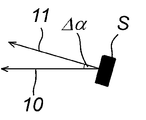
도 1은 센서 오정렬의 개략도를 도시한다.
도 2는 이동하는 차량에 장착된 오브젝트 센서에 의한 오브젝트의 검출을 도시한다.
도 3은 센서 오정렬이 가정될 때 센서에 대한 오브젝트의 상대 위치의 기하학적 관계를 도시한다.1 shows a schematic diagram of sensor misalignment.
2 shows detection of an object by an object sensor mounted on a moving vehicle.
3 shows the geometric relationship of the relative position of the object to the sensor when sensor misalignment is assumed.
도 1은 센서 부근의 오브젝트를 기록할 수 있는 오브젝트 센서(S)를 도시한다. 기록된 센서 데이터의 계산을 위해, 센서가 화살표(10)를 따라 센서의 이동 방향으로 정렬되는 것으로 가정된다. 그러나, 실제 센서 배향은 가정된 센서 정렬(10)로부터 측 방향으로 벗어나고, 화살표(11)를 통해 표현된다. 가정된 센서 정렬(10)과 실제 센서 정렬(11) 사이의 각도(Δα)는 이에 따라 방위각 에러를 나타낸다. 도시된 예에서, 오브젝트 데이터 기록은 도면 레벨에서 수행된다. 따라서 방위각 에러(Δα)는 센서(S)의 측 방향 정렬에서의 에러이다.1 shows an object sensor S capable of recording an object in the vicinity of the sensor. For calculation of the recorded sensor data, it is assumed that the sensor is aligned in the direction of movement of the sensor along the
도 2는 센서(S)가 설치되어 있는 이동하는 차량(12)에 의한 오브젝트(O)의 기록의 개략도를 도시한다. 제 1 측정 중에 센서는 위치(S1)에 있다. 오브젝트(O)는 방위각(α1) 하에 나타난다. 그러나, 센서 에러(Δα)로 인해 오브젝트는 실제로 각도(α1 + Δα) 하에 위치(O1)에 나타난다.2 shows a schematic diagram of the recording of the object O by the moving
제 2 시점에서, 차량(12)은 도 2에 도시된 중앙 위치로 더 이동했다. 정적 오브젝트(O)는 여전히 동일한 위치에 나타나지만, 그러나 센서 위치(S2)로부터 더 큰 각도(α2)로 나타난다. 그러나, 방위각 에러(Δα)로 인해, 오브젝트는 겉보기로 방위각(α2 + Δα) 하에 위치(O2)에 나타난다.At the second time point, the
제 3 측정에서, 차량(12)은 더 왼쪽으로 이동하고, 센서는 위치(S3)에 존재한다. 실제 오브젝트 위치(O)는 여기서 더 큰 각도(α3) 하에 나타난다. 제 3 측정에서 겉보기 위치(O3)는 각도(α3 + Δα) 하에 나타난다.In the third measurement, the
도 3에는 겉보기 오브젝트 위치(Oi)가 극점 추가에 의해 센서 위치(Si)로부터 어떻게 얻어지는지를 도시한다. 예를 들어 초음파 또는 레이더 펄스의 통과 시간을 측정함에 의해 또는 입체 이미지 평가에 의해 결정될 수 있는 센서(Si)와 오브젝트(O) 사이의 거리(d)를 알게 되면, 직교 좌표에서 센서와 겉보기 오브젝트 위치 사이의 거리는 다음과 같이 얻어진다.Figure 3 shows how obtained from the position sensor (S i) by adding the apparent object position (O i) the pole. Knowing the distance (d) between the sensor (S i ) and the object (O), which can be determined, for example, by measuring the transit time of ultrasound or radar pulses or by stereoscopic image evaluation, the sensor and the apparent object in Cartesian coordinates The distance between locations is obtained as follows.
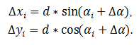
차량 이동에 따라 센서 위치(Si)가 고려되면, 오브젝트(O)의 위치는 센서(S)의 위치에 극점 추가를 수행함으로써 얻어진다:If the sensor position Si is considered according to the vehicle movement, the position of the object O is obtained by performing a pole addition to the position of the sensor S:

실제 방위각 에러(Δα)를 고려하여 결정된 오브젝트 위치(Oi)로부터 오브젝트 위치(O)가 결정되면, 센서가 이동할 때, 정적 오브젝트의 오브젝트 위치는 변하지 않아야 한다. 가정된 방위각 에러(Δα)가 실제 방위각 에러에 대응하지 않으면, 계산된 실제 오브젝트 위치(O)는 실제 오브젝트 위치(O)와 다소 큰 차이를 갖는데, 즉, 값(OI)으로부터 역 계산된 오브젝트 위치들은 상이하다. 예를 들어 복수의 기록된 오브젝트(O)에 대한 헬메르트(Helmert)의 포인트 에러의 합과 같이, 이로부터 결정된 에러 변수로부터, 이 경우 실제 방위각 에러(Δα)는 적절한 최소화/최적화 방법에 의해 결정될 수 있다.When the object position O is determined from the object position O i determined in consideration of the actual azimuth error Δα, when the sensor moves, the object position of the static object should not change. If the assumed azimuth error (Δα) does not correspond to the actual azimuth error, the calculated real object position (O) has a slightly larger difference from the real object position (O), that is, an object inversely calculated from the value O I The locations are different. From the error variable determined therefrom, for example the sum of Helmert's point errors for a plurality of recorded objects O, the actual azimuth error Δα in this case will be determined by an appropriate minimization/optimization method. Can.
따라서, 각도(Δα)를 스마트하게 변화시키고, 오브젝트 위치를 새로 계산하고, 헬메르트의 포인트 에러의 합을 결정함으로써, 적절한 종료 기준을 사용하여 의사 방위각이 결정될 수 있다. 예를 들어 종료 기준은 Δα의 점점 작아지는 변화로 인해 헬메르트의 포인트 에러의 합은 더 이상 크게 변하지 않는다는 것을 포함할 수 있다. 예를 들어, 가능한 한 최대 방위각 에러가 2°라고 가정하면, 값들 Δα = 2°, Δα = 0° 및 Δα = -2°에 대한 헬메르트의 포인트 에러의 합이 계산될 수 있다. 다음 반복 단계에서, 헬메르트의 포인트 에러의 합은 값들 Δα = 1° 및 Δα = -1°에 대해 계산된다. Δα = 1°에 대한 헬메르트의 포인트 에러의 합이 더 작으면, 다음 반복 단계에서 Δα = 0.5° 및 Δα = 1.5°로 계속 계산된다. 이것은 헬메르트의 포인트 에러의 합이 크게 변하지 않아서 이에 따라 올바른 의사 방위각에 접근할 때까지 계속된다.Thus, by changing the angle Δα smartly, calculating a new object position, and determining the sum of Helmert's point errors, the pseudo azimuth angle can be determined using the appropriate termination criteria. For example, the termination criterion may include that the sum of the points error of Helmert no longer changes significantly due to the increasingly small change in Δα. For example, assuming that the maximum possible azimuth error is 2°, the sum of Helmert's point errors for the values Δα = 2°, Δα = 0° and Δα = -2° can be calculated. In the next iteration step, the sum of the points error of Helmert is calculated for the values Δα = 1° and Δα = -1°. If the sum of Helmert's point errors for Δα = 1° is smaller, it is still calculated as Δα = 0.5° and Δα = 1.5° in the next iteration step. This continues until the sum of Helmert's point errors does not change significantly, thus approaching the correct pseudo azimuth.
대안적으로, 최적화 문제는
또한, 다른 각도에 의해 실제로 야기되는 에러의 비율이 센서 좌표계의 상이한 위치에서 크게 상이할 수도 있다. 이것은 이론적으로 센서 좌표계에서 다른 영역에 대한 의사 방위각을 예를 들어, 보다 정확하고 보다 안정적으로 유지될 수 있는 임의의 큰 매트릭스의 형태로 결정할 수 있다는 것을 의미한다.In addition, the percentage of errors actually caused by different angles may differ significantly at different locations in the sensor coordinate system. This means that, in theory, the pseudo-azimuth angle for different regions in the sensor coordinate system can be determined, for example, in the form of any large matrix that can be maintained more accurately and more stably.
이 방법의 가장 큰 장점은 큰 노력 없이 주행 중에 사용될 수 있다는 점이다. 또한 이는 적은 리소스를 필요로 하는 신속한 방법이다. 이는 알려진 방법이 많이 있는 경우에는 그렇지 않다. "의사 방위각"을 사용하여 계산된 오브젝트의 위치는 또한 맵핑을 위해 사용될 수 있지만, 그러나 또한 맵을 사용한 위치 결정을 위해 사용될 수도 있다. 가장 간단한 실시예에서, 상기 방법은 절대적인 교정을 제공하지 않지만, 그러나 예를 들어 사용된 교정이 적합하지 않다는 경고를 적어도 제공하기 위해 사용될 수 있다. 이로 인해 정확한 센서 데이터가 필요한 후속 애플리케이션이 제한 모드 또는 비-기능 모드로 전환될 수 있다.The main advantage of this method is that it can be used while driving without great effort. It is also a quick way to require fewer resources. This is not the case when there are many known methods. The position of the object calculated using "pseudo azimuth" can also be used for mapping, but it can also be used for positioning using the map. In the simplest embodiment, the method does not provide absolute calibration, but can be used, for example, to at least provide a warning that the calibration used is not suitable. This allows subsequent applications that require accurate sensor data to switch to restricted or non-functional mode.
10 : 화살표, 센서의 이동 방향, 가정된 센서 배향
11 : 화살표, 실제 센서 배향
12 : 차량
S : 센서
Si : 다른 센서 위치(i = 1,2,3)
O : 오브젝트
Oi : 다른 겉보기 오브젝트 위치
Δα : 방위각 에러
αi : 다른 센서 위치에서의 방위각(i = 1,2,3)10: arrow, the direction of movement of the sensor, the assumed sensor orientation
11: arrow, actual sensor orientation
12: vehicle
S: sensor
S i : Different sensor positions (i = 1,2,3)
O: Object
O i : Other apparent object position
Δα: Azimuth error
α i : Azimuth at different sensor positions (i = 1,2,3)
Claims (14)
오브젝트 센서의 이동을 기록하는 단계,
상기 오브젝트 센서의 상이한 위치들에서 상기 이동하는 오브젝트 센서에 의해 적어도 하나의 정적 오브젝트를 복수 회 검출하는 단계,
상기 오브젝트 센서의 대응하는 상기 위치에 대한 상기 정적 오브젝트의 상대 위치를 계산하는 단계,
상기 오브젝트 센서의 정렬 에러를 가정하여 상기 상대 위치로부터 상기 정적 오브젝트의 예상 위치를 계산하는 단계,
상기 예상 위치로부터 에러 변수를 계산하는 단계, 및
상기 오브젝트 센서의 상기 정렬 에러를 조정함으로써 상기 에러 변수를 최소화하는 단계
를 포함하는, 이동하는 오브젝트 센서의 정렬을 교정하기 위한 방법.A method for calibrating the alignment of a moving object sensor,
Recording the movement of the object sensor,
Detecting at least one static object multiple times by the moving object sensor at different locations of the object sensor,
Calculating a relative position of the static object with respect to the corresponding position of the object sensor,
Assuming an alignment error of the object sensor, calculating an expected position of the static object from the relative position,
Calculating an error variable from the expected position, and
Minimizing the error variable by adjusting the alignment error of the object sensor
A method for calibrating alignment of a moving object sensor, comprising:
상기 오브젝트 센서는 하나의 평면에서 상기 적어도 하나의 정적 오브젝트를 검출하는 것을 특징으로 하는 방법.According to claim 1,
And the object sensor detects the at least one static object in one plane.
상기 적어도 하나의 정적 오브젝트는 검출 평면에서 본질적으로 점 형태로 보이는 세장형 오브젝트인 것을 특징으로 하는 방법.According to claim 2,
The method of claim 1, wherein the at least one static object is an elongated object that is essentially point-shaped in the detection plane.
상기 오브젝트 센서의 상기 정렬 에러는 방위각 에러를 포함하는 것을 특징으로 하는 방법.The method according to any one of claims 1 to 3,
And the alignment error of the object sensor includes an azimuth error.
상기 에러 변수는 상기 방위각 에러를 변경함으로써 반복적으로 최소화되는 것을 특징으로 하는 방법.The method of claim 4,
And the error variable is minimized repeatedly by changing the azimuth error.
상기 에러 변수는 최적화 방법을 통해 최소화되는 것을 특징으로 하는 방법.The method of claim 4,
The error variable is characterized in that it is minimized through an optimization method.
상기 에러 변수는 헬메르트(Helmert)의 포인트 에러로부터 계산되는 것을 특징으로 하는 방법.The method according to any one of claims 1 to 3,
The error variable is calculated from the point error of Helmert (Helmert).
하나 초과의 정적 오브젝트가 기록되는 것을 특징으로 하는 방법.The method according to any one of claims 1 to 3,
A method characterized in that more than one static object is recorded.
상기 오브젝트 센서의 절대 위치가 또한 기록되는 것을 특징으로 하는 방법.The method according to any one of claims 1 to 3,
The method characterized in that the absolute position of the object sensor is also recorded.
상기 정적 오브젝트의 상기 위치들은 상기 오브젝트 센서의 상기 위치들로부터 극점 추가에 의해 계산되는 것을 특징으로 하는 방법.The method according to any one of claims 1 to 3,
And the positions of the static object are calculated by adding a pole from the positions of the object sensor.
상기 정적 오브젝트의 에러 수정 위치가 계산되는 것을 특징으로 하는 방법.The method of claim 10,
A method characterized in that the error correction position of the static object is calculated.
상기 오브젝트 센서의 절대 위치는 상기 정적 오브젝트의 상기 에러 수정 위치 및 상기 정적 오브젝트의 알려진 절대 위치로부터 결정되는 것을 특징으로 하는 방법.The method of claim 11,
And the absolute position of the object sensor is determined from the error correction position of the static object and a known absolute position of the static object.
상기 오브젝트 센서는 레이더 센서, 초음파 센서, 레이저 센서 또는 이미지 센서를 포함하는 것을 특징으로 하는 방법.The method according to any one of claims 1 to 3,
The object sensor comprises a radar sensor, an ultrasonic sensor, a laser sensor or an image sensor.
상기 오브젝트 센서가 차량에 설치되는 것을 특징으로 하는 방법.The method according to any one of claims 1 to 3,
A method characterized in that the object sensor is installed in the vehicle.
Applications Claiming Priority (2)
| Application Number | Priority Date | Filing Date | Title |
|---|---|---|---|
| DE102018133693.4A DE102018133693B3 (en) | 2018-12-28 | 2018-12-28 | Procedure for calibrating the alignment of a moving object sensor |
| DE102018133693.4 | 2018-12-28 |
Publications (2)
| Publication Number | Publication Date |
|---|---|
| KR20200083301A true KR20200083301A (en) | 2020-07-08 |
| KR102327901B1 KR102327901B1 (en) | 2021-11-18 |
Family
ID=68886967
Family Applications (1)
| Application Number | Title | Priority Date | Filing Date |
|---|---|---|---|
| KR1020190175543A Active KR102327901B1 (en) | 2018-12-28 | 2019-12-26 | Method for calibrating the alignment of moving object sensor |
Country Status (5)
| Country | Link |
|---|---|
| US (1) | US11486988B2 (en) |
| EP (1) | EP3674744B1 (en) |
| KR (1) | KR102327901B1 (en) |
| CN (1) | CN111380573B (en) |
| DE (1) | DE102018133693B3 (en) |
Families Citing this family (9)
| Publication number | Priority date | Publication date | Assignee | Title |
|---|---|---|---|---|
| DE102018123391A1 (en) * | 2018-09-24 | 2020-03-26 | HELLA GmbH & Co. KGaA | Method for a sensor arrangement, sensor arrangement, computer program product and computer readable medium |
| DE102019214544B4 (en) * | 2019-09-24 | 2022-04-28 | Vitesco Technologies GmbH | Method and device for determining a target position of an environment sensor of a vehicle |
| DE102019216399A1 (en) * | 2019-10-24 | 2021-04-29 | Robert Bosch Gmbh | Method and device for calibrating a vehicle sensor |
| DE102019216396A1 (en) * | 2019-10-24 | 2021-04-29 | Robert Bosch Gmbh | Method and device for calibrating a vehicle sensor |
| US11402468B2 (en) * | 2019-12-30 | 2022-08-02 | Woven Planet North America, Inc. | Systems and methods for blind online calibration of radar systems on a vehicle |
| US12399012B2 (en) * | 2020-02-21 | 2025-08-26 | Canon Kabushiki Kaisha | Information processing device, information processing method, and storage medium |
| DE102020211167A1 (en) * | 2020-09-04 | 2022-03-10 | Robert Bosch Gesellschaft mit beschränkter Haftung | Robot and method for determining a distance covered by a robot |
| CN112255621B (en) * | 2020-10-09 | 2022-08-30 | 中国第一汽车股份有限公司 | Calibration method and device of vehicle sensor, electronic equipment and storage medium |
| US11967112B2 (en) * | 2022-09-07 | 2024-04-23 | AitronX Inc. | Method and apparatus for detecting calibration requirement for image sensors in vehicles |
Citations (2)
| Publication number | Priority date | Publication date | Assignee | Title |
|---|---|---|---|---|
| US20150224986A1 (en) * | 2012-09-12 | 2015-08-13 | Lucas Automotive Gmbh | Method for Operating an Environment Monitoring System for a Motor Vehicle |
| JP2017133861A (en) * | 2016-01-25 | 2017-08-03 | 三菱重工業株式会社 | System for calibrating installation angle of antenna and method for calibrating installation angle of antenna |
Family Cites Families (31)
| Publication number | Priority date | Publication date | Assignee | Title |
|---|---|---|---|---|
| US2267657A (en) | 1939-10-24 | 1941-12-23 | Boris V Korvin-Kroukovsky | Anchor |
| SE9902140L (en) | 1999-06-08 | 2000-12-09 | Celsiustech Electronics Ab | Procedure for performing radar measurements |
| US6535114B1 (en) | 2000-03-22 | 2003-03-18 | Toyota Jidosha Kabushiki Kaisha | Method and apparatus for environment recognition |
| DE10019182A1 (en) * | 2000-04-17 | 2001-10-25 | Bosch Gmbh Robert | Determining incorrect radiation characteristics of vehicle speed/distance sensor, involves detecting sensor error based on quality index from vehicle driving state and deadjustment values output by filter and trajectory regression blocks |
| DE10122664A1 (en) * | 2001-05-10 | 2002-11-14 | Ibeo Automobile Sensor Gmbh | calibration |
| JP4606861B2 (en) | 2004-12-03 | 2011-01-05 | 本田技研工業株式会社 | Vehicle state detection device |
| DE102005033237B4 (en) * | 2005-07-15 | 2007-09-20 | Siemens Ag | Method for determining and correcting misalignments and offsets of the sensors of an inertial measurement unit in a land vehicle |
| US7991550B2 (en) * | 2006-02-03 | 2011-08-02 | GM Global Technology Operations LLC | Method and apparatus for on-vehicle calibration and orientation of object-tracking systems |
| FR2908361B1 (en) * | 2006-11-10 | 2009-01-02 | Valeo Vision Sa | SYSTEM FOR THE DYNAMIC CORRECTION OF THE ORIENTATION OF A LIGHT SOURCE OF A VEHICLE AND ASSOCIATED METHOD |
| JP4849254B2 (en) | 2007-03-09 | 2012-01-11 | 村田機械株式会社 | Paper feeder |
| JP2008224352A (en) | 2007-03-12 | 2008-09-25 | Honda Motor Co Ltd | Vehicle traveling direction detection device and method |
| DE102008063328A1 (en) | 2008-12-30 | 2010-07-01 | Hella Kgaa Hueck & Co. | Method and device for determining a change in the pitch angle of a camera of a vehicle |
| DE102009046124A1 (en) | 2009-10-28 | 2011-05-05 | Ifm Electronic Gmbh | Method and apparatus for calibrating a 3D TOF camera system |
| US8843290B2 (en) * | 2010-07-22 | 2014-09-23 | Qualcomm Incorporated | Apparatus and methods for calibrating dynamic parameters of a vehicle navigation system |
| DE102010049093A1 (en) * | 2010-10-21 | 2012-04-26 | Gm Global Technology Operations Llc (N.D.Ges.D. Staates Delaware) | Method for operating at least one sensor of a vehicle and vehicle with at least one sensor |
| WO2012145818A1 (en) | 2011-04-25 | 2012-11-01 | Magna International Inc. | Method and system for dynamically calibrating vehicular cameras |
| KR101346916B1 (en) | 2011-06-22 | 2014-01-07 | 주식회사 만도 | System for Correcting Misalignment of Radar Installment Angle |
| US8930063B2 (en) | 2012-02-22 | 2015-01-06 | GM Global Technology Operations LLC | Method for determining object sensor misalignment |
| CN104395777B (en) | 2012-06-28 | 2017-04-05 | 奥托立夫开发公司 | Misalignment Handling of Vehicle Radar Sensors |
| DE102013209494A1 (en) * | 2013-05-22 | 2014-11-27 | Robert Bosch Gmbh | Method and device for determining a misalignment of a radar sensor of a vehicle |
| US10024955B2 (en) | 2014-03-28 | 2018-07-17 | GM Global Technology Operations LLC | System and method for determining of and compensating for misalignment of a sensor |
| WO2015151681A1 (en) | 2014-03-31 | 2015-10-08 | 日立オートモティブシステムズ株式会社 | Vehicle orientation detection device |
| CN106662638B (en) * | 2014-08-15 | 2019-06-25 | 罗伯特·博世有限公司 | car radar alignment |
| DE102014220687A1 (en) * | 2014-10-13 | 2016-04-14 | Continental Automotive Gmbh | Communication device for a vehicle and method for communicating |
| EP3104189B1 (en) | 2015-06-11 | 2020-09-30 | Veoneer Sweden AB | Misalignment estimation for a vehicle radar system |
| DE102015118085A1 (en) * | 2015-10-23 | 2017-04-27 | Valeo Schalter Und Sensoren Gmbh | Method for correcting an incorrect alignment of an optical sensor of a motor vehicle, computing device, driver assistance system and motor vehicle |
| DE102015119660A1 (en) * | 2015-11-13 | 2017-05-18 | Valeo Schalter Und Sensoren Gmbh | Method for calibrating a sensor of a motor vehicle for angle measurement, computing device, driver assistance system and motor vehicle |
| MY201069A (en) | 2016-02-05 | 2024-02-01 | Hfi Innovation Inc | Method and apparatus of motion compensation based on bi-directional optical flow techniques for video coding |
| US10088553B2 (en) | 2016-03-14 | 2018-10-02 | GM Global Technology Operations LLC | Method of automatic sensor pose estimation |
| CN108614256A (en) * | 2016-12-12 | 2018-10-02 | 北京行易道科技有限公司 | Calibration system and method |
| US10452067B2 (en) * | 2017-02-23 | 2019-10-22 | GM Global Technology Operations LLC | System and method for detecting improper sensor installation within a vehicle to mitigate hazards associated with object detection |
-
2018
- 2018-12-28 DE DE102018133693.4A patent/DE102018133693B3/en not_active Expired - Fee Related
-
2019
- 2019-12-11 EP EP19215439.1A patent/EP3674744B1/en active Active
- 2019-12-26 KR KR1020190175543A patent/KR102327901B1/en active Active
- 2019-12-27 US US16/728,308 patent/US11486988B2/en active Active
- 2019-12-30 CN CN201911391433.3A patent/CN111380573B/en active Active
Patent Citations (2)
| Publication number | Priority date | Publication date | Assignee | Title |
|---|---|---|---|---|
| US20150224986A1 (en) * | 2012-09-12 | 2015-08-13 | Lucas Automotive Gmbh | Method for Operating an Environment Monitoring System for a Motor Vehicle |
| JP2017133861A (en) * | 2016-01-25 | 2017-08-03 | 三菱重工業株式会社 | System for calibrating installation angle of antenna and method for calibrating installation angle of antenna |
Also Published As
| Publication number | Publication date |
|---|---|
| DE102018133693B3 (en) | 2020-06-04 |
| US11486988B2 (en) | 2022-11-01 |
| EP3674744B1 (en) | 2021-11-24 |
| US20200209369A1 (en) | 2020-07-02 |
| CN111380573A (en) | 2020-07-07 |
| KR102327901B1 (en) | 2021-11-18 |
| CN111380573B (en) | 2022-06-10 |
| EP3674744A1 (en) | 2020-07-01 |
Similar Documents
| Publication | Publication Date | Title |
|---|---|---|
| KR102327901B1 (en) | Method for calibrating the alignment of moving object sensor | |
| CN111208492B (en) | Vehicle lidar external parameter calibration method and device, computer equipment and storage medium | |
| CN110709890B (en) | Map data correction method and device | |
| RU2678960C1 (en) | Device for estimating vehicle position, method for estimating vehicle position | |
| CN112710339B (en) | Method and apparatus for calibrating vehicle sensors | |
| US12181614B2 (en) | Method for estimating correction angles in a radar sensor for motor vehicles | |
| WO2018196391A1 (en) | Method and device for calibrating external parameters of vehicle-mounted camera | |
| US11327155B2 (en) | Radar sensor misalignment detection for a vehicle | |
| US12174021B2 (en) | Measurement accuracy calculation device, self-position estimation device, control method, program and storage medium | |
| CN110766760B (en) | Method, device, equipment and storage medium for camera calibration | |
| CN113566817B (en) | Vehicle positioning method and device | |
| CN115436917B (en) | Collaborative estimation and correction of LIDAR boresight alignment error and host vehicle positioning error | |
| US11908206B2 (en) | Compensation for vertical road curvature in road geometry estimation | |
| WO2018212292A1 (en) | Information processing device, control method, program and storage medium | |
| CN110488838A (en) | A kind of interior independent navigation robot accurately repeats localization method | |
| JP2023002082A (en) | MAP UPDATE DEVICE, MAP UPDATE METHOD AND MAP UPDATE COMPUTER PROGRAM | |
| JP6819441B2 (en) | Target position estimation method and target position estimation device | |
| CN112710340B (en) | Method and apparatus for calibrating vehicle sensors | |
| US12498456B2 (en) | Method for calibrating a radar sensor | |
| CN115824591B (en) | Camera calibration and verification method and system based on video camera bellows | |
| WO2020021596A1 (en) | Vehicle position estimation device and vehicle position estimation method | |
| KR101921483B1 (en) | Method for measuring uncertainty of gnss based localization | |
| CN110764117A (en) | Method for calibrating relative position of detection robot antenna and sensor based on total station | |
| CN111258306B (en) | Vehicle positioning method and device based on imaging equipment | |
| CN118534895A (en) | A ribbon navigation positioning correction method, system and electronic equipment |
Legal Events
| Date | Code | Title | Description |
|---|---|---|---|
| A201 | Request for examination | ||
| PA0109 | Patent application |
Patent event code: PA01091R01D Comment text: Patent Application Patent event date: 20191226 |
|
| PA0201 | Request for examination | ||
| PG1501 | Laying open of application | ||
| E902 | Notification of reason for refusal | ||
| PE0902 | Notice of grounds for rejection |
Comment text: Notification of reason for refusal Patent event date: 20210420 Patent event code: PE09021S01D |
|
| E701 | Decision to grant or registration of patent right | ||
| PE0701 | Decision of registration |
Patent event code: PE07011S01D Comment text: Decision to Grant Registration Patent event date: 20211015 |
|
| GRNT | Written decision to grant | ||
| PR0701 | Registration of establishment |
Comment text: Registration of Establishment Patent event date: 20211112 Patent event code: PR07011E01D |
|
| PR1002 | Payment of registration fee |
Payment date: 20211115 End annual number: 3 Start annual number: 1 |
|
| PG1601 | Publication of registration |