KR20200083336A - Power Measuring System Using Network - Google Patents
Power Measuring System Using Network Download PDFInfo
- Publication number
- KR20200083336A KR20200083336A KR1020190176761A KR20190176761A KR20200083336A KR 20200083336 A KR20200083336 A KR 20200083336A KR 1020190176761 A KR1020190176761 A KR 1020190176761A KR 20190176761 A KR20190176761 A KR 20190176761A KR 20200083336 A KR20200083336 A KR 20200083336A
- Authority
- KR
- South Korea
- Prior art keywords
- voltage
- power
- network
- current
- time
- Prior art date
- Legal status (The legal status is an assumption and is not a legal conclusion. Google has not performed a legal analysis and makes no representation as to the accuracy of the status listed.)
- Ceased
Links
- 238000005259 measurement Methods 0.000 claims abstract description 109
- 238000000034 method Methods 0.000 claims description 6
- 230000005611 electricity Effects 0.000 abstract description 6
- 238000012544 monitoring process Methods 0.000 abstract description 4
- 238000004364 calculation method Methods 0.000 description 10
- 238000006243 chemical reaction Methods 0.000 description 4
- 238000010586 diagram Methods 0.000 description 4
- 238000012545 processing Methods 0.000 description 4
- 238000005070 sampling Methods 0.000 description 4
- 238000004422 calculation algorithm Methods 0.000 description 2
- 230000000694 effects Effects 0.000 description 2
- 239000002803 fossil fuel Substances 0.000 description 2
- 238000000691 measurement method Methods 0.000 description 2
- 238000004088 simulation Methods 0.000 description 2
- 230000001360 synchronised effect Effects 0.000 description 2
- 238000010792 warming Methods 0.000 description 2
- 238000012952 Resampling Methods 0.000 description 1
- 238000009434 installation Methods 0.000 description 1
- 238000012986 modification Methods 0.000 description 1
- 230000004048 modification Effects 0.000 description 1
- 231100000957 no side effect Toxicity 0.000 description 1
- 230000008520 organization Effects 0.000 description 1
- 238000002203 pretreatment Methods 0.000 description 1
Images




Classifications
-
- G—PHYSICS
- G01—MEASURING; TESTING
- G01R—MEASURING ELECTRIC VARIABLES; MEASURING MAGNETIC VARIABLES
- G01R22/00—Arrangements for measuring time integral of electric power or current, e.g. electricity meters
- G01R22/06—Arrangements for measuring time integral of electric power or current, e.g. electricity meters by electronic methods
- G01R22/061—Details of electronic electricity meters
- G01R22/063—Details of electronic electricity meters related to remote communication
-
- G—PHYSICS
- G01—MEASURING; TESTING
- G01R—MEASURING ELECTRIC VARIABLES; MEASURING MAGNETIC VARIABLES
- G01R21/00—Arrangements for measuring electric power or power factor
- G01R21/06—Arrangements for measuring electric power or power factor by measuring current and voltage
-
- G—PHYSICS
- G01—MEASURING; TESTING
- G01R—MEASURING ELECTRIC VARIABLES; MEASURING MAGNETIC VARIABLES
- G01R22/00—Arrangements for measuring time integral of electric power or current, e.g. electricity meters
- G01R22/06—Arrangements for measuring time integral of electric power or current, e.g. electricity meters by electronic methods
- G01R22/10—Arrangements for measuring time integral of electric power or current, e.g. electricity meters by electronic methods using digital techniques
-
- H—ELECTRICITY
- H04—ELECTRIC COMMUNICATION TECHNIQUE
- H04L—TRANSMISSION OF DIGITAL INFORMATION, e.g. TELEGRAPHIC COMMUNICATION
- H04L27/00—Modulated-carrier systems
- H04L27/0004—Modulated-carrier systems using wavelets
-
- H—ELECTRICITY
- H04—ELECTRIC COMMUNICATION TECHNIQUE
- H04L—TRANSMISSION OF DIGITAL INFORMATION, e.g. TELEGRAPHIC COMMUNICATION
- H04L69/00—Network arrangements, protocols or services independent of the application payload and not provided for in the other groups of this subclass
- H04L69/28—Timers or timing mechanisms used in protocols
-
- Y—GENERAL TAGGING OF NEW TECHNOLOGICAL DEVELOPMENTS; GENERAL TAGGING OF CROSS-SECTIONAL TECHNOLOGIES SPANNING OVER SEVERAL SECTIONS OF THE IPC; TECHNICAL SUBJECTS COVERED BY FORMER USPC CROSS-REFERENCE ART COLLECTIONS [XRACs] AND DIGESTS
- Y04—INFORMATION OR COMMUNICATION TECHNOLOGIES HAVING AN IMPACT ON OTHER TECHNOLOGY AREAS
- Y04S—SYSTEMS INTEGRATING TECHNOLOGIES RELATED TO POWER NETWORK OPERATION, COMMUNICATION OR INFORMATION TECHNOLOGIES FOR IMPROVING THE ELECTRICAL POWER GENERATION, TRANSMISSION, DISTRIBUTION, MANAGEMENT OR USAGE, i.e. SMART GRIDS
- Y04S20/00—Management or operation of end-user stationary applications or the last stages of power distribution; Controlling, monitoring or operating thereof
- Y04S20/30—Smart metering, e.g. specially adapted for remote reading
-
- Y04S20/322—
Landscapes
- Engineering & Computer Science (AREA)
- Power Engineering (AREA)
- Physics & Mathematics (AREA)
- General Physics & Mathematics (AREA)
- Computer Networks & Wireless Communication (AREA)
- Signal Processing (AREA)
- Computer Security & Cryptography (AREA)
- Remote Monitoring And Control Of Power-Distribution Networks (AREA)
Abstract
본 발명은 가정, 건물, 공장 등 전기를 사용하는 모든 기기의 전력사용을 간편하고 저렴하게 모니터링해서 에너지 관리 시스템의 전력측정 단말로 사용할 수 있는 전력측정 시스템에 관한 것으로, 보다 상세하게는 하나 또는 복수개의 장비가 연결된 분기회로의 소비전력을 측정하는 시스템으로서, 해당 분기회로에 설치된 최소한 하나의 전압측정노드와, 상기 장비마다에 설치된 전류측정노드를 포함하며, 상기 전압측정노드와 전류측정노드는 시간동기화가 가능한 네트워크를 구성하는 것을 특징으로 하는 네트워크를 이용한 전력측정 시스템에 관한 것이다. The present invention relates to a power measurement system that can be used as a power measurement terminal of an energy management system by conveniently and inexpensively monitoring power use of all devices that use electricity, such as homes, buildings, factories, and more specifically one or more. A system for measuring power consumption of a branch circuit in which four devices are connected, including at least one voltage measurement node installed in the branch circuit and a current measurement node installed in each device, wherein the voltage measurement node and the current measurement node are time It relates to a power measurement system using a network, characterized in that to configure a network capable of synchronization.
Description
본 발명은 가정, 건물, 공장 등 전기를 사용하는 모든 기기의 전력사용을 간편하고 저렴하게 모니터링해서 에너지 관리 시스템의 전력측정 단말로 사용할 수 있는 전력측정 시스템에 관한 것이다. The present invention relates to a power measurement system that can be used as a power measurement terminal of an energy management system by simply and inexpensively monitoring power use of all devices using electricity, such as a home, a building, and a factory.
지구 온난화로 인한 화석연료를 절감하고자 하는 많은 노력이 있어 왔고 많은 재생에너지가 개발되어 사용되고 있다. 그러나 원자력은 물론이고 태양광, 풍력 같은 재생에너지도 많은 부작용이 있다.There have been many efforts to reduce fossil fuels due to global warming, and many renewable energies have been developed and used. However, not only nuclear power, but also renewable energy such as solar and wind have many side effects.
자연에 부작용이 없는 유일한 대체 에너지는 에너지 절약이다. 그러나 불편을 감수하면서 전기를 사용하지 않게 하는 것은 쉽지 않다. 따라서 불편을 최소화하면서 에너지를 절약하려고 개발한 기술이 EMS(에너지 관리 시스템)이다. EMS에서 가장 기본적인 것은 각종 기기가 소모하는 전력을 정확히 측정하고 네트워크를 통해서 이를 전송하는 것이다.The only alternative energy with no side effects to nature is energy saving. However, it is not easy to avoid using electricity at the expense of inconvenience. Therefore, EMS (energy management system) is a technology developed to save energy while minimizing inconvenience. The most basic thing in EMS is to accurately measure the power consumed by various devices and transmit it through a network.
전력을 측정하기 위해서는 전압과 전류를 동시에 측정해야 하는데 전류는 변류기(CT; Current Transformer)나 로고위스키 코일(Rogowski) 같은 비접촉식 전류측정 방식이 있지만 전압의 경우는 정확성과 가격, 크기 때문에 비접촉식으로 측정하기가 힘들다. 결국 각종 기기의 소비 전력을 정확히 측정하기 위해서는 기기로 인입되는 전선의 일부를 분기해서 전력측정 디바이스로 연결해야 하기 때문에 많은 불편이 야기된다. 특히 사용자가 일반 소비자인 경우는 더욱 문제가 되며, 고가의 장비가 많은 실험실이나 공장 같은 곳은 외부에서 기기의 파워 시스템에 연결을 할 수 없는 경우도 있다.In order to measure power, voltage and current must be measured at the same time. Current is a non-contact current measurement method such as a current transformer (CT) or Rogowski, but in the case of voltage, it is measured non-contactly because of its accuracy, price, and size. Is difficult. After all, in order to accurately measure the power consumption of various devices, a part of the electric wires input to the devices must be branched and connected to the power measurement device, causing a lot of inconvenience. In particular, it is more problematic when the user is a general consumer, and in some places, such as laboratories or factories with expensive equipment, it may not be possible to connect to the power system of the device from the outside.
이러한 문제를 해결하기 위해서 가장 쉬운 방법은 기구를 통해서 해결하는 것이다. 기구 외부에는 전기 입력 소켓과 출력 소켓을 가지고 있고 내부에는 두 개의 소켓을 단순히 연결하되 분기된 전선이 전력측정 장치에 연결된 내부 구조를 가지는 것으로 사용자는 단순히 외부에서 전원 플러그만 꽂으면 된다. 이것의 극단적인 형태는 스마트 플러그라 할 수 있다. 그러나 이 경우 전원 연결부 때문에 크기가 크고 가격이 비쌀 수 밖에 없다. 또한 전류 용량별로 다양한 기구를 만들어야 하고 공장의 기기들처럼 단순히 전원 커넥터를 연결할 수 없는 경우도 많다.The easiest way to solve this problem is through an organization. It has an electrical input socket and an output socket on the outside of the appliance, and two sockets are simply connected inside, but the branched wire has an internal structure connected to the power measuring device, so the user simply plugs in the power from the outside. The extreme form of this is a smart plug. However, in this case, the size is large and the price is high due to the power connection. In addition, it is necessary to make various devices according to the current capacity, and in many cases, it is not possible to simply connect the power connector, such as equipment in a factory.
본 발명은 전술한 종래기술의 문제점을 해소하기 위하여 가정, 건물, 공장 등 전기를 사용하는 모든 기기의 전력사용을 간편하고 저렴하게 모니터링해서 에너지 관리 시스템의 전력측정 단말로 사용할 수 있는 전력측정 시스템을 제공하는 것을 목적으로 한다. The present invention provides a power measurement system that can be used as a power measurement terminal of an energy management system by simply and inexpensively monitoring the power use of all devices using electricity, such as homes, buildings, factories, etc. It is aimed at providing.
전술한 목적을 달성하기 위한 본 발명은 The present invention for achieving the above object is
하나 또는 복수개의 장비가 연결된 분기회로의 소비전력을 측정하는 시스템으로서, 해당 분기회로에 설치된 최소한 하나의 전압측정노드와, 상기 장비마다에 설치된 전류측정노드를 포함하며, 상기 전압측정노드와 전류측정노드는 시간동기화가 가능한 네트워크를 구성하는 것을 특징으로 하는 네트워크를 이용한 전력측정 시스템에 관한 것이다. A system for measuring power consumption of a branch circuit in which one or a plurality of devices are connected, comprising at least one voltage measurement node installed in the branch circuit and a current measurement node installed in each device, and measuring the voltage and current The node relates to a power measurement system using a network, characterized in that it configures a network capable of time synchronization.
이상과 같이 본 발명의 네트워크를 이용한 전력측정 시스템은 전기를 사용하는 모든 장비에서 소비전력을 측정하기 위해서 해당 장비의 소비전류를 측정하는 전류측정노드와 해당 장비에 연결된 전선이 아닌 다른 위치에서 전압을 측정하는 전압측정노드가 시간 동기화가 이루어진 네트워크로 연결되어서 전류/전압 정보를 주고 받아 전력을 측정함으로써 전압 측정을 위해 전선을 분기해야 하는 불편과 이에 따른 비용을 줄일 수 있다. As described above, in the power measuring system using the network of the present invention, in order to measure power consumption in all equipment using electricity, the current measurement node measures the current consumption of the equipment and the voltage at a location other than the wire connected to the equipment. Since the voltage measurement node to be measured is connected to a time-synchronized network, current/voltage information is exchanged to measure power, thereby reducing the inconvenience and cost associated with branching the wire for voltage measurement.
따라서 본 발명의 시스템에 의하면 집, 빌딩, 공장, 학교에서 사용하는 기기, 장비의 전력 측정이 쉽고 설치 비용이 저렴하기 때문에 EMS(에너지 관리 시스템)가 활성화 될 수 있어, 부작용이 최소화된 에너지 절약과 이로 인한 화석 연료 사용 감소를 가져오기 때문에 지구 온난화 방지에 도움이 된다.Therefore, according to the system of the present invention, energy measurement system (EMS) can be activated because it is easy to measure the power of equipment and equipment used in a house, building, factory, school, and installation cost is low. This will help reduce global warming because it will lead to reduced fossil fuel use.
소비자들의 입장에서는 투자비가 적게 들어가기 때문에 에너지 절약 비용으로 투자비를 이전 보다 더욱 빨리 회수할 수 있다.From the consumer's point of view, the investment cost is low, so the investment cost can be recovered more quickly than before.
도 1은 본 발명에 의한 네트워크를 사용한 전력측정 시스템의 구성도.
도 2는 본 발명에 의한 전력측정 시스템의 전압측정노드의 구성도.
도 3은 본 발명에 의한 전력측정 시스템의 전류측정노드의 구성도.
도 4 내지 도 6은 본 발명에 의한 네트워크 전력측정 시스템의 전력측정 예를 보여주는 개념도.1 is a block diagram of a power measurement system using a network according to the present invention.
2 is a block diagram of a voltage measurement node of the power measurement system according to the present invention.
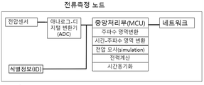
3 is a block diagram of a current measurement node of the power measurement system according to the present invention.
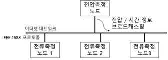
4 to 6 is a conceptual diagram showing an example of the power measurement of the network power measurement system according to the present invention.
이하 첨부된 실시예를 들어 본 발명을 보다 상세히 설명한다. 그러나 이러한 실시예는 본 발명의 기술적 사상의 내용과 범위를 쉽게 설명하기 위한 예시일 뿐, 이에 의해 본 발명의 기술적 범위가 한정되거나 변경되는 것은 아니다. 이러한 예시에 기초하여 본 발명의 기술적 사상의 범위 안에서 다양한 변형과 변경이 가능함은 당업자에게는 당연할 것이다. Hereinafter, the present invention will be described in more detail with reference to the attached examples. However, these examples are merely examples for easily explaining the contents and scope of the technical spirit of the present invention, and the technical scope of the present invention is not limited or changed thereby. It will be obvious to those skilled in the art that various modifications and changes are possible within the scope of the technical spirit of the present invention based on these examples.
본 발명은 시간동기화 네트워크로 연결된 하나의 전압측정노드와 복수의 전류측정노드를 기본으로 하는 전력측정 시스템에 관한 것이다. 즉, 본 발명은 하나 또는 복수개의 장비가 연결된 분기회로에서 장비들의 소비전력을 측정하는 시스템으로서, 해당 분기회로에 설치된 최소한 하나의 전압측정노드와, 상기 장비마다에 설치된 전류측정노드를 포함하며, 상기 전압측정노드와 전류측정노드는 시간동기화가 가능한 네트워크를 구성하는 것을 특징으로 하는 네트워크를 이용한 전력측정 시스템에 관한 것이다. 도 1에 본 발명에 의한 시스템의 일예를 도시하였다. The present invention relates to a power measurement system based on one voltage measurement node and a plurality of current measurement nodes connected by a time synchronization network. That is, the present invention is a system for measuring power consumption of equipment in a branch circuit in which one or a plurality of equipment is connected, and includes at least one voltage measuring node installed in the branch circuit and a current measuring node installed in each equipment, The voltage measurement node and the current measurement node relate to a power measurement system using a network, characterized in that it constitutes a network capable of time synchronization. 1 shows an example of a system according to the present invention.
본 발명은 다수가 시간 동기화가 이루어지는 네트워크 시스템을 구성해서 전력 계산에 필요한 그러나 자기 노드가 측정하지 않은 전류(전압)를 전송받아서 전력을 계산할 수 있도록 한 것에 특징이 있다. 분기회로에 연결된 개별 장비의 소비전력 또는 해당 분기회로 전체에 연결된 모든 장비의 소비전력을 측정할 수 있다.The present invention is characterized in that a plurality of time-synchronized network systems are configured to allow power calculation by receiving a current (voltage) that is not measured by a magnetic node, but necessary for power calculation. The power consumption of individual equipment connected to the branch circuit or the power consumption of all equipment connected to the entire branch circuit can be measured.
전압의 위상은 모든 곳에서 동일하기 때문에 전압은 한 곳에서만 측정하는 것이 편리하다. 전력측정을 하고자 하는 모든 기기(장비)에서는 전류만 측정해서 전력을 계산하는 것이다. 예를 들면 업무용으로 사용하는 컴퓨터에 연결된 인입 전선에 단순 저항을 사용한 전압 분배기(Voltage divider)를 설치해서 전압을 측정하고 각종 기기로부터 측정된 전류데이터를 전송받아 업무용 컴퓨터에서 백그라운드 소비전력을 계산할 수도 있다.Since the voltage phase is the same everywhere, it is convenient to measure the voltage in only one place. In all equipment (equipment) that wants to measure power, it measures electricity only by measuring current. For example, a voltage divider using a simple resistor can be installed on an incoming wire connected to a computer used for business purposes to measure the voltage and receive the measured current data from various devices to calculate the background power consumption at the business computer. .
즉, 전압측정노드와 전류측정노드가 서로 네트워크로 연결되어 있어야 하는 데 이때 가장 중요한 것이 시간 동기화 네트워크이다. 왜냐하면 전력계산은 전압과 전류를 동시에 측정해야 하기 때문이다. 본 발명은 최소한 하나의 전압측정노드와 다수의 전류측정노드가 시간 동기화 네트워크를 구성해서 측정된 전류 값과 전압 값을 상호 교환, 전력을 측정하는 시스템이다. 물론 시스템의 안정성을 위해서 둘 이상의 전압측정노드를 둘 수도 있지만 시스템 작동 중에는 오직 하나의 전압측정노드의 정보를 활용하는 것으로 충분하다.That is, the voltage measurement node and the current measurement node must be connected to each other in a network. The most important time is a time synchronization network. This is because power calculation must measure voltage and current simultaneously. The present invention is a system in which at least one voltage measurement node and a plurality of current measurement nodes constitute a time synchronization network to exchange measured current values and voltage values and measure power. Of course, it is possible to have more than one voltage measurement node for system stability, but it is sufficient to utilize information from only one voltage measurement node during system operation.
본 발명에서 상기 전압측정노드는 전압감지부, 감지된 전압을 디지털로 변환하는 ADC (analog-digital converter) 및 데이터를 주고받을 수 있는 네트워크부로 구성될 수 있다. 경우에 따라서는 디지털 전압 데이터에 대해 "주파수 영역 변환", "시간-주파수 영역 변환"을 수행하고 전송받은 전류데이터와 함께 전력계산을 수행하고 모든 경우에 필수적인 시간동기화를 수행하는 중앙처리부를 추가로 둘 수 있을 것이다(도 2 참조). 아래에서 보다 상세히 설명하겠지만, 상기 전압측정노드에서 전송되는 정보는 ㉮ 시간과 그 시간에 측정된 전압 정보이거나, ㉯ 전압이 0이 되는 시점과 직전 주파수 정보일 수 있다.In the present invention, the voltage measurement node may be composed of a voltage sensing unit, an analog-digital converter (ADC) that converts the sensed voltage into digital, and a network unit that can exchange data. In some cases, a central processing unit that performs "frequency domain conversion" and "time-frequency domain conversion" for digital voltage data, performs power calculation with the received current data, and performs necessary time synchronization in all cases, is added. It may be possible (see Figure 2). As will be described in more detail below, the information transmitted from the voltage measurement node may be ㉮ time and voltage information measured at the time, or may be a time point and voltage just before the ㉯ voltage becomes 0.
전압측정노드가 여러 개일 수 있으므로 전압측정노드는 자신의 식별정보(ID)를 추가로 가지며, 주고받는 데이터에 자신의 식별정보가 포함될 수 있을 것이다.Since there may be multiple voltage measurement nodes, the voltage measurement node additionally has its own identification information (ID), and its identification information may be included in data exchanged.
전압감지부는 전압분배기처럼 상용 전원을 아날로그-디지털 변환기의 입력에 맞게 신호를 조정하고, 아날로그-디지털 변환부는 감지된 전압을 디지털로 변환하는데 필요한 샘플링 레이트(sampling rate), 디지털 비트 수 등은 다른 노드들과 같거나 네트워크 프로토콜을 사용해서 설정이 가능하다.The voltage sensing unit adjusts the signal of commercial power to the input of the analog-to-digital converter like a voltage divider, and the analog-to-digital converter converts the sensed voltage to digital, such as the sampling rate and the number of digital bits. It can be set as the same or using a network protocol.
네트워크부는 유무선의 모든 네트워크가 가능하지만 이더넷처럼 정밀한 시간동기화 프로토콜이 존재하는 네트워크가 선호된다. 네트워크부는 해당 노드에서 측정한 데이터 즉, 전압측정노드인 경우는 전압, 전류측정노드인 경우는 전류를 전력계산을 위해 다른 노드 즉, 전압측정노드인 경우는 전류측정노드에, 전류측정노드인 경우는 전압측정노드에 측정된 시간 정보와 함께 전송하는 작업을 수행한다. 자체적으로 전력 계산을 할 경우는 네트워크를 통해서 다른 노드의 측정 데이터 즉, 전압측정노드인 경우는 전류측정노드로부터, 전류측정노드인 경우는 전압측정노드로부터 측정된 시간 정보와 함께 수신받아 중앙처리부에 전달한다. 또한 네트워크부는 본 시스템 외부 네트워크에서 오는 설정 명령을 처리해서 중앙처리부에 전달하는데 설정의 종류로는 아날로그-디지털 변환에 필요한 샘플링 레이트, 변환 비트 수 등 아날로그-디지털 변환부와 관련된 것, 각 노드는 전선의 길이에 따라서 전압차이가 존재할 수 있는데 그 차이를 반영한 전류측정노드의 RMS 전압 보상과 관련된 것, 전력 측정에 사용할 데이터가 변환된 데이터 그대로 즉, 시간 영역 데이터인지 주파수 영역 혹은 시간-주파수 영역으로 변환된 데이터인지 데이터 종류에 관한 것, 그리고 전력측정을 수행할 노드와 측정 데이터를 다른 노드에 전송할 노드를 지정하는 것을 포함한다.The network unit can be any wired or wireless network, but a network that has a precise time synchronization protocol such as Ethernet is preferred. The network unit measures the data measured by the corresponding node, that is, a voltage in the case of a voltage measurement node, a current in the case of a current measurement node, and a current measurement node in the case of a voltage measurement node, or a current measurement node in the case of a voltage measurement node. Transmits the measured time information to the voltage measurement node. When calculating power by itself, it receives the measurement data of other nodes through the network, that is, the time information from the current measurement node in the case of a voltage measurement node, and the voltage measurement node in the case of a current measurement node. To deliver. In addition, the network part processes the setting command from the external network of this system and transmits it to the central processing part. The voltage difference may exist depending on the length of the RMS voltage compensation of the current measurement node reflecting the difference, and the data to be used for power measurement is converted data, that is, time domain data or frequency domain or time-frequency domain. This includes specifying whether the data is data or data type, and a node to perform power measurement and a node to transmit measurement data to other nodes.
중앙처리부는 변환된 디지털 데이터를 전력측정 방식에 맞게 고속 퓨리에 연산(FFT)을 통해서 주파수 영역 혹은 웨이블릿(wavelet) 연산을 통해서 시간-주파수 영역 데이터로 변경할 수 있고 이러한 연산을 수행하지 않으면 시간 영역 데이터로 그대로 남게 된다. 이렇게 자체적으로 측정한 전압 데이터에 네트워크를 통해서 받은 전류 데이터를 사용해서 전력 계산을 수행할 수도 있고, 아니면 네트워크를 통해서 다른 노드에 전송한다. 또한 필수적인 요소로 각 노드들 간에 시간을 동기화하는 부분이 있다. 이더넷의 경우는 IEEE 1588을 사용하고 무선 네트워크처럼 명확한 정밀 시간동기화 알고리즘이 없는 경우 초 단위는 인터넷 타임 서버를 통해서 동기화하고 초 미만의 시간은 자체 클럭을 통해서 동기화할 수 있다. 본 발명처럼 전력 측정시 사용할 수 있는 유용한 시간 동기화는 전압의 주기가 60Hz 혹은 50Hz라는 것이다. 전압측정노드에서 전압이 0이 되는 시점마다 전류측정노드에 알리고 전류측정노드는 그 시점에서 시간을 동기화하고 다음 0이 되는 시점까지 자체 클럭을 사용하는 방식이다. 시간 동기화부는 동기화가 이루어진 후에는 해당 노드에서 전력을 계산할 때는 전력계산부에 시간 정보를 제공하거나 해당 노드가 전압 정보를 네트워크를 통해서 전송할 때 시간 정보도 같이 전송할 수 있도록 네트워크부에 시간정보를 제공한다.The central processing unit can convert the converted digital data into time-frequency domain data through a frequency domain or wavelet calculation through a fast Fourier operation (FFT) according to the power measurement method. Will remain. Power calculation can be performed by using the current data received through the network for the voltage data measured by itself, or it is transmitted to another node through the network. Also, an essential element is to synchronize the time between each node. In the case of Ethernet, IEEE 1588 is used, and in the absence of a clear precise time synchronization algorithm such as a wireless network, seconds can be synchronized through an Internet time server and sub-seconds can be synchronized through its own clock. A useful time synchronization that can be used for power measurement, such as the present invention, is that the voltage period is 60 Hz or 50 Hz. In the voltage measurement node, the current measurement node is notified every time the voltage becomes 0, and the current measurement node synchronizes the time at that time and uses its own clock until the next zero. After synchronization, the time synchronization unit provides time information to the power calculation unit when calculating power at the corresponding node or to the network unit so that time information can be transmitted when the corresponding node transmits voltage information through the network. .
본 발명에서 상기 전류측정노드는 전류감지부, 감지된 전류를 디지털로 변환하는 ADC 및 데이터를 주고받을 수 있는 네트워크로 구성될 수 있다. 경우에 따라서는 디지털 전류 데이터에 대해 "주파수 영역 변환", "시간-주파수 영역 변환"을 수행하고 전압 변화를 모사(simulation)하고 이렇게 추정된 전압이나 전송받은 전압데이터와 함께 전력계산을 수행하고 모든 경우에 필수적인 시간동기화를 수행하는 중앙처리부를 추가로 둘 수 있을 것이다(도 3 참조). 아래에서 보다 상세히 설명하겠지만, 상기 전류측정노드에서 전송되는 정보는 ㉮ 시간과 그 시간에 측정된 전류 정보이거나, ㉯ 시간과 그 시간에 측정된 전류 정보 및 상기 전류측정노드의 식별정보(ID)일 수 있다. ㉯의 경우 측정된 개별 장비에 대한 소비전력이 어떤 장비의 소비전력인지 확인하는데 활용될 수 있다.In the present invention, the current measurement node may be composed of a current sensing unit, an ADC that converts the sensed current into digital, and a network that can exchange data. In some cases, "frequency domain conversion" and "time-frequency domain conversion" are performed on digital current data, voltage changes are simulated, and power calculation is performed with the estimated voltage or the received voltage data. In this case, a central processing unit for performing essential time synchronization may be additionally provided (see FIG. 3). As will be described in more detail below, the information transmitted from the current measurement node is ㉮ time and current information measured at that time, or ㉯ time and current information measured at the time and identification information (ID) of the current measurement node. Can. In the case of ㉯, it can be used to check which equipment consumed power is measured.
전압 대신에 전류라는 점을 제외하면 전류측정노드의 각 구성은 상기 전압측정노드의 것과 동일할 수 있다. 다른 점은, 전송받은 전압데이터들을 샘플링 이론에 따라서 원래의 신호로 복원하고 전류센서 노드의 샘플링과 일치하게 resampling하는 전압모사(simulation) 부분이다. 전류측정노드와 동일한 샘플링 레이트의 시간 정보가 포함된 전압 데이터를 전송받으면 상관없지만, 그렇지 않고 전류측정 값보다 적은 수의 샘플을 받을 경우 이와 같은 전처리가 필요하다. 극단적인 예는 상기에 기술한대로 전압이 0이되는 시점과 직전 주파수 정보만 전송받을 경우로서 상대적으로 오차는 크겠지만 전압을 정현파로 가정하고 정해진 시간에 전압 데이터를 추정할 수 있다.Each configuration of the current measurement node may be the same as that of the voltage measurement node, except that it is current instead of voltage. The difference is the voltage simulation part that restores the transmitted voltage data to the original signal according to the sampling theory and resampling in accordance with the sampling of the current sensor node. It does not matter if the voltage data containing the time information of the same sampling rate as the current measurement node is transmitted, but otherwise, such a pre-treatment is necessary when receiving a number of samples less than the current measurement value. In the extreme example, as described above, when only voltage information when the voltage becomes 0 and immediately before the frequency information is transmitted, the error may be relatively large, but voltage data can be estimated at a predetermined time by assuming that the voltage is a sinusoidal wave.
한편, 본 발명에서는 각 개별장비 또는 장비 전체의 소비전력을 원격지에서 실시간으로 모니터링이 가능하도록 할 수 있다. 이를 위해, 상기 네트워크에 연결되어 상기 전압측정노드 및 전류측정노드로부터의 정보를 전송받아 분기회로에 연결된 개별 장비의 소비전력 또는 해당 분기회로 전체의 소비전력을 계산하고 저장하고 출력하는 단말기를 추가로 포함할 수 있다. 이하에서는 '단말기'를 컴퓨터로 단순화하여 설명한다.On the other hand, in the present invention, it is possible to enable real-time monitoring of power consumption of each individual equipment or the entire equipment at a remote location. To this end, a terminal that is connected to the network, receives information from the voltage measurement node and the current measurement node, and calculates, stores, and outputs power consumption of individual equipment connected to the branch circuit or power consumption of the entire branch circuit. It can contain. Hereinafter, the'terminal' will be briefly described with a computer.
전력 계산은 전압측정노드나 전류측정노드에서 수행할 수 있기 때문에 컴퓨터의 경우는 필수적인 요소는 아니지만 업무용 컴퓨터를 전력 계산에 사용하면 각 전압측정노드나 전류측정노드는 데이터만 전송하면 되기 때문에 가격이 저렴해지는 효과가 있다. Since the power calculation can be performed at the voltage measurement node or the current measurement node, it is not an essential element in the case of a computer, but when a business computer is used for power calculation, each voltage measurement node or current measurement node only needs to transmit data, so it is inexpensive. It has an effect.
이상과 같은 본 발명에 의한 네트워크를 이용한 전력 측정 시스템의 작동 예를 도 4, 5, 6을 참조하면서 설명한다.An operation example of the power measurement system using the network according to the present invention as described above will be described with reference to FIGS. 4, 5 and 6.
도 4의 경우는 전류측정노드가 전압 데이터와 시간정보를 받아서 전력을 측정하는 경우로서 네트워크의 모든 측정 노드는 전원이 인가되면 IEEE 1588 시간동기화 알고리즘을 수행해서 다른 노드와 시간 동기화를 수행한다. 그 다음에는 외부 네트워크에서 설정 정보를 받아서 설정을 수행하되 이 실시예의 경우는 전압측정노드에서 측정된 전압과 측정 시간을 전류 측정노드로 브로드캐스팅을 통해서 일괄적으로 전송하는 방식으로 설정된 경우이다.In the case of FIG. 4, the current measurement node receives voltage data and time information to measure power, and all measurement nodes in the network perform time synchronization with other nodes by performing an IEEE 1588 time synchronization algorithm when power is applied. Next, the configuration is performed by receiving configuration information from an external network, but in this embodiment, the voltage and measurement time measured by the voltage measurement node are set in a manner of transmitting through the broadcasting to the current measurement node.
그 후에 전압측정노드는 측정된 전압을 측정된 시간 정보와 함께 브로드캐스팅을 수행해서 모든 전류노드에 전송한다. 전류측정노드는 이렇게 받은 전압 데이터를 사용해서 설정시 정해진 바에 따라 전력측정을 수행한다.After that, the voltage measurement node broadcasts the measured voltage along with the measured time information and transmits it to all current nodes. The current measurement node uses the received voltage data to perform power measurement according to the setting.
도 5의 경우는 동기화와 설정을 수행하는 것까지는 도 4와 같으나 전압측정노드가 1개가 아니라 2개인 경우이고, 전류측정노드는 각각 다른 전압측정노드와 연관이 되는 경우로서 전류측정노드가 측정된 전류 값을 측정된 시간 정보와 함께 연관된 전압측정노드에 보내는 경우이다. 그 후에 전압측정노드는 수신한 전류측정값과 시간 정보를 이용해서 설정시 정해진 바에 따라 전력측정을 수행한다.In the case of FIG. 5, it is the same as in FIG. 4 until the synchronization and setting are performed, but the voltage measurement nodes are two instead of one, and the current measurement nodes are associated with different voltage measurement nodes, and the current measurement nodes are measured. This is when the current value is sent to the associated voltage measurement node along with the measured time information. Thereafter, the voltage measurement node performs power measurement according to a predetermined value when setting using the received current measurement value and time information.
도 6의 경우는 시간동기화를 수행하는 것이 다른 방법으로서 무선네트워크처럼 정밀한 시간 동기화가 없는 경우 유용하다. 전원이 인가되고 시간 동기화 프로토콜이 없으면 각 노드는 외부로부터 시간 동기화에 관한 설정 값을 받는다. 여기서는 전압의 주파수가 거의 일정하다는 점을 이용해서 전압측정노드는 전압이 0이 되는 시점을 직전 주파수 정보와 함께 전류측정노드에 전송하고 전류측정노드는 전압을 수신받은 주파수 정보를 사용하고 전압 형태는 정현파를 가정해서 시간에 따른 전압을 모사(simulation)하고 자신이 측정한 전류 값들을 함께 사용해서 전력을 계산한다.In the case of FIG. 6, performing time synchronization is another method and is useful when there is no precise time synchronization like a wireless network. When power is applied and there is no time synchronization protocol, each node receives a setting value for time synchronization from the outside. Here, by using the fact that the frequency of the voltage is almost constant, the voltage measurement node transmits the time when the voltage becomes 0 to the current measurement node along with the previous frequency information, and the current measurement node uses the received frequency information of the voltage and the voltage form is Assuming a sinusoidal wave, it simulates the voltage over time (simulation) and calculates the power using the current values measured together.
Claims (5)
해당 분기회로에 설치된 최소한 하나의 전압측정노드와, 상기 장비마다에 설치된 전류측정노드를 포함하며,
상기 전압측정노드와 전류측정노드는 시간동기화가 가능한 네트워크를 구성하는 것을 특징으로 하는 네트워크를 이용한 전력측정 시스템.
A system that measures the power consumption of branch circuits connected to one or more devices,
It includes at least one voltage measurement node installed in the branch circuit, and a current measurement node installed in each of the equipment,
The voltage measurement node and the current measurement node is a power measurement system using a network, characterized in that it comprises a network capable of time synchronization.
상기 소비전력은 분기회로에 연결된 개별 장비의 소비전력 또는 해당 분기회로 전체의 소비전력인 것을 특징으로 하는 네트워크를 이용한 전력측정 시스템.
The method according to claim 1,
The power consumption is a power measurement system using a network, characterized in that the power consumption of the individual equipment connected to the branch circuit or the entire branch circuit.
상기 전압측정노드에서 전송되는 정보는
시간과 그 시간에 측정된 전압 정보이거나,
전압이 0이 되는 시점과 직전 주파수 정보인 것을 특징으로 하는 네트워크를 이용한 전력측정 시스템.
The method according to claim 1 or 2,
Information transmitted from the voltage measurement node
Time and voltage information measured at that time, or
A power measurement system using a network, characterized in that the voltage is 0 and the frequency information immediately before.
상기 전류측정노드에서 전송되는 정보는
시간과 그 시간에 측정된 전류 정보이거나,
시간과 그 시간에 측정된 전류 정보 및 상기 전류측정노드가 설치된 장비 정보인 것을 특징으로 하는 네트워크를 이용한 전력측정 시스템.
The method according to claim 1 or 2,
Information transmitted from the current measurement node
Time and current information measured at that time, or
Power measurement system using a network, characterized in that the current information measured at the time and the time and equipment information on which the current measurement node is installed.
상기 네트워크에 연결되어 상기 전압측정노드 및 전류측정노드로부터의 정보를 전송받아 분기회로에 연결된 개별 장비의 소비전력 또는 해당 분기회로 전체의 소비전력을 계산하고 저장하고 출력하는 단말기를 추가로 포함하는 것을 특징으로 하는 네트워크를 이용한 전력측정 시스템.The method according to claim 4,
It further comprises a terminal connected to the network to receive information from the voltage measurement node and the current measurement node to calculate, store and output power consumption of individual equipment connected to the branch circuit or power consumption of the entire branch circuit. Power measurement system using a network.
Applications Claiming Priority (2)
| Application Number | Priority Date | Filing Date | Title |
|---|---|---|---|
| KR20180171439 | 2018-12-28 | ||
| KR1020180171439 | 2018-12-28 |
Publications (1)
| Publication Number | Publication Date |
|---|---|
| KR20200083336A true KR20200083336A (en) | 2020-07-08 |
Family
ID=71601022
Family Applications (1)
| Application Number | Title | Priority Date | Filing Date |
|---|---|---|---|
| KR1020190176761A Ceased KR20200083336A (en) | 2018-12-28 | 2019-12-27 | Power Measuring System Using Network |
Country Status (1)
| Country | Link |
|---|---|
| KR (1) | KR20200083336A (en) |
Citations (2)
| Publication number | Priority date | Publication date | Assignee | Title |
|---|---|---|---|---|
| KR101629309B1 (en) | 2009-11-04 | 2016-06-10 | 엘지전자 주식회사 | An Energy Mangement System, A Control method Thereof And An Electric appliance having An Energy Management Function |
| KR20180088165A (en) | 2017-01-26 | 2018-08-03 | 엘지전자 주식회사 | Energy management device and operating method thereof |
-
2019
- 2019-12-27 KR KR1020190176761A patent/KR20200083336A/en not_active Ceased
Patent Citations (2)
| Publication number | Priority date | Publication date | Assignee | Title |
|---|---|---|---|---|
| KR101629309B1 (en) | 2009-11-04 | 2016-06-10 | 엘지전자 주식회사 | An Energy Mangement System, A Control method Thereof And An Electric appliance having An Energy Management Function |
| KR20180088165A (en) | 2017-01-26 | 2018-08-03 | 엘지전자 주식회사 | Energy management device and operating method thereof |
Similar Documents
| Publication | Publication Date | Title |
|---|---|---|
| Morales-Velazquez et al. | Smart sensor network for power quality monitoring in electrical installations | |
| Thakare et al. | Implementation of an energy monitoring and control device based on IoT | |
| Alulema et al. | An IoT-based remote monitoring system for electrical power consumption via web-application | |
| US20130024149A1 (en) | Identification of electrical grid phase information for end-points in a grid network | |
| US12553927B2 (en) | Methods, systems and devices for monitoring power consumption and generation | |
| JP2023052439A (en) | Measuring device, time information providing device, measuring device control method, time information providing control method, measuring device control program, and time information providing control program | |
| Balsamo et al. | Non-intrusive zigbee power meter for load monitoring in smart buildings | |
| KR101529476B1 (en) | Insulation resistance monitoring system of solar power module string | |
| Campbell et al. | Gemini: A non-invasive, energy-harvesting true power meter | |
| WO2013121628A1 (en) | Detection device, detection method, and detection system | |
| US20110006756A1 (en) | Power measurement system, method and/or units | |
| Kotsilitis et al. | A versatile, low-cost monitoring device suitable for non-intrusive load monitoring research purposes | |
| Apse-Apsitis et al. | Bidirectional DC/AC energy flow measurement | |
| US8589095B2 (en) | Power measuring device | |
| JP6436329B2 (en) | Distributed power supply state detection program, recording medium, monitoring terminal, and communication device | |
| US20120313619A1 (en) | Current measuring apparatus | |
| Brunelli et al. | Non-invasive voltage measurement in a three-phase autonomous meter | |
| CN109387697A (en) | Wireless phase measurement device, method for synchronizing time and wireless Method for Phase Difference Measurement | |
| CN102466789B (en) | Photoelectric current transformer stability test device and method | |
| Sanchez et al. | Monitoring and remote control of energy consumption by WiFi networks | |
| Krishna et al. | Real time monitoring of solar micro grid installations; discussion on three year performance analysis and system black out modelling | |
| Sium et al. | IoT based smart energy monitoring and warning system | |
| JP2016090447A (en) | Power measuring apparatus and power measuring system | |
| US20130151184A1 (en) | Meter Device | |
| Campbell et al. | From Energy Audits to Monitoring Megawatt Loads: A Flexible and Deployable Power Metering System |
Legal Events
| Date | Code | Title | Description |
|---|---|---|---|
| PA0109 | Patent application |
Patent event code: PA01091R01D Comment text: Patent Application Patent event date: 20191227 |
|
| PA0201 | Request for examination | ||
| PG1501 | Laying open of application | ||
| E902 | Notification of reason for refusal | ||
| PE0902 | Notice of grounds for rejection |
Comment text: Notification of reason for refusal Patent event date: 20210316 Patent event code: PE09021S01D |
|
| E902 | Notification of reason for refusal | ||
| PE0902 | Notice of grounds for rejection |
Comment text: Notification of reason for refusal Patent event date: 20210927 Patent event code: PE09021S01D |
|
| E601 | Decision to refuse application | ||
| PE0601 | Decision on rejection of patent |
Patent event date: 20211208 Comment text: Decision to Refuse Application Patent event code: PE06012S01D Patent event date: 20210927 Comment text: Notification of reason for refusal Patent event code: PE06011S01I Patent event date: 20210316 Comment text: Notification of reason for refusal Patent event code: PE06011S01I |