KR20200085616A - Battery module, and battery pack including the same - Google Patents
Battery module, and battery pack including the same Download PDFInfo
- Publication number
- KR20200085616A KR20200085616A KR1020190001978A KR20190001978A KR20200085616A KR 20200085616 A KR20200085616 A KR 20200085616A KR 1020190001978 A KR1020190001978 A KR 1020190001978A KR 20190001978 A KR20190001978 A KR 20190001978A KR 20200085616 A KR20200085616 A KR 20200085616A
- Authority
- KR
- South Korea
- Prior art keywords
- heat transfer
- housing
- battery module
- battery
- transfer unit
- Prior art date
- Legal status (The legal status is an assumption and is not a legal conclusion. Google has not performed a legal analysis and makes no representation as to the accuracy of the status listed.)
- Granted
Links
Images


Classifications
-
- H—ELECTRICITY
- H01—ELECTRIC ELEMENTS
- H01M—PROCESSES OR MEANS, e.g. BATTERIES, FOR THE DIRECT CONVERSION OF CHEMICAL ENERGY INTO ELECTRICAL ENERGY
- H01M10/00—Secondary cells; Manufacture thereof
- H01M10/60—Heating or cooling; Temperature control
- H01M10/65—Means for temperature control structurally associated with the cells
- H01M10/655—Solid structures for heat exchange or heat conduction
- H01M10/6554—Rods or plates
-
- H—ELECTRICITY
- H01—ELECTRIC ELEMENTS
- H01M—PROCESSES OR MEANS, e.g. BATTERIES, FOR THE DIRECT CONVERSION OF CHEMICAL ENERGY INTO ELECTRICAL ENERGY
- H01M10/00—Secondary cells; Manufacture thereof
- H01M10/60—Heating or cooling; Temperature control
- H01M10/65—Means for temperature control structurally associated with the cells
- H01M10/655—Solid structures for heat exchange or heat conduction
-
- H—ELECTRICITY
- H01—ELECTRIC ELEMENTS
- H01M—PROCESSES OR MEANS, e.g. BATTERIES, FOR THE DIRECT CONVERSION OF CHEMICAL ENERGY INTO ELECTRICAL ENERGY
- H01M10/00—Secondary cells; Manufacture thereof
- H01M10/60—Heating or cooling; Temperature control
- H01M10/61—Types of temperature control
- H01M10/613—Cooling or keeping cold
-
- H—ELECTRICITY
- H01—ELECTRIC ELEMENTS
- H01M—PROCESSES OR MEANS, e.g. BATTERIES, FOR THE DIRECT CONVERSION OF CHEMICAL ENERGY INTO ELECTRICAL ENERGY
- H01M10/00—Secondary cells; Manufacture thereof
- H01M10/60—Heating or cooling; Temperature control
- H01M10/62—Heating or cooling; Temperature control specially adapted for specific applications
- H01M10/625—Vehicles
-
- H—ELECTRICITY
- H01—ELECTRIC ELEMENTS
- H01M—PROCESSES OR MEANS, e.g. BATTERIES, FOR THE DIRECT CONVERSION OF CHEMICAL ENERGY INTO ELECTRICAL ENERGY
- H01M10/00—Secondary cells; Manufacture thereof
- H01M10/60—Heating or cooling; Temperature control
- H01M10/64—Heating or cooling; Temperature control characterised by the shape of the cells
-
- H—ELECTRICITY
- H01—ELECTRIC ELEMENTS
- H01M—PROCESSES OR MEANS, e.g. BATTERIES, FOR THE DIRECT CONVERSION OF CHEMICAL ENERGY INTO ELECTRICAL ENERGY
- H01M10/00—Secondary cells; Manufacture thereof
- H01M10/60—Heating or cooling; Temperature control
- H01M10/65—Means for temperature control structurally associated with the cells
- H01M10/653—Means for temperature control structurally associated with the cells characterised by electrically insulating or thermally conductive materials
-
- H01M2/1061—
-
- H01M2/1077—
-
- H—ELECTRICITY
- H01—ELECTRIC ELEMENTS
- H01M—PROCESSES OR MEANS, e.g. BATTERIES, FOR THE DIRECT CONVERSION OF CHEMICAL ENERGY INTO ELECTRICAL ENERGY
- H01M50/00—Constructional details or processes of manufacture of the non-active parts of electrochemical cells other than fuel cells, e.g. hybrid cells
- H01M50/20—Mountings; Secondary casings or frames; Racks, modules or packs; Suspension devices; Shock absorbers; Transport or carrying devices; Holders
- H01M50/204—Racks, modules or packs for multiple batteries or multiple cells
- H01M50/207—Racks, modules or packs for multiple batteries or multiple cells characterised by their shape
- H01M50/209—Racks, modules or packs for multiple batteries or multiple cells characterised by their shape adapted for prismatic or rectangular cells
-
- H—ELECTRICITY
- H01—ELECTRIC ELEMENTS
- H01M—PROCESSES OR MEANS, e.g. BATTERIES, FOR THE DIRECT CONVERSION OF CHEMICAL ENERGY INTO ELECTRICAL ENERGY
- H01M50/00—Constructional details or processes of manufacture of the non-active parts of electrochemical cells other than fuel cells, e.g. hybrid cells
- H01M50/20—Mountings; Secondary casings or frames; Racks, modules or packs; Suspension devices; Shock absorbers; Transport or carrying devices; Holders
- H01M50/233—Mountings; Secondary casings or frames; Racks, modules or packs; Suspension devices; Shock absorbers; Transport or carrying devices; Holders characterised by physical properties of casings or racks, e.g. dimensions
- H01M50/24—Mountings; Secondary casings or frames; Racks, modules or packs; Suspension devices; Shock absorbers; Transport or carrying devices; Holders characterised by physical properties of casings or racks, e.g. dimensions adapted for protecting batteries from their environment, e.g. from corrosion
-
- H—ELECTRICITY
- H01—ELECTRIC ELEMENTS
- H01M—PROCESSES OR MEANS, e.g. BATTERIES, FOR THE DIRECT CONVERSION OF CHEMICAL ENERGY INTO ELECTRICAL ENERGY
- H01M10/00—Secondary cells; Manufacture thereof
- H01M10/60—Heating or cooling; Temperature control
- H01M10/65—Means for temperature control structurally associated with the cells
- H01M10/655—Solid structures for heat exchange or heat conduction
- H01M10/6556—Solid parts with flow channel passages or pipes for heat exchange
-
- H—ELECTRICITY
- H01—ELECTRIC ELEMENTS
- H01M—PROCESSES OR MEANS, e.g. BATTERIES, FOR THE DIRECT CONVERSION OF CHEMICAL ENERGY INTO ELECTRICAL ENERGY
- H01M2220/00—Batteries for particular applications
- H01M2220/20—Batteries in motive systems, e.g. vehicle, ship, plane
-
- Y—GENERAL TAGGING OF NEW TECHNOLOGICAL DEVELOPMENTS; GENERAL TAGGING OF CROSS-SECTIONAL TECHNOLOGIES SPANNING OVER SEVERAL SECTIONS OF THE IPC; TECHNICAL SUBJECTS COVERED BY FORMER USPC CROSS-REFERENCE ART COLLECTIONS [XRACs] AND DIGESTS
- Y02—TECHNOLOGIES OR APPLICATIONS FOR MITIGATION OR ADAPTATION AGAINST CLIMATE CHANGE
- Y02E—REDUCTION OF GREENHOUSE GAS [GHG] EMISSIONS, RELATED TO ENERGY GENERATION, TRANSMISSION OR DISTRIBUTION
- Y02E60/00—Enabling technologies; Technologies with a potential or indirect contribution to GHG emissions mitigation
- Y02E60/10—Energy storage using batteries
Landscapes
- Chemical & Material Sciences (AREA)
- Chemical Kinetics & Catalysis (AREA)
- Electrochemistry (AREA)
- General Chemical & Material Sciences (AREA)
- Engineering & Computer Science (AREA)
- Manufacturing & Machinery (AREA)
- Battery Mounting, Suspending (AREA)
- Secondary Cells (AREA)
Abstract
본 발명의 일 실시예에 따른 전지 모듈은, 복수의 전지셀, 상기 복수의 전지셀을 수용하는 하우징, 상기 하우징의 외측면에 배치된 냉각부를 포함하는 전지 모듈로서, 상기 복수의 전지셀의 일측에 접하도록, 상기 하우징의 내측면에 형성되는 제1 열전달부를 포함하며, 상기 하우징은 상기 복수의 전지셀의 굴곡진 형태를 따라 굴곡진 부분을 가질 수 있다.A battery module according to an embodiment of the present invention is a battery module including a plurality of battery cells, a housing accommodating the plurality of battery cells, and a cooling unit disposed on an outer surface of the housing, one side of the plurality of battery cells In contact with, it includes a first heat transfer portion formed on the inner surface of the housing, the housing may have a curved portion along the curved shape of the plurality of battery cells.
Description
본 발명은 전지 모듈, 및 이를 포함하는 전지팩에 관한 것으로서, 냉각 성능을 향상시키는 전지 모듈, 및 이를 포함하는 전지팩에 관한 것이다.The present invention relates to a battery module, and a battery pack including the same, and relates to a battery module that improves cooling performance, and a battery pack including the same.
현대 사회에서는 휴대폰, 노트북, 캠코더, 디지털 카메라 등의 휴대형 기기의 사용이 일상화되면서, 상기와 같은 모바일 기기와 관련된 분야의 기술에 대한 개발이 활발해지고 있다. 또한, 충방전이 가능한 이차 전지는 화석 연료를 사용하는 기존의 가솔린 차량 등의 대기 오염 등을 해결하기 위한 방안으로, 전기 자동차(EV), 하이브리드 전기자동차(HEV), 플러그-인 하이브리드 전기자동차(P-HEV) 등의 동력원으로 이용되고 있는바, 이차 전지에 대한 개발의 필요성이 높아지고 있다.In the modern society, as the use of portable devices such as mobile phones, notebook computers, camcorders, and digital cameras becomes common, development of technologies related to the mobile devices as described above is becoming active. In addition, the secondary battery capable of charging and discharging is a method for solving air pollution, such as existing gasoline vehicles using fossil fuel, electric vehicles (EV), hybrid electric vehicles (HEV), and plug-in hybrid electric vehicles ( P-HEV) has been used as a power source, and the need for development of secondary batteries is increasing.
소형 기기들에 이용되는 이차 전지의 경우, 2-3개의 전지셀들이 배치되나, 자동차 등과 같은 중대형 디바이스에 이용되는 이차 전지의 경우는, 다수의 전지셀을 전기적으로 연결한 전지 모듈이 이용된다.In the case of a secondary battery used in small devices, 2-3 battery cells are arranged, but in the case of a secondary battery used in a medium- or large-sized device such as an automobile, a battery module in which a plurality of battery cells are electrically connected is used.
이와 같은 중대형 디바이스에 이용되는 전지 모듈의 경우, 디바이스에서 요구되는 특정 값 이상의 용량을 제공하기 위하여, 다수의 전지셀들을 직렬 방식으로 전기적으로 연결하여 이용되고 있으며, 이 경우, 다수의 전지셀들을 연결하는 방식, 고정시키는 방식 등에 따라 이차 전지 자체의 안정성이 상이해진다.In the case of a battery module used in such a medium-to-large-sized device, in order to provide a capacity greater than a specific value required by the device, a plurality of battery cells are electrically connected in series, and in this case, a plurality of battery cells are connected The stability of the secondary battery itself varies depending on the method, the method of fixing, and the like.
특히, 이와 같이 용량을 증가시킨 이차 전지에서는, 전지의 과열로 인한 문제가 발생하는 것을 방지하기 위하여 전지를 냉각시키는 방식이 중요하다. 전지 내부의 열을 효율적으로 방열시킬 필요가 있으며, 이차 전지의 열을 방열시키기 위한 것으로서, 이차 전지와 결합되는 면에 열 인터페이스 물질(TIM: Thermal Interface Material)을 도포하는 방법이 있다.In particular, in the secondary battery having increased capacity in this way, it is important to cool the battery in order to prevent a problem caused by overheating of the battery. It is necessary to efficiently dissipate heat inside the battery, and for dissipating heat of the secondary battery, there is a method of applying a thermal interface material (TIM) to a surface coupled with the secondary battery.
열 인터페이스 물질(TIM: Thermal Interface Material)이란, 열 계면 재료라고도 하며, 열이 전달되는 경로에 있어서, 상기 재료를 각각의 면과 면 사이에 채워 넣음으로써 열이 전달되는 면의 접촉 면적을 조절하여, 최종적으로는 열 전달의 경로를 조절함으로써, 열 저항을 조절하는 것이다.Thermal interface material (TIM) is also referred to as a thermal interface material, and in a path for transferring heat, by filling the material between each surface and each surface to control the contact area of the surface to which heat is transferred. , Finally, by adjusting the path of heat transfer, it is to control the heat resistance.
이와 같은 이차 전지 내부 과열로 인한 문제가 발생하는 것을 방지하기 위하여, 전지 내부의 열을 전지 외부로 효율적으로 방열시키기 위한 기술 개발이 필요하다.In order to prevent such a problem caused by overheating in the secondary battery, it is necessary to develop a technique for efficiently dissipating heat inside the battery to the outside of the battery.
본 발명의 실시예들은 상기와 같은 문제점들을 해결하기 위해 제안된 것으로서, 이차 전지 내부에서 발생된 열이 전지 외부에 배치된 냉각부로 전달되는 과정에 있어서, 열 전달 경로 상 접촉되는 부분을 조절하여, 열 저항을 최소화함으로써, 이차 전지의 냉각 효율을 높이도록 하는, 전지 모듈 및 이를 포함하는 전지팩을 제공하는 것을 그 목적으로 한다.Embodiments of the present invention have been proposed to solve the above problems, in the process of heat generated inside the secondary battery is transferred to the cooling unit disposed outside the battery, by adjusting the contact portion on the heat transfer path, It is an object of the present invention to provide a battery module and a battery pack including the same, which increases the cooling efficiency of the secondary battery by minimizing thermal resistance.
다만, 본 발명의 실시예들이 해결하고자 하는 과제는 상술한 과제에 한정되지 않고 본 발명에 포함된 기술적 사상의 범위에서 다양하게 확장될 수 있다.However, the problems to be solved by the embodiments of the present invention are not limited to the above-described problems and can be variously extended within the scope of the technical spirit included in the present invention.
상기한 목적을 달성하기 위한 본 발명의 특징에 따른, 전지 모듈은, 복수의 전지셀, 상기 복수의 전지셀을 수용하는 하우징, 상기 하우징의 외측면에 배치된 냉각부를 포함하는 전지 모듈로서, 상기 복수의 전지셀의 일측에 접하도록, 상기 하우징의 내측면에 형성되는 제1 열전달부를 포함하며, 상기 하우징은 상기 복수의 전지셀의 굴곡진 형태에 따라 굴곡진 부분을 가질 수 있다.A battery module according to a feature of the present invention for achieving the above object is a battery module including a plurality of battery cells, a housing accommodating the plurality of battery cells, and a cooling unit disposed on an outer surface of the housing, wherein A first heat transfer portion is formed on an inner surface of the housing so as to contact one side of the plurality of battery cells, and the housing may have a curved portion according to a curved shape of the plurality of battery cells.
상기 하우징의 내측면 및 외측면 중 적어도 하나가 굴곡진 부분을 가질 수 있다.At least one of the inner surface and the outer surface of the housing may have a curved portion.
상기 하우징의 굴곡진 부분과 접하도록 형성된 상기 제1 열전달부는, 상기 하우징의 굴곡을 따라 형성된 굴곡진 부분을 가질 수 있다.The first heat transfer portion formed to contact the curved portion of the housing may have a curved portion formed along the curve of the housing.
상기 하우징의 외측면에 접하도록, 상기 하우징의 외측면과 상기 냉각부 사이에 배치되는 제2 열전달부를 더 포함할 수 있다.A second heat transfer part disposed between the outer surface of the housing and the cooling part may be further included to contact the outer surface of the housing.
상기 제2 열전달부는 평면 형태를 가질 수 있다.The second heat transfer part may have a flat shape.
상기 제2 열전달부는, 상기 하우징 외측면의 굴곡에 의하여, 상기 굴곡에 의해 형성된 홈 내에 형성될 수 있다.The second heat transfer part may be formed in a groove formed by the bending by bending the outer surface of the housing.
상기 제2 열전달부는 막대 형상일 수 있다.The second heat transfer part may have a rod shape.
상기 제2 열전달부는 복수개이며, 상기 굴곡으로 형성된 복수개의 홈 내에, 각각 삽입되면서 서로 이격될 수 있다.The second heat transfer part is plural and may be spaced apart from each other while being inserted into plural grooves formed by the bend.
상기 제1 열전달부와 상기 제2 열전달부 사이에는, 상기 하우징은 내측면과 외측면이 모두 굴곡지도록 형성될 수 있다.Between the first heat transfer part and the second heat transfer part, the housing may be formed such that both the inner and outer surfaces are curved.
상기 제1 열전달부는, 굴곡을 갖는 형태일 수 있다.The first heat transfer part may have a shape having a bend.
상기 제1 열전달부는 전도성 접착제일 수 있다.The first heat transfer portion may be a conductive adhesive.
상기 제2 열전달부는, 방열 그리스, 전도성 접착제 및 방열 패드 중 하나일 수 있다.The second heat transfer part may be one of a heat dissipating grease, a conductive adhesive, and a heat dissipation pad.
또한, 상기한 목적을 달성하기 위한 본 발명의 다른 특징에 따른, 전지팩은, 복수의 전지셀, 상기 복수의 전지셀을 수용하는 하우징, 상기 하우징의 외측면에 배치된 냉각부를 포함하는 전지 모듈로서, 상기 복수의 전지셀의 일측에 접하도록, 상기 하우징의 내측면에 형성되는 제1 열전달부를 포함하며, 상기 하우징은 상기 복수의 전지셀의 굴곡진 형태에 따라 굴곡진 부분을 갖는 전지 모듈을 포함할 수 있다.In addition, according to another feature of the present invention for achieving the above object, the battery pack, a plurality of battery cells, a housing for receiving the plurality of battery cells, a battery module including a cooling unit disposed on the outer surface of the housing As, as it is in contact with one side of the plurality of battery cells, including a first heat transfer portion formed on the inner surface of the housing, the housing is a battery module having a curved portion according to the curved shape of the plurality of battery cells It can contain.
본 발명의 실시예들에 따르면, 굴곡진 형태를 이용하여 전지 모듈의 냉각 성능을 높여 이차 전지 내부의 열을 효율적으로 방열시킬 수 있다.According to embodiments of the present invention, the cooling performance of the battery module may be increased by using a curved shape to efficiently dissipate heat inside the secondary battery.
도 1은 본 발명의 일 실시예에 따른 전지 모듈의 일단면을 도시한 도면이다.
도 2는 비교예에 따른 전지 모듈에서 배치되는 열전달부를 설명하기 위하여 도시한 도면이다.
도 3은 본 발명의 일 실시예에 따른 전지 모듈에 있어서, 제1 열전달부를 설명하기 위하여 도시한 도면이다.
도 4는 본 발명의 다른 일 실시예에 따른 전지 모듈에 있어서, 제1 열전달부를 설명하기 위하여 도시한 도면이다.
도 5는 본 발명의 일 실시예에 따른 전지 모듈에 있어서, 제2 열전달부를 설명하기 위하여 도시한 도면이다.
도 6은 본 발명의 다른 일 실시예에 따른 전지 모듈에 있어서, 제2 열전달부를 설명하기 위하여 도시한 도면이다.
도 7은 본 발명의 또 다른 일 실시예에 따른 전지 모듈을 설명하기 위하여 도시한 도면이다.1 is a view showing an end surface of a battery module according to an embodiment of the present invention.
2 is a view illustrating a heat transfer unit disposed in a battery module according to a comparative example.
3 is a view illustrating a first heat transfer unit in a battery module according to an embodiment of the present invention.
4 is a view illustrating a first heat transfer unit in a battery module according to another embodiment of the present invention.
5 is a view illustrating a second heat transfer unit in a battery module according to an embodiment of the present invention.
6 is a view illustrating a second heat transfer unit in a battery module according to another embodiment of the present invention.
7 is a view illustrating a battery module according to another embodiment of the present invention.
이하, 첨부한 도면을 참고로 하여 본 발명의 여러 실시예들에 대하여 본 발명이 속하는 기술 분야에서 통상의 지식을 가진 자가 용이하게 실시할 수 있도록 상세히 설명한다. 본 발명은 여러 가지 상이한 형태로 구현될 수 있으며 여기에서 설명하는 실시예들에 한정되지 않는다.Hereinafter, various embodiments of the present invention will be described in detail with reference to the accompanying drawings so that those skilled in the art to which the present invention pertains can easily practice. The present invention can be implemented in many different forms and is not limited to the embodiments described herein.
본 발명을 명확하게 설명하기 위해서 설명과 관계없는 부분은 생략하였으며, 명세서 전체를 통하여 동일 또는 유사한 구성요소에 대해서는 동일한 참조 부호를 붙이도록 한다.In order to clearly describe the present invention, parts irrelevant to the description are omitted, and the same reference numerals are assigned to the same or similar elements throughout the specification.
또한, 도면에서 나타난 각 구성의 크기 및 두께는 설명의 편의를 위해 임의로 나타내었으므로, 본 발명이 반드시 도시된 바에 한정되지 않는다. 도면에서 여러 층 및 영역을 명확하게 표현하기 위하여 두께를 확대하여 나타내었다. 그리고 도면에서, 설명의 편의를 위해, 일부 층 및 영역의 두께를 과장되게 나타내었다.In addition, since the size and thickness of each component shown in the drawings are arbitrarily shown for convenience of description, the present invention is not necessarily limited to what is illustrated. In the drawings, thicknesses are enlarged to clearly represent various layers and regions. In the drawings, thicknesses of some layers and regions are exaggerated for convenience of description.
또한, 명세서 전체에서, 어떤 부분이 어떤 구성요소를 "포함" 한다고 할 때, 이는 특별히 반대되는 기재가 없는 한 다른 구성요소를 제외하는 것이 아니라 다른 구성요소를 더 포함할 수도 있는 것을 의미한다.Also, in the specification, when a part “includes” a certain component, it means that the component may further include other components, not to exclude other components, unless otherwise stated.
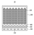
도 1은 본 발명의 일 실시예에 따른 전지 모듈의 일단면을 도시한 도면이다.1 is a view showing an end surface of a battery module according to an embodiment of the present invention.
도 1에 도시된 바와 같이, 본 발명의 일 실시예에 따른 전지 모듈(10)은, 복수의 전지셀(100), 복수의 전지셀(100)을 수용하는 하우징(200), 하우징(200)의 외측면에 배치되어 내부에 냉매(310)가 흐르는 냉각부(300)를 포함하는 전지 모듈(10)로서, 복수의 전지셀(100)의 일측에 접하도록, 하우징(200)의 내측면에 형성되는 제1 열전달부(400)를 포함하며, 하우징(200)은 복수의 전지셀(100)의 굴곡진 형태에 따라 굴곡진 부분을 가질 수 있다. 또한, 본 발명은 하우징(200)의 외측면에 접하도록, 하우징(200)의 외측면과 냉각부(300) 사이에 배치되는 제2 열전달부(500)를 더 포함할 수 있다.As shown in Figure 1, the
도 1에서는 하우징(200)의 내측면 및 외측면이 모두 굴곡진 형태이나, 이에한정되는 것은 아니다. 본 발명에서의 하우징(200)의 내측면 및 외측면 중 적어도 하나의 면은 복수의 전지셀(100)의 굴곡을 따라 굴곡진 부분을 가질 수 있으며, 이에 따라, 하우징(200)의 굴곡진 부분과 접하도록 배치된 제1 열전달부(400) 및 제2 열전달부(500) 중 적어도 하나는, 하우징(200)의 굴곡을 따라 형성될 수 있다.In FIG. 1, both the inner and outer surfaces of the
이에 대하여는 이하 도 2 내지 도 6을 통하여 자세히 설명하도록 한다.This will be described in detail with reference to FIGS. 2 to 6 below.
도 2는 비교예에 따른 전지 모듈에서 배치되는 열전달부를 설명하기 위하여 도시한 도면이며, 도 3은 본 발명의 일 실시예에 따른 전지 모듈에 있어서, 제1 열전달부를 설명하기 위하여 도시한 도면이다.2 is a view illustrating a heat transfer unit disposed in a battery module according to a comparative example, and FIG. 3 is a diagram illustrating a first heat transfer unit in a battery module according to an embodiment of the present invention.
도 2에 도시된 바와 같이, 비교예에 따른 전지 모듈에서의 하우징(200)의 내측면은 평평한 형태인 것을 확인할 수 있다. 이 경우, 복수의 전지셀(100)들의 하부면과 평평한 하우징(200) 내측면 사이에는, 도 2에 도시된 것과 같은 형태로 제1 열전달부(400)가 형성될 수 있다. 확대된 도면에서 볼 수 있듯이, 전지셀(100)에서 발생된 열이 전달되는 과정, 방향을 보면, 굴곡진 전지셀(100)의 형태, 전지셀(100)과 접촉되는 제1 열전달부(400)의 형태, 제1 열전달부(400)와 하우징(200)이 접하게 되는 부분의 형태에 따라, 전지셀(100) 내부로부터 외부를 향하여 열이 전달되는 방향, 면적이, 이하에서 설명하는 본 발명의 일 실시예에 따른 전지 모듈을 나타내는 도 3에 비하여 효율적이지 않을 수 있다.2, it can be seen that the inner surface of the
도 3은 본 발명의 제1 열전달부(400)를 설명하기 위한 것으로서, 도 2와는 달리 하우징(200)의 내측면이 전지셀(100)의 굴곡에 따라, 굴곡진 형태임을 확인할 수 있다. 이에 따라, 전지셀(100)의 일측과 하우징(200)의 내측면 사이에 형성된 제1 열전달부(400)는, 도 2에서와 달리, 전지셀(100)의 굴곡을 따라 얇게 배치된 모습을 확인할 수 있다.3 is for explaining the first
제1 열전달부(400)가 이와 같이 얇은 형태의, 굴곡을 가진 형태로 형성됨에 따라, 전지셀(100)에서 발생된 열이 제1 열전달부(400)를 통하여 하우징(200) 외부로 전달될 때, 열 저항이 낮아지게 된다. 즉, 도 2에서 설명한 전지 모듈에 비하여, 전지셀(100)로부터 제1 열전달부(400)로의 열 전달 경로가 이전에 비하여 줄어들었으며, 뿐만 아니라, 전지셀(100)의 굴곡과 같은 형상의 제1 열전달부(400)로 인하여, 열 전달 면적이 확대되는 효과도 얻을 수 있음을 확인할 수 있다.As the first
도 4는 본 발명의 다른 일 실시예에 따른 전지 모듈에 있어서, 제1 열전달부를 설명하기 위하여 도시한 도면이다.4 is a view illustrating a first heat transfer unit in a battery module according to another embodiment of the present invention.
도 4를 참고하면, 하우징(200)의 내측면만이 굴곡진 형태였던 도 3의 전지 모듈과는 달리, 도 4에서는 하우징(200)의 내측면과 외측면이 모두 전지셀(100)의 굴곡을 따라 굴곡진 형태임을 확인할 수 있다.Referring to FIG. 4, unlike the battery module of FIG. 3, in which only the inner surface of the
도 3에서는 제1 열전달부(400)에서 하우징(200)으로 전달되는 열 전달 과정에서, 열 전달 경로가 축소되고, 열 전달 면적이 확대되는 효과가 있었다면, 도 4에서는, 제1 열전달부(400)에서 하우징(200)으로 전달되는 과정뿐만 아니라, 하우징(200)에서 하우징(200) 외부로 열이 전달되는 과정에서도 열 전달 경로 축소, 열 전달 면적이 확대되는 효과가 있음에 차이가 있다. 즉, 도 4에서와 같이, 하우징(200)의 내측면, 외측면, 및 전지셀(100)의 일측과 하우징(200) 사이에 배치된 제1 열전달부(400)가 모두 전지셀(100)과 같이 굴곡진 형태인 경우, 전지셀(100)로부터 하우징(200) 외부를 향하는 열 전달 과정에서, 열 저항을 최소화시킬 수 있다.In FIG. 3, in the heat transfer process transferred from the first
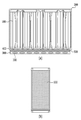
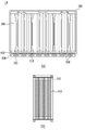
도 5는 본 발명의 일 실시예에 따른 전지 모듈에 있어서, 제2 열전달부를 설명하기 위하여 도시한 도면이고, 도 6은 본 발명의 다른 일 실시예에 따른 전지 모듈에 있어서, 제2 열전달부를 설명하기 위하여 도시한 도면이다.5 is a view illustrating a second heat transfer unit in a battery module according to an embodiment of the present invention, and FIG. 6 illustrates a second heat transfer unit in a battery module according to another embodiment of the present invention It is a drawing shown in order to.
도 5 (a)는 도 3에서와 같이, 하우징(200)의 내측면에만 굴곡이 있는 경우로서, 하우징(200)의 외측면은 평평한 형태인 일 실시예를 도시한 도면이다. 이 경우, 하우징(200)의 외측면과 냉각부(300) 사이에 배치되는 제2 열전달부(500)는 도 5(b)에 도시된 바와 같이, 평평한 평면 형태로 형성될 수 있다.FIG. 5(a) is a case in which only the inner surface of the
반면에, 도 6(a)는 다른 실시예로서, 도 4에 도시된 바와 같이, 하우징(200)의 내측면 및 외측면이 모두 전지셀(100) 일측의 굴곡진 형태에 따라 굴곡된 모양인 경우이다. 즉, 도 6에서, 하우징(200) 외측면에 형성된 굴곡에 따라, 제 2 열전달부(500)가 배치되어 있으며, 도 5에서의 평평한 평면 형태와는 상이한 모습임을 확인할 수 있다.On the other hand, Figure 6 (a) is another embodiment, as shown in Figure 4, both the inner surface and the outer surface of the
도 6에서의 하우징(200)에는, 하우징(200) 외측면의 굴곡에 의하여, 굴곡과 나란하게 홈(210)이 형성될 수 있다. 도 6(a) 에서와 같이, 제2 열전달부(500)는 이와 같이, 굴곡에 의해 형성된 홈(210) 내에 형성되는 것이며, 제2 열전달부(500)가 배치된 모습을 도시한 도 6(b)에서와 같이, 제2 열전달부(500)는 막대 형상으로서, 복수개의 제2 열전달부(500)는, 굴곡에 의하여 형성된 복수개의 홈(210) 내에, 각각 형성될 수 있으며, 복수개 형성된 제2 열전달부(500)는 서로 이격될 수 있다.In the
도 6(a)에 도시된 바와 같이, 제1 열전달부(400)와 제2 열전달부(500) 사이에는, 하우징(200)이 일정 두께를 가진 형태로 굴곡지도록 형성될 수 있으며, 이와 같이, 내측면, 외측면이 모두 굴곡 형상을 가지는 하우징(200)의 경우, 하우징(200)의 외부에 배치된 냉각부(300)에 의하여 냉각되는 면적을 확대시킬 수 있다.As shown in Figure 6 (a), between the first
즉, 상기와 같은 구조를 통하여, 전지셀(100)에서 냉각부(300) 방향으로의 열 전달 과정에서의 열 저항[K/W]을 낮추게 되어, 냉각부(300)를 통한 냉각 효율을 높이게 되는 것으로 볼 수 있는 것이다. 열 저항[K/W]은, 열 전달 경로 길이[m]와 비례하고, 열전도도[W/m/K] 및 열 전달 면적[m2]과 반비례 하는 바, 본 발명에서의 도 4 및 도 6의 구조를 통하여, 최대한으로, 열 전달 경로 길이를 낮추고, 열 전달 면적을 높여, 최종적으로는 열 저항을 최소화시키고자 함에 목적이 있다.That is, through the above structure, the heat resistance [K/W] in the heat transfer process from the
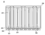
도 7은 본 발명의 또 다른 일 실시예에 따른 전지 모듈을 설명하기 위하여 도시한 도면이다.7 is a view illustrating a battery module according to another embodiment of the present invention.
도 7에 도시된 바와 같이, 도 7의 제2 열전달부(500)는, 도 5에서와 같이 평평한 형태가 아니라, 도 6에서와 같이 하우징(200) 외측에 형성된 홈(210) 내에 형성된 형태인 것을 확인할 수 있다. 다만, 도 7에 도시된 실시예와, 도 6의 차이점으로, 홈(210) 내에 형성된 제 2 열전달부(500)의 형태, 및 제2 열전달부(500)의 일측에 배치된 냉각부(300)의 형태가 상이함을 확인할 수 있다.As shown in FIG. 7, the second
우선, 도 7에 도시된 냉각부(300)는 하우징(200)의 외측면에 배치되는 것으로, 하우징(200) 외측면의 홈(210) 형태를 따라 굴곡진 형태일 수 있다. 이와 같이, 냉각부(300)가 하우징(200)의 외측면에 형성된 홈(210)에 대응되는 위치에, 하우징(200)의 홈(210) 방향으로 볼록 튀어나오는 형상을 가지게 되는 경우, 하우징(200)의 홈(210) 내에 형성된 제2 열전달부(500)의 형상은, 냉각부(300)의 배치 형태로 인하여 형상이 상이해질 수 있다. 즉, 제2 열전달부(500)는 움푹 파여지는 형상의 홈(210)과, 이에 대응되는 위치에 볼록 튀어나오는 형상의 냉각부(300) 사이의 공간에 배치되는 것으로서, 사이 공간을 따라 일정 두께를 갖도록 배치될 수가 있다.First, the
즉, 도 6에서는 홈(210)을 가득 채우도록 배치되는 형상의 제2 열전달부(500)임에 비하여, 도 7에서는 홈(210)과, 홈(210)의 굴곡을 따라 배치되는 냉각부(300) 사이의 공간만을 채우도록 배치되는 형상의 제2 열전달부(500)라는 점에서 차이가 있다. 이러한 구조상의 차이로, 도 7은, 도 6에 비하여, 제2 열전달부(500)를 최소화하는 효과가 있으며, 제2 열전달부(500)와 냉각부(300)가 접하게 되는 면적이 넓어지게 됨으로써, 냉각 면적의 확대로 냉각 효율을 높이는 효과가 있다.That is, in FIG. 6, the second
본 발명에서의 제1 열전달부(400)는 전지셀(100)을 고정시키고 열전도가 가능한 재질로서, 전도성 접착제일 수 있으며, 제2 열전달부(500)는, 방열 그리스, 전도성 접착제, 방열 패드일 수 있으나, 이에 한정되는 것은 아니다.The first
또한, 본 발명의 일 실시예에 따른 전지팩은, 복수의 전지셀(100), 복수의 전지셀(100)을 수용하는 하우징(200), 하우징(200)의 외측면에 배치된 냉각부(300)를 포함하는 전지 모듈(10)로서, 복수의 전지셀(100)의 일측에 접하도록, 하우징(200)의 내측면에 형성되는 제1 열전달부(400)를 포함하며, 하우징(200)은 복수의 전지셀(100)의 굴곡진 형태에 따라 굴곡진 부분을 갖는 전지 모듈(10)을 포함할 수 있다.In addition, the battery pack according to an embodiment of the present invention, a plurality of
위에서 설명한 바와 같이, 본 발명은 이차전지 내부와 이차전지 외부에 배치된 냉각부 간의 열 전달 과정에서, 접촉되는 부분의 열 전달 면적을 넓히고 열 전달 경로를 줄여 열 저항을 낮춤으로써, 전지 모듈의 냉각 성능을 높여, 이차 전지 내부의 열을 효율적으로 방열시킬 수 있도록 한다는 점에서 의의가 있다.As described above, according to the present invention, in the process of heat transfer between a secondary battery inside and a cooling unit disposed outside the secondary battery, the thermal resistance of the battery module is reduced by increasing a heat transfer area of a contact portion and reducing a heat transfer path. It is significant in that it improves performance and efficiently dissipates heat inside the secondary battery.
앞에서 설명한 전지 모듈은 전지팩에 포함될 수 있다. 전지팩은, 본 실시예에 따른 전지 모듈을 하나 이상 모아서 전지의 온도나 전압 등을 관리해 주는 전지 관리시스템(Battery Management System; BMS)과 냉각 장치 등을 추가하여 패킹한 구조일 수 있다.The battery module described above may be included in the battery pack. The battery pack may have a structure in which one or more battery modules according to this embodiment are collected and packed by adding a battery management system (BMS) and a cooling device to manage the temperature or voltage of the battery.
상기 전지팩은 다양한 디바이스에 적용될 수 있다. 이러한 디바이스에는, 전기 자전거, 전기 자동차, 하이브리드 자동차 등의 운송 수단에 적용될 수 있으나, 본 발명은 이에 제한되지 않고 전지 모듈을 사용할 수 있는 다양한 디바이스에 적용 가능하며, 이 또한 본 발명의 권리범위에 속한다.The battery pack can be applied to various devices. Such a device may be applied to a transportation means such as an electric bicycle, an electric vehicle, a hybrid vehicle, etc., but the present invention is not limited thereto, and can be applied to various devices that can use a battery module, which also falls within the scope of the present invention. .
이상에서 본 발명의 바람직한 실시예에 대하여 상세하게 설명하였지만 본 발명의 권리범위는 이에 한정되는 것은 아니고 다음의 청구범위에서 정의하고 있는 본 발명의 기본 개념을 이용한 당업자의 여러 변형 및 개량 형태 또한 본 발명의 권리범위에 속하는 것이다.The preferred embodiments of the present invention have been described in detail above, but the scope of the present invention is not limited thereto, and various modifications and improvements of those skilled in the art using the basic concepts of the present invention defined in the following claims are also provided. It belongs to the scope of rights.
10: 전지 모듈
100: 전지셀
200: 하우징
210: 홈
300: 냉각부
310: 냉매
400: 제1 열전달부
500: 제2 열전달부10: battery module
100: battery cell
200: housing
210: home
300: cooling unit
310: refrigerant
400: first heat transfer unit
500: second heat transfer unit
Claims (13)
상기 복수의 전지셀의 일측에 접하도록, 상기 하우징의 내측면에 형성되는 제1 열전달부를 포함하며,
상기 하우징은 상기 복수의 전지셀의 굴곡진 형태에 따라 굴곡진 부분을 갖는 전지 모듈.A battery module including a plurality of battery cells, a housing accommodating the plurality of battery cells, and a cooling unit disposed on an outer surface of the housing,
It includes a first heat transfer portion formed on the inner surface of the housing, so as to contact one side of the plurality of battery cells,
The housing is a battery module having a curved portion according to the curved shape of the plurality of battery cells.
상기 하우징의 내측면 및 외측면 중 적어도 하나가 굴곡진 부분을 갖는 전지 모듈.According to claim 1,
A battery module, wherein at least one of the inner surface and the outer surface of the housing has a curved portion.
상기 하우징의 굴곡진 부분과 접하도록 형성된 상기 제1 열전달부는, 상기 하우징의 굴곡을 따라 형성된 굴곡진 부분을 갖는 전지 모듈.According to claim 2,
The first heat transfer portion formed to contact the curved portion of the housing, the battery module having a curved portion formed along the curvature of the housing.
상기 하우징의 외측면에 접하도록, 상기 하우징의 외측면과 상기 냉각부 사이에 배치되는 제2 열전달부를 더 포함하는 전지 모듈.According to claim 1,
A battery module further comprising a second heat transfer unit disposed between the outer surface of the housing and the cooling unit to contact the outer surface of the housing.
상기 제2 열전달부는 평면 형태를 갖는 전지 모듈.According to claim 4,
The second heat transfer unit is a battery module having a flat shape.
상기 제2 열전달부는,
상기 하우징 외측면의 굴곡에 의하여, 상기 굴곡에 의해 형성된 홈 내에 형성되는 전지 모듈.According to claim 4,
The second heat transfer unit,
A battery module formed in a groove formed by the bending by bending the outer surface of the housing.
상기 제2 열전달부는 막대 형상인 전지 모듈.The method of claim 6,
The second heat transfer unit is a battery module having a rod shape.
상기 제2 열전달부는 복수개이며,
상기 굴곡으로 형성된 복수개의 홈 내에, 각각 삽입되면서 서로 이격되는 전지 모듈.According to claim 4,
A plurality of the second heat transfer portion,
A battery module spaced apart from each other while being inserted into a plurality of grooves formed by the bend.
상기 제1 열전달부와 상기 제2 열전달부 사이에는, 상기 하우징은 내측면과 외측면이 모두 굴곡지도록 형성되는 전지 모듈.According to claim 4,
Between the first heat transfer portion and the second heat transfer portion, the housing is a battery module that is formed such that both the inner and outer surfaces are curved.
상기 제1 열전달부는,
굴곡을 갖는 형태인 전지 모듈.According to claim 1,
The first heat transfer unit,
Battery module having a bent shape.
상기 제1 열전달부는 전도성 접착제인 전지 모듈.According to claim 1,
The first heat transfer unit is a battery module that is a conductive adhesive.
상기 제2 열전달부는, 방열 그리스, 전도성 접착제 및 방열 패드 중 하나인 전지 모듈.According to claim 1,
The second heat transfer unit, a battery module that is one of a heat dissipating grease, a conductive adhesive and a heat dissipation pad.
Priority Applications (6)
| Application Number | Priority Date | Filing Date | Title |
|---|---|---|---|
| KR1020190001978A KR102409856B1 (en) | 2019-01-07 | 2019-01-07 | Battery module, and battery pack including the same |
| PCT/KR2020/000207 WO2020145600A1 (en) | 2019-01-07 | 2020-01-06 | Battery module, and battery pack including same |
| CN202080002949.9A CN112204806B (en) | 2019-01-07 | 2020-01-06 | Battery module and battery pack including the battery module |
| EP20737878.7A EP3780251A4 (en) | 2019-01-07 | 2020-01-06 | BATTERY MODULE AND BATTERY PACK INCLUDING IT |
| JP2020564484A JP7214292B2 (en) | 2019-01-07 | 2020-01-06 | Battery modules and battery packs containing the same |
| US17/057,883 US11757148B2 (en) | 2019-01-07 | 2020-01-06 | Battery module, and battery pack including the same |
Applications Claiming Priority (1)
| Application Number | Priority Date | Filing Date | Title |
|---|---|---|---|
| KR1020190001978A KR102409856B1 (en) | 2019-01-07 | 2019-01-07 | Battery module, and battery pack including the same |
Publications (2)
| Publication Number | Publication Date |
|---|---|
| KR20200085616A true KR20200085616A (en) | 2020-07-15 |
| KR102409856B1 KR102409856B1 (en) | 2022-06-15 |
Family
ID=71520813
Family Applications (1)
| Application Number | Title | Priority Date | Filing Date |
|---|---|---|---|
| KR1020190001978A Active KR102409856B1 (en) | 2019-01-07 | 2019-01-07 | Battery module, and battery pack including the same |
Country Status (6)
| Country | Link |
|---|---|
| US (1) | US11757148B2 (en) |
| EP (1) | EP3780251A4 (en) |
| JP (1) | JP7214292B2 (en) |
| KR (1) | KR102409856B1 (en) |
| CN (1) | CN112204806B (en) |
| WO (1) | WO2020145600A1 (en) |
Cited By (5)
| Publication number | Priority date | Publication date | Assignee | Title |
|---|---|---|---|---|
| KR20220039584A (en) * | 2020-09-21 | 2022-03-29 | 리비안 아이피 홀딩스, 엘엘씨 | Temperature gradient control with thermal interface material variation |
| WO2022119154A1 (en) * | 2020-12-03 | 2022-06-09 | 주식회사 엘지에너지솔루션 | Battery pack and device including same |
| WO2022124660A1 (en) * | 2020-12-10 | 2022-06-16 | 주식회사 엘지에너지솔루션 | Battery module and battery pack including same |
| CN114747066A (en) * | 2020-08-24 | 2022-07-12 | 株式会社 Lg新能源 | Battery module and battery pack including the same |
| WO2025244495A1 (en) * | 2024-05-24 | 2025-11-27 | 주식회사 엘지에너지솔루션 | Battery device |
Families Citing this family (4)
| Publication number | Priority date | Publication date | Assignee | Title |
|---|---|---|---|---|
| KR20230146446A (en) * | 2022-04-12 | 2023-10-19 | 주식회사 엘지에너지솔루션 | Battery module with reinforced safety |
| JP7678215B2 (en) * | 2022-06-27 | 2025-05-15 | エルジー エナジー ソリューション リミテッド | Battery pack |
| WO2025089150A1 (en) * | 2023-10-24 | 2025-05-01 | 株式会社Gsユアサ | Power storage device |
| CN118156627A (en) * | 2024-05-10 | 2024-06-07 | 晶科储能科技有限公司 | Secondary battery, battery pack and energy storage box |
Citations (5)
| Publication number | Priority date | Publication date | Assignee | Title |
|---|---|---|---|---|
| JP2014082042A (en) * | 2012-10-15 | 2014-05-08 | Toyota Motor Corp | Power storage module and heat transfer member |
| KR20140074151A (en) * | 2012-12-07 | 2014-06-17 | 타이코에이엠피(유) | Battery module |
| JP2015056218A (en) * | 2013-09-10 | 2015-03-23 | トヨタ自動車株式会社 | Temperature control structure of power storage device |
| KR20160105358A (en) * | 2015-02-27 | 2016-09-06 | 주식회사 엘지화학 | Battery module |
| KR20170070795A (en) * | 2015-12-14 | 2017-06-22 | 주식회사 엘지화학 | Battery module, battery pack comprising the battery module and vehicle comprising the battery pack |
Family Cites Families (15)
| Publication number | Priority date | Publication date | Assignee | Title |
|---|---|---|---|---|
| JP2014093240A (en) | 2012-11-06 | 2014-05-19 | Nissan Motor Co Ltd | Battery module |
| KR102028916B1 (en) * | 2012-12-31 | 2019-10-08 | 에스케이이노베이션 주식회사 | Battery Pack for Secondary Battery |
| KR101778667B1 (en) * | 2015-03-09 | 2017-09-26 | 주식회사 엘지화학 | Battery Module Comprising Cooling plates |
| KR101865995B1 (en) * | 2015-03-27 | 2018-06-08 | 주식회사 엘지화학 | Battery module |
| ES2986381T3 (en) | 2015-06-12 | 2024-11-11 | Lg Energy Solution Ltd | Battery module |
| KR101900998B1 (en) * | 2015-06-18 | 2018-09-20 | 주식회사 엘지화학 | Lightweight cooling plate, battery module comprising the same and fabricating method thereof |
| KR101939832B1 (en) * | 2015-09-23 | 2019-01-17 | 주식회사 엘지화학 | Battery module and battery pack including the same and method for manufacturing a battery module casing |
| WO2017104878A1 (en) * | 2015-12-18 | 2017-06-22 | 주식회사 엘지화학 | Battery pack |
| KR102072765B1 (en) * | 2016-02-22 | 2020-03-02 | 주식회사 엘지화학 | Battery module, battery pack comprising the battery module and vehicle comprising the battery pack |
| KR102172515B1 (en) | 2016-03-16 | 2020-10-30 | 주식회사 엘지화학 | Battery module |
| KR102256606B1 (en) | 2016-05-31 | 2021-05-26 | 주식회사 엘지에너지솔루션 | Battery module, battery pack comprising the battery module and vehicle comprising the battery pack |
| KR102051108B1 (en) | 2016-06-13 | 2019-12-02 | 주식회사 엘지화학 | Battery module, battery pack comprising the battery module and vehicle comprising the battery pack |
| KR102120118B1 (en) | 2016-08-18 | 2020-06-08 | 주식회사 엘지화학 | Battery module |
| KR102086127B1 (en) * | 2016-10-31 | 2020-03-06 | 주식회사 엘지화학 | Battery pack for providing direct cooling means to edge side of battery |
| CN114207911B (en) | 2019-08-03 | 2024-08-27 | 三洋电机株式会社 | Power supply device, electric vehicle having the same, and power storage device |
-
2019
- 2019-01-07 KR KR1020190001978A patent/KR102409856B1/en active Active
-
2020
- 2020-01-06 US US17/057,883 patent/US11757148B2/en active Active
- 2020-01-06 WO PCT/KR2020/000207 patent/WO2020145600A1/en not_active Ceased
- 2020-01-06 CN CN202080002949.9A patent/CN112204806B/en active Active
- 2020-01-06 EP EP20737878.7A patent/EP3780251A4/en active Pending
- 2020-01-06 JP JP2020564484A patent/JP7214292B2/en active Active
Patent Citations (5)
| Publication number | Priority date | Publication date | Assignee | Title |
|---|---|---|---|---|
| JP2014082042A (en) * | 2012-10-15 | 2014-05-08 | Toyota Motor Corp | Power storage module and heat transfer member |
| KR20140074151A (en) * | 2012-12-07 | 2014-06-17 | 타이코에이엠피(유) | Battery module |
| JP2015056218A (en) * | 2013-09-10 | 2015-03-23 | トヨタ自動車株式会社 | Temperature control structure of power storage device |
| KR20160105358A (en) * | 2015-02-27 | 2016-09-06 | 주식회사 엘지화학 | Battery module |
| KR20170070795A (en) * | 2015-12-14 | 2017-06-22 | 주식회사 엘지화학 | Battery module, battery pack comprising the battery module and vehicle comprising the battery pack |
Cited By (5)
| Publication number | Priority date | Publication date | Assignee | Title |
|---|---|---|---|---|
| CN114747066A (en) * | 2020-08-24 | 2022-07-12 | 株式会社 Lg新能源 | Battery module and battery pack including the same |
| KR20220039584A (en) * | 2020-09-21 | 2022-03-29 | 리비안 아이피 홀딩스, 엘엘씨 | Temperature gradient control with thermal interface material variation |
| WO2022119154A1 (en) * | 2020-12-03 | 2022-06-09 | 주식회사 엘지에너지솔루션 | Battery pack and device including same |
| WO2022124660A1 (en) * | 2020-12-10 | 2022-06-16 | 주식회사 엘지에너지솔루션 | Battery module and battery pack including same |
| WO2025244495A1 (en) * | 2024-05-24 | 2025-11-27 | 주식회사 엘지에너지솔루션 | Battery device |
Also Published As
| Publication number | Publication date |
|---|---|
| JP7214292B2 (en) | 2023-01-30 |
| WO2020145600A1 (en) | 2020-07-16 |
| EP3780251A4 (en) | 2021-06-23 |
| EP3780251A1 (en) | 2021-02-17 |
| CN112204806B (en) | 2024-12-20 |
| JP2021524137A (en) | 2021-09-09 |
| KR102409856B1 (en) | 2022-06-15 |
| CN112204806A (en) | 2021-01-08 |
| US11757148B2 (en) | 2023-09-12 |
| US20210203020A1 (en) | 2021-07-01 |
Similar Documents
| Publication | Publication Date | Title |
|---|---|---|
| KR102409856B1 (en) | Battery module, and battery pack including the same | |
| CN102422459B (en) | Battery case including elastic pressing member and battery module including same | |
| US9196938B2 (en) | Battery module | |
| KR101675013B1 (en) | Battery pack for vehicle with improved cooling efficiency | |
| US20050026014A1 (en) | Polymer batteries having thermal exchange apparatus | |
| KR20130004141A (en) | Power supply apparatus and vehicle with the same | |
| KR20210035522A (en) | Battery module, battery rack and energy storage system comprising the battery module | |
| JP2006278330A (en) | Secondary battery module | |
| JP2023537014A (en) | Battery cut-off unit and battery pack containing same | |
| JP2014089839A (en) | Power supply device and vehicle having the same | |
| KR20150131759A (en) | Battery Module Having Thermoelectric Element | |
| KR20230096847A (en) | Battery module and battery pack and vehicle including the same | |
| CN106997976B (en) | Battery radiating fin | |
| KR20130064704A (en) | Radiant heat plate for battery cell | |
| EP3934009B1 (en) | Battery module and battery pack including same | |
| US20200161723A1 (en) | Cooling device and battery apparatus including the same | |
| EP4040575A1 (en) | Battery module and battery pack including same | |
| KR20220049870A (en) | Battery module and battery pack including the same | |
| KR102085339B1 (en) | Battery Module improved heat conductive structure | |
| KR102377870B1 (en) | Battery module and battery pack including the same and vehicle | |
| KR20220081027A (en) | Battery pack and device including the same | |
| US20230246261A1 (en) | Battery module and battery pack including the same | |
| KR20230012930A (en) | Battery module, battery pack comprising the battery module and vehicle comprising the battery pack | |
| CN115428233A (en) | Battery module and battery pack including the same | |
| KR102668492B1 (en) | Air-cooled cooling structure of supercapacitor module |
Legal Events
| Date | Code | Title | Description |
|---|---|---|---|
| PA0109 | Patent application |
Patent event code: PA01091R01D Comment text: Patent Application Patent event date: 20190107 |
|
| A201 | Request for examination | ||
| PA0201 | Request for examination |
Patent event code: PA02012R01D Patent event date: 20200709 Comment text: Request for Examination of Application Patent event code: PA02011R01I Patent event date: 20190107 Comment text: Patent Application |
|
| PG1501 | Laying open of application | ||
| N231 | Notification of change of applicant | ||
| PN2301 | Change of applicant |
Patent event date: 20210510 Comment text: Notification of Change of Applicant Patent event code: PN23011R01D |
|
| E902 | Notification of reason for refusal | ||
| PE0902 | Notice of grounds for rejection |
Comment text: Notification of reason for refusal Patent event date: 20211026 Patent event code: PE09021S01D |
|
| AMND | Amendment | ||
| E601 | Decision to refuse application | ||
| PE0601 | Decision on rejection of patent |
Patent event date: 20220412 Comment text: Decision to Refuse Application Patent event code: PE06012S01D Patent event date: 20211026 Comment text: Notification of reason for refusal Patent event code: PE06011S01I |
|
| X091 | Application refused [patent] | ||
| AMND | Amendment | ||
| PX0901 | Re-examination |
Patent event code: PX09011S01I Patent event date: 20220412 Comment text: Decision to Refuse Application Patent event code: PX09012R01I Patent event date: 20211213 Comment text: Amendment to Specification, etc. |
|
| PX0701 | Decision of registration after re-examination |
Patent event date: 20220527 Comment text: Decision to Grant Registration Patent event code: PX07013S01D Patent event date: 20220512 Comment text: Amendment to Specification, etc. Patent event code: PX07012R01I Patent event date: 20220412 Comment text: Decision to Refuse Application Patent event code: PX07011S01I Patent event date: 20211213 Comment text: Amendment to Specification, etc. Patent event code: PX07012R01I |
|
| X701 | Decision to grant (after re-examination) | ||
| GRNT | Written decision to grant | ||
| PR0701 | Registration of establishment |
Comment text: Registration of Establishment Patent event date: 20220613 Patent event code: PR07011E01D |
|
| PR1002 | Payment of registration fee |
Payment date: 20220613 End annual number: 3 Start annual number: 1 |
|
| PG1601 | Publication of registration |