KR20200088496A - 연료 분사 배열체 및 피스톤 엔진을 작동하는 방법 - Google Patents
연료 분사 배열체 및 피스톤 엔진을 작동하는 방법 Download PDFInfo
- Publication number
- KR20200088496A KR20200088496A KR1020207019669A KR20207019669A KR20200088496A KR 20200088496 A KR20200088496 A KR 20200088496A KR 1020207019669 A KR1020207019669 A KR 1020207019669A KR 20207019669 A KR20207019669 A KR 20207019669A KR 20200088496 A KR20200088496 A KR 20200088496A
- Authority
- KR
- South Korea
- Prior art keywords
- fuel injection
- nozzle
- cylinder
- fuel
- valve side
- Prior art date
- Legal status (The legal status is an assumption and is not a legal conclusion. Google has not performed a legal analysis and makes no representation as to the accuracy of the status listed.)
- Granted
Links
Images


Classifications
-
- F—MECHANICAL ENGINEERING; LIGHTING; HEATING; WEAPONS; BLASTING
- F02—COMBUSTION ENGINES; HOT-GAS OR COMBUSTION-PRODUCT ENGINE PLANTS
- F02M—SUPPLYING COMBUSTION ENGINES IN GENERAL WITH COMBUSTIBLE MIXTURES OR CONSTITUENTS THEREOF
- F02M45/00—Fuel-injection apparatus characterised by having a cyclic delivery of specific time/pressure or time/quantity relationship
- F02M45/02—Fuel-injection apparatus characterised by having a cyclic delivery of specific time/pressure or time/quantity relationship with each cyclic delivery being separated into two or more parts
- F02M45/04—Fuel-injection apparatus characterised by having a cyclic delivery of specific time/pressure or time/quantity relationship with each cyclic delivery being separated into two or more parts with a small initial part, e.g. initial part for partial load and initial and main part for full load
- F02M45/08—Injectors peculiar thereto
- F02M45/086—Having more than one injection-valve controlling discharge orifices
-
- F—MECHANICAL ENGINEERING; LIGHTING; HEATING; WEAPONS; BLASTING
- F02—COMBUSTION ENGINES; HOT-GAS OR COMBUSTION-PRODUCT ENGINE PLANTS
- F02B—INTERNAL-COMBUSTION PISTON ENGINES; COMBUSTION ENGINES IN GENERAL
- F02B23/00—Other engines characterised by special shape or construction of combustion chambers to improve operation
- F02B23/02—Other engines characterised by special shape or construction of combustion chambers to improve operation with compression ignition
- F02B23/06—Other engines characterised by special shape or construction of combustion chambers to improve operation with compression ignition the combustion space being arranged in working piston
- F02B23/0645—Details related to the fuel injector or the fuel spray
- F02B23/0663—Details related to the fuel injector or the fuel spray having multiple injectors per combustion chamber
-
- F—MECHANICAL ENGINEERING; LIGHTING; HEATING; WEAPONS; BLASTING
- F02—COMBUSTION ENGINES; HOT-GAS OR COMBUSTION-PRODUCT ENGINE PLANTS
- F02B—INTERNAL-COMBUSTION PISTON ENGINES; COMBUSTION ENGINES IN GENERAL
- F02B23/00—Other engines characterised by special shape or construction of combustion chambers to improve operation
- F02B23/08—Other engines characterised by special shape or construction of combustion chambers to improve operation with positive ignition
- F02B23/10—Other engines characterised by special shape or construction of combustion chambers to improve operation with positive ignition with separate admission of air and fuel into cylinder
-
- F—MECHANICAL ENGINEERING; LIGHTING; HEATING; WEAPONS; BLASTING
- F02—COMBUSTION ENGINES; HOT-GAS OR COMBUSTION-PRODUCT ENGINE PLANTS
- F02B—INTERNAL-COMBUSTION PISTON ENGINES; COMBUSTION ENGINES IN GENERAL
- F02B31/00—Modifying induction systems for imparting a rotation to the charge in the cylinder
- F02B31/08—Modifying induction systems for imparting a rotation to the charge in the cylinder having multiple air inlets
- F02B31/085—Modifying induction systems for imparting a rotation to the charge in the cylinder having multiple air inlets having two inlet valves
-
- F—MECHANICAL ENGINEERING; LIGHTING; HEATING; WEAPONS; BLASTING
- F02—COMBUSTION ENGINES; HOT-GAS OR COMBUSTION-PRODUCT ENGINE PLANTS
- F02D—CONTROLLING COMBUSTION ENGINES
- F02D41/00—Electrical control of supply of combustible mixture or its constituents
- F02D41/30—Controlling fuel injection
- F02D41/3094—Controlling fuel injection the fuel injection being effected by at least two different injectors, e.g. one in the intake manifold and one in the cylinder
-
- F—MECHANICAL ENGINEERING; LIGHTING; HEATING; WEAPONS; BLASTING
- F02—COMBUSTION ENGINES; HOT-GAS OR COMBUSTION-PRODUCT ENGINE PLANTS
- F02D—CONTROLLING COMBUSTION ENGINES
- F02D41/00—Electrical control of supply of combustible mixture or its constituents
- F02D41/30—Controlling fuel injection
- F02D41/38—Controlling fuel injection of the high pressure type
-
- F—MECHANICAL ENGINEERING; LIGHTING; HEATING; WEAPONS; BLASTING
- F02—COMBUSTION ENGINES; HOT-GAS OR COMBUSTION-PRODUCT ENGINE PLANTS
- F02M—SUPPLYING COMBUSTION ENGINES IN GENERAL WITH COMBUSTIBLE MIXTURES OR CONSTITUENTS THEREOF
- F02M47/00—Fuel-injection apparatus operated cyclically with fuel-injection valves actuated by fluid pressure
- F02M47/02—Fuel-injection apparatus operated cyclically with fuel-injection valves actuated by fluid pressure of accumulator-injector type, i.e. having fuel pressure of accumulator tending to open, and fuel pressure in other chamber tending to close, injection valves and having means for periodically releasing that closing pressure
- F02M47/025—Hydraulically actuated valves draining the chamber to release the closing pressure
-
- F—MECHANICAL ENGINEERING; LIGHTING; HEATING; WEAPONS; BLASTING
- F02—COMBUSTION ENGINES; HOT-GAS OR COMBUSTION-PRODUCT ENGINE PLANTS
- F02M—SUPPLYING COMBUSTION ENGINES IN GENERAL WITH COMBUSTIBLE MIXTURES OR CONSTITUENTS THEREOF
- F02M61/00—Fuel-injectors not provided for in groups F02M39/00 - F02M57/00 or F02M67/00
- F02M61/14—Arrangements of injectors with respect to engines; Mounting of injectors
-
- F—MECHANICAL ENGINEERING; LIGHTING; HEATING; WEAPONS; BLASTING
- F02—COMBUSTION ENGINES; HOT-GAS OR COMBUSTION-PRODUCT ENGINE PLANTS
- F02M—SUPPLYING COMBUSTION ENGINES IN GENERAL WITH COMBUSTIBLE MIXTURES OR CONSTITUENTS THEREOF
- F02M61/00—Fuel-injectors not provided for in groups F02M39/00 - F02M57/00 or F02M67/00
- F02M61/16—Details not provided for in, or of interest apart from, the apparatus of groups F02M61/02 - F02M61/14
- F02M61/18—Injection nozzles, e.g. having valve seats; Details of valve member seated ends, not otherwise provided for
- F02M61/1806—Injection nozzles, e.g. having valve seats; Details of valve member seated ends, not otherwise provided for characterised by the arrangement of discharge orifices, e.g. orientation or size
- F02M61/1813—Discharge orifices having different orientations with respect to valve member direction of movement, e.g. orientations being such that fuel jets emerging from discharge orifices collide with each other
-
- F—MECHANICAL ENGINEERING; LIGHTING; HEATING; WEAPONS; BLASTING
- F02—COMBUSTION ENGINES; HOT-GAS OR COMBUSTION-PRODUCT ENGINE PLANTS
- F02M—SUPPLYING COMBUSTION ENGINES IN GENERAL WITH COMBUSTIBLE MIXTURES OR CONSTITUENTS THEREOF
- F02M61/00—Fuel-injectors not provided for in groups F02M39/00 - F02M57/00 or F02M67/00
- F02M61/16—Details not provided for in, or of interest apart from, the apparatus of groups F02M61/02 - F02M61/14
- F02M61/18—Injection nozzles, e.g. having valve seats; Details of valve member seated ends, not otherwise provided for
- F02M61/1806—Injection nozzles, e.g. having valve seats; Details of valve member seated ends, not otherwise provided for characterised by the arrangement of discharge orifices, e.g. orientation or size
- F02M61/1826—Discharge orifices having different sizes
-
- F—MECHANICAL ENGINEERING; LIGHTING; HEATING; WEAPONS; BLASTING
- F02—COMBUSTION ENGINES; HOT-GAS OR COMBUSTION-PRODUCT ENGINE PLANTS
- F02D—CONTROLLING COMBUSTION ENGINES
- F02D41/00—Electrical control of supply of combustible mixture or its constituents
- F02D41/30—Controlling fuel injection
- F02D41/38—Controlling fuel injection of the high pressure type
- F02D2041/389—Controlling fuel injection of the high pressure type for injecting directly into the cylinder
-
- F—MECHANICAL ENGINEERING; LIGHTING; HEATING; WEAPONS; BLASTING
- F02—COMBUSTION ENGINES; HOT-GAS OR COMBUSTION-PRODUCT ENGINE PLANTS
- F02M—SUPPLYING COMBUSTION ENGINES IN GENERAL WITH COMBUSTIBLE MIXTURES OR CONSTITUENTS THEREOF
- F02M2200/00—Details of fuel-injection apparatus, not otherwise provided for
- F02M2200/44—Valves, e.g. injectors, with valve bodies arranged side-by-side
-
- Y—GENERAL TAGGING OF NEW TECHNOLOGICAL DEVELOPMENTS; GENERAL TAGGING OF CROSS-SECTIONAL TECHNOLOGIES SPANNING OVER SEVERAL SECTIONS OF THE IPC; TECHNICAL SUBJECTS COVERED BY FORMER USPC CROSS-REFERENCE ART COLLECTIONS [XRACs] AND DIGESTS
- Y02—TECHNOLOGIES OR APPLICATIONS FOR MITIGATION OR ADAPTATION AGAINST CLIMATE CHANGE
- Y02T—CLIMATE CHANGE MITIGATION TECHNOLOGIES RELATED TO TRANSPORTATION
- Y02T10/00—Road transport of goods or passengers
- Y02T10/10—Internal combustion engine [ICE] based vehicles
- Y02T10/12—Improving ICE efficiencies
Landscapes
- Engineering & Computer Science (AREA)
- Chemical & Material Sciences (AREA)
- Combustion & Propulsion (AREA)
- Mechanical Engineering (AREA)
- General Engineering & Computer Science (AREA)
- Physics & Mathematics (AREA)
- Fluid Mechanics (AREA)
- Fuel-Injection Apparatus (AREA)
Abstract
Description
도 2 는 도 1 의 연료 분사 유닛의 다른 단면도를 도시한다.
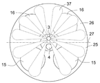
도 3 은 피스톤 엔진의 실린더와 관련된 도 1 의 연료 분사 유닛을 도시한다.
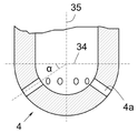
도 4 는 연료 분사기의 노즐의 간략화된 단면도를 도시한다.
도 5 는 연료 분사기의 노즐의 다른 단면도를 도시한다.
도 6 은 연료 분사기의 연료 분사 패턴의 예를 도시한다.
도 7 은 연료 분사기의 연료 분사 패턴의 다른 예를 도시한다.
Claims (25)
- 4 행정 피스톤 엔진의 실린더 (33) 를 위한 연료 분사 배열체로서,
상기 실린더 (33) 에는, 상기 실린더 (33) 의 축방향에 평행하고 상기 실린더 (33) 를 2 개의 섹션들 (25, 26) 로 분할하는 가상 평면 (27) 의 흡기 밸브측 (25) 에 배열된 2 개의 흡기 밸브들 (15), 및 상기 가상 평면 (27) 의 배기 밸브측 (26) 에 배열된 2 개의 배기 밸브들 (16) 이 제공되며,
상기 연료 분사 배열체는,
- 복수의 노즐 구멍들 (3a) 을 포함하는 제 1 연료 분사 노즐 (3),
- 복수의 노즐 구멍들 (4a) 을 포함하는 제 2 연료 분사 노즐 (4),
- 상기 제 1 연료 분사 노즐 (3) 을 통한 연료 분사를 제어하기 위한 제 1 분사기 니들 (7), 및
- 상기 제 2 연료 분사 노즐 (4) 을 통한 연료 분사를 제어하기 위한 제 2 분사기 니들 (8)
을 포함하고,
- 상기 제 2 연료 분사 노즐 (4) 의 노즐 구멍들 (4a) 의 총 단면적은 상기 제 1 연료 분사 노즐 (3) 의 노즐 구멍들 (3a) 의 총 단면적보다 크며,
- 상기 제 2 연료 분사 노즐 (4) 의 노즐 구멍들 (4a) 은, 상기 제 2 연료 분사 노즐 (4) 을 통해 분사된 연료의 더 많은 부분이 상기 실린더 (33) 의 상기 배기 밸브측 (26) 을 향하기 보다는 상기 흡기 밸브측 (25) 을 향해 분사되도록 배열되는, 연료 분사 배열체. - 제 1 항에 있어서,
상기 제 2 연료 분사 노즐 (4) 의 노즐 구멍들 (4a) 은, 상기 제 2 연료 분사 노즐 (4) 을 통해 분사된 연료의 적어도 55 % 가 상기 실린더 (33) 의 상기 흡기 밸브측 (25) 을 향해 분사되도록 구성되는, 연료 분사 배열체. - 제 2 항에 있어서,
상기 제 2 연료 분사 노즐 (4) 의 노즐 구멍들 (4a) 은, 상기 제 2 연료 분사 노즐 (4) 을 통해 분사된 연료의 적어도 60 % 가 상기 실린더 (33) 의 상기 흡기 밸브측 (25) 을 향해 분사되도록 구성되는, 연료 분사 배열체. - 제 3 항에 있어서,
상기 제 2 연료 분사 노즐 (4) 의 노즐 구멍들 (4a) 은, 상기 제 2 연료 분사 노즐 (4) 을 통해 분사된 연료의 적어도 65 % 가 상기 실린더 (33) 의 상기 흡기 밸브측 (25) 을 향해 분사되도록 구성되는, 연료 분사 배열체. - 제 1 항 내지 제 4 항 중 어느 한 항에 있어서,
상기 제 2 연료 분사 노즐 (4) 의 노즐 구멍들 (4a) 은, 상기 제 2 연료 분사 노즐 (4) 을 통해 분사된 연료의 최대 75 % 가 상기 실린더 (33) 의 상기 흡기 밸브측 (25) 을 향해 분사되도록 구성되는, 연료 분사 배열체. - 제 5 항에 있어서,
상기 제 2 연료 분사 노즐 (4) 의 노즐 구멍들 (4a) 은, 상기 제 2 연료 분사 노즐 (4) 을 통해 분사된 연료의 최대 70 % 가 상기 실린더 (33) 의 상기 흡기 밸브측 (25) 을 향해 분사되도록 구성되는, 연료 분사 배열체. - 제 1 항 내지 제 6 항 중 어느 한 항에 있어서,
상기 제 2 연료 분사 노즐 (4) 을 통해 분사된 연료의 분무 패턴은 상기 가상 평면 (27) 에 대해 비대칭인, 연료 분사 배열체. - 제 1 항 내지 제 7 항 중 어느 한 항에 있어서,
상기 제 2 연료 분사 노즐 (4) 을 통해 분사된 연료의 분무 패턴은 상기 제 2 연료 분사 노즐 (4) 의 중심 평면에 대해 비대칭이고, 상기 중심 평면은 상기 실린더 (33) 를 2 개의 섹션들 (25, 26) 로 분할하는 상기 가상 평면 (27) 에 평행한, 연료 분사 배열체. - 제 1 항 내지 제 8 항 중 어느 한 항에 있어서,
상기 제 1 연료 분사 노즐 (3) 은 상기 배기 밸브측 (26) 에 위치되고, 상기 제 2 연료 분사 노즐 (4) 은 상기 가상 평면 (27) 의 상기 흡기 밸브측 (25) 에 위치되는, 연료 분사 배열체. - 제 1 항 내지 제 9 항 중 어느 한 항에 있어서,
상기 제 2 연료 분사 노즐 (4) 의 노즐 구멍들 (4a) 의 더 많은 개수가 상기 실린더 (33) 의 상기 배기 밸브측 (26) 보다 상기 흡기 밸브측 (25) 에 대면하는, 연료 분사 배열체. - 제 1 항 내지 제 10 항 중 어느 한 항에 있어서,
상기 흡기 밸브측 (25) 에 대면하는 상기 제 2 연료 분사 노즐 (4) 의 노즐 구멍들 (4a) 각각은 상기 실린더 (33) 의 상기 배기 밸브측 (26) 에 대면하는 상기 제 2 연료 분사 노즐 (4) 의 임의의 노즐 구멍들 (4a) 보다 더 큰 단면적을 가지는, 연료 분사 배열체. - 제 1 항 내지 제 11 항 중 어느 한 항에 있어서,
상기 배기 밸브측 (26) 에 대면하는 상기 제 2 연료 분사 노즐 (4) 의 노즐 구멍들 (4a) 의 개별 단면적은 상기 실린더 (33) 의 상기 흡기 밸브측 (25) 에 대면하는 상기 제 2 연료 분사 노즐 (4) 의 노즐 구멍들 (4a) 의 개별 단면적보다 5 ~ 20 % 더 작은, 연료 분사 배열체. - 제 1 항 내지 제 12 항 중 어느 한 항에 있어서,
상기 가상 평면 (27) 은 상기 실린더 (33) 를 동일한 크기의 2 개의 하프들 (25, 26) 로 분할하는, 연료 분사 배열체. - 제 1 항 내지 제 13 항 중 어느 한 항에 있어서,
상기 실린더 (33) 의 반경 방향과 상기 실린더 (33) 의 상기 배기 밸브측 (26) 에 대면하는 상기 제 2 연료 분사 노즐 (4) 의 노즐 구멍들 (4a) 의 분사 방향 사이의 각도 (α) 는 상기 실린더 (33) 의 반경 방향과 상기 실린더 (33) 의 상기 흡기 밸브측 (25) 에 대면하는 상기 제 2 연료 분사 노즐 (4) 의 노즐 구멍들 (4a) 의 분사 방향 사이의 각도와 상이한, 연료 분사 배열체. - 제 1 항 내지 제 14 항 중 어느 한 항에 있어서,
상기 실린더 (33) 의 반경 방향과 상기 실린더 (33) 의 상기 배기 밸브측 (26) 에 대면하는 상기 제 2 연료 분사 노즐 (4) 의 노즐 구멍들 (4a) 의 분사 방향 사이의 각도 (α) 는 상기 실린더 (33) 의 반경 방향과 상기 실린더 (33) 의 상기 흡기 밸브측 (25) 에 대면하는 상기 제 2 연료 분사 노즐 (4) 의 노즐 구멍들 (4a) 의 분사 방향 사이의 각도보다 큰, 연료 분사 배열체. - 제 1 항 내지 제 15 항 중 어느 한 항에 있어서,
상기 실린더 (33) 의 반경 방향과 상기 실린더 (33) 의 상기 배기 밸브측 (26) 에 대면하는 상기 제 2 연료 분사 노즐 (4) 의 노즐 구멍들 (4a) 의 분사 방향 사이의 각도 (α) 는 상기 실린더 (33) 의 반경 방향과 상기 실린더 (33) 의 상기 흡기 밸브측 (25) 에 대면하는 상기 제 2 연료 분사 노즐 (2) 의 노즐 구멍들 (4a) 의 분사 방향 사이의 각도 (α) 보다 적어도 2 도 더 큰, 연료 분사 배열체. - 제 16 항에 있어서,
상기 배기 밸브측 (25) 및 상기 흡기 밸브측 (26) 의 분사 방향들의 각도 (α) 차이는 2 ~ 10 도인, 연료 분사 배열체. - 제 1 항 내지 제 17 항 중 어느 한 항에 있어서,
상기 제 1 연료 분사 노즐 (3) 의 노즐 구멍들 (3a) 은, 상기 제 1 연료 분사 노즐 (3) 을 통해 분사된 연료의 더 많은 부분이 상기 실린더 (33) 의 상기 흡기 밸브측 (25) 을 향하기 보다는 상기 배기 밸브측 (26) 을 향해 분사되도록 배열되는, 연료 분사 배열체. - 제 18 항에 있어서,
상기 제 1 연료 분사 노즐 (3) 의 노즐 구멍들 (3a) 은 연료의 적어도 60 % 가 상기 배기 밸브측 (26) 을 향해 분사되도록 구성되는, 연료 분사 배열체. - 제 19 항에 있어서,
상기 제 1 연료 분사 노즐 (3) 의 노즐 구멍들 (3a) 은 연료의 적어도 75 % 가 상기 배기 밸브측 (26) 을 향해 분사되도록 구성되는, 연료 분사 배열체. - 4 행정 피스톤 엔진으로서,
상기 엔진은 제 1 항 내지 제 20 항 중 어느 한 항에 따른 연료 분사 배열체를 포함하는, 4 행정 피스톤 엔진. - 제 1 항 내지 제 20 항 중 어느 한 항에 따른 연료 분사 배열체를 포함하는 피스톤 엔진을 작동하는 방법으로서,
엔진 부하가 미리 정해진 한계값 미만일 때 상기 제 1 연료 분사 노즐 (3) 만을 사용하여 상기 실린더 (33) 내로 연료가 분사되고, 상기 엔진 부하가 상기 미리 정해진 한계값을 초과할 때 적어도 제 2 연료 분사 노즐 (4) 을 사용하여 상기 실린더 (33) 내로 연료가 분사되는, 피스톤 엔진을 작동하는 방법. - 제 22 항에 있어서,
상기 엔진 부하가 상기 미리 정해진 한계값을 초과할 때 상기 제 2 연료 분사 노즐 (4) 만을 사용하여 상기 실린더 (33) 내로 연료가 분사되는, 피스톤 엔진을 작동하는 방법. - 제 22 항 또는 제 23 항에 있어서,
상기 미리 정해진 한계값은 상기 엔진의 정격 출력 동력의 30 ~ 60 % 인, 피스톤 엔진을 작동하는 방법. - 제 24 항에 있어서,
상기 미리 정해진 한계값은 상기 엔진의 정격 출력 동력의 50 ~ 60 % 인, 피스톤 엔진을 작동하는 방법.
Applications Claiming Priority (1)
| Application Number | Priority Date | Filing Date | Title |
|---|---|---|---|
| PCT/FI2018/050051 WO2019145592A1 (en) | 2018-01-23 | 2018-01-23 | Fuel injection arrangement and method of operating piston engine |
Publications (2)
| Publication Number | Publication Date |
|---|---|
| KR20200088496A true KR20200088496A (ko) | 2020-07-22 |
| KR102189095B1 KR102189095B1 (ko) | 2020-12-11 |
Family
ID=61054418
Family Applications (1)
| Application Number | Title | Priority Date | Filing Date |
|---|---|---|---|
| KR1020207019669A Active KR102189095B1 (ko) | 2018-01-23 | 2018-01-23 | 연료 분사 배열체 및 피스톤 엔진을 작동하는 방법 |
Country Status (4)
| Country | Link |
|---|---|
| EP (1) | EP3743616B1 (ko) |
| KR (1) | KR102189095B1 (ko) |
| CN (1) | CN111819356B (ko) |
| WO (1) | WO2019145592A1 (ko) |
Families Citing this family (2)
| Publication number | Priority date | Publication date | Assignee | Title |
|---|---|---|---|---|
| DE102023135721A1 (de) * | 2023-12-19 | 2025-06-26 | Man Energy Solutions Se | Kraftstoffinjektor einer Brennkraftmaschine und Brennkraftmaschine |
| JP2025097922A (ja) * | 2023-12-19 | 2025-07-01 | マン・エナジー・ソリューションズ・エスイー | 内燃機関の燃料インジェクタ及び内燃機関 |
Citations (5)
| Publication number | Priority date | Publication date | Assignee | Title |
|---|---|---|---|---|
| DE19853375A1 (de) * | 1997-11-20 | 1999-06-02 | Avl List Gmbh | Hubkolbenbrennkraftmaschine mit Fremdzündung |
| US20080210198A1 (en) * | 2006-12-22 | 2008-09-04 | Takuya Yamada | Internal combustion engine and fuel injection method in internal combustion engine |
| JP2009047073A (ja) * | 2007-08-20 | 2009-03-05 | Toyota Motor Corp | 筒内直接燃料噴射式内燃機関及び内燃機関の制御装置 |
| US20130311067A1 (en) * | 2012-05-17 | 2013-11-21 | Caterpillar Inc. | Direct Injection Gas Engine and Method |
| EP2949916A1 (en) * | 2014-05-30 | 2015-12-02 | AVL Powertrain Engineering, Inc. | Fuel injector |
Family Cites Families (15)
| Publication number | Priority date | Publication date | Assignee | Title |
|---|---|---|---|---|
| DE2121121C3 (de) * | 1971-04-29 | 1979-01-25 | Robert Bosch Gmbh, 7000 Stuttgart | Kraftstoffeinspritzdüse für Brennkraftmaschinen |
| JPH09126084A (ja) * | 1995-10-27 | 1997-05-13 | Diesel United:Kk | ディーゼル機関用燃料噴射弁 |
| JP2001280184A (ja) * | 2000-03-30 | 2001-10-10 | Hitachi Ltd | 筒内噴射式内燃機関及び筒内噴射式内燃機関における始動時の燃焼制御方法 |
| JP3518521B2 (ja) * | 2001-04-11 | 2004-04-12 | トヨタ自動車株式会社 | 内燃機関の燃料噴射制御装置 |
| JP2003193874A (ja) * | 2001-12-26 | 2003-07-09 | Nippon Ekosu Kk | ガス燃料を併用する二元燃料ディーゼルエンジン |
| JP2005307776A (ja) * | 2004-04-19 | 2005-11-04 | Toyota Motor Corp | 内燃機関 |
| JP2006037794A (ja) * | 2004-07-26 | 2006-02-09 | Nissan Motor Co Ltd | 筒内直接噴射式火花点火内燃機関 |
| CN100462534C (zh) * | 2004-10-01 | 2009-02-18 | 五十铃自动车株式会社 | 柴油机 |
| JP4906466B2 (ja) * | 2006-10-16 | 2012-03-28 | 日立オートモティブシステムズ株式会社 | 燃料噴射弁およびそれを搭載した内燃機関の燃料噴射装置 |
| FI124121B (fi) * | 2010-12-01 | 2014-03-31 | Wärtsilä Finland Oy | Polttomoottorin ohjausmenetelmä ja polttomoottori |
| DE102011118299A1 (de) * | 2011-11-10 | 2013-05-16 | Daimler Ag | Einspritzdüse |
| JP2014148947A (ja) * | 2013-02-01 | 2014-08-21 | Mazda Motor Corp | ディーゼルエンジン |
| JP6166168B2 (ja) * | 2013-12-11 | 2017-07-19 | 株式会社デンソー | 燃料噴射弁 |
| GB2523170B (en) * | 2014-02-17 | 2020-04-29 | Gm Global Tech Operations Llc | Method of operating a fuel injector |
| DE202016104439U1 (de) * | 2016-07-15 | 2016-08-18 | Ford Global Technologies, Llc | Direkteinspritzende fremdgezündete Brennkraftmaschine mit im Zylinderrohr angeordneter Einspritzvorrichtung |
-
2018
- 2018-01-23 EP EP18701780.1A patent/EP3743616B1/en active Active
- 2018-01-23 CN CN201880084902.4A patent/CN111819356B/zh active Active
- 2018-01-23 KR KR1020207019669A patent/KR102189095B1/ko active Active
- 2018-01-23 WO PCT/FI2018/050051 patent/WO2019145592A1/en not_active Ceased
Patent Citations (5)
| Publication number | Priority date | Publication date | Assignee | Title |
|---|---|---|---|---|
| DE19853375A1 (de) * | 1997-11-20 | 1999-06-02 | Avl List Gmbh | Hubkolbenbrennkraftmaschine mit Fremdzündung |
| US20080210198A1 (en) * | 2006-12-22 | 2008-09-04 | Takuya Yamada | Internal combustion engine and fuel injection method in internal combustion engine |
| JP2009047073A (ja) * | 2007-08-20 | 2009-03-05 | Toyota Motor Corp | 筒内直接燃料噴射式内燃機関及び内燃機関の制御装置 |
| US20130311067A1 (en) * | 2012-05-17 | 2013-11-21 | Caterpillar Inc. | Direct Injection Gas Engine and Method |
| EP2949916A1 (en) * | 2014-05-30 | 2015-12-02 | AVL Powertrain Engineering, Inc. | Fuel injector |
Also Published As
| Publication number | Publication date |
|---|---|
| EP3743616A1 (en) | 2020-12-02 |
| KR102189095B1 (ko) | 2020-12-11 |
| WO2019145592A1 (en) | 2019-08-01 |
| EP3743616B1 (en) | 2022-03-16 |
| CN111819356B (zh) | 2022-02-25 |
| CN111819356A (zh) | 2020-10-23 |
Similar Documents
| Publication | Publication Date | Title |
|---|---|---|
| KR102189094B1 (ko) | 연료 분사 배열체 및 피스톤 엔진을 작동하는 방법 | |
| KR101148683B1 (ko) | 디젤엔진과 가스엔진용 하이브리드형 노즐을 구비한 이중 연료분사밸브장치 | |
| US9803538B2 (en) | Ducted combustion systems utilizing duct structures | |
| US9903325B2 (en) | Dual fuel fuel-injector | |
| KR950011815A (ko) | 디젤형의 왕복동피스톤 내연기관 | |
| KR102189095B1 (ko) | 연료 분사 배열체 및 피스톤 엔진을 작동하는 방법 | |
| JP4804188B2 (ja) | インジェクタの取付構造および燃料噴射装置 | |
| US11549474B2 (en) | Ducted fuel injector having nested checks with non-rotating outer check and method of operating same | |
| JP6329999B2 (ja) | 燃料噴射ユニット及びシステム | |
| US6877477B2 (en) | Fuel injection system | |
| US9410515B2 (en) | Fuel injection apparatus for internal combustion engine | |
| WO2015199868A1 (en) | Integrated gas nozzle check valve and engine using same | |
| JP2007278220A (ja) | 内燃機関のピストン冷却構造 | |
| EP3513056B1 (en) | Fuel injector and piston bowl | |
| US10927804B2 (en) | Direct fuel injector | |
| EP3408529B1 (en) | Water injector | |
| KR101986973B1 (ko) | 이중 접촉면을 가지는 연료분사밸브 | |
| KR20250045251A (ko) | 이중 연료 인젝터 및 이를 포함하는 엔진 | |
| KR20250045252A (ko) | 이중 연료 인젝터 및 이를 포함하는 엔진 | |
| JP2021195939A (ja) | 内燃機関 |
Legal Events
| Date | Code | Title | Description |
|---|---|---|---|
| A302 | Request for accelerated examination | ||
| PA0105 | International application |
Patent event date: 20200707 Patent event code: PA01051R01D Comment text: International Patent Application |
|
| PA0201 | Request for examination | ||
| PA0302 | Request for accelerated examination |
Patent event date: 20200707 Patent event code: PA03022R01D Comment text: Request for Accelerated Examination |
|
| PG1501 | Laying open of application | ||
| E902 | Notification of reason for refusal | ||
| PE0902 | Notice of grounds for rejection |
Comment text: Notification of reason for refusal Patent event date: 20200804 Patent event code: PE09021S01D |
|
| E701 | Decision to grant or registration of patent right | ||
| PE0701 | Decision of registration |
Patent event code: PE07011S01D Comment text: Decision to Grant Registration Patent event date: 20201119 |
|
| GRNT | Written decision to grant | ||
| PR0701 | Registration of establishment |
Comment text: Registration of Establishment Patent event date: 20201203 Patent event code: PR07011E01D |
|
| PR1002 | Payment of registration fee |
Payment date: 20201203 End annual number: 3 Start annual number: 1 |
|
| PG1601 | Publication of registration |