KR20200088902A - Improved snow tire performance without dry braking or wear - Google Patents
Improved snow tire performance without dry braking or wear Download PDFInfo
- Publication number
- KR20200088902A KR20200088902A KR1020207019009A KR20207019009A KR20200088902A KR 20200088902 A KR20200088902 A KR 20200088902A KR 1020207019009 A KR1020207019009 A KR 1020207019009A KR 20207019009 A KR20207019009 A KR 20207019009A KR 20200088902 A KR20200088902 A KR 20200088902A
- Authority
- KR
- South Korea
- Prior art keywords
- tread
- transverse
- tire
- depth
- longitudinal
- Prior art date
- Legal status (The legal status is an assumption and is not a legal conclusion. Google has not performed a legal analysis and makes no representation as to the accuracy of the status listed.)
- Granted
Links
Images


Classifications
-
- B—PERFORMING OPERATIONS; TRANSPORTING
- B60—VEHICLES IN GENERAL
- B60C—VEHICLE TYRES; TYRE INFLATION; TYRE CHANGING; CONNECTING VALVES TO INFLATABLE ELASTIC BODIES IN GENERAL; DEVICES OR ARRANGEMENTS RELATED TO TYRES
- B60C11/00—Tyre tread bands; Tread patterns; Anti-skid inserts
- B60C11/03—Tread patterns
- B60C11/0327—Tread patterns characterised by special properties of the tread pattern
- B60C11/0332—Tread patterns characterised by special properties of the tread pattern by the footprint-ground contacting area of the tyre tread
-
- B—PERFORMING OPERATIONS; TRANSPORTING
- B60—VEHICLES IN GENERAL
- B60C—VEHICLE TYRES; TYRE INFLATION; TYRE CHANGING; CONNECTING VALVES TO INFLATABLE ELASTIC BODIES IN GENERAL; DEVICES OR ARRANGEMENTS RELATED TO TYRES
- B60C11/00—Tyre tread bands; Tread patterns; Anti-skid inserts
- B60C11/03—Tread patterns
- B60C11/0304—Asymmetric patterns
-
- B—PERFORMING OPERATIONS; TRANSPORTING
- B60—VEHICLES IN GENERAL
- B60C—VEHICLE TYRES; TYRE INFLATION; TYRE CHANGING; CONNECTING VALVES TO INFLATABLE ELASTIC BODIES IN GENERAL; DEVICES OR ARRANGEMENTS RELATED TO TYRES
- B60C11/00—Tyre tread bands; Tread patterns; Anti-skid inserts
- B60C11/03—Tread patterns
- B60C11/0306—Patterns comprising block rows or discontinuous ribs
-
- B—PERFORMING OPERATIONS; TRANSPORTING
- B60—VEHICLES IN GENERAL
- B60C—VEHICLE TYRES; TYRE INFLATION; TYRE CHANGING; CONNECTING VALVES TO INFLATABLE ELASTIC BODIES IN GENERAL; DEVICES OR ARRANGEMENTS RELATED TO TYRES
- B60C11/00—Tyre tread bands; Tread patterns; Anti-skid inserts
- B60C11/03—Tread patterns
- B60C11/0327—Tread patterns characterised by special properties of the tread pattern
- B60C11/033—Tread patterns characterised by special properties of the tread pattern by the void or net-to-gross ratios of the patterns
-
- B—PERFORMING OPERATIONS; TRANSPORTING
- B60—VEHICLES IN GENERAL
- B60C—VEHICLE TYRES; TYRE INFLATION; TYRE CHANGING; CONNECTING VALVES TO INFLATABLE ELASTIC BODIES IN GENERAL; DEVICES OR ARRANGEMENTS RELATED TO TYRES
- B60C11/00—Tyre tread bands; Tread patterns; Anti-skid inserts
- B60C11/03—Tread patterns
- B60C11/12—Tread patterns characterised by the use of narrow slits or incisions, e.g. sipes
- B60C11/1204—Tread patterns characterised by the use of narrow slits or incisions, e.g. sipes with special shape of the sipe
-
- B—PERFORMING OPERATIONS; TRANSPORTING
- B60—VEHICLES IN GENERAL
- B60C—VEHICLE TYRES; TYRE INFLATION; TYRE CHANGING; CONNECTING VALVES TO INFLATABLE ELASTIC BODIES IN GENERAL; DEVICES OR ARRANGEMENTS RELATED TO TYRES
- B60C11/00—Tyre tread bands; Tread patterns; Anti-skid inserts
- B60C11/03—Tread patterns
- B60C11/12—Tread patterns characterised by the use of narrow slits or incisions, e.g. sipes
- B60C11/1236—Tread patterns characterised by the use of narrow slits or incisions, e.g. sipes with special arrangements in the tread pattern
-
- B—PERFORMING OPERATIONS; TRANSPORTING
- B60—VEHICLES IN GENERAL
- B60C—VEHICLE TYRES; TYRE INFLATION; TYRE CHANGING; CONNECTING VALVES TO INFLATABLE ELASTIC BODIES IN GENERAL; DEVICES OR ARRANGEMENTS RELATED TO TYRES
- B60C11/00—Tyre tread bands; Tread patterns; Anti-skid inserts
- B60C11/03—Tread patterns
- B60C11/13—Tread patterns characterised by the groove cross-section, e.g. for buttressing or preventing stone-trapping
- B60C11/1376—Three dimensional block surfaces departing from the enveloping tread contour
- B60C11/1392—Three dimensional block surfaces departing from the enveloping tread contour with chamfered block edges
-
- B—PERFORMING OPERATIONS; TRANSPORTING
- B60—VEHICLES IN GENERAL
- B60C—VEHICLE TYRES; TYRE INFLATION; TYRE CHANGING; CONNECTING VALVES TO INFLATABLE ELASTIC BODIES IN GENERAL; DEVICES OR ARRANGEMENTS RELATED TO TYRES
- B60C9/00—Reinforcements or ply arrangement of pneumatic tyres
- B60C9/18—Structure or arrangement of belts or breakers, crown-reinforcing or cushioning layers
- B60C9/20—Structure or arrangement of belts or breakers, crown-reinforcing or cushioning layers built-up from rubberised plies each having all cords arranged substantially parallel
-
- B—PERFORMING OPERATIONS; TRANSPORTING
- B60—VEHICLES IN GENERAL
- B60C—VEHICLE TYRES; TYRE INFLATION; TYRE CHANGING; CONNECTING VALVES TO INFLATABLE ELASTIC BODIES IN GENERAL; DEVICES OR ARRANGEMENTS RELATED TO TYRES
- B60C11/00—Tyre tread bands; Tread patterns; Anti-skid inserts
- B60C11/03—Tread patterns
- B60C2011/0337—Tread patterns characterised by particular design features of the pattern
- B60C2011/0339—Grooves
- B60C2011/0341—Circumferential grooves
-
- B—PERFORMING OPERATIONS; TRANSPORTING
- B60—VEHICLES IN GENERAL
- B60C—VEHICLE TYRES; TYRE INFLATION; TYRE CHANGING; CONNECTING VALVES TO INFLATABLE ELASTIC BODIES IN GENERAL; DEVICES OR ARRANGEMENTS RELATED TO TYRES
- B60C11/00—Tyre tread bands; Tread patterns; Anti-skid inserts
- B60C11/03—Tread patterns
- B60C2011/0337—Tread patterns characterised by particular design features of the pattern
- B60C2011/0339—Grooves
- B60C2011/0358—Lateral grooves, i.e. having an angle of 45 to 90 degees to the equatorial plane
-
- B—PERFORMING OPERATIONS; TRANSPORTING
- B60—VEHICLES IN GENERAL
- B60C—VEHICLE TYRES; TYRE INFLATION; TYRE CHANGING; CONNECTING VALVES TO INFLATABLE ELASTIC BODIES IN GENERAL; DEVICES OR ARRANGEMENTS RELATED TO TYRES
- B60C11/00—Tyre tread bands; Tread patterns; Anti-skid inserts
- B60C11/03—Tread patterns
- B60C2011/0337—Tread patterns characterised by particular design features of the pattern
- B60C2011/0339—Grooves
- B60C2011/0358—Lateral grooves, i.e. having an angle of 45 to 90 degees to the equatorial plane
- B60C2011/0372—Lateral grooves, i.e. having an angle of 45 to 90 degees to the equatorial plane with particular inclination angles
-
- B—PERFORMING OPERATIONS; TRANSPORTING
- B60—VEHICLES IN GENERAL
- B60C—VEHICLE TYRES; TYRE INFLATION; TYRE CHANGING; CONNECTING VALVES TO INFLATABLE ELASTIC BODIES IN GENERAL; DEVICES OR ARRANGEMENTS RELATED TO TYRES
- B60C11/00—Tyre tread bands; Tread patterns; Anti-skid inserts
- B60C11/03—Tread patterns
- B60C2011/0337—Tread patterns characterised by particular design features of the pattern
- B60C2011/0339—Grooves
- B60C2011/0381—Blind or isolated grooves
- B60C2011/0383—Blind or isolated grooves at the centre of the tread
-
- B—PERFORMING OPERATIONS; TRANSPORTING
- B60—VEHICLES IN GENERAL
- B60C—VEHICLE TYRES; TYRE INFLATION; TYRE CHANGING; CONNECTING VALVES TO INFLATABLE ELASTIC BODIES IN GENERAL; DEVICES OR ARRANGEMENTS RELATED TO TYRES
- B60C11/00—Tyre tread bands; Tread patterns; Anti-skid inserts
- B60C11/03—Tread patterns
- B60C11/12—Tread patterns characterised by the use of narrow slits or incisions, e.g. sipes
- B60C11/1236—Tread patterns characterised by the use of narrow slits or incisions, e.g. sipes with special arrangements in the tread pattern
- B60C2011/1254—Tread patterns characterised by the use of narrow slits or incisions, e.g. sipes with special arrangements in the tread pattern with closed sipe, i.e. not extending to a groove
-
- B—PERFORMING OPERATIONS; TRANSPORTING
- B60—VEHICLES IN GENERAL
- B60C—VEHICLE TYRES; TYRE INFLATION; TYRE CHANGING; CONNECTING VALVES TO INFLATABLE ELASTIC BODIES IN GENERAL; DEVICES OR ARRANGEMENTS RELATED TO TYRES
- B60C11/00—Tyre tread bands; Tread patterns; Anti-skid inserts
- B60C11/03—Tread patterns
- B60C11/12—Tread patterns characterised by the use of narrow slits or incisions, e.g. sipes
- B60C2011/129—Sipe density, i.e. the distance between the sipes within the pattern
Landscapes
- Engineering & Computer Science (AREA)
- Mechanical Engineering (AREA)
- Tires In General (AREA)
Abstract
본 개시의 실시형태는 눈길 성능이 개선된 공기압 타이어를 포함한다. 상기 타이어는 적어도 하나의 벨트 플라이의 전폭에 걸쳐 적어도 부분적으로 연장되는 캡 플라이를 포함하고, 캡 플라이는 캡 플라이 폭의 15 mm당 210N을 초과하는 파열력을 가진다. 숄더 리브는, 우선 원주 방향으로 연장되고 스키드 깊이의 75% 이하인 깊이까지 연장되는 순응 그루브 또는 사이프를 포함한다. 횡방향 사이프 및 그루브는 15 mm미만의 평균 횡특징부 간격을 제공하도록 배치된다. 횡그루브를 위한 평균 경사각은 숄더 리브에서 6도를 초과하고 중앙 리브에서 20도를 초과한다. 비-횡방향, 종방향 사이프 에지 밀도는 21.1 마이크로미터/mm2를 초과한다. 모든 횡사이프를 위한 종, 횡방향 사이프 에지 밀도는 5.5 마이크로미터/mm2를 초과한다.Embodiments of the present disclosure include pneumatic tires with improved eye-catching performance. The tire includes a cap ply that extends at least partially over the full width of the at least one belt ply, and the cap ply has a burst force greater than 210 N per 15 mm of the cap ply width. The shoulder ribs first include a conforming groove or sipe extending in the circumferential direction and extending to a depth of 75% or less of the skid depth. The transverse sipes and grooves are arranged to provide an average transverse feature spacing of less than 15 mm. The average angle of inclination for the transverse groove exceeds 6 degrees at the shoulder rib and exceeds 20 degrees at the central rib. Non-transverse and longitudinal sipe edge densities exceed 21.1 micrometers/mm 2 . The longitudinal and transverse sipe edge density for all transverse sipes exceeds 5.5 micrometers/mm 2 .

Description
본 개시의 실시형태는 전반적으로 공기압 타이어에 관한 것이다.Embodiments of the present disclosure generally relate to pneumatic tires.
공기압 타이어의 설계 시, 각종 다양한 성능 매개변수를 획득하는 것이 바람직하다. 종종, 특정한 성능 목표를 달성하기 위해 나머지 성능 측정치가 떨어지는 경우가 있다. 특정한 경우, 향상된 눈길 및 마모 성능을 제공하는 반면, 젖은 노면 및 마른 노면에서의 접지력 저하가 요구되었다. 따라서, 젖은 노면 및 마른 노면에서의 접지력 저하 없이 향상된 눈길 성능 및 마모 성능을 제공할 필요가 있다.When designing a pneumatic tire, it is desirable to obtain various performance parameters. Often, the remaining performance metrics fall to achieve a specific performance goal. In certain cases, while providing improved snow and abrasion performance, a reduction in traction was required on wet and dry surfaces. Accordingly, there is a need to provide improved eye-catching performance and abrasion performance without sacrificing traction on wet and dry surfaces.
본 개시의 실시형태는 공기압 타이어를 포함한다. 특정한 실시형태에서, 타이어는 타이어의 회전축을 따라 축방향으로 이격되는 한 쌍의 환형 비드 영역; 타이어의 회전축을 따라 축방향으로 이격되는 한 쌍의 측벽부로서, 각각의 측벽부는 회전축과 관련하여 비드 영역쌍 중 하나의 비드 영역으로부터 반경 방향으로 바깥쪽으로 연장되는 것인, 한 쌍의 측벽부; 및 측벽부 쌍 사이에서 가로 방향으로 배치되며 타이어 둘레에서 환형으로 연장되는 크라운부를 포함한다. 크라운부는 크라운부 둘레에서 환형으로 배치되는 탄성체 재료로 구성되어 타이어가 구르기 위한 외부 지면 결합측을 형성하는 트레드를 포함하고, 트레드는 반경 방향으로 연장되는 두께 및 축방향으로 연장되는 폭을 포함하며, 타이어의 마모 부분을 형성한다. 크라운부는 하나의 배열부 내에서 이격되는 복수의 세장형 보강부를 이용하여 보강된 탄성체 재료층을 각각 형성하는 하나 이상의 벨트 플라이를 더 포함하고, 이러한 하나 이상의 벨트 플라이는 반경 내측으로 트레드 아래에 배치된다. 크라운부는 한 쌍의 숄더를 더 포함하고, 각각의 숄더는 각각의 측벽부에 인접하여 배치되는 크라운 부분을 형성한다. 크라운부는 트레드와 하나 이상의 벨트 플라이 사이에서 이러한 하나 이상의 벨트 플라이로부터 반경 외측으로 배치되는 캡 플라이를 더 포함하고, 캡 플라이는 적어도 하나의 벨트 플라이의 전폭에 걸쳐 적어도 부분적으로 연장되고 각각의 숄더 내에서 적어도 부분적으로 배치되며, 캡 플라이는 하나의 배열부 내에서 이격되는 복수의 세장형 보강부를 이용하여 보강된 탄성체 재료층을 형성하고, 캡 플라이는 캡 플라이 폭의 15 mm 당 210N을 초과하는 파열력을 가지는 것을 특징으로 한다. 트레드는 트레드 내에 깊이 방향으로 연장되는 복수의 트레드 특징부를 포함하고, 이러한 트레드 특징부는 횡사이프, 횡그루브 및 종그루브를 포함하고, 종그루브는 복수의 리브를 형성하도록 배치되고, 각각의 리브는 트레드 둘레에서 환형으로 연장되고, 인접한 리브들은 종그루브들 중 하나에 의해 분리되고, 복수의 리브는 한 쌍의 숄더 리브 및 복수의 중앙 리브를 포함하고, 각각의 숄더 리브는 숄더들 중 하나 내에서 외부 지면 결합측의 서로 반대되는 가로 방향 연장부들 중에 하나를 따라 배치되고, 복수의 중앙 리브는 숄더 리브쌍 사이에 배치된다. 복수의 트레드 특징부는 트레드 두께 내에서 실질적으로 트레드의 스키드 깊이를 한정하는 깊이까지 연장되고, 스키드 깊이는 타이어 트레드의 목표 수명 중에 마모되기 위한 트레드 두께이다. 숄더 리브들 중 하나는 그루브 또는 사이프를 포함하는 세장형 순응 특징부(elongate compliance feature)를 포함하고, 세장형 순응 특징부는 우선 타이어의 원주 방향으로 연장되고, 이러한 세장형 순응 특징부의 위치에서 트레드의 스키드 깊이의 75% 이하에 달하는 깊이까지 트레드 두께 안으로 연장된다. 외부 지면 결합측을 위해, 횡사이프 및 횡그루브는 15 mm 미만의 평균 횡특징부 간격을 제공하며 배치된다. 횡그루브를 위한 평균 경사각은 숄더 리브에서 6도를 초과하고 중앙 리브에서 20도를 초과한다. 모든 횡그루브, 종그루브 및 세장형 순응 특징부를 위한 비-횡방향, 종방향 사이프 에지 밀도는 21.1 마이크로미터/mm2를 초과한다. 모든 횡사이프를 위한 종, 횡방향 사이프 에지 밀도는 5.5 마이크로미터/mm2를 초과한다. 타이어의 다른 변형예는 이하에서 설명되는 바와 같이 다소간 특징들을 임의의 조합으로 통합하거나 이하에 설명되는 바와 같이 당해 특징들을 변경함으로써 변경될 수 있음을 이해할 것이다.Embodiments of the present disclosure include pneumatic tires. In a particular embodiment, the tire comprises a pair of annular bead regions axially spaced along the axis of rotation of the tire; A pair of sidewall portions spaced axially along the rotation axis of the tire, each sidewall portion extending radially outwardly from one bead region of the bead region pair with respect to the rotation axis; And a crown portion disposed in a horizontal direction between the pair of side wall portions and extending annularly around the tire. The crown portion comprises a tread formed of an elastic material disposed annularly around the crown portion to form an outer ground engaging side for the tire to roll, the tread includes a thickness extending in the radial direction and a width extending in the axial direction, Forms the worn part of the tire. The crown portion further comprises one or more belt plies each forming a layer of elastic material reinforced using a plurality of elongated reinforcing portions spaced within one array portion, the one or more belt plies being disposed under the tread inside the radius. . The crown portion further includes a pair of shoulders, and each shoulder forms a crown portion disposed adjacent to each side wall portion. The crown portion further comprises a cap ply disposed radially outward from this one or more belt plies between the tread and the one or more belt plies, the cap ply extending at least partially over the full width of the at least one belt ply and within each shoulder At least partially disposed, the cap ply uses a plurality of elongated reinforcements spaced within one arrangement to form a layer of reinforced elastomeric material, the cap ply having a burst force exceeding 210 N per 15 mm of the cap ply width Characterized by having. The tread includes a plurality of tread features extending in a depth direction within the tread, the tread features include transverse sipes, transverse grooves and longitudinal grooves, the longitudinal grooves arranged to form a plurality of ribs, each rib tread Circumferentially extending in the circumference, adjacent ribs are separated by one of the longitudinal grooves, the plurality of ribs comprises a pair of shoulder ribs and a plurality of central ribs, each shoulder rib being external within one of the shoulders It is disposed along one of the mutually opposite transverse extensions on the ground engaging side, and a plurality of central ribs are disposed between the pair of shoulder ribs. The plurality of tread features extend within the tread thickness to a depth that substantially defines the skid depth of the tread, and the skid depth is the tread thickness for wear during the target life of the tire tread. One of the shoulder ribs includes an elongate compliance feature comprising a groove or sipe, the elongated compliance feature first extending in the circumferential direction of the tire, and the tread at the position of the elongated compliance feature It extends into the thickness of the tread to a depth of 75% or less of the skid depth. For the outer ground mating side, the transverse sipes and transverse grooves are arranged providing an average transverse feature spacing of less than 15 mm. The average angle of inclination for the transverse groove exceeds 6 degrees at the shoulder rib and exceeds 20 degrees at the central rib. The non-transverse, longitudinal sipe edge density for all transverse, longitudinal and elongated conforming features exceeds 21.1 micrometers/mm 2 . The longitudinal and transverse sipe edge density for all transverse sipes exceeds 5.5 micrometers/mm 2 . It will be understood that other variations of the tire may be altered by incorporating more or less features in any combination, as described below, or by altering these features as described below.
이상 및 여타의 다른 목적, 특징 및 이점은 첨부 도면에 예시된 바와 같이 특정한 실시형태에 관한 이하의 상세한 설명으로부터 명확해질 것이며, 도면에서 유사한 참조번호는 특정한 실시형태의 유사한 부분을 나타낸다.The above and other other objects, features and advantages will become apparent from the following detailed description of specific embodiments, as illustrated in the accompanying drawings, and like reference numbers in the drawings indicate similar parts of the specific embodiments.
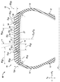
도 1은 예시적 실시형태에 따라 회전축을 관통하며 반경 방향 및 축방향으로 연장되는 평면을 따르는 타이어의 단면도이다.
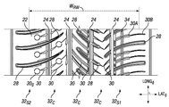
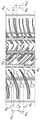
도 2는 예시적 실시형태에 따라 도 1에 도시된 타이어 트레드의 일부분을 나타내는 평면도이다.
도 3은 선행 기술의 타이어 트레드의 일부분을 나타내는 평면도이다.
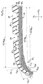
도 4는 도 1에 도시된 타이어의 단면도로, 구름폭을 어떻게 측정하는지를 나타내는 도면이다.
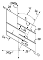
도 5a는 횡그루브들의 평균 경사각 및 횡특징부들의 간격을 어떻게 측정하는지를 나타내는 트레드 블록 평면도이다.
도 5b는 횡그루브들의 평균 경사각 및 횡특징부들의 간격을 어떻게 측정하는지를 다시 나타내는 트레드 블록 평면도이다.
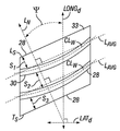
도 6은 횡사이프 에지 밀도를 결정하기 위해 사용되는 바와 같은 횡사이프들의 종방향 돌출 길이들을 예시적으로 포함하는 도 2의 트레드의 평면도이다.
도 7은 도 2의 횡사이프의 단면도이다.
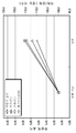
도 8은 선행 기술보다 개선된 타이어 성능 향상 측정지를 도시하는 차트 도면이다.1 is a cross-sectional view of a tire along a plane extending radially and axially through the axis of rotation in accordance with an exemplary embodiment.
Fig. 2 is a plan view showing a portion of the tire tread shown in Fig. 1 according to an exemplary embodiment.
3 is a plan view showing a portion of a prior art tire tread.
FIG. 4 is a cross-sectional view of the tire shown in FIG. 1, showing how to measure the cloud width.
5A is a tread block plan view showing how to measure the average inclination angle of transverse grooves and the spacing of transverse features.
5B is a tread block plan view showing again how to measure the average inclination angle of the transverse grooves and the spacing of the transverse features.
FIG. 6 is a top view of the tread of FIG. 2 illustratively including the longitudinal protrusion lengths of the transverse sipes as used to determine transverse edge density.
7 is a cross-sectional view of the transverse sipe of FIG. 2.
8 is a chart diagram showing improved tire performance improvement measures over prior art.
본 개시는 젖은 노면 및 마른 노면 성능을 저하시키지 않을 뿐만 아니라 오히려 개선하는 한편 향상된 눈길 및 마모 성능을 포함하는 것을 특징으로 하는 타이어를 제공하며, 이러한 타이어는 이전에 달성되지 않았던 것이었다.The present disclosure not only does not degrade wet and dry road performance, but rather provides tires characterized by including improved eye and wear performance while improving, which tires have not been previously achieved.
이제, 본 발명을 설명하기 위한 목적으로, 특정한 도면에 예시되거나 특정한 도면과 연관되는 하나 이상의 실시예를 포함하는 특정한 예시적 실시형태들이 참조될 것이다. 각각의 실시예는 본 발명의 일 예시로 제공된 것이며 본 발명을 한정하지 않는다. 실제로, 당해 기술분야의 당업자에게는 본 발명의 범위 또는 요지로부터 벗어나지 않고 본 발명에서 다양한 수정 및 변경이 이루어질 수 있음이 명확할 것이다. 예컨대, 일 실시형태의 일부로 예시되거나 설명된 특징 또는 단계는 다른 실시형태 또는 방법을 산출하기 위해 다른 실시형태의 특징 또는 단계와 함께 사용될 수 있다. 그러므로 본 발명은 그러한 수정 및 변경을 첨부된 청구범위 및 그 균등물의 범위 내에 있는 것으로서 포괄하는 것을 목적한다.For purposes of illustrating the present invention, reference will now be made to specific exemplary embodiments, including one or more embodiments illustrated in or associated with particular drawings. Each example is provided as an example of the present invention and does not limit the present invention. Indeed, it will be apparent to those skilled in the art that various modifications and changes can be made in the present invention without departing from the scope or spirit of the invention. For example, features or steps illustrated or described as part of one embodiment may be used with features or steps of other embodiments to yield other embodiments or methods. Therefore, the present invention aims to cover such modifications and variations as being within the scope of the appended claims and equivalents thereof.
이하의 용어는 본 개시를 위해 다음과 같이 한정된다:The following terms are defined as follows for this disclosure:
도면에서 "축방향" 또는 문자 "Ad"는 지표면을 따라 구를 때의 타이어 또는 타이어 카카스, 및 외부 밴드 및 내부 허브와 같은 타이어 구성요소의 회전축(A)에 대해 평행한 방향을 지칭한다. "횡방향" 또는 "가로 방향" 또는 문자 "Latd"는 축방향(Ad)의 동의어이다."Axial" or the letter "A d "in the figures refers to a direction parallel to the axis of rotation A of the tire or tire carcass, such as the outer band and inner hub, when rolling along the ground surface. . The "transverse direction" or "horizontal direction" or the letter "Lat d " is a synonym for the axial direction (A d ).
도면에서 "반경 방향" 또는 문자 "Rd"는, 축방향에 대해 직교하며 축방향으로부터 직각으로 연장되는 임의의 반경과 동일한 방향으로 연장되는 방향을 지칭한다. "반경 내측으로"는 반경 방향(Rd)에서 회전축(A)을 향하는 것을 의미한다. "반경 내측으로"는 반경 방향(Rd)에서 회전축(A)으로부터 멀어지는 것을 의미한다.In the drawings, the "radial direction" or the letter "R d "refers to a direction orthogonal to the axial direction and extending in the same direction as any radius extending at a right angle from the axial direction. "Radially inward" means towards the rotation axis A in the radial direction R d . "Inward radius" means away from the rotation axis A in the radial direction R d .
도면에서 "원주 방향" 또는 문자"Cd"는 축방향에 대해 직교하고 반경 방향에 대해서도 직교하는 방향을 지칭한다. 원주 방향은 타이어가 구르거나 회전할 때 따르는 방향이며 타이어의 회전축에 대해 수직이다. 원주 방향은 또한 종방향(Longd)으로도 지칭된다.In the drawings, "circumferential direction" or the letter "C d "refers to a direction orthogonal to the axial direction and also perpendicular to the radial direction. The circumferential direction is the direction that the tire follows when it rolls or turns and is perpendicular to the axis of rotation of the tire. The circumferential direction is also referred to as the longitudinal direction (Long d ).
"그루브(groove)"는 트레드 내에 배치되는 임의의 세장형 공극 또는 채널로서 트레드 내에서 깊이 방향으로 연장되며 서로 반대되는 한 쌍의 측벽부를 포함하고, 이러한 측벽부는 1.6 mm를 초과하여 이격되고, 다른 변형예에서 적어도 2.0 mm만큼 또는 다른 방식으로 그루브의 전체 깊이를 위해 측벽부 사이에서 측정되는 바와 같은 평균 거리만큼 이격되는데, 이러한 평균 거리는 1.6 mm를 초과하거나 2.0 mm 이상이다. 그루브는 그루브의 깊이에 기반하여 트레드가 접촉 패치에 구르며 진입, 통과 및 진출 시 개구 상태를 유지하기 위한 폭을 가지도록 설계된다. "횡그루브"는 종방향(원주 방향)에 대해 사선인 방향으로 연장되는 그루브이다. "종그루브"는 실질적으로 종방향으로 연장되는 그루브이다. "원주 그루브"는 종그루브와 동의어이며, 이들 각각은 타이어 둘레에서 환형으로 연장된다.A “groove” is any elongated void or channel disposed in a tread that extends in the depth direction within the tread and includes a pair of opposing sidewall portions that are spaced apart by more than 1.6 mm, other In a variant at least 2.0 mm apart or in another way the average distance as measured between the sidewalls for the entire depth of the groove, which average distance exceeds 1.6 mm or is more than 2.0 mm. The groove is designed so that the tread rolls into the contact patch based on the depth of the groove and has a width to maintain the opening state when entering, passing and entering. A "transverse groove" is a groove extending in a direction oblique to the longitudinal direction (circumferential direction). A "long groove" is a groove that extends substantially in the longitudinal direction. "Circumferential groove" is synonymous with longitudinal groove, each of which extends annularly around the tire.
"사이프(sipe)"는 트레드 내에 배치되는 임의의 세장형 공극 또는 절개부로서, 이러한 사이프는 트레드 내에 깊이 방향으로 연장되는 서로 반대되는 한 쌍의 측벽부를 포함하고, 이러한 측벽부들은 2.0 mm미만 또는 다른 변형예에서1.6 mm이하 또는 다른 방식으로 그루브의 총 깊이에 대하여 측벽부들 사이에서 측정되는 바와 같은 평균 거리만큼 이격되는데, 이러한 평균 거리는 2.0 mm 미만 또는 1.6 mm 이하이다. 타이어가 지면 위를 구를 때, 트레드가 타이어의 접촉 패치에 구르며 진입 및 진출함에 따라 사이프의 측벽부들은 때때로 접촉한다. 횡사이프는 종방향에 대해 사선인 방향으로 연장되는 사이프를 의미한다.A “sipe” is any elongated void or incision disposed within a tread, the sipe comprising a pair of opposing sidewalls extending in the depth direction in the tread, these sidewalls being less than 2.0 mm or In other variations, it is spaced by an average distance of less than 1.6 mm or in other ways as measured between the sidewall portions with respect to the total depth of the groove, which average distance is less than 2.0 mm or less than 1.6 mm. When the tire rolls over the ground, the side walls of the sipe sometimes make contact as the tread rolls into and out of the contact patch of the tire. The transverse sipe means a sipe extending in a direction oblique to the longitudinal direction.
"트레드 요소"는 트레드의 외부 지면 결합측을 따라 배치되는 하나 이상의 그루브 및/또는 사이프에 의해 한정되는 트레드 부분이다. 트레드 요소의 실시예는 트레드 블록 및 리브를 포함한다.A "tread element" is a tread portion defined by one or more grooves and/or sipes disposed along the outer ground engaging side of the tread. Examples of tread elements include tread blocks and ribs.
"리브"는, 실질적으로 타이어의 종방향(Ld)으로 진행하며 한 쌍의 종그루브에 의해 또는 종그루브 및 트레드의 폭을 한정하는 임의의 횡방향 측면쌍에 의해 제한되는 타이어 요소이다. 리브는 임의의 횡특징부를 포함할 수 있고, 이러한 횡특징부는 트레드 블록의 임의 배열뿐만 아니라 임의의 횡그루브 및 횡사이프를 포함한다.A "rib" is a tire element that substantially runs in the longitudinal direction (L d ) of the tire and is limited by a pair of longitudinal grooves or by any transverse side pairs defining the width of the longitudinal grooves and treads. The ribs can include any transverse features, which transverse features include any transverse grooves and transverse sipes, as well as any arrangement of tread blocks.
"트레드 블록"은 트레드의 횡방향 측면을 포함하거나 포함하지 않은 하나 이상의 그루브에 의해 한정되는 주연부를 갖는 트레드 요소로서 트레드의 고립된 구조물을 생성한다. 사이프는 트레드 블록 주연부의 임의 부분을 한정하지 않는다.A "tread block" creates an isolated structure of a tread as a tread element having a perimeter defined by one or more grooves with or without the lateral side of the tread. The sipe does not limit any part of the periphery of the tread block.
"접촉 패치"는 접촉 영역을 한정하는 주연부 내에 포함되는 전체 영역으로, 이러한 접촉 패치의 영역은 주연부 내에 포함된 접촉 영역 및 이러한 접촉 영역 내에 배치된 임의의 공극을 포함한다."Contact patch" is the entire area contained within the periphery defining the contact area, the area of this contact patch comprising the contact area contained within the periphery and any voids disposed within this contact area.
본원에 사용되는 바와 같은 "탄성 재료" 또는 "탄성체(elastomer)"는 천연 고무이든, 합성 고무이든 또는 천연 및 합성 고무들의 배합물이든 상관없이 고무를 포함하는 재료와 같이 고무와 유사한 탄성도를 보이는 중합체를 지칭한다.As used herein, "elastic material" or "elastomer" is a polymer that exhibits elasticity similar to rubber, such as a material comprising rubber, whether natural rubber, synthetic rubber, or a combination of natural and synthetic rubbers. Refers to.
본원에 사용되는 바와 같은 "탄성체의"는 고무를 포함하는 재료와 같이 탄성 재료 또는 탄성체를 포함하는 재료를 지칭한다.“Elastic” as used herein refers to an elastic material or a material comprising an elastic material, such as a material comprising rubber.
"신율(MPa)"은 아령형 시험편에 대하여 ASTM 표준 D412에 기반하여 23℃의 온도에서 10%의 변형율(MA10), 100%의 변형율(MA100) 또는 300%의 변형율(MA300)에서 측정되었다. 측정은 두 번째 연신, 즉 조절 사이클 이후에 수행되었다. 이러한 측정은 시험편의 초기 단면적에 기반하여 교차 계수[MPa]로 나타낸다."Elongation (MPa)" was measured at 10°C strain (MA10), 100% strain (MA100) or 300% strain (MA300) at a temperature of 23° C. based on ASTM standard D412 for dumbbell-shaped specimens. Measurements were taken after the second stretching, the conditioning cycle. This measurement is expressed as the crossover coefficient [MPa] based on the initial cross-sectional area of the specimen.
이력 또는 이력 손실은 P60으로 표시되고 다음의 식에 따라 60℃에서6차 반발 시 백분율 반발값으로 측정된다.Hysteresis or hysteresis loss is expressed as P60 and is measured as a percentage rebound value at the 6th repulsion at 60°C according to the following equation.
HL(%) = 100x((W0-W1)/W1),HL(%) = 100x((W0-W1)/W1),
이 식에서 W0은 공급된 에너지이고 W1은 회수된 에너지이다. P60은 시편에서 반복적으로 타격 및 반발할 수 있는 진자를 채택하는 P8을 통해 획득된다.In this equation, W0 is the supplied energy and W1 is the recovered energy. P60 is obtained through P8, which adopts a pendulum that can repeatedly strike and repel the specimen.
본원에서 사용되는 바와 같은 "탄력적"은 소기의 구동 조건 하에 소성 변형 또는 영구 변형 없이 탄성적으로 굽힘 및 가요화되도록 구성되는 것을 의미한다.“Elastic” as used herein means configured to bend and flexibly elastic without plastic deformation or permanent deformation under the desired driving conditions.
본원에 사용되는 바와 같은 "강성적"은 일반적으로 탄력적인 것과 반대되게, 소기의 구동 조건 하여 탄성적 또는 소성적으로 굽힘 또는 강제 형태 변화가 일어날 수 없는 것을 의미한다.As used herein, “rigid” means that, as opposed to generally elastic, bending or forced shape changes cannot occur elastically or plastically under the desired driving conditions.
코드(cord)는, 상기 코드가 파열력의 10%와 동일한 인장력 하에서 기껏해야 0.2%에 불과한 변형율을 보일 때 신장 가능하지 않다라고 말할 수 있다. 코드는, 상기 코드가 파열 하중과 동일한 인장력 하에서 150 GPa(기가파스칼) 미만의 최대 접선 계수를 포함하며 적어도 3%의 변형율을 보일 때 탄성적이다라고 말할 수 있다. 금속 코드 또는 실에 관한 한, "파열력"(최대 하중 [N(뉴톤)]), 파열 강도 ([MPa(메가파스칼)]) 및 파단 연신(총 연신 [%])의 측정은 23℃의 온도에서 ISO 6892 표준(1984)에 따르는 인장 하중 하에 수행되었다.It can be said that the cord is not extensible when the cord exhibits a strain of at most 0.2% under a tensile force equal to 10% of the breaking force. The cord can be said to be elastic when the cord has a maximum tangential modulus of less than 150 GPa (gigapascals) under the same tensile force as the burst load and exhibits a strain of at least 3%. As far as metal cords or yarns are concerned, measurements of "rupture force" (maximum load [N (Newton))), burst strength ([MPa (Mega Pascal)]) and elongation at break (total elongation [%]) are 23°C. It was carried out at a temperature under a tensile load according to ISO 6892 standard (1984).
도 4와 관련하여 "구름폭(rolling width)"은 트레드(20)의 외부 지면 결합측(22)의 폭을 한정하는 트레드(20)의 폭(WRW)을 지칭한다. 폭(WRW)이 도 4에 따라 한정됨으로써, 거리(WB)는 반경 최외부 벨트 플라이(402)를 따라 상기 최외부 벨트 플라이(402)의 각각의 가로 연장부에서 상기 플라이(402)의 최종 세장형 보강부(44)의 중심까지 측정된다. 이 경우, WB의 절반이 도시되어 있다. 이러한 치수의 획득 시, WB가 연장될 때 따르는 동일한 곡선 경로를 따라 WB의 각각의 가로 연장부에는 추가적인 3 mm(밀리미터)가 부가된다(총 6 mm). WB+의 각각의 가로 연장부에서 WB+가 연장될 때 따르는 곡선 경로에 대해 법선으로 연장되는 가상 선분(LN)은 지점 P22에서 외부 지면 결합측(22)과 교차한다. 트레드의 각각의 횡방향 측면에서, 횡방향(LATd)에서 측정되는 바와 같은 서로 반대되는 지점들(P22)은 트레드(20)의 구름폭(WRW) 및 외부 지면 결합측(22)을 한정하며, 도 4에서는 WRW의 절반(ㅍ)이 도시되어 있다.4, “rolling width” refers to the width W RW of the
"스키드 깊이" 또는 SD20은 트레드의 외부 지면 결합측으로부터 트레드 내에 연장되는 최심부 트레드 특징부(즉, 임의의 종- 또는 횡 그루브 또는 사이프)까지 연장되는 트레드의 두께로 한정된다. 스키드 깊이로부터 반경 내측으로 연장되는 트레드의 임의 두께는 언더트레드 두께로 지칭된다. 특정한 경우에, 도 1을 참조하면, 스키드 깊이(SD20)는 트레드에 걸쳐 횡방향으로 그리고 인접한 종그루브들(24) 사이에서 곡선 경로를 따라 연장되는데, 각각의 종그루브 저부(26)와 교차하며 최심부 횡그루브 또는 사이프의 깊이에서 각각의 숄더 리브(32S1, 32S2) 안으로 궁형의 경로를 따라 더 연장되고, 스키드 깊이(SD20)는 거리(WB)에 대하여 반경 최외부 캡 플라이(50)로부터 또는 캡 플라이가 없을 시 반경 최외부 벨트 플라이(40)로부터 실질적으로 동일한 거리로 배치될 수 있거나 배치될 수 없다. 스키드 깊이(SD20)는 타이어의 수명 중에 마모되기 위한 트레드의 유효 두께를 한정한다.The “skid depth” or SD 20 is limited to the thickness of the tread extending from the outer ground engaging side of the tread to the deepest tread feature (ie any longitudinal or transverse groove or sipe) extending in the tread. Any thickness of the tread that extends inward from the skid depth to the radius is referred to as the underthread thickness. In a particular case, referring to FIG. 1, the skid depth SD 20 extends transversely across the tread and along a curved path between adjacent
"종방향 돌출 길이"는 종그루브, 횡그루브, 횡사이프 또는 세장형 순응 특징부가 회전 방향에 대해 수직으로 돌출된 길이로서, 즉, 본래에 타이어/트레드의 종방향에서 전체적으로 연장되는 길이의 종방향 성분을 나타낸다. 예시적으로, 도 6을 참조하면, 횡사이프(30)를 위한 예시적 종방향 돌출 길이(PL (PL1 내지 PL10))가 도시되어 있는데, 각각의 종방향 돌출 길이(PL)는 횡사이프 길이의 X성분(종방향으로 연장되는 벡터 성분을 형성함)을 형성하고, 이러한 종방향 돌출 길이는 종방향(Longd)으로 연장되며, 횡사이프 길이는 별도로 종방향(Longd) 및 횡방향(Latd)으로 연장되는 벡터들로 분리된다. 도 6이 사이프(30)를 위한 종방향 돌출 길이를 도시하긴 하나, 종그루브(24), 횡그루브(28) 및 세장형 순응 특징부(34) 각각을 위한 종방향 돌출 길이도 동일한 방식으로 결정된다. 종그루브(28) 및 세장형 순응 특징부(34)에 대해, 도 2에 도시 및 설명되는 실시형태에서 이들 각각이 환형으로 연장되므로, 이들 각각을 위한 종방향 돌출 길이는 타이어 둘레에서 완전한 환형 거리로 연장된다는 것을 언급해 둔다. 각각의 종방향 돌출 길이는 각각의 대응 그루브 또는 사이프의 가로 중심선 길이에 기반하여 또는 그 대신 각각의 그루브 또는 사이프의 폭을 형성하는 임의의 측면을 따라 연장되는 임의의 에지에 기반할 수 있음을 이해할 것이다.“Longitudinal protrusion length” is the length of a longitudinal groove, transverse groove, transverse sipe or elongated conforming feature protruding perpendicular to the direction of rotation, ie, the longitudinal direction of the length extending entirely from the longitudinal direction of the tire/tread originally Ingredients. Illustratively, referring to FIG. 6, an exemplary longitudinal protrusion length PL (PL 1 to PL 10 ) for the
"비-횡방향, 종방향 사이프 에지 밀도"는 본원에 설명된 바와 같은 모든 종그루브, 횡그루브 및 세장형 순응 그루브 및 사이프의 모든 돌출된 종방향 길이를 구름폭으로 한정되는 바와 같은 트레드의 전체 표면 영역으로 나눈 것의 합이고, 이러한 길이는 실질적으로 타이어의 종방향으로 연장된다.“Non-transverse, longitudinal sipe edge density” is the total length of the tread as defined by the cloud width of all longitudinal, transverse and elongated conforming grooves and all protruding longitudinal lengths of the sipes as described herein. It is the sum of those divided by the surface area, and this length extends substantially in the longitudinal direction of the tire.
"종, 횡 방향 사이프 에지 밀도"는 타이어의 횡사이프의 모든 돌출된 종방향 길이를 구름폭으로 한정되는 바와 같은 트레드의 전체 표면 영역으로 나눈 것의 합이다.“Longitudinal, transverse sipe edge density” is the sum of all projected longitudinal lengths of the transverse sipe of a tire divided by the total surface area of the tread as defined by the cloud width.
"종방향 접촉 표면비"(종 CSR)는 종그루브들의 접촉 표면비이다. 이는, 타이어 트레드의 외부 지면 결합측을 따라 위치될 때 접촉 패치 내에 포함되는 전체 영역(Ac)으로부터 종그루브의 전체 돌출 공극 영역(Along)을 감산한 것을, 종그루브(Along)의 전체 돌출 공극 영역(Ac)을 포함하는 접촉 패치의 전체 영역으로 나눈 것이며, 이러한 공극 영역은 횡방향으로 외부 지면 결합측의 구름폭을 따라 그리고 타이어 둘레에 환형으로 연장된다. 두 영역은 mm2으로 측정된다. 이러한 연관성은 다음 식과 관련하여 표현될 수 있다: 종 CSR= (Ac - Along)/Ac, 이 식은 무차원수를 산출한다.The "longitudinal contact surface ratio" (longitudinal CSR) is the contact surface ratio of the longitudinal grooves. This is the total protruding void area A long of the longitudinal groove subtracted from the entire area A c included in the contact patch when positioned along the outer ground engaging side of the tire tread, the entirety of the longitudinal groove A long . It is divided by the entire area of the contact patch including the protruding void area (A c ), and this void area extends transversely along the rolling width of the outer ground engaging side and annularly around the tire. Both areas are measured in mm 2 . This association can be expressed in relation to the following equation: Species CSR= (A c -A long )/A c , which yields a dimensionless number.
고무 조성물에 관한 "최대 탄젠트 델타" 동적 물성은 ASTM D5992-96에 따라 Metravib 사의 점도분석기 시험 시스템 VA400 모델을 이용하여 23℃에서 측정되었다. 가황화된 재료의 시편(각각 2 mm의 두께 및 10 mm의 직경을 가지며 이중 전단 기하학적 형상을 갖는 2개의 원통형 시편)의 반응에 대하여, 이 시편이 23℃라는 제어된 온도 및 10 Hz의 주파수에서 교번적 단일 사인곡선형 전단 응력을 받았던 것으로 기록되었다. 스캐닝 효과는 0.05 내지 50%(외향 사이클)의 변형 진폭에서 나타났고, 이후에 50% 내지 0.05%(귀환 사이클)의 변형 진폭에서 나타났다. 손실 각도 탄젠트 델타의 최대 탄젠트값(max tan δ)은 귀환 사이클 중에 결정되었다.The “maximum tangent delta” dynamic properties of the rubber composition were measured at 23° C. using a Metravib viscometer test system VA400 model according to ASTM D5992-96. For the reaction of specimens of vulcanized material (two cylindrical specimens each having a thickness of 2 mm and a diameter of 10 mm and having a double shear geometry), the specimens were at a controlled temperature of 23° C. and a frequency of 10 Hz. It was recorded that it was subjected to alternating single sinusoidal shear stress. The scanning effect was seen at a strain amplitude of 0.05 to 50% (outward cycle), then at a strain amplitude of 50% to 0.05% (return cycle). The maximum tangent value (max tan δ) of the loss angle tangent delta was determined during the return cycle.
고무 조성물에 관한 동적 물성 "Tg" 및 "G*"는 ASTM D5992-96에 따라 Metravib 사의 점도분석기 시험 시스템 VA400 모델을 이용하여 측정되었다. 가황화된 재료 시편(각각 2 mm의 두께 및 10 mm의 직경을 가지며 이중 전단 기하학적 형상을 갖는 2개의 원통형 시편)의 반응에 대하여, 이 시편이 - 60℃ 부터 100℃까지 1.5℃/min의 율로 온도가 증가하는 온도 스윕 중에 10 Hz의 주파수에서 일정한 0.7 MPa의 교번적 단일 사인곡선형 전단 응력을 받았던 것으로 기록되었다. 60℃에서 동적 전단 계수(G*)가 수집되었고, 최대 탄젠트 델타가 발생한 온도는 유리 전이 온도(Tg)로 기록되었다.The dynamic properties “Tg” and “G*” for the rubber composition were measured using the Metravib viscometer test system VA400 model according to ASTM D5992-96. For the reaction of vulcanized material specimens (two cylindrical specimens each having a thickness of 2 mm and a diameter of 10 mm and having a double shear geometry), the specimens were tested at a rate of 1.5°C/min from -60°C to 100°C. It was recorded that the temperature was subjected to an alternating single sinusoidal shear stress of 0.7 MPa constant at a frequency of 10 Hz during the temperature sweep. Dynamic shear modulus (G*) was collected at 60° C., and the temperature at which the maximum tangent delta occurred was recorded as the glass transition temperature (Tg).
ASTM D1646 (1999) 표준에 기술된 바와 같은 진동 점도계가 사용되었다. "무니 가소성" 또는 "무니 점도" 측정은 다음의 원칙에 따라 수행되었다: 미경화 상태(즉, 경화 전)에서 분석된 시편은 주어진 온도(예: 100℃)로 가열된 원통형 챔버에서 모델링되었다. 1분간 예열 후, 시험편 내에서 로터가 2 rpm으로 회전하고, 이러한 운동성을 유지하기 위한 작업 토크는 4분간의 회전 이후에 측정되었다. 무니 점도(ML 1+4)는 "무니 단위"로 표현된다(MU, 1MU=0.83 newton-meter N-m). 보다 양호한 판독성을 위해, 결과물은 기초값을 100으로 하여 나타낼 것이고, 100이란 값은 제어부에 할당된다. 100 미만의 결과값은 관련값의 감소를 나타낼 것이며, 반대로, 100 초과의 결과값은 관련값의 증가를 나타낼 것이다.A vibratory viscometer as described in ASTM D1646 (1999) standard was used. Measurements of “Mooney plasticity” or “Mooney viscosity” were performed according to the following principles: Specimens analyzed in an uncured state (ie before curing) were modeled in a cylindrical chamber heated to a given temperature (eg 100° C.). After preheating for 1 minute, the rotor rotated at 2 rpm in the test piece, and the working torque for maintaining this mobility was measured after 4 minutes of rotation. Mooney viscosity (
"선회 강성"을 측정하기 위해, 각각의 타이어는1도의 드리프트 각도에서 수직 또는 반경 하중인 하중("Z"로 표시됨)을 변화시킴으로써 적합한 자동 장치(MTS사에서 공급하는 "평지 트랙" 롤링 로드 유형의 장치)에서 80 km/h의 일정 속도로 주행되고, 드리프트 추력은 휠에 가해지는 가로 하중을 "Z" 하중의 함수로서 기록하는 센서를 이용하여 측정됨으로써, 연속적으로 드리프트 추력 또는 선회 강성("D"로 표시됨)이 식별되었는데(0의 드리프트 각도에서 드리프트 추력을 위해 보정됨), 이러한 함수는 드리프트 추력 또는 선회 강성을 제공한다.To measure "slewing stiffness", each tire is fitted with a suitable automatic device ("flat track" rolling rod type supplied by MTS) by varying the load (denoted by "Z"), which is a vertical or radial load at a 1 degree drift angle. The device is driven at a constant speed of 80 km/h, and the drift thrust is measured using a sensor that records the lateral load applied to the wheel as a function of the "Z" load, thereby continuously drifting thrust or turning stiffness (" D") (corrected for drift thrust at a drift angle of 0), this function provides drift thrust or turning stiffness.
도 1을 참조하면, 공기압 타이어(10)는 일반적으로 타이어(10)의 회전축(A)을 따라 축방향에서(즉, 축방향(Ad)으로) 이격된 한 쌍의 환형 비드 영역(12), 타이어(10)의 회전축(A)을 따라 축방향에서 이격된 한 쌍의 측벽부(14), 및 이러한 측벽부쌍(14) 사이에서 가로로 배치되며 타이어(10) 둘레에 환형으로 연장되는 크라운부(16)를 포함하는 것으로 도시되어 있다. 각각의 측벽부(14)는 회전축(A)과 관련하여 비드 영역쌍(12)의 하나의 비드 영역(12)으로부터 반경 방향(Rd)으로 바깥쪽으로 연장된다. 측벽부쌍(14) 사이에 가로로 연장되는 중에, 측벽부들 사이에 연장되는 크라운부(16)의 폭(W16)이 제공된다. 트레드(20)의 구름폭(WRW) 및 외부 지면 결합측(22)도 또한 도시되어 있다. 전반적으로 18로 표시되는 숄더 영역은 숄더 리브(32S1, 32S2)를 포함한다.Referring to FIG. 1, the
계속하여 도 1을 참조하면, 크라운부(16)는, 크라운부(16) 둘레에 환형으로 배치되고 타이어(10)가 구르기 위한 외부 지면 결합측(22)을 형성하는 트레드(20)를 포함한다. 트레드(20)는 외부 지면 결합측(22)에 대해 수직인 방향 및 타이어의 회전축(A)을 향하는 방향으로 연장되는 두께(t20)를 포함한다. 트레드 두께(t20)는 외부 지면 결합측(22)으로부터 트레드의 스키드 깊이(SD20)까지 연장되고, 스키드 깊이는 타이어의 수명 중에 마모되기 위한 트레드의 두께(즉, 타이어 트레드의 마모 깊이 또는 두께)를 한정한다. 스키드 깊이(SD20)는 최심부 종그루브(24)의 저부(26)에 대응하는 깊이로 배치되는 것이 통상적이나 반드시 그래야 하는 것은 아니다. 도시된 바와 같은 경우에서, 모든 원주(종) 그루브(24)의 저부(26)는 스키드 깊이(SD20)에 배치되는 것이 통상적이나 반드시 그래야 하는 것은 아니다. 그러한 경우, 각각의 원주(종) 그루브 깊이(D24)는 동일한 깊이(D24)로 구성되거나 구성되지 않을 수 있으나, 도시된 예시적 실시형태에서 모든 원주 그루브(24)는 동일한 깊이(D24)를 포함하고 스키드 깊이(SD20)까지 연장되어 이 위치에서 종결된다. 특정한 경우에, 모든 원주 그루브(24)를 위한 평균 깊이(D24)는 8.5 mm이다. 이러한 평균은 타이어(10)의 전체 원주에 관하여 계산되었다. 특정한 경우에, 스키드 깊이(SD20)는 트레드(10)의 가로 (축방향) 중심선(CLA)에서 측정되고, 중심선(CLA)은 적도 평면(PCL)을 따라 연장되며, 이러한 위치에서 스키드 깊이(SD20)는 8.5 mm이긴 하나, 트레드의 폭에 걸쳐 동일하게 유지되거나 변경될 수 있다. 예컨대, 도 1에서 스키드 깊이(SD20)는 각각의 숄더(18)에 도달할 때까지 전반적으로 일정하게 유지되는 반면, 도 4에서 스키드 깊이(SD20)는 트레드가 트레드의 폭을 따라 횡방향으로 연장될 때 점차 감소한다. 전반적으로 도시된 바와 같이, 트레드 두께(t20)는 스키드 깊이(SD20)를 초과한 깊이까지 반경 내측으로 더 깊게 연장될 수 있다.With continued reference to FIG. 1, the
본원에서 고려되는 임의의 실시형태에서, 트레드(20)는 임의의 천연 또는 합성 고무 또는 이들의 임의 배합물과 같은 탄성체 재료로 구성된다. 특정한 경우, 트레드는 향상된 견인(접지)을 제공하기 위해 탄성체 재료로 실질적으로 형성되고, 이러한 탄성체 재료는 -25℃ 내지 -10℃의 유리 전이 온도(Tg), 0.4 내지 0.6의 최대 탄젠트 델타, 1.0 내지 1.4 MPa의 동적 전단 계수(G*), 80 내지 120의 무니 점도 및 5.75 내지 9.5의 신율(MA10)을 포함하는 것을 특징으로 한다. 이와 같이 특징지어지는 탄성체 재료는 임의의 다양한 제형을 사용하여 형성될 수 있다. 특정한 경우에, 이와 같이 특징지어지는 탄성체 재료는 탄성체, 충전제 및 가소제를 포함하는 혼합물이다. 이러한 제형에서, 탄성체는 적어도 70% 의SBR을 포함하는 SBR/BR 배합물 내지 100% SBR이거나 다른 변형예에서 SBR/BR이 70/30 또는 85/15 비율로 각각 배합된 배합물이다. "SBR"은 스티렌 부타디엔 고무이고, "BR"은 부타디엔 고무이다. SBR은 작용화된 탄성체이다. 이러한 생성물에서 충전제는 실리카 및 카본블랙을 포함하는데, 전체 탄성체 재료 혼합물에서 실리카는 23.5% 내지 25.9%, 카본 블랙은 1%를 형성한다. 이러한 생성물에서 가소제는 전체 탄성체 재료 혼합물의 25% 내지 30%를 형성하고, 전체 탄성체 재료 혼합물의 12% 내지 23%를 형성하는 고 Tg 수지 및 가소제의 평형을 형성하는 고올레산 해바라기유(2% 내지 18%)를 포함한다. 바람직한 특성 및 물성을 획득하기 위해 다른 생성물도 채택될 수 있음을 이해할 것이다.In any of the embodiments contemplated herein, the
탄성체는 본원에 개시되는 트레드(20)를 위한 탄성체 재료 조성물을 형성하기에 유용하고, 특히 개질제 및/또는 랜덤화제의 유무 및 개질제 및/또는 랜덤화제의 사용되는 양과 같이 사용되는 중합 조건의 함수인 미세 구조와 같은 임의 미세 구조를 포함할 수 있다. 탄성체는 예컨대 블록, 랜덤, 순차 또는 미세 순차 탄성체일 수 있고, 분산제 또는 용액으로 조제될 수 있다; 탄성체는 결합제 및/또는 성상화제(starring agent) 또는 작용화제와 결합 및/또는 성상화되고 또는 대안적으로 작용화될 수 있다.The elastomer is useful for forming the elastomeric material composition for the
작용화된 고무, 즉 활성 모이어티가 첨가된 고무는 해당 산업에서 잘 알려져 있다. 탄성체의 골격 또는 가지 말단은 중합체의 골격 또는 중앙 쇄에 또는 쇄 말단에 활성 모이어티를 부착함으로써 작용화될 수 있다. 디엔 탄성체에 포함될 수 있는 예시적 작용화제는 당해 기술분야에 잘 알려진 금속 할로겐화물, 준금속 할로겐화물, 알콕시실란, 이민 함유 화합물, 에스테르, 에스테르카복실레이트 금속착화물, 알킬 에스테르 카복실레이트 금속착화물, 알데히드 또는 케톤, 아미드, 이소시아네이트, 이소티오시아네이트 및 이민을 포함하나 이에 한정되지 않는다. 특정한 실시형태는 작용화된 디엔 탄성체를 포함할 수 있으나, 다른 실시형태는 작용화된 디엔 탄성체를 포함하지 않는 것에 한정될 수 있다.Functionalized rubbers, ie rubbers with active moieties, are well known in the art. The backbone or branch end of the elastomer can be functionalized by attaching an active moiety to the backbone or central chain of the polymer or to the chain end. Exemplary functionalizing agents that may be included in the diene elastomer include metal halides, metalloid halides, alkoxysilanes, imine-containing compounds, esters, ester carboxylate metal complexes, alkyl ester carboxylate metal complexes well known in the art, Aldehydes or ketones, amides, isocyanates, isothiocyanates and imines. Certain embodiments may include functionalized diene elastomers, while other embodiments may be limited to non-functionalized diene elastomers.
특정한 실시형태는 작용화된 탄성체의 적어도 80 phr을 포함하거나 대안적으로 작용화된 탄성체의 적어도 90 phr 또는 100 phr을 포함하고, 작용 모이어티는 실리카 충전제와 상호작용한다. 당해 기술분야에 공지된 예시는 실란올 작용기 또는 실란올 말단을 갖는 폴리실록산 작용기(예컨대 FR 2 740 778 또는 US 6,013,718에 기술된 바와 같음), 알콕시실란기(예컨대 FR 2 765 882 또는 US 5,977,238에 기술된 바와 같음), 카복실기(예컨대 WO 01/92402 또는 US 6,815,473, WO 2004/096865 또는 US 2006/0089445에 기술된 바와 같음) 또는 여타 폴리에테르기(예컨대 EP 1 127 909 또는 US 6,503,973에 기술된 바와 같음)를 포함하고, 언급된 문헌들 각각은 본원에 참조로 통합된다.Certain embodiments include at least 80 phr of functionalized elastomer or alternatively at least 90 phr or 100 phr of functionalized elastomer, and the functional moiety interacts with the silica filler. Examples known in the art include silanol functional groups or polysiloxane functional groups having silanol ends (such as described in FR 2 740 778 or US 6,013,718), alkoxysilane groups (such as described in FR 2 765 882 or US 5,977,238) As described), carboxyl groups (such as described in WO 01/92402 or US 6,815,473, WO 2004/096865 or US 2006/0089445) or other polyether groups (such as described in
본원에 개시되는 고무 조성물에 관한 특정한 실시형태는 고 불포화 디엔 탄성체인 고무 성분의 적어도 80 phr을 갖는 조성물에 한정된다. 다른 실시형태는 고 불포화 디엔 탄성체 성분의 적어도 90 phr 또는 100 phr을 포함하는 것에 한정된다.Certain embodiments relating to the rubber composition disclosed herein are limited to compositions having at least 80 phr of a rubber component that is a highly unsaturated diene elastomer. Other embodiments are limited to including at least 90 phr or 100 phr of the highly unsaturated diene elastomer component.
적합한 고 불포화 디엔 탄성체의 예시는 천연 고무(NR), 폴리부타디엔(BR), 폴리이소프렌(IR), 부타디엔 공중합체, 이소프렌 공중합체 및 이러한 탄성체의 혼합물과 같은 합성 고무를 포함하나 반드시 이에 한정되지 않는다. 그러한 공중합체는 부타디엔/스티렌 공중합체(SBR), 이소프렌/부타디엔 공중합체(BIR), 이소프렌/스티렌 공중합체(SIR) 및 이소프렌/부타디엔/스티렌 삼원공중합체(SBIR)를 포함한다. 이러한 예시 또는 이러한 예시의 혼합물 중 임의의 것은 본원에 개시되는 고무 조성물의 특정한 실시형태를 위해 적합하다.Examples of suitable highly unsaturated diene elastomers include, but are not limited to, natural rubber (NR), polybutadiene (BR), polyisoprene (IR), butadiene copolymers, isoprene copolymers, and synthetic rubbers such as mixtures of these elastomers. . Such copolymers include butadiene/styrene copolymer (SBR), isoprene/butadiene copolymer (BIR), isoprene/styrene copolymer (SIR) and isoprene/butadiene/styrene terpolymer (SBIR). Any of these examples or mixtures of these examples are suitable for particular embodiments of the rubber compositions disclosed herein.
특정한 실시형태에서, 유용한 SBR 탄성체는 1 mol%와 45 mol% 사이 또는 대안적으로 15 mol%와 40 mol% 사이 또는 20 mol%와 30 mol%사이의 함량으로 결합 스티렌을 포함할 수 있다. 본원에 개시되는 고무 조성물의 특정한 실시형태는 실리카 충전제와 상호작용하는 모이어티를 이용하여 작용화되는 SBR을 포함한다.In certain embodiments, useful SBR elastomers can include binding styrene in an amount between 1 mol% and 45 mol% or alternatively between 15 mol% and 40 mol% or between 20 mol% and 30 mol%. Certain embodiments of the rubber compositions disclosed herein include SBR functionalized with a moiety that interacts with a silica filler.
도 4를 참조하면, 크라운부(16)는 하나 이상의 벨트 플라이(40)를 포함하고(전반적으로 그러하고, 더욱 상세하게는 제1 및 제2 벨트 플라이(401, 402)를 포함함), 이러한 벨트 플라이 각각은 하나의 배열부 내에서 이격되는 복수의 세장형 보강부(44)를 이용하여 보강되는 탄성체 재료층(42)을 형성하고, 하나 이상의 벨트 플라이는 트레드 아래에서 반경 내측으로 배치된다. 하나 이상의 벨트 플라이는 함께 "벨트"를 형성하고, 이러한 벨트는 또한 "벨트 구조물"로도 지칭되며 하나 이상의 벨트 플라이(40)에 의해 형성되는 환형 구조물을 형성한다. 각각의 세장형 보강부(44)는 금속 또는 비금속 세장형 보강부로 형성될 수 있고, 바람직하게는 세장형 보강부(44)는 길이 방향으로 배치되고 그 길이를 따라 꼬임이 있는 복수의 필라멘트로 형성된다. 금속 세장형 보강부는 가장 통상적으로는 강으로 형성되는 필라멘트로 구성되나 원하는 물성을 갖는 임의의 금속으로 형성될 수 있다. 비금속 보강부는 폴리에스테르, 레이온, 나일론, 아라미드, 실크 및/또는 유리섬유와 같은 임의의 섬유 또는 직물로 형성되는 필라멘트로 구성된다. 도시된 예시적 실시형태에서, 타이어(10)는 환형 벨트 구조물을 형성하는 한 쌍의 벨트 플라이(40)를 포함하나, 임의의 하나 이상의 벨트 플라이(40)에 의해 형성되는 환형 벨트 구조물의 바람직한 물성을 획득하기 위해 임의의 단일 벨트 플라이(40) 또는 3개 이상의 벨트 플라이(40)가 채택될 수 있다.Referring to FIG. 4, the
특정한 실시형태에서, 각각의 세장형 보강부(44)는 420N 내지 520N에 달하는 파열력을 가지는 것을 특징으로 한다. 세장형 보강부(44)는 종방향(Longd)과 관련하여 길이 방향으로 24도 초과 및 최대 32도까지 연장되며 배치되고, 다른 경우에 종방향(Longd)과 관련하여 26도 내지 30도 또는 실질적으로 28도로 연장되며 배치된다. 예컨대, 이러한 특징은 각각의 세장형 보강부(44)가 0.60 mm 두께의 강 케이블을 이루도록 형성됨으로써 달성될 수 있다. 케이블은 0.3 mm 직경을 갖는 두(2) 개의 꼬인 강 필라멘트로 형성된다. 이러한 세장형 보강부(44) 각각은 470N의 파열력을 가지는 것을 특징으로 한다. 하나 이상의 벨트 플라이(40) 각각에서 복수의 세장형 보강부(44)는 하나 이상의 벨트 플라이 각각의 탄성체 재료(42)와 함께 중심선 대 중심선이 실질적으로 1 mm 만큼 이격되는데, 이는 세장형 보강부(44)의 페이스를 한정한다. 탄성체 재료(42)는 1.08 mm의 두께를 가지고, P8 진자 시험 수행 결과로서 측정된 바와 같이 신율이 10.5 미만이고, 60도에서 이력(P60)으로 인한 손실이26.5 미만인 것을 특징으로 한다. 이격된 세장형 보강부(44) 사이에 정착되는 탄성체 재료(42)와 함께, 타이어에 적용되기 전 미경화 상태의 각각의 벨트 플라이(40)는 1.22 mm의 두께를 가진다(선행 고성능 승용차용 타이어에 사용되는 벨트 플라이의 두께는 1.42 mm이었음). 요약하자면, 각각의 벨트 플라이(40)의 질량은 관련된 승용차용 (고성능) 타이어에서 이전에 사용된 벨트 플라이에 비해 5.5% 감소되었다(2.531 kg/mm2에서 2.394 kg/mm2로 감소). 페이스를 줄이면 보다 많은 보강부(44)를 임의의 주어진 크기의 벨트 플라이(40) 내에 포함시킬 수 있긴 하나, 부가적인 세장형 보강부는 세장형 보강부의 직경 감소에 따라 수득되는 질량 감소를 상쇄시키지 않는다(또한, 부가적인 세장형 보강부는 탄성 재료(42)의 감소도 허용함). 전술한 바와 같이, 이력이 감소된 탄성체 재료(42)가 채택될 수 있고, 이러한 탄성체 재료는 특정한 예시적 경우에 26.5 미만, 23.5이하, 17.5 내지 23.5, 또는 실질적으로 20.5의 이력(P60)을 포함하는 것을 특징으로 한다. 특정한 실시형태에서, 탄성체 재료(42)는 실질적으로 20.5의 이력(P60) 및 실질적으로 6 MPa의 신율(MA10)을 포함하는 것을 특징으로 하고, 이는 선행 고성능 승용차용 타이어의 벨트 플라이에 사용된 탄성체 재료가 실질적으로 26.5의 이력(P60) 및 실질적으로 10.5 MPa의 신율(MA10)을 포함하는 특징을 보이는 것과 대조적이다. 본원에 기술되는 다른 특징들과 조합하여, 상이하게 특징지어지는 세장형 보강부(44) 및/또는 상이하게 특징지어지는 탄성체 재료(42)가 채택될 수 있음을 이해할 것이다.In a particular embodiment, each
계속하여 도 4를 참조하면, 크라운부(16)는, 하나 이상의 벨트 플라이(40)로부터 그리고 타이어 내에 포함되는 모든 벨트 플라이에 의해 형성되는 환형의 벨트 구조물로부터 반경 외측으로 배치되는 캡 플라이(50)를 더 포함한다. 캡 플라이(50)는 트레드(20)와 하나 이상의 벨트 플라이(40)(즉, 벨트) 사이에 배치된다. 캡 플라이(50)는 적어도 하나의 벨트 플라이(40)의 전폭에 걸쳐 적어도 부분적으로 또는 실질적으로 연장되거나 더욱 전반적으로 벨트의 전체 폭에 걸쳐 적어도 부분적으로 또는 실질적으로 연장된다. 이로써, 캡 플라이(50)는 각각의 숄더(18) 또는 숄더 리브(32S1, 32S2) 내에 적어도 부분적으로 배치된다. 캡 플라이(50)는 트레드 설계(트레드 특징부의 배열)에 의해 다른 방식으로 감소된 강성도를 회복하기 위해 제공된다. 본원에 기술되는 캡 층(50)이 제공되는 것은, 이전에 다른 타이어에 채택된 다른 캡 층에 대한 치환물 또는 이전에 캡 층이 통합되지 않은 타이어에 부가되는 것으로서 제공될 수 있다.Continuing with reference to FIG. 4, the
캡 플라이(50)는 하나의 배열부 내에서 이격되는 복수의 세장형 보강부(54)를 이용하여 보강되는 탄성체 재료층(52)으로 형성된다. 세장형 보강부(54)는 실질적으로 타이어의 원주 방향(Cd)으로 길이 방향으로 연장되며 배치되는데, 즉, 타이어의 적도 중심선(CLA)에서 타이어를 이등분하며 회전축(A)에 대해 수직으로 연장되는 평면(PCL)에 대해 실질적으로 평행한 방향으로 연장된다. "실질적으로 평행하게"는 그러한 임의의 세장형 보강부(54)가 종방향(Longd) 또는 평면(PCL)과 관련하여 절대값 0 내지 5도의 각도만큼(즉 -5도 내지 5도에 달함) 연장되는 것을 의미한다.The cap ply 50 is formed of an
캡 플라이(50)는 임의의 바람직한 방식으로 적용될 수 있다. 예컨대, 특정한 예시적 경우에, 캡 플라이(50)는 탄성체 재료(52) 및 세장형 보강부(54)를 포함하는 하나 이상의 시트가 타이어 둘레에 1회 감아짐으로써 형성되나, 다른 예시적 경우에 캡 플라이(50)는 탄성체 재료(52) 및 세장형 보강부(54)를 포함하는 하나 이상의 스트립이 나선형 구성으로 타이어 둘레에 수회 회전하며 감아짐으로써 형성된다. 나선형 구성으로 감아지는 중에, 스트립의 각 권취부는 스트립의 인접한 권취부에 이웃하여 배치되거나 다른 변형예에서, 인접한 권취부로부터 이격되거나 인접한 권취부와 50%만큼 중첩되며 배치될 수 있다(간격 또는 중첩을 제공하며 배치되고, 예컨대 50%의 중첩은 스트립의 권취부들 사이에서 1/2 페이스를 형성한다). 하나 이상의 캡 플라이(50)가 채택될 수 있음을 이해할 것이다. 하나의 단부에서 나선형 권취 시작 전에 그리고 복수의 나선형 권취 이후 다른 단부에 도달한 후, 벨트의 각각의 가로 단부에서 캡 스트립은 완전하게 회전된다. 이로써, 캡 플라이는 벨트를 초과하여 즉, 벨트의 각각의 가로 연장부에서 하나 이상의 벨트 플라이(40)의 가장 넓은 벨트 플라이를 4 mm 내지 14 mm만큼 초과하여 연장된다.The cap ply 50 can be applied in any desired way. For example, in certain exemplary cases, the cap ply 50 is formed by one or more seats comprising the
각각의 세장형 보강부(54)는 금속 또는 비금속 세장형 보강부로 형성될 수 있고, 바람직하게는 세장형 보강부는 길이 방향으로 배치되며 그 길이를 따라 꼬임이 있는 복수의 필라멘트로 형성된다. 금속 세장형 보강부는 가장 통상적으로는 강으로 형성되는 필라멘트로 구성되나 원하는 물성을 갖는 임의의 금속으로 형성될 수 있다. 비금속 보강부는 폴리에스테르, 레이온, 나일론, 아라미드, 실크 및/또는 유리섬유와 같은 임의의 섬유 또는 직물로 형성되는 필라멘트로 구성된다. 특정한 예시적 경우에, 캡 플라이는 캡 플라이폭의 15 mm당 3150 N을 초과하는 파열력을 가지는 것을 특징으로 할 수 있으나, 다른 경우에 캡 플라이는 캡 플라이폭의 15 mm당 4650N 내지 6150 N의 파열력 또는 실질적으로 캡 플라이폭의 15 mm당 5400N의 파열력을 가지는 것을 특징으로 한다. 임의의 그러한 실시형태에서, 캡 플라이는 100N의 인장력 적용 시 캡 플라이폭의 15 mm당 4%의 연신을 포함하고, 200 N의 인장력 적용 시 캡 플라이폭의 15 mm당 5.5%의 연신을 포함하는 것으로 더 특징지어질 수 있다. 특정한 실시형태에서, 도 4를 참조하면, 예컨대 캡 플라이(50)는 벨트 플라이쌍(40) 각각의 전폭에 걸쳐 그리고 이를 초과하여 나선형 구성으로 완전히 감아지는, 15 mm 폭의 스트립과 같은 스트립을 사용하여 형성되고, 이러한 스트립의 각 권취부는 스트립의 인접한 권취부에 이웃하고 가장 넓은 벨트 플라이(40) 또는 특정한 예시적 경우에 각각의 가로 연장부에서 환형 벨트 구조물의 전폭을 초과하여 15 mm 미만의 거리(Δ50)만큼 연장된다.Each elongated reinforcing
그러한 플라이를 형성하기 위해 사용되는 임의의 캡 시트 또는 캡 스트립을 포함하는 임의의 고려되는 캡 플라이(50) 내에 채택될 수 있는 예시적 세장형 보강부(54)는 310N 내지 410N에 달하는 파열력을 가지는 것을 특징으로 한다. 더 특정한 경우에, 각각의 세장형 보강부(54)는 360N과 실질적으로 동일한 파열력을 가지는 것을 특징으로 하고, 그러한 세장형 보강부(54)는 하나의 배열부 내에서 1 mm의 페이스를 포함하며 배치되고, 페이스는 인접한 세장형 보강부들(54) 사이에서 중심선 대 중심선 간격이다. 360N과 실질적으로 동일한 파열력을 가지는 것을 특징으로 하고 1 mm의 페이스를 갖는15 mm 폭의 캡 스트립을 형성하는 열 다섯(15) 개의 세장형 보강부(54)를 사용할 시, 15 mm 폭의 스트립의 파열력은 5400N이고, 100 N의 힘에서 측정 시 4%의 연신을 포함하고 200 N의 힘에서 측정 시 5.5%의 연신을 포함하는 것을 특징으로 한다. 다른 탄성체 재료가 채택될 수 있긴 하나, 특정한 경우에 앞에서 고려되는 임의의 캡 플라이(50) 또는 캡 스트립을 형성하기 위해 사용되는 탄성체 재료는 표 1에서 다음과 같이 특징지어질 수 있다:An exemplary

임의의 그러한 실시형태에서, 본원에서 고려되는 임의의 캡 플라이(50) 또는 캡 스트립을 위해, 각각의 세장형 보강부(54)는 두(2) 개의 연사로 형성되는데, 아라미드 167 필라멘트가 미터당 290 회전율로 나일론 140 필라멘트와 함께 꼬아진다. 그러한 경우, 각각의 세장형 보강부를 위한 파열력은 360N이다.In any such embodiment, for any cap ply 50 or cap strip contemplated herein, each
세장형 보강부를 포함하며 탄성체 재료로 형성되는 임의의 벨트 또는 캡 플라이를 위해, 세장형 보강부들로 이루어진 배열부는 탄성체 재료로 코팅될 수 있거나 탄성체의 스킴(층)이 이러한 배열부의 서로 반대되는 측면에 적용될 수 있다. 그러나 임의의 그러한 플라이를 제공하기 위해 임의의 다른 방식이 채택될 수 있음을 이해할 것이다.For any belt or cap ply that includes an elongated reinforcement and is formed of an elastomeric material, the array of elongated reinforcements can be coated with an elastomeric material or a scheme (layer) of the elastomer is on opposite sides of the array. Can be applied. However, it will be understood that any other way may be employed to provide any such ply.
선행 기술의 타이어에서, 전폭 캡 층이 벨트 플라이쌍에 적용되고, 이러한 캡 층은 나일론으로 이루어진 세장형 보강부로 형성된다. 이러한 선행 기술의 세장형 보강부는 210N의 파열력을 가지는 것으로 특징지어지며, 1 mm의 페이스를 갖는 15 mm 폭의 캡 플라이 스트립에서 배치될 때, 스트립은 3150N의 파열력을 포함한다. 또한, 캡 플라이는 Z 구성으로 적용되는데, 캡 플라이 스트립은 우선 캡 플라이의 소기의 가로 연장부로부터 안쪽으로 적용되고, 예컨대 스트립은 2개의 나선형 권취부에 의해 이루어지는 바와 같이 최근접 가로 측면까지 바깥쪽으로 감아지며, 이후 타이어를 가로지르는 횡방향에서 인접 배열로 나선형으로 감아짐으로써 캡 플라이의 전폭을 형성하고, 이후 스트립은 2개의 나선형 권취부에 의해 이루어지는 바와 같이 가로 연장부로부터 멀어지는 방향으로 되감아지며 Z 구성을 완성한다. 그 결과, 선행 기술의 캡 플라이는 원주 방향 및 축 방향 모두에서 강성이 낮았다. 본원에 논의된 바와 같은 보다 강성적인 캡 플라이(50)를 채택함으로써, 캡 층(50)은 트레드 특징부의 특정한 배열에 의해 수득되는 바와 같이 보다 유연하고 순응적인 트레드(20)에 의해 강성도 손실을 극복한다. 특히, 본원에 기술되는 캡 층(50)은 개선된 D(Z) 이득(선회 강성에서) 및 개선된 핸들링을 위해 횡(Y)방향에서 강성도 증가를 제공한다. 본원에 기술되는 캡 층(50)은 개선된 마모 및 건조 제동 성능을 위해 종(X)방향에서 강성도 증가를 더 제공한다. 또한, 선행 기술의 벨트 플라이쌍은 875N의 파열력을 각각 가지는 세장형 보강부를 각각 채택하고 타이어의 종방향과 관련하여 24도만큼 길이 방향으로 연장되도록 배치되는데, 이러한 선행 기술의 세장형 보강부는 0.30 mm의 직경을 갖는 네(4) 개의 강 필라멘트가 꼬아지며 형성된 강 케이블임을 언급해 둔다.In prior art tires, a full width cap layer is applied to the belt ply pair, which cap layer is formed of an elongated reinforcement made of nylon. This prior art elongated reinforcement is characterized by having a rupture force of 210 N, and when placed in a 15 mm wide cap ply strip with a face of 1 mm, the strip comprises a rupture force of 3150 N. In addition, the cap ply is applied in a Z configuration, the cap ply strip is first applied inwards from the desired transverse extension of the cap ply, for example the strip outwards to the nearest transverse side as made by two spiral windings. It is then wound, then spirally wound in an adjacent arrangement in the transverse direction across the tire to form the full width of the cap ply, and then the strip is rewound in a direction away from the transverse extension, as is done by two helical windings. Complete the Z configuration. As a result, the cap ply of the prior art has low rigidity in both the circumferential direction and the axial direction. By employing a more rigid cap ply 50 as discussed herein, the
도 1 및 도 2를 참조하면, 타이어 트레드(20)는 트레드 두께 내에서 깊이 방향으로 연장되는 복수의 특징부를 포함하고, 이러한 특징부는 종(원주)그루브(24), 횡그루브(28) 및 횡사이프(30)를 포함한다. 이러한 특징부는 외부의 지면 결합측(22)을 따라 배치되나, 임의의 그러한 특징부는 트레드(20)의 특정한 깊이가 마모 제거된 이후에 추후 노출되는 외부의 지면 결합측(22) 아래에 부설될 수 있다. 도시된 실시형태에서, 종그루브들(24)은 복수의 리브(32)를 형성하도록 배치되고, 각각의 리브는 인접한 리브가 종그루브들(24) 중 하나에 의해 분리되도록 트레드 둘레에 환형으로 연장된다. 복수의 리브는 제1 숄더 리브(32S1), 제2 숄더 리브(32S2) 및 복수의 중앙 리브(32C)를 포함한다. 제1 및 제2 숄더 리브(32S1, 32S2) 각각은 외부 지면 결합측(22)의 서로 반대되는 가로 연장부 중 하나를 따라 배치되고, 복수의 중앙 리브(32C)는 제1 및 제2 숄더 리브(32S1, 32S2) 사이에 축(횡)방향으로 배치된다. 전반적으로, 본원에서 고려되는 상이한 실시형태들과 조합하여, 각각의 리브(32S1, 32S2, 32C)는 임의의 바람직한 폭을 가지는 것을 특징으로 할 수 있고, 리브 폭(W32)은 리브들(32S1, 32S2, 32C) 사이에서 동일하거나 상이할 수 있다. 특정한 경우, 제1 및 제2 숄더 리브 각각은 트레드 폭의 24% 내지 29%에 달하는 폭(W32)을 포함한다. 또한, 특정한 경우, 각각의 제1 및 제2 숄더 리브(32S1, 32S2)의 폭(W32)은 중앙 리브(32C, 32S2)의 평균 폭의 150% 내지 170%에 달하는 폭(W32)을 포함한다. 각각의 중앙 리브(32C)의 평균 폭(W32)은 하나 이상의 다른 임의의 중앙 리브(32C)와 상이할 수 있고, 특정한 경우 각각의 중앙 리브의 평균 폭(W32)은 실질적으로 동일하다. 임의 개수의 리브가 채택될 수 있으나, 특정한 실시형태에서 트레드가 5개의 리브(도시) 또는 6개의 리브(미도시)를 포함하는 것을 이해할 것이다. 도시된 실시형태에서, 타이어 트레드 특징부는 비대칭, 비방향성 타이어 트레드 패턴 설계를 형성하고, 비방향성이란 타이어가 서로 반대되는 원주 방향 중 하나에 취부되거나 회전될 수 있음을 의미한다. 그러나 방향성 트레드 패턴 설계도 채택될 수 있음을 이해할 것이다.1 and 2, the
도 1 및 도 2를 참조하면, 종그루브(24) 각각이 한 쌍의 서로 반대되는 그루브 측벽부(27)에 의해 한정되는 폭(W24)을 포함하는 것을 더 언급해 둔다. 종그루브(24) 각각이 동일하거나 상이한 폭(W24)을 포함할 수 있고 특정한 실시형태에서 종그루브 폭(W24)은 본원의 여타 부분에 논의된 종방향 접촉 표면비를 제공하기 위해 선택된다는 것을 이해할 것이다. 각각의 그루브 측벽부(27)는 외부 지면 결합측(22)에 대해 수직인 방향과 관련하여 임의 각도(α)로 트레드 두께(t20) 내에 연장될 수 있으며, 특정한 예시적 경우에 각각의 그루브 측벽부(27)는 외부 지면 결합측(22)에 대해 수직인 방향과 관련하여 2° 내지 12°로 측정되는 각도(α)로 연장된다. 전술한 바와 같이, 각각의 종그루브(24)는 트레드 두께(t20) 안으로 저부(26)까지 연장되는 깊이(D24)를 포함하고, 모든 종그루브는 동일하거나 상이한 깊이(D24)로 구성될 수 있다.Referring to FIGS. 1 and 2, it is further noted that each of the
계속하여 도 2를 참조하면, 트레드(20)는 모두 횡특징부로 지칭되는 횡그루브(28) 및 횡사이프(30)를 포함하는 것을 더 언급해 둔다. 임의의 인접한 횡특징부가 서로 1 mm 내에 배치되면, 이러한 인접한 특징부는 단일 특징부로 고려되는 것임을 언급해 둔다. 예컨대, "0" 횡사이프(300)에 관하여, 도시된 실시형태에서 이러한 사이프는 서로 1 mm 내에 배치되는 2개의 별도의 궁형부로부터 선택적으로 형성되므로, 이는 단일 횡특징부로 간주된다. 이와 유사하게, 횡사이프(30A) 및 횡사이프(30B)의 배열은 이들 각각이 서로 1 mm 내에 인접하여 배치되므로 단일 횡특징부를 형성하는 것으로 간주된다. "0" 횡사이프(300)를 제공하는 대신, 임의의 직선, 곡선 또는 물결형 사이프와 같은 세장형 횡사이프가 이에 대해 치환될 수 있으나, 횡사이프(300)는 본원에 한정된 바와 같이 이중 돌출 횡방향 길이를 제공한다는 것을 이해할 것이다. 횡그루브(28) 및 횡사이프(30)의 깊이는 변경될 수 있으나, 특정한 실시형태에서, 횡그루브(28) 및 횡사이프(30)는 실질적으로 트레드(20)의 전체 스키드 깊이(SD20)로 연장된다.With continued reference to FIG. 2, it is further noted that the
전반적으로 도 2를 참조하면, 각각의 횡특징부(횡그루브(28) 및 횡사이프(30))가 외부 지면 결합측(22) 및 횡특징부(28, 30)(이들의 측벽부)의 교차점에 배치되는 면취부(60)를 포함할 수 있음을 이해할 것이다. 이제 특정하게 도 7을 참조하여, 예시적으로, 횡사이프(30)는 한 쌍의 서로 반대되는 사이프 측벽부(31)를 포함하는 것으로 도시되어 있는데, 각각의 사이프 측벽부(31)는 사이프 길이 방향으로 연장되고, 측벽부쌍(31)은 사이프(30)의 폭을 한정하며, 이 폭은 횡사이프(30)의 찢김 시 제로(0)일 수 있다. 면취부(60)는 횡사이프 측벽부(31)와 외부 지면 결합측(22) 사이의 교차부를 형성하도록 배치된다. 면취부(60)는 임의의 크기를 가질 수 있고, 특정한 실시형태에서, 면취부는 1.5 mm x 1.5 mm 면취부이고, 트레드 두께(t20) 내에 1.5 mm의 깊이(D60) 및 사이프 측벽부 또는 사이프(30)의 길이에 대해 법선 방향으로 1.5 mm의 거리(W60)만큼 연장된다. 이러한 횡특징부들에 면취부들(60)을 배치하면 횡방향으로 부가적인 트레드 순응성이 제공된다. 도 3에 도시된 선행 기술의 트레드에서는 횡사이프가 면취되지 않고 오로지 횡그루브(128)만이 면취되었다. 따라서, 본원에서 고려되는 트레드의 다양한 실시형태에서, 횡그루브(28)를 면취하는 것에 대해 부가적으로, 횡사이프(30)도 면취됨으로써, 면취되는 횡특징부의 밀도를 증가시켜 눈길 성능 향상을 위한 횡방향 순응성을 개선한다. 임의의 횡특징부를 면취하는 중에, 횡특징부의 임의의 하나의 측벽 또는 양측벽은 횡특징부의 임의의 부분적 또는 전체 길이를 따라 면취될 수 있다. 예컨대, 특정한 경우에 구름폭(WRW) 내에서 외부 지면 결합측(22)을 따르는 대부분의 횡그루브(28) 및 적어도 50%의 횡사이프(30)는 대응하는 그루브 또는 사이프 길이의 적어도 일부분을 따라 연장되는 면취부(60)를 포함한다. 다른 경우에, 실질적으로 모든(실질적으로 100%) 횡그루브(28) 및 실질적으로 모든(실질적으로 100%) 횡사이프(30)는 대응 그루브 또는 사이프 길이의 적어도 일부분을 따라 연장되는 면취부(60)를 포함한다. 이러한 서로 다른 변형예들 각각은, 본원에서 고려되며 임의의 특징 조합을 포함하는 임의의 실시형태에서 채택될 수 있고, 특히 이러한 서로 다른 변형예들은 다양한 사이프 밀도 및 에지 밀도와 조합될 수 있음을 언급해둔다.Referring generally to Figure 2, each of the transverse features (
본원에 고려되는 임의의 실시형태에서, 횡그루브를 위해 평균 경사각이 고려된다. 도 2의 트레드와 같은 특정한 실시형태에서 각각의 숄더 리브(32S1, 32S2)에서 각각의 횡그루브(28)를 위한 평균 경사각(ψ)(도 5a 및 5b 참조)은 6도를 초과하고, 특정한 예시적 실시형태에서 8 내지 14도 또는 10 내지 12도에 달할 수 있다. 그러한 실시형태에서, 중앙 리브(32C)에서 각각의 횡그루브(28)를 위한 평균 경사각(ψ)(도 5a 및 5b 참조)은 20도를 초과하나, 특정한 예시적 실시형태에서 30 내지 45도 또는 33.5 내지 42도에 달할 수 있다. 더 특정한 경우에, 숄더 리브(32S1, 32S2)를 위한 평균 경사각(ψ)은 12도인 반면, 중앙 리브(32C)를 위한 평균 경사각(ψ)은 37도이다. 임의의 그러한 범위 내에서 평균 각도는 숄더 리브들(32S1, 32S2) 사이에 그리고 중앙 리브들(32C) 사이에서 동일하거나 변경될 수 있음을 이해할 것이다.In any embodiment contemplated herein, the average angle of inclination is considered for the transverse groove. In certain embodiments, such as the tread in FIG. 2, each shoulder rib 32 S1 , 32 S2 ), the average inclination angle ψ for each transverse groove 28 (see FIGS. 5A and 5B) exceeds 6 degrees, and may reach 8 to 14 degrees or 10 to 12 degrees in certain exemplary embodiments. have. In such an embodiment, the average angle of inclination ψ for each
도 5a 및 도 5b를 참조하면, 이러한 각도(ψ)는 종방향(Longd)과 관련하여 측정될 수 있고, 각도(ψ)는 그루브 길이(L28)에 대해 법선으로 연장되는 선분(LN)과 종방향(Longd) 사이에서 측정된다. 도 5a에서, 각각의 횡그루브(28)는 선형으로 연장된다. 도 5b에서, 각각의 횡그루브는 곡선 경로를 따라 길이 방향으로 연장되고, 평균 각도는 상이하게 측정될 수 있다. 예컨대, 도시된 도면에서, 평균 각도(ψ)는 횡그루브(28)의 가로 중심선(CLW)에서 횡그루브 길이(L28)의 종단부들로부터 가상선분(Lavg)이 연장되면서 획득되고, 이러한 종단부들은 트레드 블록의 각각의 횡측면에 배치되나, 다른 변형예에서 횡그루브는 트레드 블록의 임의 측면 에지의 안쪽으로 종결될 수 있다. 다른 경우에, 가상 선분(Lavg)은 종그루브 가로 중심선(CLW)의 길이 방향 경로를 고려하는 선형 회귀를 사용하여 결정될 수 있다. 가상 선분(Lavg)이 결정되면, 각도(ψ)는 이로부터 법선 방향으로 연장되는 선분(LN)과 관련하여 측정된다. 다른 변형예에서, 각도(ψ)는 선형 종그루브 길이(L28)로부터 또는 가상 선분(Lavg)으로부터 횡방향(Latd)과 관련하여 측정될 수 있다.5A and 5B, this angle ψ can be measured in relation to the longitudinal direction Long d , and the angle ψ is a line segment L N that extends normal to the groove length L 28 . ) And longitudinal (Long d ). In FIG. 5A, each
본원에서 고려되는 임의의 실시형태에서, 평균 간격(밀도)은 모든 횡특징부, 즉 모든 횡그루브(28) 및 모든 횡사이프(30)를 위해 고려된다. 특히, 도 5a 및 도 5b를 참조하면, 간격(S (S1, S2, S3, S4))은, 인접한 횡특징부가 한 쌍의 횡그루브(28), 한 쌍의 횡사이프(30) 또는 횡그루브(28) 및 횡사이프(30)를 형성하는지와 상관없이 인접한 횡특징부(28, 30) 사이에 제공된다. LS는 횡그루브에 의해 형성되는 것으로 도시된 트레드 블록의 선단측을 나타내는 반면, TS는 횡그루브에 의해 형성되는 바와 같은 트레드 블록의 후단측을 나타내는 것임을 언급해둔다. 간격(S)은 일정한 것으로 도시되어 있으나 다른 경우에 간격(S)이 변경될 수 있다. 도 2의 트레드와 같은 특정한 실시형태에서, 각각의 숄더 리브(32S1, 32S2)에서 각각의 횡특징부(28, 30)의 평균 횡특징부 간격은 15 mm미만인 반면, 특정한 경우에 평균 횡특징부 간격은 12 mm 내지 14.5 mm에 달할 수 있고, 더 특정한 경우에 평균 횡특징부 간격은 실질적으로 13.7이다. 임의의 그러한 범위 내에서 평균 각도는 다양한 리브(32S1, 32S2, 32C) 간에 동일하거나 변경될 수 있음을 이해할 것이다.In any embodiment contemplated herein, the average spacing (density) is contemplated for all transverse features, ie all
도 5a 및 도 5b를 참조하면, 이러한 간격(S)은 종방향(Longd)과 관련하여 측정되고, 간격(S)은 횡특징부 길이(L28, L30)에 대해 법선 방향으로 연장되는 선분(LN)의 방향에서 측정된다. 도 5a에서 각각의 횡특징부(28, 30)는 선형으로 연장된다. 도 5b에서, 각각의 횡그루브는 곡선 경로를 따라 길이 방향으로 연장되고, 간격(S (S1, S2, S3))은 횡그루브(28)의 가로 중심선(CLW)에서 횡그루브 길이(L28)의 종단부들을 통하여 연장되는 가상 선분(Lavg)에 대해 법선 방향으로 연장되는 선분(LN)에 의해 한정되는 방향에서 측정되고, 종단부들은 트레드 블록의 각각의 횡측면에서 배치되나 다른 변형예에서 횡그루브는 트레드 블록의 임의의 측면 에지의 안쪽으로 종결될 수 있다. 다른 경우에, 가상 선분(Lavg)은 종그루브 가로 중심선(CLW)의 길이 방향 경로를 고려하는 선형 회귀를 사용하여 결정될 수 있다. 가상 선분(Lavg)이 결정되면, 공간(S (S1, S2, S3))은 선분(Lavg)에 대해 법선 방향으로 연장되는 선분(LN)의 방향에서 측정된다.5A and 5B, this distance S is measured in relation to the longitudinal direction Long d , and the distance S extends in the normal direction with respect to the transverse feature lengths L 28 and L 30 . It is measured in the direction of the line segment L N. In Figure 5a, each of the transverse features 28, 30 extends linearly. In FIG. 5B, each transverse groove extends in the longitudinal direction along the curved path, and the spacing S (S 1 , S 2 , S 3 ) is transverse groove length at the transverse center line CL W of the
각각의 트레드 특징부, 즉 각각의 종그루브(24), 횡그루브(28), 횡사이프(30) 및 순응 특징부(34)(실질적으로 종방향(Longd)으로 연장되는 부분적 깊이 그루브 또는 사이프)는 각각의 그러한 트레드 특징부의 깊이 방향 연장부와 외부 지면 결합측(22) 간의 교차부에 위치하는 에지를 형성한다는 것을 이해할 것이다. 바꾸어 말하면, 임의의 횡사이프 또는 임의의 횡그루브의 임의 측벽이 외부 지면 결합측과 교차할 때 에지가 형성된다. 전술한 바와 같이, 이러한 트레드 특징부들 중에 일부는 하나 이상의 면취부(60)를 포함할 수 있고, 따라서 에지는 면취부와 외부 지면 결합측(22)의 교차부에 배치될 수 있다. 임의 경우에, 도 6과 관련하여 전술한 바와 같이, 종, 횡방향 사이프 에지 밀도는 횡사이프(30)를 위해 결정될 수 있는 반면, 비-횡방향, 종방향 사이프 에지 밀도는 다른 트레드 특징부, 즉 모든 종그루브(24), 횡그루브(28) 및 세장형 순응 특징부(34)(즉, 종방향으로 연장되는 모든 부분적 깊이 그루브 또는 사이프)를 조합하여 총체적으로 결정될 수 있다. 본원에 고려되는 임의의 실시형태와 조합하여, 비-횡방향 종방향 사이프 에지 밀도는 도 3에 도시된 선행 기술 타이어(110)보다 높고, 즉 21.1 마이크로미터/mm2를 초과하고, 더 특정한 경우에 이러한 종방향 에지 밀도는 28 내지 45 마이크로미터/mm2 에 달하거나 37.9 마이크로미터/mm2이다. 동일하거나 상이한 경우에, 종, 횡방향 사이프 에지 밀도는 도 3에 도시된 선행 기술 타이어(110)보다 높고, 즉, 5.5 마이크로미터/mm2를 초과하고, 더 특정한 경우에 이러한 종방향 에지 밀도는 7 내지 11 마이크로미터/mm2 에 달하거나 9.5 마이크로미터/mm2이다.Each tread feature, i.e., each
특정한 경우에, 개선된 횡크라운 유연성 및 순응성을 제공하기 위해 숄더 리브(32S1, 32S2) 중 임의의 하나 또는 두 숄더 리브를 따라 세장형 순응 특징부(34)가 배치될 수 있다. 도 2에 도시된 실시형태에서, 세장형 순응 특징부(34)는 내부 숄더 리브(32S1)를 따라 배치된다. 세장형 순응 특징부(34)는 실질적으로 타이어(10)의 종방향(Longd)에서 트레드 깊이(t20) 안으로, 세장형 순응 특징부의 위치에서 스키드 깊이(SD20) 또는 임의의 종그루브 깊이(D24)의 75% 이하이거나 25% 내지 75%에 달하는 깊이(D34)까지 길이 방향으로 연장된다. 임의 경우에, 세장형 순응 특징부(34)는 임의의 종그루브(24)와 동일한 깊이로 연장되지 않는다(즉, 깊이(D24)는 항상 깊이(D34)를 초과함). 세장형 순응 특징부 깊이(D34)는 그 길이를 따라 일정하게 유지되거나 변경될 수 있음을 이해할 것이다. 도시된 실시형태에서, 세장형 순응 그루브 깊이(D34)는 일정하게 유지된다. 실질적으로 종방향(Longd)으로 연장되는 중에, 세장형 순응 특징부(34)는 종방향(Longd)과 관련하여 15 내지 -15도의 평균 각도로 그 길이를 따라 길이 방향으로 연장된다. 따라서, 이러한 변형예에서, 세장형 순응 특징부(34)는 종방향(Longd)에서 선형 경로를 따라(즉, 평면(PCL)에 대해 평행하게 배치되는 평면 내에서 트레드 둘레에 환형으로 연장되는 경로를 따라) 길이 방향으로 연장되거나, 비선형 경로를 따라(즉, 평면(PCL)에 대해 평행하게 배치되는 평면 내에서 오로지 부분적으로만 트레드 둘레에 환형으로 연장되는 경로를 따라) 길이 방향으로 연장될 수 있고, 따라서 트레드(20) 둘레에 환형으로 연장될 수 있거나, 세장형 순응 그루브(34)가 종방향(Longd)으로 부세된 각도에서 길이 방향으로 연장될 때와 같이 트레드 블록별로 불연속적으로 연장될 수 있다. 도시된 실시형태에서, 세장형 순응 특징부(34)는 트레드(20) 둘레에서 원주 방향(Cd)으로 환형 경로를 따라 선형으로 연장된다. 세장형 순응 특징부(34)는 서로 반대되는 측벽부(35) 사이에 연장되는 폭(W34)을 더 포함한다. 이러한 폭은 임의의 바람직한 폭일 수 있으나, 도시된 실시형태에서 그루브 폭(W34)은 1 내지 3 mm이다. 따라서 세장형 순응 특징부(34)는 사이프 또는 그루브를 형성할 수 있다.In certain cases, elongated conforming
앞에서 한정된 바와 같이, 종방향 접촉 표면비(종 CSR)는, 모든 원주 그루브에 의해 제공되며 외부 지면 결합측을 따라 존재하는 모든 공극을 외부 지면 결합측의 전체 영역으로부터 감산한 것을 외부 지면 결합측(22)을 따라 배치되는 전체 영역과 결부시켜 비율로 나타낸 것이다. 외부 지면 결합측(22)의 전체 영역은 외부 지면 결합측을 따라 배치되는 모든 공극 및 트레드의 표면 영역을 포함하고, 이러한 공극은 외부 지면 결합측을 따르는 표면 영역 공극을 나타낸다. 특정한 경우, 본원에서 고려되는 트레드의 임의 실시형태를 위해, 트레드는 0.75 내지 0.80의 종방향 접촉 표면비를 포함하는 것을 특징으로 할 수 있다.As defined above, the longitudinal contact surface ratio (longitudinal CSR) is provided by all circumferential grooves and subtracts all voids present along the outer ground engaging side from the entire area of the outer ground engaging side to the outer ground engaging side ( It is expressed as a ratio in connection with the entire area arranged along 22). The entire area of the outer
특정한 경우, 본원에서 고려되는 트레드의 임의 실시형태를 위해, 마모되지 않은 상태의 트레드에 포함되는 전체 공극 용적은 0.3 내지 0.33이다.In certain cases, for any embodiment of the tread contemplated herein, the total void volume included in the tread in an unworn state is between 0.3 and 0.33.
도 3에 도시된 선행 기술의 트레드 설계와 관하여, 선행 기술의 트레드(120)가 15.1의 사이프 밀도를 포함하는 것으로 특징지어짐을 언급해두며, 이는 본원에서 트레드에 관하여 기술된 사이프 밀도에 미치지 못한다. 또한, 선행 기술의 트레드(120)는 종방향(Longd)과 관련하여 낮은 평균 각도로 배치되는 횡특징부를 포함하는 것을 특징으로 하고, 더욱 상세하게는 숄더 리브에서 평균 횡특징부 각도가 6도, 중앙 리브에서 평균 횡특징부 각도가 20도로 제공된다. 선행 기술의 트레드 및 신규 트레드 설계 모두에서, 모든 횡그루브는 면취부를 포함하나, 선행 기술의 트레드 설계에 따른 횡사이프는 면취부를 포함하지 않는다. 또한, 세장형 순응 특징부는 선행 기술의 트레드 설계에 포함되지 않는다. 도 2에 도시된 트레드(20)와 연관하여 설명된 특징부 및 이와 연관하여 설명된 트레드를 채택함으로써, 원주 방향 및 축방향 모두에서 에지가 증가함에 따라, 개선된 눈길 견인을 제공하는 한편, 개선된 눈길 핸들링을 위해 축방향 강성도도 낮아진다. 그러나 축방향 강성도 감소는 젖은 노면/마른 노면 핸들링에 부정적으로 작용할 수 있다. 또한, (보다 밀접한 간격의 사이프를 제공하는) 사이프 밀도 증가는 건조 제동 성능을 저하시킬 수 있다. 또한, 견인 성능을 개선하기 위해 전술한 제형에 따르는 트레드 재료를 제공하면 트레드 강성도가 감소할 수 있어서, 마모 및 핸들링 성능이 저하된다. 그럼에도 불구하고, 각각의 종방향 및 횡방향에서 감소되는 강성도를 회복하기 위한 특정한 캡 층 구성을 사용하는 바와 같이, 트레드 재료 제형 및 크라운 구성과 함께 본원에 논의되는 트레드 특징부들의 독특한 조합을 통합시킴으로써, 눈길 성능 개선에 더하여 건조 성능도 저하되지 않고 유지되며 마모 성능도 개선된다. 이러한 결과는 획기적이고 예상치 못한 것이다.Regarding the prior art tread design shown in FIG. 3, it is noted that the prior art tread 120 is characterized as comprising a sipe density of 15.1, which does not meet the sipe density described herein with respect to the tread. In addition, the prior art tread 120 is characterized in that it comprises a transverse feature disposed at a low average angle with respect to the longitudinal direction (Long d ), more specifically, the average transverse feature angle of the shoulder rib 6 degrees , The average lateral feature angle at the central rib is provided at 20 degrees. In both the prior art tread and new tread designs, all transverse grooves include chamfers, but transverse sipes according to the prior art tread design do not include chamfers. Further, the elongated conforming feature is not included in the prior art tread design. By adopting the features described in connection with the
특정하게 특징지어지는 트레드 재료, 독특한 특징 조합을 채택하는 트레드 설계 및 특정하게 특징지어지는 캡 층을 채택하는 타이어 구성을 포함하여 본원에 논의되는 다양한 특징들을 조합 및 통합함으로서, 마모 및 눈길 성능 개선이 관찰되는 한편 건조 성능 및 선회 강성도 유지되었다. 특히, 도 8의 차트를 참조하면, 건조 성능이 유지되는 한편 눈길 성능이 현저하게 개선되었음이 입증되었다. 특히, 이러한 시험은, 도 3과 연관하여 도시 및 설명된 트레드 설계를 채택하는 선행 기술의 타이어 및 본원에 설명된 선행 기술 타이어 구성과 대조적으로, 도 2에 도시된 트레드 설계 및 도 4와 연관하여 설명 및 도시된 타이어 구성을 통합시킨 본원의 전술한 신규 타이어를 이용하여 수행되었다. 그 결과, 본원에 설명된 신규 타이어는, 시험 코스를 따라 차량 시험 중에 가속도계를 이용하여 객관적으로 측정된 바와 같이 눈길 조건 하에서 가속 시 약 18%의 개선, 감속 시 약 16%의 개선 및 횡가속 시 약 10%의 이득을 제공하는 한편, 눈길 핸들링 시 SAE 주관적 이득에서 14.6%의 개선이 관찰되었다. 그러한 시험 중에, 노면 코스를 따라 적어도 5바퀴의 주행이 상이한 운전자들에 의해 이루어졌고, SAE 표준에 따라 이러한 운전자들로부터 주관적 눈길 핸들링 측정치가 제공되는 한편, 시험 코스를 따르는 소정 구간들을 따라 가속, 감속 및 횡가속을 측정하기 위해 가속도계가 사용되었다. 정확한 결과를 제공하기 위해 데이터는 필터링 및 평균화되었다. 다른 시험에서, 젖은 노면 성능이 유지되는 한편, 마모 성능에서 20%의 개선이 관찰되었다. 또한, 선회 강성 시험의 수행 시, 관찰된 선회 강성은 3.5% 이득으로 나타났고, 이는 눈길 및 마모 성능이 개선되는 동안 선회 강성이 저하되지 않고 오히려 약간의 개선이 관찰되었다는 것을 규명하였다.By combining and integrating the various features discussed herein, including a specially characterized tread material, a tread design employing a unique feature combination, and a tire configuration employing a specifically characterized cap layer, improved wear and eye performance is achieved. While observed, drying performance and turning stiffness were also maintained. In particular, referring to the chart of FIG. 8, it has been demonstrated that while drying performance is maintained, eye-catching performance is significantly improved. In particular, these tests are in connection with the tread design shown in FIG. 2 and FIG. 4, in contrast to prior art tire configurations employing the tread design shown and described in connection with FIG. 3 and prior art tire configurations described herein. This was done using the novel tires described herein, incorporating the illustrated and illustrated tire configurations. As a result, the new tires described herein are about 18% improvement in acceleration under snowy conditions, about 16% improvement in deceleration and lateral acceleration as objectively measured using an accelerometer during vehicle testing along the test course While providing a gain of about 10%, a 14.6% improvement in SAE subjective gain was observed in eye handling. During such a test, at least 5 wheels of driving along the road course were made by different drivers, subjective eye-handling measurements are provided from these drivers according to SAE standards, while acceleration and deceleration along certain sections along the test course And an accelerometer was used to measure the lateral acceleration. Data was filtered and averaged to provide accurate results. In another test, a wet surface performance was maintained, while a 20% improvement in abrasion performance was observed. In addition, when performing the swing stiffness test, the observed swing stiffness was found to be a 3.5% gain, which proved that while the snow and wear performances were improved, the swing stiffness was not lowered, but rather a slight improvement was observed.
사용되는 범위 내에서, "포함하다(comprising)", "구비하다(including)" 및 "가지다(having)"라는 용어 또는 이러한 용어의 다른 변이형이 본원의 청구범위 및/또는 명세서에 사용될 때 명시되지 않은 다른 요소를 포함할 수 있는 열린 그룹을 지칭하는 것으로 간주되어야 할 것이다. 부정관사 용어("a" "an") 및 단어의 단수형은 동일 단어의 복수형도 포함하는 것으로 해석되어야 하며, 이러한 용어는 하나 이상의 어떤 것이 제공되는 것을 의미한다. "적어도 하나(at least one)" 및 "하나 이상(one or more)" 이란 용어는 상호 교환 가능하게 사용된다. "단일(single)"이란 용어는 하나의 어떤 것 및 오로지 하나의 어떤 것이 의도되었음을 나타내기 위해 사용되어야 할 것이다. 이와 유사하게, "둘(two)"과 같은 다른 특정한 정수값은 사물의 특정한 개수가 의도될 때 사용된다. "바람직하게는(preferably)", "우선의(preferred)", "선호하다(prefer)", "선택적으로(optionally)", "~일 수 있다(may)"라는 용어 및 이와 유사한 용어는 지칭되는 항목, 조건 또는 단계가 실시형태의 선택적(즉, 요구되지 않는) 특징임을 나타내기 위해 사용된다. "a와 b사이(between a and b)"로 기술되는 범위는 다른 방식으로 명시되지 않는 한 "a" 값 및"b"값을 포함하는 것이다.Within the range used, the terms “comprising”, “including” and “having” or other variations of these terms are specified when used in the claims and/or specification herein It should be considered as referring to an open group that may contain other elements that are not. Indefinite article terms ("a" "an") and singular forms of a word should also be construed to include plurals of the same word, which means that more than one is provided. The terms "at least one" and "one or more" are used interchangeably. The term "single" should be used to indicate that one thing and only one thing is intended. Similarly, other specific integer values such as "two" are used when a specific number of things is intended. The terms "preferably", "preferred", "prefer", "optionally", "may" and similar terms refer to It is used to indicate that an item, condition or step is an optional (ie, not required) feature of an embodiment. Ranges described as "between a and b" are inclusive of "a" and "b" values unless otherwise specified.
특정한 실시형태에 관하여 다양한 개선 사항이 본원에서 설명되었으나, 그러한 설명은 일 예시에 불과하고 임의의 청구된 발명의 범위를 한정하는 것으로 해석될 수 없음을 이해해야 할 것이다. 따라서, 임의의 청구된 발명의 범위 및 내용은 오로지 당해 형식 또는 절차 중에 보정되거나 임의의 계속 출원에 계속되는 바와 같은 이하의 청구범위의 용어들에 의해서만 한정되어야 한다. 더욱이, 본원에 논의되는 임의의 특정한 실시형태의 특징들은 다른 방식으로 진술되지 않는 한 본원에 다른 방식으로 논의 또는 고려되는 임의의 하나 이상의 실시형태의 하나 이상의 특징들과 조합될 수 있다.While various improvements have been described herein with respect to specific embodiments, it should be understood that such description is merely an example and should not be construed as limiting the scope of any claimed invention. Accordingly, the scope and content of any claimed invention should be limited only by the terms of the following claims, as amended during that form or procedure or continued in any continuing application. Moreover, features of any particular embodiment discussed herein may be combined with one or more features of any one or more embodiments discussed or considered in other ways herein unless stated otherwise.
Claims (17)
상기 타이어의 회전축을 따라 축방향으로 이격되는 한 쌍의 환형 비드 영역;
상기 타이어의 상기 회전축을 따라 축방향으로 이격되는 한 쌍의 측벽부로, 상기 측벽부쌍의 각각의 측벽부는 상기 회전축과 관련하여 상기 비드 영역쌍의 하나의 비드 영역으로부터 반경 방향으로 바깥쪽으로 연장되는 것인, 한 쌍의 측벽부;
상기 측벽부쌍 사이에서 가로로 배치되며 상기 타이어 둘레에 환형으로 연장되는 크라운부를 포함하고,
상기 크라운부는 상기 크라운부 둘레에 환형으로 배치되는 탄성체 재료로 구성되어 상기 타이어가 구르기 위한 외부 지면 결합측을 형성하는 트레드를 포함하고, 상기 트레드는 반경 방향으로 연장되는 두께 및 축방향으로 연장되는 폭을 포함하고, 상기 트레드는 상기 타이어의 마모 부분을 형성하며,
상기 크라운부는, 하나의 배열부 내에서 이격되는 복수의 세장형 보강부를 이용하여 보강되는 탄성체 재료층을 각각 형성하는 하나 이상의 벨트 플라이를 더 포함하고, 상기 하나 이상의 벨트 플라이는 상기 트레드 아래에서 반경 내측으로 배치되고;
상기 크라운부는 한 쌍의 숄더를 더 포함하고, 각각의 숄더는 각각의 측벽부에 인접하여 배치되는 크라운 부분을 형성하고
상기 크라운부는 상기 트레드 및 상기 하나 이상의 벨트 플라이 사이에서 상기 하나 이상의 벨트 플라이로부터 반경 외측으로 배치되는 캡 플라이를 더 포함하고, 상기 캡 플라이는 적어도 하나의 벨트 플라이의 전폭에 걸쳐 적어도 부분적으로 연장되며 각각의 숄더 내에 적어도 부분적으로 배치되고, 상기 캡 플라이는 하나의 배열부 내에서 이격되는 복수의 세장형 보강부를 이용하여 보강되는 탄성체 재료층을 형성하고, 상기 캡 플라이는 캡 플라이 폭의 15 mm 당 210N을 초과하는 파열력을 가지는 것을 특징으로 하고,
상기 트레드는 상기 트레드 두께 내에서 깊이 방향으로 연장되는 복수의 트레드 특징부를 포함하고, 상기 트레드 특징부는 횡사이프, 횡그루브 및 종그루브를 포함하고, 상기 종그루브는 복수의 리브를 형성하도록 배치되고, 각각의 리브는 상기 트레드 둘레에서 환형으로 연장되고, 인접한 리브들은 상기 종그루브 중 하나에 의해 분리되고, 상기 복수의 리브는 한 쌍의 숄더 리브 및 복수의 중앙 리브를 포함하고, 각각의 숄더 리브는 상기 숄더들 중 하나 내에서 상기 외부 지면 결합측의 서로 반대되는 가로 연장부 중 하나를 따라 배치되며, 상기 복수의 중앙 리브는 상기 숄더 리브쌍 사이에 배치되고;
상기 복수의 트레드 특징부는 상기 트레드 두께 내에서 상기 트레드의 스키드 깊이를 한정하는 깊이까지 실질적으로 연장되고, 상기 스키드 깊이는 상기 타이어 트레드의 목표 수명 중에 마모되기 위한 상기 트레드의 두께인 것인, 공기압 타이어에 있어서,
상기 숄더 리브들 중 하나는 그루브 또는 사이프를 포함하는 세장형 순응 특징부를 포함하고, 상기 세장형 순응 특징부는 우선 상기 타이어의 원주 방향으로 연장되고, 상기 트레드 두께 내에서, 상기 세장형 순응 특징부의 위치에서 상기 트레드의 상기 스키드 깊이의 75% 이하인 깊이까지 연장되고;
상기 외부 지면 결합측을 위해, 상기 횡사이프 및 횡 그루브는 15 mm미만의 평균 횡특징부 간격을 제공하도록 배치되고;
상기 횡그루브를 위한 평균 경사각은 상기 숄더 리브에서 6도를 초과하고 상기 중앙 리브에서 20도를 초과하고;
모든 횡그루브, 종그루브 및 상기 세장형 순응 특징부를 위한 비-횡방향, 종방향 사이프 에지 밀도는 21.1 마이크로미터/mm2를 초과하고;
모든 횡사이프를 위한 종, 횡방향 사이프 에지 밀도는 5.5 마이크로미터/mm2를 초과하는 것인, 공기압 타이어.As a pneumatic tire
A pair of annular bead regions spaced axially along the rotation axis of the tire;
A pair of side wall portions spaced axially along the rotation axis of the tire, each side wall portion of the side wall portion pair extending radially outward from one bead region of the bead region pair with respect to the rotation axis , A pair of side wall parts;
A crown portion disposed horizontally between the pair of side wall portions and extending annularly around the tire,
The crown portion comprises a tread formed of an elastic material disposed annularly around the crown portion to form an outer ground engaging side for the tire to roll, the tread having a thickness extending in a radial direction and a width extending in an axial direction Including, the tread forms the wear portion of the tire,
The crown portion further includes one or more belt plies that respectively form an elastic material layer reinforced using a plurality of elongated reinforcing portions spaced within one array portion, wherein the one or more belt plies are radially inward under the tread. Is placed into;
The crown portion further includes a pair of shoulders, and each shoulder forms a crown portion disposed adjacent to each side wall portion.
The crown portion further comprises a cap ply disposed radially outwardly from the one or more belt plies between the tread and the one or more belt plies, the cap ply extending at least partially over the full width of the at least one belt ply, and each At least partially disposed within the shoulder of the cap ply, the cap ply forms a layer of an elastic material that is reinforced using a plurality of elongated reinforcements spaced within one arrangement, and the cap ply 210 N per 15 mm of the cap ply width Characterized by having a burst force exceeding,
The tread includes a plurality of tread features extending in a depth direction within the thickness of the tread, the tread features include transverse sipes, transverse grooves, and longitudinal grooves, and the longitudinal grooves are arranged to form a plurality of ribs, Each rib extends annularly around the tread, adjacent ribs are separated by one of the longitudinal grooves, and the plurality of ribs comprises a pair of shoulder ribs and a plurality of center ribs, each shoulder rib being Disposed within one of the shoulders along one of the mutually opposite transverse extensions of the outer ground engaging side, the plurality of central ribs being disposed between the pair of shoulder ribs;
The plurality of tread features extend substantially within the thickness of the tread to a depth that defines the skid depth of the tread, wherein the skid depth is the thickness of the tread for wear during the target life of the tire tread. In,
One of the shoulder ribs comprises an elongated conforming feature comprising a groove or sipe, the elongated conforming feature first extending in the circumferential direction of the tire, and within the tread thickness, the location of the elongated conforming feature At which extends to a depth of 75% or less of the skid depth of the tread;
For the outer ground engaging side, the transverse sipes and transverse grooves are arranged to provide an average transverse feature spacing of less than 15 mm;
The average inclination angle for the transverse groove exceeds 6 degrees at the shoulder rib and exceeds 20 degrees at the center rib;
The non-transverse, longitudinal sipe edge density for all transverse grooves, longitudinal grooves and the elongated conforming features exceeds 21.1 micrometers/mm 2 ;
A pneumatic tire, wherein the longitudinal and transverse sipe edge density for all transverse sipes is greater than 5.5 micrometers/mm 2 .
Applications Claiming Priority (1)
| Application Number | Priority Date | Filing Date | Title |
|---|---|---|---|
| PCT/US2017/069137 WO2019133007A1 (en) | 2017-12-30 | 2017-12-30 | Tire with improved snow performance without sacrificing dry braking or wear |
Publications (2)
| Publication Number | Publication Date |
|---|---|
| KR20200088902A true KR20200088902A (en) | 2020-07-23 |
| KR102408541B1 KR102408541B1 (en) | 2022-06-15 |
Family
ID=61007876
Family Applications (1)
| Application Number | Title | Priority Date | Filing Date |
|---|---|---|---|
| KR1020207019009A Active KR102408541B1 (en) | 2017-12-30 | 2017-12-30 | Tires with improved snow performance without dry braking or sacrificing wear |
Country Status (5)
| Country | Link |
|---|---|
| US (1) | US11623478B2 (en) |
| EP (1) | EP3732065B1 (en) |
| KR (1) | KR102408541B1 (en) |
| CN (1) | CN111556814B (en) |
| WO (1) | WO2019133007A1 (en) |
Families Citing this family (10)
| Publication number | Priority date | Publication date | Assignee | Title |
|---|---|---|---|---|
| JP7205168B2 (en) * | 2018-11-01 | 2023-01-17 | 住友ゴム工業株式会社 | tire |
| CN114616107B (en) * | 2019-11-06 | 2023-10-20 | 米其林集团总公司 | Tires including tread |
| JP7585731B2 (en) * | 2020-11-17 | 2024-11-19 | 住友ゴム工業株式会社 | tire |
| JP7647251B2 (en) * | 2021-04-01 | 2025-03-18 | 住友ゴム工業株式会社 | tire |
| CN112976948B (en) * | 2021-04-08 | 2024-05-14 | 山东玲珑轮胎股份有限公司 | Off-road tyre |
| JP7722129B2 (en) * | 2021-10-20 | 2025-08-13 | 住友ゴム工業株式会社 | tire |
| JP7819525B2 (en) * | 2022-02-25 | 2026-02-25 | 住友ゴム工業株式会社 | tire |
| EP4234277B1 (en) * | 2022-02-25 | 2025-05-21 | Sumitomo Rubber Industries, Ltd. | Tyre |
| JP2024119532A (en) * | 2023-02-22 | 2024-09-03 | 住友ゴム工業株式会社 | tire |
| CN119239183A (en) * | 2024-11-04 | 2025-01-03 | 中策橡胶集团股份有限公司 | A winter tire with a discontinuously wound cap layer |
Citations (3)
| Publication number | Priority date | Publication date | Assignee | Title |
|---|---|---|---|---|
| JPH07276924A (en) * | 1994-04-11 | 1995-10-24 | Sumitomo Rubber Ind Ltd | Pneumatic tire |
| KR20140080505A (en) * | 2011-09-29 | 2014-06-30 | 미쉐린 러쉐르슈 에 떼크니크 에스.에이. | Tire with tread having improved snow and dry traction |
| JP2016124438A (en) * | 2015-01-05 | 2016-07-11 | 住友ゴム工業株式会社 | Pneumatic tire |
Family Cites Families (30)
| Publication number | Priority date | Publication date | Assignee | Title |
|---|---|---|---|---|
| JPS5470580A (en) | 1977-11-14 | 1979-06-06 | Denka Engineering | Granular solid pressurized conveyance method and apparatus |
| JPS63116906A (en) | 1986-11-05 | 1988-05-21 | Sumitomo Rubber Ind Ltd | Pneumatic radial tire and its manufacture |
| CA2007058A1 (en) | 1989-06-09 | 1990-12-09 | Adel Farhan Halasa | Pneumatic tires |
| JP3024986B2 (en) * | 1990-08-16 | 2000-03-27 | 株式会社ブリヂストン | Pneumatic tire |
| CA2054838C (en) * | 1991-03-20 | 2001-02-20 | Daniel Edward Schuster | Tread for a ribbed pneumatic tire having high density siping zones located in the rib regions |
| JPH05139121A (en) * | 1991-11-21 | 1993-06-08 | Sumitomo Rubber Ind Ltd | Pneumatic tire |
| FR2740778A1 (en) | 1995-11-07 | 1997-05-09 | Michelin & Cie | SILICA-BASED RUBBER COMPOSITION AND FUNCTIONALIZED DIENE POLYMER HAVING TERMINAL SILANOL FUNCTION |
| FR2765882B1 (en) | 1997-07-11 | 1999-09-03 | Michelin & Cie | CARBON BLACK-BASED RUBBER COMPOSITION HAVING SILICA ATTACHED TO ITS SURFACE AND ALCOXYSILANE FUNCTIONALIZED DIENE POLYMER |
| JP3337414B2 (en) * | 1998-03-02 | 2002-10-21 | 住友ゴム工業株式会社 | Radial tires for heavy loads |
| JP4323623B2 (en) * | 1999-07-19 | 2009-09-02 | 株式会社ブリヂストン | Pneumatic tire |
| DE60109224T2 (en) | 2000-02-24 | 2006-01-19 | Société de Technologie Michelin | A vulcanizable rubber composition for producing a pneumatic and pneumatic tire and pneumatic tire containing such a composition. |
| EP1204702B1 (en) | 2000-05-26 | 2012-04-25 | Société de Technologie Michelin | Rubber composition for use as tyre running tread |
| FR2854404B1 (en) | 2003-04-29 | 2005-07-01 | Michelin Soc Tech | METHOD OF OBTAINING GRAFT ELASTOMER WITH FUNCTIONAL GROUPS ALONG THE CHAIN AND RUBBER COMPOSITIONS |
| JP4041479B2 (en) * | 2004-08-06 | 2008-01-30 | 住友ゴム工業株式会社 | Heavy duty tire |
| JP4008013B1 (en) | 2006-06-23 | 2007-11-14 | 横浜ゴム株式会社 | Pneumatic tire |
| US20110290388A1 (en) | 2006-07-13 | 2011-12-01 | Radulescu Robert C | Tire with side features for resisting irregular shoulder wear |
| JP4783336B2 (en) * | 2007-06-21 | 2011-09-28 | 住友ゴム工業株式会社 | studless tire |
| JP5665766B2 (en) | 2009-11-26 | 2015-02-04 | 株式会社ブリヂストン | Pneumatic tire |
| JP5108924B2 (en) * | 2010-10-07 | 2012-12-26 | 住友ゴム工業株式会社 | Pneumatic tire |
| JP5790166B2 (en) * | 2011-06-02 | 2015-10-07 | 横浜ゴム株式会社 | Pneumatic tire |
| JP5843210B2 (en) * | 2011-08-31 | 2016-01-13 | コンパニー ゼネラール デ エタブリッスマン ミシュラン | Tire tread with improved snow / dry traction |
| JP5856787B2 (en) * | 2011-09-26 | 2016-02-10 | 東洋ゴム工業株式会社 | Pneumatic tire |
| US20140230980A1 (en) * | 2011-09-29 | 2014-08-21 | Michelin Recherche Et Technique S.A. | Tire with tread having improved snow and dry traction |
| US20130153100A1 (en) * | 2011-12-14 | 2013-06-20 | Olivier Piffard | Tire with tread having improved wet traction |
| JP5391262B2 (en) * | 2011-12-29 | 2014-01-15 | 住友ゴム工業株式会社 | Pneumatic tire |
| JP6079623B2 (en) | 2012-12-28 | 2017-02-15 | 横浜ゴム株式会社 | Pneumatic tire |
| US9987883B2 (en) | 2012-12-28 | 2018-06-05 | The Yokohama Rubber Co., Ltd. | Pneumatic tire |
| CN110722934B (en) * | 2014-06-19 | 2021-12-07 | 倍耐力轮胎股份公司 | Vehicle tyre |
| JP6366400B2 (en) * | 2014-07-23 | 2018-08-01 | 東洋ゴム工業株式会社 | Pneumatic tire |
| EP3397512B1 (en) * | 2015-12-29 | 2020-02-05 | Pirelli Tyre S.p.A. | A tyre for vehicle wheels |
-
2017
- 2017-12-30 WO PCT/US2017/069137 patent/WO2019133007A1/en not_active Ceased
- 2017-12-30 EP EP17832722.7A patent/EP3732065B1/en active Active
- 2017-12-30 CN CN201780098100.4A patent/CN111556814B/en active Active
- 2017-12-30 US US16/959,056 patent/US11623478B2/en active Active
- 2017-12-30 KR KR1020207019009A patent/KR102408541B1/en active Active
Patent Citations (4)
| Publication number | Priority date | Publication date | Assignee | Title |
|---|---|---|---|---|
| JPH07276924A (en) * | 1994-04-11 | 1995-10-24 | Sumitomo Rubber Ind Ltd | Pneumatic tire |
| KR20140080505A (en) * | 2011-09-29 | 2014-06-30 | 미쉐린 러쉐르슈 에 떼크니크 에스.에이. | Tire with tread having improved snow and dry traction |
| JP2014531365A (en) * | 2011-09-29 | 2014-11-27 | コンパニー ゼネラール デ エタブリッスマン ミシュラン | Tread tires with improved snow and dry traction |
| JP2016124438A (en) * | 2015-01-05 | 2016-07-11 | 住友ゴム工業株式会社 | Pneumatic tire |
Also Published As
| Publication number | Publication date |
|---|---|
| US11623478B2 (en) | 2023-04-11 |
| EP3732065A1 (en) | 2020-11-04 |
| CN111556814A (en) | 2020-08-18 |
| US20200338930A1 (en) | 2020-10-29 |
| KR102408541B1 (en) | 2022-06-15 |
| CN111556814B (en) | 2022-07-15 |
| EP3732065B1 (en) | 2023-05-03 |
| WO2019133007A1 (en) | 2019-07-04 |
Similar Documents
| Publication | Publication Date | Title |
|---|---|---|
| KR102408541B1 (en) | Tires with improved snow performance without dry braking or sacrificing wear | |
| KR102391569B1 (en) | Tires with improved handling performance and speed durability | |
| US20150129100A1 (en) | High-performance tyre for motor vehicle wheels | |
| CN107709052B (en) | Tires Containing Low Sulfur Elastomer Blends | |
| WO2019133009A1 (en) | Tire with improved rolling resistance performance | |
| CN106457913B (en) | The tire of layer including circumferential reinforcing element | |
| CN108367620A (en) | Tires with improved wear and rolling resistance properties | |
| CN108367605B (en) | Tires with improved wear and rolling resistance properties | |
| CN107848337B (en) | Tires containing elastomeric compounds with low levels of sulfur | |
| CN104302695B (en) | Comprise the tire of the cover tire enhancing cable with low-permeability and the fabric silk be combined with cover tire reinforcement | |
| FI131416B1 (en) | Studded winter tires | |
| US20250010665A1 (en) | Tire with high compression set elastomer having improved wear performance without sacrificing hydroplaning performance or snow performance | |
| CN108367602B (en) | Tires with improved wear performance and improved rolling resistance | |
| EP4461567B1 (en) | A studded tyre having sipes | |
| EP4461568B1 (en) | A studded tyre having grooves | |
| EP4461566B1 (en) | A studded tyre having grooves | |
| JP2021066394A (en) | Pneumatic tire for heavy load | |
| US20250236139A1 (en) | Tire with bridged center grooves having improved wear performance without sacrificing hydroplaning performance | |
| CN108367618A (en) | Tire with improved abrasion and rolling resistance performance | |
| CN108367612A (en) | Tire with improved polishing machine and improved rolling resistance | |
| WO2020005280A1 (en) | Improved tread wear profile with siped center region |
Legal Events
| Date | Code | Title | Description |
|---|---|---|---|
| A201 | Request for examination | ||
| PA0105 | International application |
Patent event date: 20200701 Patent event code: PA01051R01D Comment text: International Patent Application |
|
| PA0201 | Request for examination | ||
| PG1501 | Laying open of application | ||
| E902 | Notification of reason for refusal | ||
| PE0902 | Notice of grounds for rejection |
Comment text: Notification of reason for refusal Patent event date: 20210927 Patent event code: PE09021S01D |
|
| E701 | Decision to grant or registration of patent right | ||
| PE0701 | Decision of registration |
Patent event code: PE07011S01D Comment text: Decision to Grant Registration Patent event date: 20220328 |
|
| GRNT | Written decision to grant | ||
| PR0701 | Registration of establishment |
Comment text: Registration of Establishment Patent event date: 20220609 Patent event code: PR07011E01D |
|
| PR1002 | Payment of registration fee |
Payment date: 20220610 End annual number: 3 Start annual number: 1 |
|
| PG1601 | Publication of registration |