KR20200090476A - Electronic device including magnet and magnetic shielding member - Google Patents
Electronic device including magnet and magnetic shielding member Download PDFInfo
- Publication number
- KR20200090476A KR20200090476A KR1020190007551A KR20190007551A KR20200090476A KR 20200090476 A KR20200090476 A KR 20200090476A KR 1020190007551 A KR1020190007551 A KR 1020190007551A KR 20190007551 A KR20190007551 A KR 20190007551A KR 20200090476 A KR20200090476 A KR 20200090476A
- Authority
- KR
- South Korea
- Prior art keywords
- magnet
- housing structure
- electronic device
- disposed
- magnetic shield
- Prior art date
- Legal status (The legal status is an assumption and is not a legal conclusion. Google has not performed a legal analysis and makes no representation as to the accuracy of the status listed.)
- Granted
Links
Images













Classifications
-
- H—ELECTRICITY
- H05—ELECTRIC TECHNIQUES NOT OTHERWISE PROVIDED FOR
- H05K—PRINTED CIRCUITS; CASINGS OR CONSTRUCTIONAL DETAILS OF ELECTRIC APPARATUS; MANUFACTURE OF ASSEMBLAGES OF ELECTRICAL COMPONENTS
- H05K9/00—Screening of apparatus or components against electric or magnetic fields
- H05K9/0007—Casings
-
- H—ELECTRICITY
- H01—ELECTRIC ELEMENTS
- H01F—MAGNETS; INDUCTANCES; TRANSFORMERS; SELECTION OF MATERIALS FOR THEIR MAGNETIC PROPERTIES
- H01F7/00—Magnets
- H01F7/02—Permanent magnets [PM]
- H01F7/0231—Magnetic circuits with PM for power or force generation
- H01F7/0252—PM holding devices
-
- H—ELECTRICITY
- H04—ELECTRIC COMMUNICATION TECHNIQUE
- H04M—TELEPHONIC COMMUNICATION
- H04M1/00—Substation equipment, e.g. for use by subscribers
- H04M1/02—Constructional features of telephone sets
- H04M1/0202—Portable telephone sets, e.g. cordless phones, mobile phones or bar type handsets
- H04M1/0206—Portable telephones comprising a plurality of mechanically joined movable body parts, e.g. hinged housings
- H04M1/0208—Portable telephones comprising a plurality of mechanically joined movable body parts, e.g. hinged housings characterized by the relative motions of the body parts
- H04M1/0214—Foldable telephones, i.e. with body parts pivoting to an open position around an axis parallel to the plane they define in closed position
- H04M1/0216—Foldable in one direction, i.e. using a one degree of freedom hinge
-
- G—PHYSICS
- G06—COMPUTING OR CALCULATING; COUNTING
- G06F—ELECTRIC DIGITAL DATA PROCESSING
- G06F1/00—Details not covered by groups G06F3/00 - G06F13/00 and G06F21/00
- G06F1/16—Constructional details or arrangements
- G06F1/1613—Constructional details or arrangements for portable computers
- G06F1/1615—Constructional details or arrangements for portable computers with several enclosures having relative motions, each enclosure supporting at least one I/O or computing function
- G06F1/1616—Constructional details or arrangements for portable computers with several enclosures having relative motions, each enclosure supporting at least one I/O or computing function with folding flat displays, e.g. laptop computers or notebooks having a clamshell configuration, with body parts pivoting to an open position around an axis parallel to the plane they define in closed position
- G06F1/1618—Constructional details or arrangements for portable computers with several enclosures having relative motions, each enclosure supporting at least one I/O or computing function with folding flat displays, e.g. laptop computers or notebooks having a clamshell configuration, with body parts pivoting to an open position around an axis parallel to the plane they define in closed position the display being foldable up to the back of the other housing with a single degree of freedom, e.g. by 360° rotation over the axis defined by the rear edge of the base enclosure
-
- G—PHYSICS
- G06—COMPUTING OR CALCULATING; COUNTING
- G06F—ELECTRIC DIGITAL DATA PROCESSING
- G06F1/00—Details not covered by groups G06F3/00 - G06F13/00 and G06F21/00
- G06F1/16—Constructional details or arrangements
- G06F1/1613—Constructional details or arrangements for portable computers
- G06F1/1633—Constructional details or arrangements of portable computers not specific to the type of enclosures covered by groups G06F1/1615 - G06F1/1626
- G06F1/1675—Miscellaneous details related to the relative movement between the different enclosures or enclosure parts
- G06F1/1681—Details related solely to hinges
-
- H—ELECTRICITY
- H01—ELECTRIC ELEMENTS
- H01F—MAGNETS; INDUCTANCES; TRANSFORMERS; SELECTION OF MATERIALS FOR THEIR MAGNETIC PROPERTIES
- H01F27/00—Details of transformers or inductances, in general
- H01F27/34—Special means for preventing or reducing unwanted electric or magnetic effects, e.g. no-load losses, reactive currents, harmonics, oscillations, leakage fields
- H01F27/36—Electric or magnetic shields or screens
- H01F27/366—Electric or magnetic shields or screens made of ferromagnetic material
-
- H—ELECTRICITY
- H01—ELECTRIC ELEMENTS
- H01F—MAGNETS; INDUCTANCES; TRANSFORMERS; SELECTION OF MATERIALS FOR THEIR MAGNETIC PROPERTIES
- H01F7/00—Magnets
- H01F7/02—Permanent magnets [PM]
-
- H—ELECTRICITY
- H05—ELECTRIC TECHNIQUES NOT OTHERWISE PROVIDED FOR
- H05K—PRINTED CIRCUITS; CASINGS OR CONSTRUCTIONAL DETAILS OF ELECTRIC APPARATUS; MANUFACTURE OF ASSEMBLAGES OF ELECTRICAL COMPONENTS
- H05K5/00—Casings, cabinets or drawers for electric apparatus
- H05K5/0017—Casings, cabinets or drawers for electric apparatus with operator interface units
-
- H—ELECTRICITY
- H05—ELECTRIC TECHNIQUES NOT OTHERWISE PROVIDED FOR
- H05K—PRINTED CIRCUITS; CASINGS OR CONSTRUCTIONAL DETAILS OF ELECTRIC APPARATUS; MANUFACTURE OF ASSEMBLAGES OF ELECTRICAL COMPONENTS
- H05K5/00—Casings, cabinets or drawers for electric apparatus
- H05K5/02—Details
- H05K5/0217—Mechanical details of casings
-
- H—ELECTRICITY
- H05—ELECTRIC TECHNIQUES NOT OTHERWISE PROVIDED FOR
- H05K—PRINTED CIRCUITS; CASINGS OR CONSTRUCTIONAL DETAILS OF ELECTRIC APPARATUS; MANUFACTURE OF ASSEMBLAGES OF ELECTRICAL COMPONENTS
- H05K5/00—Casings, cabinets or drawers for electric apparatus
- H05K5/02—Details
- H05K5/0217—Mechanical details of casings
- H05K5/0226—Hinges
-
- H—ELECTRICITY
- H04—ELECTRIC COMMUNICATION TECHNIQUE
- H04M—TELEPHONIC COMMUNICATION
- H04M1/00—Substation equipment, e.g. for use by subscribers
- H04M1/02—Constructional features of telephone sets
- H04M1/0202—Portable telephone sets, e.g. cordless phones, mobile phones or bar type handsets
- H04M1/026—Details of the structure or mounting of specific components
- H04M1/0266—Details of the structure or mounting of specific components for a display module assembly
- H04M1/0268—Details of the structure or mounting of specific components for a display module assembly including a flexible display panel
-
- H—ELECTRICITY
- H04—ELECTRIC COMMUNICATION TECHNIQUE
- H04M—TELEPHONIC COMMUNICATION
- H04M1/00—Substation equipment, e.g. for use by subscribers
- H04M1/02—Constructional features of telephone sets
- H04M1/0202—Portable telephone sets, e.g. cordless phones, mobile phones or bar type handsets
- H04M1/0279—Improving the user comfort or ergonomics
- H04M1/0283—Improving the user comfort or ergonomics for providing a decorative aspect, e.g. customization of casings, exchangeable faceplate
Landscapes
- Engineering & Computer Science (AREA)
- Microelectronics & Electronic Packaging (AREA)
- Physics & Mathematics (AREA)
- Power Engineering (AREA)
- Computer Hardware Design (AREA)
- Theoretical Computer Science (AREA)
- Signal Processing (AREA)
- Electromagnetism (AREA)
- Human Computer Interaction (AREA)
- General Physics & Mathematics (AREA)
- General Engineering & Computer Science (AREA)
- Mathematical Physics (AREA)
- Telephone Set Structure (AREA)
Abstract
본 발명의 일 실시 예에 따르면, 전자 장치는, 폴더블 하우징으로서, 힌지 구조와, 상기 힌지 구조에 연결되며, 제 1 방향으로 향하는 제 1 면, 및 상기 제 1 방향과 반대인 제 2 방향으로 향하는 제 2 면을 포함하는 제 1 하우징 구조와, 상기 힌지 구조에 연결되며, 제 3 방향으로 향하는 제 3 면, 및 상기 제 3 방향과 반대인 제 4 방향으로 향하는 제 4 면을 포함하며, 상기 힌지 구조를 중심으로 상기 제 1 하우징 구조와 접히는 제 2 하우징 구조를 포함하며, 접힌(folded) 상태에서 상기 제 1 면이 상기 제 3 면에 대면하고, 펼쳐진 (unfolded) 상태에서 상기 제 3 방향이 상기 제 1 방향과 동일한 폴더블 하우징과, 상기 제 1 면으로부터 제 3 면으로 연장되어 상기 제 1 면을 형성하는 제 1 부분 및 상기 제 3 면을 형성하는 제 2 부분을 포함하는 디스플레이와, 상기 디스플레이의 상기 제 1 부분 및 상기 제 2 면 사이에 배치된 제 3 부분, 및 상기 디스플레이의 제 2 부분 및 상기 제 4 면 사이에 배치된 제 4 부분을 포함하는 디지타이저(digitizer)와, 상기 제 2 면의 위에서 볼 때, 상기 디지타이저의 제 3 부분과 중첩되고, 상기 제 1 하우징 구조에 배치되는 제 1 자석과, 상기 제 4 면의 위에서 볼 때, 상기 디지타이저의 제 4 부분과 중첩되고, 상기 접힌 상태에서, 상기 제 1 자석에 대면하도록, 상기 제 2 하우징 구조에 배치되는 제 2 자석과, 상기 힌지 구조에 고정되어, 적어도 일부가 상기 제 1 하우징 구조에 배치되며, 상기 제 2 면의 위에서 볼 때, 상기 접힌 상태에서 상기 제 1 자석과 중첩하지 않고, 상기 펼쳐진 상태에서 상기 제 1 자석과 중첩하도록, 상기 제 1 자석에 대하여 이동 가능한 제 1 자석 차폐 부재, 및 상기 힌지 구조에 고정되어, 적어도 일부가 상기 제 2 하우징 구조에 배치되며, 상기 제 4 면의 위에서 볼 때, 상기 접힌 상태에서 상기 제 2 자석과 중첩하지 않고, 상기 펼쳐진 상태에서 상기 제 2 자석과 중첩하도록, 상기 제 2 자석에 대하여 이동 가능한 제 2 자석 차폐 부재를 포함할 수 있다. 이 외에 다양한 실시 예들이 가능할 수 있다.According to an embodiment of the present invention, the electronic device is a foldable housing, a hinge structure, a first surface connected to the hinge structure, facing in a first direction, and in a second direction opposite to the first direction A first housing structure including a second facing surface, a third surface connected to the hinge structure, facing in a third direction, and a fourth surface facing in a fourth direction opposite to the third direction, wherein the A second housing structure that folds with the first housing structure around a hinge structure, wherein the first surface faces the third surface in a folded state, and the third direction in an unfolded state A display including a foldable housing identical to the first direction, a first portion extending from the first surface to a third surface to form the first surface, and a second part forming the third surface, and A digitizer including a third portion disposed between the first portion and the second side of the display, and a fourth portion disposed between the second portion and the fourth side of the display, and the second portion When viewed from the top of the face, the first magnet overlaps the third portion of the digitizer, is disposed in the first housing structure, and when viewed from the top of the fourth face, overlaps with the fourth portion of the digitizer, and folded In the state, the second magnet is disposed on the second housing structure so as to face the first magnet, and is fixed to the hinge structure, and at least a part is disposed on the first housing structure, and viewed from above the second surface At this time, the first magnet shield member movable relative to the first magnet is fixed to the hinge structure so as not to overlap with the first magnet in the folded state and overlap with the first magnet in the expanded state, at least A part is disposed in the second housing structure, and when viewed from above the fourth side, does not overlap the second magnet in the folded state , A second magnet shield member movable with respect to the second magnet may be included to overlap the second magnet in the expanded state. Various other embodiments may be possible.
Description
본 발명의 다양한 실시 예들은 자석 및 자석 차폐 부재를 포함하는 전자 장치에 관한 것이다.Various embodiments of the present invention relate to an electronic device including a magnet and a magnetic shield member.
전자 통신 기술이 발전하면서 다양한 기능을 갖는 전자 장치들이 등장하고 있다. 이러한 전자 장치들은 하나 또는 그 이상의 기능을 복합적으로 수행하는 컨버젼스 기능을 갖는 것이 일반적이다.As electronic communication technologies have developed, electronic devices having various functions are emerging. It is common for these electronic devices to have a convergence function that performs one or more functions in combination.
최근 전자 장치는 각 제조사마다 기능적 격차가 현저히 줄어듦에 따라 소비자의 구매 욕구를 충족시키기 위하여 디자인적 측면을 강화시킴과 동시에 점차 슬림화를 되어가고 있다.In recent years, as the functional gap for each manufacturer is significantly reduced, the design aspect is strengthened and slimmed down gradually in order to meet the consumer's purchasing needs.
전자 장치는 플렉서블 디스플레이(flexible display)를 포함하는 폴더블 타입(foldable type)으로 구현될 수 있다. 플렉서블 디스플레이의 탄력(elastic force)은, 전자 장치가 접힌 상태에 있기 어렵게 할 수 있다.The electronic device may be implemented in a foldable type including a flexible display. The elastic force of the flexible display can make it difficult for the electronic device to be in a folded state.
본 발명의 다양한 실시 예들은, 플렉서블 디스플레이를 포함하는 전자 장치의 접힌 상태를 유지하게 하는 자석과, 자석이 전자 장치에 미치는 영향을 줄이기 위한 자석 차폐 부재를 포함하는 전자 장치를 제공할 수 있다.Various embodiments of the present invention may provide an electronic device including a magnet that maintains a folded state of an electronic device including a flexible display, and a magnetic shield member for reducing an effect of the magnet on the electronic device.
본 발명의 일 실시 예에 따르면, 전자 장치는, 폴더블 하우징으로서, 힌지 구조와, 상기 힌지 구조에 연결되며, 제 1 방향으로 향하는 제 1 면, 및 상기 제 1 방향과 반대인 제 2 방향으로 향하는 제 2 면을 포함하는 제 1 하우징 구조와, 상기 힌지 구조에 연결되며, 제 3 방향으로 향하는 제 3 면, 및 상기 제 3 방향과 반대인 제 4 방향으로 향하는 제 4 면을 포함하며, 상기 힌지 구조를 중심으로 상기 제 1 하우징 구조와 접히는 제 2 하우징 구조를 포함하며, 접힌(folded) 상태에서 상기 제 1 면이 상기 제 3 면에 대면하고, 펼쳐진 (unfolded) 상태에서 상기 제 3 방향이 상기 제 1 방향과 동일한 폴더블 하우징과, 상기 제 1 면으로부터 제 3 면으로 연장되어 상기 제 1 면을 형성하는 제 1 부분 및 상기 제 3 면을 형성하는 제 2 부분을 포함하는 디스플레이와, 상기 디스플레이의 상기 제 1 부분 및 상기 제 2 면 사이에 배치된 제 3 부분, 및 상기 디스플레이의 제 2 부분 및 상기 제 4 면 사이에 배치된 제 4 부분을 포함하는 디지타이저(digitizer)와, 상기 제 2 면의 위에서 볼 때, 상기 디지타이저의 제 3 부분과 중첩되고, 상기 제 1 하우징 구조에 배치되는 제 1 자석과, 상기 제 4 면의 위에서 볼 때, 상기 디지타이저의 제 4 부분과 중첩되고, 상기 접힌 상태에서, 상기 제 1 자석에 대면하도록, 상기 제 2 하우징 구조에 배치되는 제 2 자석과, 상기 힌지 구조에 고정되어, 적어도 일부가 상기 제 1 하우징 구조에 배치되며, 상기 제 2 면의 위에서 볼 때, 상기 접힌 상태에서 상기 제 1 자석과 중첩하지 않고, 상기 펼쳐진 상태에서 상기 제 1 자석과 중첩하도록, 상기 제 1 자석에 대하여 이동 가능한 제 1 자석 차폐 부재, 및 상기 힌지 구조에 고정되어, 적어도 일부가 상기 제 2 하우징 구조에 배치되며, 상기 제 4 면의 위에서 볼 때, 상기 접힌 상태에서 상기 제 2 자석과 중첩하지 않고, 상기 펼쳐진 상태에서 상기 제 2 자석과 중첩하도록, 상기 제 2 자석에 대하여 이동 가능한 제 2 자석 차폐 부재를 포함할 수 있다.According to an embodiment of the present invention, the electronic device is a foldable housing, a hinge structure, a first surface connected to the hinge structure, facing in a first direction, and in a second direction opposite to the first direction A first housing structure including a second facing surface, a third surface connected to the hinge structure, facing in a third direction, and a fourth surface facing in a fourth direction opposite to the third direction, wherein the A second housing structure that folds with the first housing structure around a hinge structure, wherein the first surface faces the third surface in a folded state, and the third direction in an unfolded state A display including a foldable housing identical to the first direction, a first portion extending from the first surface to a third surface to form the first surface, and a second part forming the third surface, and A digitizer including a third portion disposed between the first portion and the second side of the display, and a fourth portion disposed between the second portion and the fourth side of the display, and the second portion When viewed from the top of the face, the first magnet overlaps the third portion of the digitizer, is disposed in the first housing structure, and when viewed from the top of the fourth face, overlaps with the fourth portion of the digitizer, and folded In the state, the second magnet is disposed on the second housing structure so as to face the first magnet, and is fixed to the hinge structure, and at least a part is disposed on the first housing structure, and viewed from above the second surface At this time, the first magnet shield member movable relative to the first magnet is fixed to the hinge structure so as not to overlap with the first magnet in the folded state and overlap with the first magnet in the expanded state, at least A part is disposed in the second housing structure, and when viewed from above the fourth side, does not overlap the second magnet in the folded state , A second magnet shield member movable with respect to the second magnet may be included to overlap the second magnet in the expanded state.
본 발명의 다양한 실시 예에 따르면, 전자 장치는, 폴더블 하우징으로서, 힌지 구조와, 상기 힌지 구조에 연결되며, 제 1 방향으로 향하는 제 1 면, 및 상기 제 1 방향과 반대인 제 2 방향으로 향하는 제 2 면을 포함하는 제 1 하우징 구조와, 상기 힌지 구조에 연결되며, 제 3 방향으로 향하는 제 3 면, 및 상기 제 3 방향과 반대인 제 4 방향으로 향하는 제 4 면을 포함하며, 상기 힌지 구조를 중심으로 상기 제 1 하우징 구조와 접히는 제 2 하우징 구조를 포함하며, 접힌 상태에서 상기 제 1 면이 상기 제 3 면에 대면하고, 펼쳐진 상태에서 상기 제 3 방향이 상기 제 1 방향과 동일한 폴더블 하우징과, 상기 제 1 면으로부터 제 3 면으로 연장되어 상기 제 1 면을 형성하는 제 1 부분 및 상기 제 3 면을 형성하는 제 2 부분을 포함하는 디스플레이와, 상기 디스플레이의 상기 제 1 부분 및 상기 제 2 면 사이에 배치된 제 3 부분, 및 상기 디스플레이의 제 2 부분 및 상기 제 4 면 사이에 배치된 제 4 부분을 포함하는 디지타이저와, 상기 제 4 면의 위에서 볼 때, 상기 디지타이저의 제 4 부분과 중첩되고, 상기 제 2 하우징 구조에 배치되는 자석, 및 상기 힌지 구조에 고정되어, 적어도 일부가 상기 제 2 하우징 구조에 배치되며, 상기 제 4 면의 위에서 볼 때, 상기 접힌 상태에서 상기 자석과 중첩하지 않고, 상기 펼쳐진 상태에서 상기 자석과 중첩하도록, 상기 자석에 대하여 이동 가능한 자석 차폐 부재를 포함할 수 있다.According to various embodiments of the present disclosure, an electronic device is a foldable housing, a hinge structure, a first surface connected to the hinge structure, and facing in a first direction, and in a second direction opposite to the first direction A first housing structure including a second facing surface, a third surface connected to the hinge structure, facing in a third direction, and a fourth surface facing in a fourth direction opposite to the third direction, wherein the And a second housing structure that folds with the first housing structure around a hinge structure, wherein the first surface faces the third surface in a folded state, and the third direction is the same as the first direction in an unfolded state. A display comprising a foldable housing, a first portion extending from the first side to a third side to form the first side and a second portion to form the third side, and the first portion of the display And a third portion disposed between the second side, and a fourth portion disposed between the second portion and the fourth side of the display, and when viewed from the top of the fourth side, the digitizer The magnet overlaps the fourth portion, is disposed in the second housing structure, and is fixed to the hinge structure, so that at least a portion is disposed in the second housing structure, and viewed from above on the fourth side, in the folded state A magnet shield member movable with respect to the magnet may be included so as not to overlap the magnet and overlap the magnet in the expanded state.
본 발명의 다양한 실시 예에 따르면, 적어도 하나의 자석은 플렉서블 디스플레이의 탄력에 대응하여 전자 장치의 접힌 상태를 유지하도록 제 1 하우징 구조 및 제 2 하우징 구조 사이의 인력을 작용할 수 있다. 본 발명의 다양한 실시 예에 따르면, 적어도 하나의 자석 차폐 부재는 적어도 하나의 자석이 전자 장치에 미치는 영향을 줄일 수 있다. 예를 들어, 전자기장을 활용하는 전자 펜(예: 스타일러스 펜(stylus pen))을 이용하여 화면을 통해 입력(예: 터치 입력(touch input) 또는 호버링 입력(hovering input))을 할 때, 적어도 하나의 자석으로부터 자기장은 상기 입력의 오류를 유발시킬 수 있다. 일 실시 예에 따르면, 적어도 하나의 자석 차폐 부재는 적어도 하나의 자석으로부터의 자기장이 화면 및 전자 펜 사이의 상호 작용에 미치는 영향을 줄일 수 있다. 다른 예를 들어, 전자 장치가 펼쳐진 상태에서 자석에 반응하는 이물질이 적어도 하나의 자석에 의해 화면에 붙을 수 있고, 이러한 이물질은 화면을 오염시키거나 전자 장치를 접을 때 화면의 파손(예: 긁힘)을 일으킬 수 있다. 일 실시 예에 따르면, 전자 장치가 펼쳐진 상태일 때, 적어도 하나의 자석 차폐 부재는, 적어도 하나의 자석으로부터 자기(또는 자력)가 화면 쪽으로 방출되는 것을 줄여 화면에 이물질이 붙는 것을 방지할 수 있다.According to various embodiments of the present disclosure, at least one magnet may act as an attractive force between the first housing structure and the second housing structure to maintain the folded state of the electronic device in response to the elasticity of the flexible display. According to various embodiments of the present invention, at least one magnet shielding member may reduce the influence of at least one magnet on the electronic device. For example, when an input (eg, touch input or hovering input) is performed through a screen using an electronic pen (eg, a stylus pen) utilizing an electromagnetic field, at least one The magnetic field from the magnet of can cause the input error. According to one embodiment, the at least one magnetic shield member may reduce the influence of the magnetic field from the at least one magnet on the interaction between the screen and the electronic pen. For another example, a foreign material that reacts to a magnet while the electronic device is unfolded may be adhered to the screen by at least one magnet, and the foreign material may contaminate the screen or damage the screen when the electronic device is folded (eg, scratched). Can cause According to an embodiment, when the electronic device is in an unfolded state, at least one magnet shielding member may prevent magnetic (or magnetic force) from being emitted from the at least one magnet toward the screen, thereby preventing foreign matter from adhering to the screen.
그 외에 본 발명의 다양한 실시 예들로 인하여 얻을 수 있거나 예측되는 효과에 대해서는 본 발명의 실시 예에 대한 상세한 설명에서 직접적으로 또는 암시적으로 개시하도록 한다. 예컨대, 본 발명의 다양한 실시 예들에 따라 예측되는 다양한 효과에 대해서는 후술될 상세한 설명 내에서 개시될 것이다.In addition, effects obtained or predicted by various embodiments of the present invention are disclosed directly or implicitly in the detailed description of the embodiments of the present invention. For example, various effects predicted according to various embodiments of the present invention will be disclosed in the detailed description to be described later.
도 1은 일 실시 예들에 따른 네트워크 환경 내의 전자 장치의 블록도이다.
도 2는 일 실시 예에 따른 전자 장치의 펼쳐진 상태를 도시한 도면이다.
도 3은 일 실시 예에 따른 전자 장치의 접힌 상태를 도시한 도면이다.
도 4는 일 실시 예에 따른 도 2 또는 3의 전자 장치의 분해 사시도이다.
도 5a는 일 실시 예에 따른 전자 장치의 펼쳐진 상태에 관한 단면도이다.
도 5b는 일 실시 예에 따른 전자 장치의 접힌 상태에 관한 단면도이다.
도 6a는 일 실시 예에 따른 전자 장치의 펼쳐진 상태에 관한 단면도이다.
도 6b는 일 실시 예에 따른 전자 장치의 접힌 상태에 관한 단면도이다.
도 7a는 일 실시 예에 따른 전자 장치의 펼쳐진 상태에 관한 단면도이다.
도 7b는 일 실시 예에 따른 전자 장치의 접힌 상태에 관한 단면도이다.
도 8a는 일 실시 예에 따른 펼쳐진 상태의 전자 장치에 대한 전개 사시도이다.
도 8b는 일 실시 예에 따른 펼쳐진 상태의 전자 장치에 대한 단면도이다.
도 8c는 일 실시 예에 따른 전자 장치에 관한 사시도이다.
도 8d는 일 실시 예에 따른 제 1 가이드 장치에 관한 전개 사시도이다.
도 8e는 일 실시 예에 따른 전자 장치의 사시도이다.
도 9a는 일 실시 예에 따른 힌지 구조의 전개 사시도이다.
도 9b는 일 실시 예에 따른 힌지의 배면도이다.
도 10a 및 10b는 일 실시 예에 따른 자석 및 자석 차폐 부재를 포함하는 전자 장치의 펼쳐진 상태를 도시한다.
도 10c 및 10d는 일 실시 예에 따른 자석 및 자석 차폐 부재를 포함하는 전자 장치의 접힌 상태를 도시한다.
도 11a 및 11b는 일 실시 예에 따른 자석 및 자석 차폐 부재를 포함하는 전자 장치의 펼쳐진 상태를 도시한다.
도 11c는 일 실시 예에 따른 자석 및 자석 차폐 부재를 포함하는 전자 장치의 접힌 상태를 도시한다.
도 12a는 일 실시 예에 따른 자석 및 자석 차폐 부재를 포함하는 전자 장치에서 전자 펜이 분리된 상태를 도시한다.
도 12b는 일 실시 예에 따른 자석 및 자석 차폐 부재를 포함하는 전자 장치에서 전자 펜이 삽입된 상태를 도시한다.
도 13a는 일 실시 예에 따른 자석 및 자석 차폐 부재를 포함하는 전자 장치에서 전자 펜이 분리된 상태를 도시한다.
도 13b는 일 실시 예에 따른 자석 및 자석 차폐 부재를 포함하는 전자 장치에서 전자 펜이 삽입된 상태를 도시한다.
도 14a는 일 실시 예에 따른 자석 및 자석 차폐 부재를 포함하는 전자 장치에서 전자 펜이 삽입된 상태를 도시한다.
도 14b는 일 실시 예에 따른 자석 및 자석 차폐 부재를 포함하는 전자 장치에서 전자 펜이 삽입된 상태를 도시한다.
도 15는 일 실시 예에 따른 전자 펜 및 자석 차폐 부재 사이에서 힘을 전달하기 위한 샤프트에 관한 구조를 도시한다.
도 16a는 일 실시 예에 따른 자석을 포함하는 전자 장치의 펼쳐진 상태에 관한 단면도를 도시한다.
도 16b는 다양한 실시 예에 따른 자석을 포함하는 전자 장치의 펼쳐진 상태에 관한 단면도를 도시한다.
도 17은 일 실시 예에 따른 자석을 포함하는 전자 장치의 펼쳐진 상태에 관한 단면도를 도시한다.
도 18a는 일 실시 예에 따른 자석을 포함하는 전자 장치의 펼쳐진 상태에 관한 단면도를 도시한다.
도 18b는 다양한 실시 예에 따른 자석을 포함하는 전자 장치의 펼쳐진 상태에 관한 단면도를 도시한다.
도 19a는 일 실시 예에 따른 자석을 포함하는 전자 장치의 펼쳐진 상태를 도시한다.
도 19b는 일 실시 예에 따른 전자 장치의 접힌 상태를 도시하다.
도 20은 일 실시 예에 따른 자석을 포함하는 전자 장치의 접힌 상태를 도시한다.
도 21은 일 실시 예에 따른 차폐 자석을 포함하는 전자 펜을 도시한다.1 is a block diagram of an electronic device in a network environment according to one embodiment.
2 is a view illustrating an unfolded state of an electronic device according to an embodiment.
3 is a diagram illustrating a folded state of an electronic device according to an embodiment.
4 is an exploded perspective view of the electronic device of FIG. 2 or 3 according to an embodiment.
5A is a cross-sectional view illustrating an unfolded state of an electronic device according to an embodiment.
5B is a cross-sectional view illustrating a folded state of an electronic device according to an embodiment.
6A is a cross-sectional view illustrating an unfolded state of an electronic device according to an embodiment.
6B is a cross-sectional view illustrating a folded state of an electronic device according to an embodiment.
7A is a cross-sectional view illustrating an unfolded state of an electronic device according to an embodiment.
7B is a cross-sectional view illustrating a folded state of an electronic device according to an embodiment.
8A is an exploded perspective view of an unfolded electronic device according to an embodiment.
8B is a cross-sectional view of an unfolded electronic device according to an embodiment.
8C is a perspective view of an electronic device according to an embodiment.
8D is an exploded perspective view of a first guide device according to an embodiment.
8E is a perspective view of an electronic device according to an embodiment.
9A is an exploded perspective view of a hinge structure according to an embodiment.
9B is a rear view of the hinge according to one embodiment.
10A and 10B illustrate an unfolded state of an electronic device including a magnet and a magnetic shield member according to an embodiment.
10C and 10D illustrate a folded state of an electronic device including a magnet and a magnetic shield member according to an embodiment.
11A and 11B illustrate an unfolded state of an electronic device including a magnet and a magnetic shield member according to an embodiment.
11C illustrates a folded state of an electronic device including a magnet and a magnetic shield member according to an embodiment.
12A illustrates a state in which an electronic pen is separated from an electronic device including a magnet and a magnetic shield member according to an embodiment.
12B illustrates a state in which an electronic pen is inserted in an electronic device including a magnet and a magnetic shield member according to an embodiment.
13A illustrates a state in which an electronic pen is separated from an electronic device including a magnet and a magnetic shield member according to an embodiment.
13B illustrates a state in which an electronic pen is inserted in an electronic device including a magnet and a magnetic shield member according to an embodiment.
14A illustrates a state in which an electronic pen is inserted in an electronic device including a magnet and a magnetic shield member according to an embodiment.
14B illustrates a state in which an electronic pen is inserted in an electronic device including a magnet and a magnetic shield member according to an embodiment.
15 illustrates a structure of a shaft for transmitting a force between an electronic pen and a magnetic shield member according to an embodiment.
16A is a cross-sectional view illustrating an unfolded state of an electronic device including a magnet according to an embodiment.
16B is a cross-sectional view illustrating an unfolded state of an electronic device including a magnet according to various embodiments of the present disclosure.
17 is a sectional view illustrating an unfolded state of an electronic device including a magnet according to an embodiment.
18A is a cross-sectional view illustrating an unfolded state of an electronic device including a magnet according to an embodiment.
18B is a cross-sectional view illustrating an unfolded state of an electronic device including a magnet according to various embodiments of the present disclosure.
19A illustrates an unfolded state of an electronic device including a magnet according to an embodiment.
19B illustrates a folded state of an electronic device according to an embodiment.
20 illustrates a folded state of an electronic device including a magnet according to an embodiment.
21 illustrates an electronic pen including a shielding magnet according to an embodiment.
이하, 본 문서의 다양한 실시 예들이 첨부된 도면을 참조하여 기재된다.Hereinafter, various embodiments of this document are described with reference to the accompanying drawings.
도 1은, 다양한 실시 예들에 따른, 네트워크 환경(100) 내의 전자 장치(101)의 블록도이다. 도 1을 참조하면, 네트워크 환경(100)에서 전자 장치(101)는 제 1 네트워크(198)(예: 근거리 무선 통신 네트워크)를 통하여 전자 장치(102)와 통신하거나, 또는 제 2 네트워크(199)(예: 원거리 무선 통신 네트워크)를 통하여 전자 장치(104) 또는 서버(108)와 통신할 수 있다. 일 실시 예에 따르면, 전자 장치(101)는 서버(108)를 통하여 전자 장치(104)와 통신할 수 있다. 일 실시 예에 따르면, 전자 장치(101)는 프로세서(120), 메모리(130), 입력 장치(150), 음향 출력 장치(155), 표시 장치(160), 오디오 모듈(170), 센서 모듈(176), 인터페이스(177), 햅틱 모듈(179), 카메라 모듈(180), 전력 관리 모듈(188), 배터리(189), 통신 모듈(190), 가입자 식별 모듈(196), 또는 안테나 모듈(197)을 포함할 수 있다. 어떤 실시 예에서는, 전자 장치(101)에는, 이 구성 요소들 중 적어도 하나(예: 표시 장치(160) 또는 카메라 모듈(180))가 생략되거나, 하나 이상의 다른 구성 요소가 추가될 수 있다. 어떤 실시 예에서는, 이 구성 요소들 중 일부들은 하나의 통합된 회로로 구현될 수 있다. 예를 들면, 센서 모듈(176)(예: 지문 센서, 홍채 센서, 또는 조도 센서)은 표시 장치(160)(예: 디스플레이)에 임베디드된(embedded) 채 구현될 수 있다.1 is a block diagram of an electronic device 101 in a
프로세서(120)는, 예를 들면, 소프트웨어(예: 프로그램(140))를 실행하여 프로세서(120)에 연결된 전자 장치(101)의 적어도 하나의 다른 구성 요소(예: 하드웨어 또는 소프트웨어 구성 요소)를 제어할 수 있고, 다양한 데이터 처리 또는 연산을 수행할 수 있다. 일 실시 예에 따르면, 데이터 처리 또는 연산의 적어도 일부로서, 프로세서(120)는 다른 구성 요소(예: 센서 모듈(176) 또는 통신 모듈(190))로부터 수신된 명령 또는 데이터를 휘발성 메모리(132)에 로드하고, 휘발성 메모리(132)에 저장된 명령 또는 데이터를 처리하고, 결과 데이터를 비휘발성 메모리(134)에 저장할 수 있다. 일 실시 예에 따르면, 프로세서(120)는 메인 프로세서(121)(예: 중앙 처리 장치 또는 어플리케이션 프로세서), 및 이와는 독립적으로 또는 함께 운영 가능한 보조 프로세서(123)(예: 그래픽 처리 장치, 이미지 시그널 프로세서, 센서 허브 프로세서, 또는 커뮤니케이션 프로세서)를 포함할 수 있다. 추가적으로 또는 대체적으로, 보조 프로세서(123)는 메인 프로세서(121)보다 저전력을 사용하거나, 또는 지정된 기능에 특화되도록 설정될 수 있다. 보조 프로세서(123)는 메인 프로세서(121)와 별개로, 또는 그 일부로서 구현될 수 있다.The
보조 프로세서(123)는, 예를 들면, 메인 프로세서(121)가 인액티브(예: 슬립) 상태에 있는 동안 메인 프로세서(121)를 대신하여, 또는 메인 프로세서(121)가 액티브(예: 어플리케이션 실행) 상태에 있는 동안 메인 프로세서(121)와 함께, 전자 장치(101)의 구성 요소들 중 적어도 하나의 구성 요소(예: 표시 장치(160), 센서 모듈(176), 또는 통신 모듈(190))와 관련된 기능 또는 상태들의 적어도 일부를 제어할 수 있다. 일 실시 예에 따르면, 보조 프로세서(123)(예: 이미지 시그널 프로세서 또는 커뮤니케이션 프로세서)는 기능적으로 관련 있는 다른 구성 요소(예: 카메라 모듈(180) 또는 통신 모듈(190))의 일부로서 구현될 수 있다.The
메모리(130)는, 전자 장치(101)의 적어도 하나의 구성 요소(예: 프로세서(120) 또는 센서 모듈(176))에 의해 사용되는 다양한 데이터를 저장할 수 있다. 데이터는, 예를 들어, 소프트웨어(예: 프로그램(140)) 및, 이와 관련된 명령에 대한 입력 데이터 또는 출력 데이터를 포함할 수 있다. 메모리(130)는, 휘발성 메모리(132) 또는 비휘발성 메모리(134)를 포함할 수 있다.The memory 130 may store various data used by at least one component of the electronic device 101 (eg, the
프로그램(140)은 메모리(130)에 소프트웨어로서 저장될 수 있으며, 예를 들면, 운영 체제(142), 미들 웨어(144) 또는 어플리케이션(146)을 포함할 수 있다.The program 140 may be stored as software in the memory 130, and may include, for example, an operating system 142, middleware 144, or an application 146.
입력 장치(150)는, 전자 장치(101)의 구성 요소(예: 프로세서(120))에 사용될 명령 또는 데이터를 전자 장치(101)의 외부(예: 사용자)로부터 수신할 수 있다. 입력 장치(150)는, 예를 들면, 마이크, 마우스, 또는 키보드를 포함할 수 있다.The
음향 출력 장치(155)는 음향 신호를 전자 장치(101)의 외부로 출력할 수 있다. 음향 출력 장치(155)는, 예를 들면, 스피커 또는 리시버를 포함할 수 있다. 스피커는 멀티미디어 재생 또는 녹음 재생과 같이 일반적인 용도로 사용될 수 있고, 리시버는 착신 전화를 수신하기 위해 사용될 수 있다. 일 실시 예에 따르면, 리시버는 스피커와 별개로, 또는 그 일부로서 구현될 수 있다.The
표시 장치(160)는 전자 장치(101)의 외부(예: 사용자)로 정보를 시각적으로 제공할 수 있다. 표시 장치(160)는, 예를 들면, 디스플레이, 홀로그램 장치, 또는 프로젝터 및 해당 장치를 제어하기 위한 제어 회로를 포함할 수 있다. 일 실시 예에 따르면, 표시 장치(160)는 터치를 감지하도록 설정된 터치 회로(touch circuitry), 또는 상기 터치에 의해 발생되는 힘의 세기를 측정하도록 설정된 센서 회로(예: 압력 센서)를 포함할 수 있다.The
오디오 모듈(170)은 소리를 전기 신호로 변환시키거나, 반대로 전기 신호를 소리로 변환시킬 수 있다. 일 실시 예에 따르면, 오디오 모듈(170)은, 입력 장치(150)를 통해 소리를 획득하거나, 음향 출력 장치(155), 또는 전자 장치(101)와 직접 또는 무선으로 연결된 외부 전자 장치(예: 전자 장치(102)) (예: 스피커 또는 헤드폰))를 통해 소리를 출력할 수 있다.The
센서 모듈(176)은 전자 장치(101)의 작동 상태(예: 전력 또는 온도), 또는 외부의 환경 상태(예: 사용자 상태)를 감지하고, 감지된 상태에 대응하는 전기 신호 또는 데이터 값을 생성할 수 있다. 일 실시 예에 따르면, 센서 모듈(176)은, 예를 들면, 제스처 센서, 자이로 센서, 기압 센서, 마그네틱 센서, 가속도 센서, 그립 센서, 근접 센서, 컬러 센서, IR(infrared) 센서, 생체 센서, 온도 센서, 습도 센서, 또는 조도 센서 중 적어도 하나를 포함할 수 있다.The
인터페이스(177)는 전자 장치(101)이 외부 전자 장치(예: 전자 장치(102))와 직접 또는 무선으로 연결되기 위해 사용될 수 있는 하나 이상의 지정된 프로토콜들을 지원할 수 있다. 일 실시 예에 따르면, 인터페이스(177)는, 예를 들면, HDMI(high definition multimedia interface), USB(universal serial bus) 인터페이스, SD카드 인터페이스, 또는 오디오 인터페이스를 포함할 수 있다.The
연결 단자(178)는, 그를 통해서 전자 장치(101)가 외부 전자 장치(예: 전자 장치(102))와 물리적으로 연결될 수 있는 커넥터를 포함할 수 있다. 일 실시 예에 따르면, 연결 단자(178)는, 예를 들면, HDMI 커넥터, USB 커넥터, SD 카드 커넥터, 또는 오디오 커넥터(예: 헤드폰 커넥터)를 포함할 수 있다.The
햅틱 모듈(179)은 전기적 신호를 사용자가 촉각 또는 운동 감각을 통해서 인지할 수 있는 기계적인 자극(예: 진동 또는 움직임) 또는 전기적인 자극으로 변환할 수 있다. 일 실시 예에 따르면, 햅틱 모듈(179)은, 예를 들면, 모터, 압전 소자, 또는 전기 자극 장치를 포함할 수 있다.The
카메라 모듈(180)은 정지 영상 및 동영상을 촬영할 수 있다. 일 실시 예에 따르면, 카메라 모듈(180)은 하나 이상의 렌즈들, 이미지 센서들, 이미지 시그널 프로세서들, 또는 플래시들을 포함할 수 있다.The
전력 관리 모듈(188)은 전자 장치(101)에 공급되는 전력을 관리할 수 있다. 일 실시 예에 따르면, 전력 관리 모듈(188)은, 예를 들면, PMIC(power management integrated circuit)의 적어도 일부로서 구현될 수 있다.The
배터리(189)는 전자 장치(101)의 적어도 하나의 구성 요소에 전력을 공급할 수 있다. 일 실시 예에 따르면, 배터리(189)는, 예를 들면, 재충전 불가능한 1차 전지, 재충전 가능한 2차 전지 또는 연료 전지를 포함할 수 있다.The
통신 모듈(190)은 전자 장치(101)와 외부 전자 장치(예: 전자 장치(102), 전자 장치(104), 또는 서버(108))간의 직접(예: 유선) 통신 채널 또는 무선 통신 채널의 수립, 및 수립된 통신 채널을 통한 통신 수행을 지원할 수 있다. 통신 모듈(190)은 프로세서(120)(예: 어플리케이션 프로세서)와 독립적으로 운영되고, 직접(예: 유선) 통신 또는 무선 통신을 지원하는 하나 이상의 커뮤니케이션 프로세서를 포함할 수 있다. 일 실시 예에 따르면, 통신 모듈(190)은 무선 통신 모듈(192)(예: 셀룰러 통신 모듈, 근거리 무선 통신 모듈, 또는 GNSS(global navigation satellite system) 통신 모듈) 또는 유선 통신 모듈(194)(예: LAN(local area network) 통신 모듈, 또는 전력선 통신 모듈)을 포함할 수 있다. 이들 통신 모듈 중 해당하는 통신 모듈은 제 1 네트워크(198)(예: 블루투스, WiFi direct 또는 IrDA(infrared data association) 같은 근거리 통신 네트워크) 또는 제 2 네트워크(199)(예: 셀룰러 네트워크, 인터넷, 또는 컴퓨터 네트워크(예: LAN 또는 WAN)와 같은 원거리 통신 네트워크)를 통하여 외부 전자 장치와 통신할 수 있다. 이런 여러 종류의 통신 모듈들은 하나의 구성 요소(예: 단일 칩)로 통합되거나, 또는 서로 별도의 복수의 구성 요소들(예: 복수 칩들)로 구현될 수 있다. 무선 통신 모듈(192)은 가입자 식별 모듈(196)에 저장된 가입자 정보(예: 국제 모바일 가입자 식별자(IMSI))를 이용하여 제 1 네트워크(198) 또는 제 2 네트워크(199)와 같은 통신 네트워크 내에서 전자 장치(101)를 확인 및 인증할 수 있다. The communication module 190 is a direct (eg, wired) communication channel or a wireless communication channel between the electronic device 101 and an external electronic device (eg, the
안테나 모듈(197)은 신호 또는 전력을 외부(예: 외부 전자 장치)로 송신하거나 외부로부터 수신할 수 있다. 안테나 모듈(197)은, 일 실시 예에 따르면, 도전체 또는 도전성 패턴으로 형성될 수 있고, 어떤 실시 예에 따르면, 도전체 또는 도전성 패턴 이외에 추가적으로 다른 부품(예: RFIC)을 더 포함할 수 있다. 일 실시 예에 따르면, 안테나 모듈(197)은 하나 이상의 안테나들을 포함할 수 있고, 이로부터, 제 1 네트워크(198) 또는 제 2 네트워크(199)와 같은 통신 네트워크에서 사용되는 통신 방식에 적합한 적어도 하나의 안테나가, 예를 들면, 통신 모듈(190)에 의하여 선택될 수 있다. 신호 또는 전력은 상기 선택된 적어도 하나의 안테나를 통하여 통신 모듈(190)과 외부 전자 장치 간에 송신되거나 수신될 수 있다.The
상기 구성 요소들 중 적어도 일부는 주변 기기들간 통신 방식(예: 버스, GPIO(general purpose input and output), SPI(serial peripheral interface), 또는 MIPI(mobile industry processor interface))를 통해 서로 연결되고 신호(예: 명령 또는 데이터)를 상호간에 교환할 수 있다.At least some of the components are connected to each other through a communication method between peripheral devices (for example, a bus, a general purpose input and output (GPIO), a serial peripheral interface (SPI), or a mobile industry processor interface (MIPI)). Ex: command or data) can be exchanged with each other.
일 실시 예에 따르면, 명령 또는 데이터는 제 2 네트워크(199)에 연결된 서버(108)를 통해서 전자 장치(101)와 외부의 전자 장치(104) 간에 송신 또는 수신될 수 있다. 전자 장치들(102, 104) 각각은 전자 장치(101)와 동일한 또는 다른 종류의 장치일 수 있다. 일 실시 예에 따르면, 전자 장치(101)에서 실행되는 동작들의 전부 또는 일부는 외부 전자 장치들(102, 104, or 108) 중 하나 이상의 외부 장치들에서 실행될 수 있다. 예를 들면, 전자 장치(101)가 어떤 기능이나 서비스를 자동으로, 또는 사용자 또는 다른 장치로부터의 요청에 반응하여 수행해야 할 경우에, 전자 장치(101)는 기능 또는 서비스를 자체적으로 실행시키는 대신에 또는 추가적으로, 하나 이상의 외부 전자 장치들에게 그 기능 또는 그 서비스의 적어도 일부를 수행하라고 요청할 수 있다. 상기 요청을 수신한 하나 이상의 외부 전자 장치들은 요청된 기능 또는 서비스의 적어도 일부, 또는 상기 요청과 관련된 추가 기능 또는 서비스를 실행하고, 그 실행의 결과를 전자 장치(101)로 전달할 수 있다. 전자 장치(101)는 상기 결과를, 그대로 또는 추가적으로 처리하여, 상기 요청에 대한 응답의 적어도 일부로서 제공할 수 있다. 이를 위하여, 예를 들면, 클라우드 컴퓨팅, 분산 컴퓨팅, 또는 클라이언트-서버 컴퓨팅 기술이 이용될 수 있다.According to an embodiment, the command or data may be transmitted or received between the electronic device 101 and the external
본 문서에 개시된 다양한 실시 예들에 따른 전자 장치는 다양한 형태의 장치가 될 수 있다. 전자 장치는, 예를 들면, 휴대용 통신 장치 (예: 스마트폰), 컴퓨터 장치, 휴대용 멀티미디어 장치, 휴대용 의료 기기, 카메라, 웨어러블 장치, 또는 가전 장치를 포함할 수 있다. 본 문서의 실시 예에 따른 전자 장치는 전술한 기기들에 한정되지 않는다.An electronic device according to various embodiments disclosed in the present disclosure may be various types of devices. The electronic device may include, for example, a portable communication device (eg, a smart phone), a computer device, a portable multimedia device, a portable medical device, a camera, a wearable device, or a home appliance device. The electronic device according to the exemplary embodiment of the present document is not limited to the aforementioned devices.
본 문서의 다양한 실시 예들 및 이에 사용된 용어들은 본 문서에 기재된 기술적 특징들을 특정한 실시 예들로 한정하려는 것이 아니며, 해당 실시 예의 다양한 변경, 균등물, 또는 대체물을 포함하는 것으로 이해되어야 한다. 도면의 설명과 관련하여, 유사한 또는 관련된 구성 요소에 대해서는 유사한 참조 부호가 사용될 수 있다. 아이템에 대응하는 명사의 단수 형은 관련된 문맥상 명백하게 다르게 지시하지 않는 한, 상기 아이템 한 개 또는 복수 개를 포함할 수 있다. 본 문서에서, "A 또는 B", "A 및 B 중 적어도 하나","A 또는 B 중 적어도 하나,""A, B 또는 C," "A, B 및 C 중 적어도 하나,"및 "A, B, 또는 C 중 적어도 하나"와 같은 문구들 각각은 그 문구들 중 해당하는 문구에 함께 나열된 항목들 중 어느 하나, 또는 그들의 모든 가능한 조합을 포함할 수 있다. "제 1", "제 2", 또는 "첫째" 또는 "둘째"와 같은 용어들은 단순히 해당 구성 요소를 다른 해당 구성 요소와 구분하기 위해 사용될 수 있으며, 해당 구성 요소들을 다른 측면(예: 중요성 또는 순서)에서 한정하지 않는다. 어떤(예: 제 1) 구성 요소가 다른(예: 제 2) 구성 요소에, "기능적으로" 또는 "통신적으로"라는 용어와 함께 또는 이런 용어 없이, "커플드" 또는 "커넥티드"라고 언급된 경우, 그것은 상기 어떤 구성 요소가 상기 다른 구성 요소에 직접적으로(예: 유선으로), 무선으로, 또는 제 3 구성 요소를 통하여 연결될 수 있다는 것을 의미한다.It should be understood that various embodiments of the document and terms used therein are not intended to limit the technical features described in this document to specific embodiments, and include various modifications, equivalents, or substitutes of the embodiment. In connection with the description of the drawings, similar reference numerals may be used for similar or related components. The singular form of a noun corresponding to an item may include one or more of the items, unless the context clearly indicates otherwise. In this document, "A or B", "at least one of A and B", "at least one of A or B," "A, B or C," "at least one of A, B and C," and "A Each of the phrases such as "at least one of,, B, or C" may include any one of the items listed together in the corresponding phrase of the phrases, or all possible combinations thereof. Terms such as “first”, “second”, or “first” or “second” can be used to simply distinguish a component from other components, and to separate components from other aspects (eg, importance or Order). Any (eg, first) component is referred to as “coupled” or “connected” to another (eg, second) component, with or without the term “functionally” or “communically” When referred to, it means that any of the above components can be connected directly to the other components (eg by wire), wirelessly, or through a third component.
본 문서에서 사용된 용어 "모듈"은 하드웨어, 소프트웨어 또는 펌웨어로 구현된 유닛을 포함할 수 있으며, 예를 들면, 로직, 논리 블록, 부품, 또는 회로 등의 용어와 상호 호환적으로 사용될 수 있다. 모듈은, 일체로 구성된 부품 또는 하나 또는 그 이상의 기능을 수행하는, 상기 부품의 최소 단위 또는 그 일부가 될 수 있다. 예를 들면, 일 실시 예에 따르면, 모듈은 ASIC(application-specific integrated circuit)의 형태로 구현될 수 있다. As used herein, the term "module" may include units implemented in hardware, software, or firmware, and may be used interchangeably with terms such as, for example, logic, logic blocks, components, or circuits. The module may be an integrally configured component or a minimum unit of the component or a part thereof performing one or more functions. For example, according to an embodiment, the module may be implemented in the form of an application-specific integrated circuit (ASIC).
본 문서의 다양한 실시 예들은 기기(machine)(예: 전자 장치(101)) 의해 읽을 수 있는 저장 매체(storage medium)(예: 내장 메모리(136) 또는 외장 메모리(138))에 저장된 하나 이상의 명령어들을 포함하는 소프트웨어(예: 프로그램(140))로서 구현될 수 있다. 예를 들면, 기기(예: 전자 장치(101))의 프로세서(예: 프로세서(120))는, 저장 매체로부터 저장된 하나 이상의 명령어들 중 적어도 하나의 명령을 호출하고, 그것을 실행할 수 있다. 이것은 기기가 상기 호출된 적어도 하나의 명령어에 따라 적어도 하나의 기능을 수행하도록 운영되는 것을 가능하게 한다. 상기 하나 이상의 명령어들은 컴파일러에 의해 생성된 코드 또는 인터프리터에 의해 실행될 수 있는 코드를 포함할 수 있다. 기기로 읽을 수 있는 저장 매체 는, 비일시적(non-transitory) 저장 매체의 형태로 제공될 수 있다. 여기서, ‘비일시적’은 저장 매체가 실재(tangible)하는 장치이고, 신호(signal)(예: 전자기파)를 포함하지 않는다는 것을 의미할 뿐이며, 이 용어는 데이터가 저장 매체에 반영구적으로 저장되는 경우와 임시적으로 저장되는 경우를 구분하지 않는다.Various embodiments of the present disclosure may include one or more instructions stored in a storage medium (eg,
일 실시 예에 따르면, 본 문서에 개시된 다양한 실시 예들에 따른 방법은 컴퓨터 프로그램 제품(computer program product)에 포함되어 제공될 수 있다. 컴퓨터 프로그램 제품은 상품으로서 판매자 및 구매자 간에 거래될 수 있다. 컴퓨터 프로그램 제품은 기기로 읽을 수 있는 저장 매체(예: compact disc read only memory (CD-ROM))의 형태로 배포되거나, 또는 어플리케이션 스토어(예: 플레이 스토어TM)를 통해 또는 두 개의 사용자 장치들(예: 스마트폰들) 간에 직접, 온라인으로 배포(예: 다운로드 또는 업로드)될 수 있다. 온라인 배포의 경우에, 컴퓨터 프로그램 제품의 적어도 일부는 제조사의 서버, 어플리케이션 스토어의 서버, 또는 중계 서버의 메모리와 같은 기기로 읽을 수 있는 저장 매체에 적어도 일시 저장되거나, 임시적으로 생성될 수 있다.According to an embodiment, a method according to various embodiments disclosed in this document may be provided as being included in a computer program product. Computer program products can be traded between sellers and buyers as products. The computer program product is distributed in the form of a device-readable storage medium (eg compact disc read only memory (CD-ROM)), or through an application store (eg Play Store TM ) or two user devices ( For example, it can be distributed directly (e.g., downloaded or uploaded) between smartphones). In the case of online distribution, at least a portion of the computer program product may be stored at least temporarily on a storage medium readable by a device such as a memory of a manufacturer's server, an application store's server, or a relay server, or may be temporarily generated.
다양한 실시 예들에 따르면, 상기 기술한 구성 요소들의 각각의 구성 요소(예: 모듈 또는 프로그램)는 단수 또는 복수의 개체를 포함할 수 있다. 다양한 실시 예들에 따르면, 전술한 해당 구성 요소들 중 하나 이상의 구성 요소들 또는 동작들이 생략되거나, 또는 하나 이상의 다른 구성 요소들 또는 동작들이 추가될 수 있다. 대체적으로 또는 추가적으로, 복수의 구성 요소들(예: 모듈 또는 프로그램)은 하나의 구성 요소로 통합될 수 있다. 이런 경우, 통합된 구성 요소는 상기 복수의 구성 요소들 각각의 구성 요소의 하나 이상의 기능들을 상기 통합 이전에 상기 복수의 구성 요소들 중 해당 구성 요소에 의해 수행되는 것과 동일 또는 유사하게 수행할 수 있다. 다양한 실시 예들에 따르면, 모듈, 프로그램 또는 다른 구성 요소에 의해 수행되는 동작들은 순차적으로, 병렬적으로, 반복적으로, 또는 휴리스틱하게 실행되거나, 상기 동작들 중 하나 이상이 다른 순서로 실행되거나, 생략되거나, 또는 하나 이상의 다른 동작들이 추가될 수 있다.According to various embodiments, each component (eg, module or program) of the above-described components may include a singular or a plurality of entities. According to various embodiments, one or more components or operations among the above-described corresponding components may be omitted, or one or more other components or operations may be added. Alternatively or additionally, a plurality of components (eg, modules or programs) may be integrated into one component. In this case, the integrated component may perform one or more functions of each component of the plurality of components the same or similar to that performed by the corresponding component among the plurality of components prior to the integration. . According to various embodiments, operations performed by a module, program, or other component may be executed sequentially, in parallel, repeatedly, or heuristically, or one or more of the operations may be executed in a different order, omitted, or the like. , Or one or more other actions can be added.
도 2는 일 실시 예에 따른 전자 장치의 펼쳐진 상태(flat or unfolded state)를 도시한 도면이다. 도 3은 일 실시 예에 따른 전자 장치의 접힌 상태(folded state)를 도시한 도면이다.2 is a diagram illustrating a flat or unfolded state of an electronic device according to an embodiment. 3 is a diagram illustrating a folded state of an electronic device according to an embodiment.
도 2 및 3을 참조하면, 일 실시 예에서, 전자 장치(20)(예: 도 1의 전자 장치(101))는, 폴더블 하우징(200), 상기 폴더블 하우징(200)의 접힘 가능한 부분을 커버하는 힌지 커버(230), 및 상기 폴더블 하우징(200)에 의해 형성된 공간 내에 배치된 플렉서블(flexible) 또는 폴더블(foldable) 디스플레이(300)(이하, 간단히, 디스플레이)(예: 도 1의 표시 장치(160))를 포함할 수 있다. 일 실시 예에 따르면, 폴더블 하우징(200)은, 디스플레이(300)가 노출되는 전면(200a), 전면(200a)과는 반대로 향하는 후면(200b), 및 전면(200a) 및 후면(200b) 사이의 공간을 둘러싸는 측면들(200c, 200d)을 포함할 수 있다.2 and 3, in one embodiment, the electronic device 20 (eg, the electronic device 101 of FIG. 1) includes a
일 실시 예에 따르면, 폴더블 하우징(200)은 힌지 구조(미도시)에 의해 연결되는 제 1 하우징 구조(210) 및 제 2 하우징 구조(220)를 포함할 수 있다. 예를 들어, 힌지 구조는, 제 1 하우징 구조(210)는 힌지 구조에 의해 제 2 하우징 구조(220)와 회전 가능하게 연결될 수 있다.According to an embodiment, the
일 실시 예에 따르면, 제 1 하우징 구조(210)는 제 1 방향(201)으로 향하는 제 1 면(2001), 제 1 방향(201)과는 반대인 제 2 방향(202)으로 향하는 제 2 면(2002), 및 상기 제 1 면(2001) 및 제 2 면(2002) 사이의 공간을 적어도 일부 둘러싸는 제 1 측면(200c)을 포함할 수 있다. 제 2 하우징 구조(220)는 제 3 방향(203)으로 향하는 제 3 면(2003), 제 3 방향(203)과는 반대인 제 4 방향(204)으로 향하는 제 4 면(2004), 및 상기 제 3 면(2003) 및 제 4 면(2004) 사이의 공간을 적어도 일부 둘러싸는 제 2 측면(200d)을 포함할 수 있다. 전자 장치(20)의 전면(200a)은 제 1 면(2001) 및 제 3 면(2003)을 포함하고, 전자 장치(30)의 후면(200b)은 제 2 면(2002) 및 제 4 면(2004)을 포함할 수 있다. 다양한 실시 예(미도시)에서는, 제 1 하우징 구조(210)는 제 1 면(2001), 제 2 면(2002) 및 제 1 측면(200c) 중 일부를 형성하는 구조를 지칭할 수도 있다. 다양한 실시 예(미도시)에서는, 제 2 하우징 구조(220)는 제 3 면(2003), 제 4 면(2004) 및 제 2 측면(200d) 중 일부를 형성하는 구조를 지칭할 수도 있다.According to one embodiment, the
일 실시 예에 따르면, 폴더블 하우징(200)은 제 1 면(2001) 및 제 3 면(2003)을 형성하는 투명 플레이트(미도시)(예: 다양한 코팅 레이어들을 포함하는 폴리머 플레이트)를 포함할 수 있다. 디스플레이(300)는 투명 플레이트를 따라 배치될 수 있고, 제 1 면(2001) 및 제 3 면(2003)을 통하여 노출될 수 있다. 투명 플레이트는 전자 장치(20)의 접힌 상태를 가능하게 하는 가요성을 가질 수 있다. 일 실시 예에 따르면, 디스플레이(300)는 투명 플레이트를 포함하도록 구현될 수 있고, 폴더블 하우징(200)에서 상기 투명 플레이트는 생략될 수 있다.According to one embodiment, the
일 실시 예에 따르면, 제 1 하우징 구조(210)는 폴딩 축(A)의 일편에 배치되어 제 2 면(2002)의 적어도 일부를 형성하는 제 1 후면 커버(280)를 포함할 수 있다. 예를 들어, 제 1 후면 커버(280)는 실질적으로 직사각형인 가장자리(periphery)(281)를 가질 수 있고, 상기 가장자리(281)는 제 1 측면 부재(211)에 의해 감싸질 수 있다. 다양한 실시 예에 따르면, 제 1 측면 부재(211) 및 제 1 후면 커버(280)는 일체로 형성될 수 있고, 동일한 물질을 포함할 수 있다.According to an embodiment, the
일 실시 예에 따르면, 제 2 하우징 구조(320)는 폴딩 축(A)의 다른 편에 배치되어 제 4 면(2004)의 적어도 일부를 형성하는 제 2 후면 커버(290)를 포함할 수 있다. 예를 들어, 제 2 후면 커버(290)는 실질적으로 직사각형인 가장자리(291)를 가질 수 있고, 상기 가장자리(291)는 제 2 측면 부재(221)에 의해 감싸질 수 있다. 다양한 실시 예에 따르면, 제 2 측면 부재(221) 및 제 2 후면 커버(290)는 일체로 형성될 수 있고, 동일한 물질을 포함할 수 있다.According to one embodiment, the second housing structure 320 may include a second
다양한 실시 예에 따르면, 제 1 후면 커버(280) 및/또는 제 2 후면 커버(290)는, 예를 들어, 코팅 또는 착색된 유리, 세라믹, 폴리머, 금속(예: 알루미늄, 스테인리스 스틸(STS), 또는 마그네슘), 또는 상기 물질들 중 적어도 둘의 조합에 의하여 형성될 수 있다.According to various embodiments, the
일 실시 예에 따르면, 제 1 후면 커버(280) 및 제 2 후면 커버(290)는 폴딩 축(A)을 중심으로 실질적으로 대칭적인 형상을 가질 수 있다. 제 1 후면 커버(280) 및 제 2 후면 커버(290)가 반드시 상호 대칭적인 형상을 가지는 것은 아니며, 다른 실시 예에서, 다양한 다른 형상의 제 1 후면 커버(280) 및/또는 제 2 후면 커버(290)가 제공될 수 있다.According to an embodiment, the first
일 실시 예에 따르면, 제 1 하우징 구조(210)는 제 1 측면(200c)을 형성하는 제 1 측면 부재(또는, 제 1 측면 베젤 구조)(211)를 포함할 수 있고, 제 2 하우징 구조(220)는 제 2 측면(200d)을 형성하는 제 2 측면 부재(또는, 제 2 측면 베젤 구조)(221)를 포함할 수 있다. 제 1 측면 부재(211) 및/또는 제 2 측면 부재(221)는 금속 또는 폴리머를 포함할 수 있다.According to one embodiment, the
다양한 실시 예에 따르면, 제 1 측면 부재(211) 및 제 2 측면 부재(221)는 전면(200a)의 가장자리 영역을 형성하도록 연장될 수 있다. 예를 들어, 전자 장치(20)의 전면(200a)은, 디스플레이(300), 및 디스플레이(300)와 인접한 제 1 측면 부재(211)의 일부 영역 및 제 2 측면 부재(221)의 일부 영역에 의해 형성될 수 있다.According to various embodiments, the
다양한 실시 예에 따르면, 제 1 측면 부재(211) 중 제 1 후면 커버(280)의 가장자리(281)와 인접한 일부 영역(미도시), 및/또는 제 2 측면 부재(221) 중 제 2 후면 커버(290)의 가장자리(291)와 인접한 일부 영역(미도시)은 후면(200b)의 일부를 형성할 수 있다. 예를 들어, 전자 장치(20)의 후면(200b)은 제 1 후면 커버(280), 제 1 후면 커버(280)와 인접한 제 1 측면 부재(211)의 일부 영역, 제 2 후면 커버(290) 및 제 2 후면 커버(290)와 인접한 제 2 측면 부재(221)의 일부 영역에 의해 형성될 수 있다.According to various embodiments, some areas (not shown) adjacent to the
일 실시 예에 따르면, 제 1 측면 부재(211) 및 제 2 측면 부재(221)는 폴딩 축(A)을 중심으로 양측에 배치되고, 폴딩 축(A)에 대하여 전체적으로 대칭인 형상을 가질 수 있다.According to one embodiment, the
일 실시 예에 따르면, 제 1 하우징 구조(210)는, 제 1 측면 부재(211)로부터 연장되거나 제 1 측면 부재(211)와 결합되어 디스플레이(300)와 함께 제 1 면(2001)을 형성하는 부품 배치 영역(214)을 더 포함할 수 있다. 제 1 측면 부재(221) 중 부품 배치 영역(214) 이외의 영역은 제 2 측면 부재(221)와 상호 대칭적인 형상을 가질 수 있다. 부품 배치 영역(214)에는, 제 1 면(2001)을 활용하는 적어도 하나의 부품이 배치될 수 있다. 일 실시 예에 따르면, 부품 배치 영역(214)은 제 1 측면 부재(211)의 일 코너에 인접하여 설정된 영역을 가지도록 형성될 수 있다. 다양한 실시 예에 따르면, 부품 배치 영역(214)의 배치, 형상, 및 크기는 도시된 예시에 한정되지 아니한다. 예를 들어, 다른 실시 예에서 부품 배치 영역(214)은 제 1 측면 부재(211)의 다른 코너 혹은 상단 코너와 하단 코너 사이의 임의의 영역에 제공될 수 있다. 전자 장치(20)에 내장된 다양한 기능을 수행하기 위한 부품들(components)은 부품 배치 영역(214)을 통해, 또는 부품 배치 영역(214)에 마련된 하나 이상의 개구들(openings)(미도시)를 통해 제 1 면(2001)으로 노출될 수 있다. 일 실시 예에 따르면, 부품 배치 영역(214)에 배치되는 부품(246)은 근접 센서와 같은 다양한 센서, 전면 카메라, 발광 소자 또는 리시버 중 적어도 하나를 포함할 수 있다. 예를 들어, 발광 소자는 전자 장치(20)의 상태 정보를 광 형태로 제공할 수 있다. 다른 실시 예에서는, 발광 소자는, 예를 들어, 전면 카메라의 동작과 연동되는 광원을 제공할 수 있다. 발광 소자는, 예를 들어, LED, IR LED 및 제논 램프를 포함할 수 있다.According to one embodiment, the
일 실시 예에 따르면, 전자 장치(20)는 오디오 모듈들(241, 242), 키 입력 장치(243), 커넥터 홀(244) 또는 펜 홀(247) 중 적어도 하나 이상을 포함할 수 있다.According to an embodiment, the
일 실시 예에 따르면, 오디오 모듈들(241, 242)은, 마이크 홀(241) 또는 스피커 홀(242)을 포함할 수 있다. 마이크 홀(241)은 외부의 소리를 획득하기 위한 마이크가 내부에 배치될 수 있고, 어떤 실시 예에서는 소리의 방향을 감지할 수 있도록 복수 개의 마이크가 배치될 수 있다. 스피커 홀(242)은, 외부 스피커 홀 또는 통화용 리시버 홀을 포함할 수 있다. 어떤 실시 예에서는 스피커 홀(242)과 마이크 홀(241)이 하나의 홀로 구현 되거나, 스피커 홀(242) 없이 스피커가 포함될 수 있다(예: 피에조 스피커).According to an embodiment, the
일 실시 예에 따르면, 키 입력 장치(243)는, 폴더 하우징(200)의 측면(200c, 200d)에 배치될 수 있다. 다른 실시 예에서는, 전자 장치(20)는 상기 언급된 키 입력 장치(243) 중 일부 또는 전부를 포함하지 않을 수 있고, 포함되지 않은 키 입력 장치(243)는 디스플레이(300) 상에 소프트 키(또는, 소프트웨어 버튼) 등 다른 형태로 구현될 수 있다. 어떤 실시 예에서, 키 입력 장치는 제 1 하우징 구조(210)의 제 2 면(2002)에 배치된 센서 모듈(예: 제 1 후면 영역(282)에 배치된 하나 이상의 부품(245))을 포함할 수 있다.According to an embodiment, the
일 실시 예에 따르면, 커넥터 홀(244)은, 외부 전자 장치와 전력 및/또는 데이터를 송수신하기 위한 커넥터(예를 들어, USB 커넥터)를 수용할 수 있는 제 1 커넥터 홀, 및/또는 외부 전자 장치와 오디오 신호를 송수신하기 위한 커넥터를 수용할 수 있는 제 2 커넥터 홀(예를 들어, 이어폰 잭)을 포함할 수 있다. 커넥터 홀의 위치나 개수는 도 3에 도시된 예에 국한되지 않고 다르게 형성될 수 있다.According to an embodiment of the present disclosure, the
일 실시 예에 따르면, 펜 홀(247)은 전자 펜(예: 스타일러스 펜(stylus pen))(460) 전자 장치(30)에 삽입하거나 전자 장치(30)로부터 분리할 때 출입구로서, 제 1 하우징 구조(210)의 제 2 측면 부재(211)에 형성될 수 있다. 펜 홀(247)을 통해 전자 펜(460)을 삽입하면, 전자 펜(460)은 제 1 하우징 구조(210)의 내부에 마련된 펜 공간(미도시)에 배치될 수 있다. 다양한 실시 예에 따르면, 펜 홀(247) 및 이에 대응되는 펜 공간은 제 2 하우징 구조(220)에 마련될 수도 있다.According to one embodiment, the pen hole 247 is an electronic pen (eg, a stylus pen) 460 as an entrance when inserted into or detached from the
다양한 실시 예(미도시)에서는, 디스플레이(300)의 화면 표시 영역의 배면에, 오디오 모듈(예: 통화용 리시버), 센서 모듈(예: 근접 센서, 또는 지문 센서), 카메라 모듈(예: 전면 카메라) 또는 발광 소자 중 적어도 하나 이상을 포함할 수 있다. 다른 실시 예(미도시)에서는, 디스플레이(300)는, 터치 감지 회로, 터치의 세기(압력)를 측정할 수 있는 압력 센서, 및/또는 자기장 방식의 전자 펜(460)을 검출하는 디지타이저(digitizer)와 결합되거나 인접하여 배치될 수 있다.In various embodiments (not shown), an audio module (eg, a receiver for a call), a sensor module (eg, a proximity sensor, or a fingerprint sensor), a camera module (eg, a front surface) on a rear surface of a screen display area of the
일 실시 예에서, 제 1 하우징 구조(210) 및 제 2 하우징 구조(220)는, 디스플레이(300)가 배치되는 공간인 리세스(recess)를 함께 형성할 수 있다. 도시된 실시 예에서는, 부품 배치 영역(214)으로 인해, 상기 리세스는 폴딩 축(A)에 대해 수직한 방향으로 서로 다른 2 개 이상의 폭을 가질 수 있다.In one embodiment, the
예를 들어, 상기 리세스는 제 2 측면 부재(221) 중 폴딩 축(A)에 평행한 제 1 부분(221a) 및 제 1 측면 부재(211) 중 부품 배치 영역(214)의 가장자리에 형성되는 제 1 부분(211a) 사이의 제 1 폭(w1)을 포함할 수 있다. 상기 리세스는 제 2 측면 부재(221) 중 제 2 부분(221b) 및 제 1 측면 부재(211) 중 부품 배치 영역(214)에 해당하지 않으면서 폴딩 축(A)에 평행한 제 2 부분(211b) 사이의 제 2 폭(w2)을 포함할 수 있다. 제 2 폭(w2)은 제 1 폭(w1)보다 길게 형성될 수 있다. 일 실시 예에 따르면, 상호 비대칭 형상을 갖는 제 1 하우징 구조(210)의 제 1 부분(211a)과 제 2 하우징 구조(220)의 제 1 부분(221a)은 상기 리세스의 제 1 폭(w1)을 형성하고, 상호 대칭 형상을 갖는 제 1 하우징 구조(210)의 제 2 부분(211b)과 제 2 하우징 구조(220)의 제 2 부분(221b)은 상기 리세스의 제 2 폭(w2)을 형성할 수 있다. 일 실시 예에 따르면, 제 2 하우징 구조(220)의 제 1 부분(221a) 및 제 2 부분(221b)은 폴딩 축(A)으로부터의 거리가 서로 상이할 수 있다. 리세스의 폭은 도시된 예시로 한정되지 아니한다. 다양한 실시 예에 따르면, 부품 배치 영역(214)의 형태 또는 제 1 하우징 구조(210) 및 제 2 하우징 구조(220)의 비대칭 형상을 갖는 부분에 의해 리세스는 복수 개의 폭을 가질 수 있다.For example, the recess is formed at the edge of the
다양한 실시 예에 따르면, 전자 장치(20)의 후면(200b)에는 하나 이상의 부품(components)이 배치되거나 시각적으로 노출될 수 있다. 예를 들어, 제 2 후면 커버(290)의 제 2 후면 영역(292)을 통해 서브 디스플레이(293)의 적어도 일부가 시각적으로 노출될 수 있다. 예를 들어, 제 1 후면 커버(280)의 제 1 후면 영역(282)을 통해 하나 이상의 부품(245)이 시각적으로 노출될 수 있다. 다양한 실시 예에서, 상기 하나 이상의 부품(245)은 센서(예: 근접 센서, 심박 센서) 및/또는 후면 카메라를 포함할 수 있다.According to various embodiments, one or more components may be disposed or visually exposed on the
도 3을 참조하면, 힌지 커버(230)는, 제 1 하우징 구조(210)와 제 2 하우징 구조(220) 사이에 배치되어, 내부 부품 (예를 들어, 힌지 구조)을 가릴 수 있다. 어떤 실시 예에 따르면, 힌지 구조는 힌지 커버(230)를 포함하는 요소로 지칭될 수도 있다. 일 실시 예에서, 힌지 커버(230)는, 전자 장치(20)의 상태(예: 펼쳐진 상태 또는 접힌 상태)에 따라, 제 1 하우징 구조(210) 및 제 2 하우징 구조(220)의 일부에 의해 가려지거나, 외부로 노출될 수 있다.Referring to FIG. 3, the
예를 들어, 도 2에 도시된 바와 같이 전자 장치(20)가 펼쳐진 상태인 경우, 힌지 커버(230)는 제 1 하우징 구조(210) 및 제 2 하우징 구조(220)에 의해 가려져 노출되지 않을 수 있다. 예를 들어, 도 3에 도시된 바와 같이 전자 장치(20)가 접힌 상태(예: 완전 접힌 상태(fully folded state))인 경우, 힌지 커버(230)는 제 1 하우징 구조(210) 및 제 2 하우징 구조(220) 사이에서 외부로 노출될 수 있다. 예를 들어, 전자 장치(20)가 제 1 하우징 구조(210) 및 제 2 하우징 구조(220)가 소정의 각도를 이루는(folded with a certain angle) 중간 상태(intermediate state)(예: 펼쳐진 상태 및 접힌 상태 사이의 상태)에 있는 경우, 힌지 커버(230)는 제 1 하우징 구조(210) 및 제 2 하우징 구조(220)의 사이에서 외부로 일부 노출될 수 있다. 상기 중간 상태에서 힌지 커버(230)의 노출되는 영역은, 상기 완전히 접힌 상태에서 힌지 커버(230)의 노출되는 영역보다 적을 수 있다. 일 실시 예에서, 힌지 커버(230)는 곡면을 포함할 수 있고, 상기 곡면은 접힌 상태에서 전자 장치(20)의 한쪽 측면을 형성할 수 있다.For example, as illustrated in FIG. 2, when the
다양한 실시 예에 따르면, 디스플레이(300)는, 적어도 일부 영역이 평면 또는 곡면으로 변형될 수 있는 디스플레이를 의미할 수 있다. 일 실시 예에서, 도 2를 참조하면, 디스플레이(300)는 폴딩 부분(303), 폴딩 부분(303)을 기준으로 일측(예: 폴딩 부분(303)의 우측)에 배치되는 제 1 부분(301)) 및 타측(예: 폴딩 부분(303)의 좌측)에 배치되는 제 2 부분(302)을 포함할 수 있다. 어떤 실시 예에 따르면, 폴딩 부분(303)은, 전자 장치(20)가 펼쳐진 상태에서 접힌 상태로 변경될 때, 휘어지는 부분일 수 있다.According to various embodiments of the present disclosure, the
다양한 실시 예에 따르면, 도 3에 도시된 디스플레이(300)의 영역 구분은 예시적인 것이며, 디스플레이(300)는 구조 또는 기능에 따라 복수 (예를 들어, 4 개 이상 혹은 2 개)의 영역들로 구분될 수도 있다. 예를 들어, 도 2에 도시된 실시 예에서는 y 축에 평행하게 연장되는 폴딩 부분(303) 또는 폴딩 축(A)에 의해 디스플레이(300)의 영역이 구분될 수 있으나, 다른 실시 예에서 디스플레이(300)는 다른 폴딩 부분(예: x 축에 평행한 폴딩 부분) 또는 다른 폴딩 축(예: x 축에 평행한 폴딩 축)을 기준으로 영역이 구분될 수도 있다.According to various embodiments, the region division of the
일 실시 예에 따르면, 디스플레이(300)의 제 1 부분(301) 및 제 2 부분(302)은 폴딩 부분(303)을 중심으로 전체적으로 대칭인 형상을 가질 수 있다. 일 실시 예에 따르면, 제 2 부분(302)은, 제 1 부분(301)과 달리, 부품 배치 영역(214)의 존재에 따라 컷(cut)된 노치(notch)를 포함할 수 있으나, 이외의 영역에서는 상기 제 1 부분(301)과 폴딩 부분(303)을 중심으로 대칭적인 형상을 가질 수 있다. 예를 들어, 제 1 부분(301) 및 제 2 부분(302)은 폴딩 부분(303)을 중심으로 서로 대칭적인 형상을 갖는 부분과, 서로 비대칭적인 형상을 갖는 부분을 포함할 수 있다.According to an embodiment, the
일 실시 예에 따르면, 제 1 하우징 구조(210) 및 제 2 하우징 구조(220)가 이루는 각도나 거리는, 폴더블 하우징(200)의 펼쳐진 상태, 접힌 상태 또는 중간 상태에 따라 달라질 수 있다. 이하, 전자 장치(20)의 상태(예: 펼쳐진 상태 및 접힌 상태)에 따른 제 1 하우징 구조(210) 및 제 2 하우징 구조(220)의 동작과 디스플레이(300)의 각 영역을 설명한다.According to an embodiment, the angle or distance between the
일 실시 예에 따르면, 전자 장치(20)가 펼쳐진 상태(도 2 참조)인 경우, 제 1 하우징 구조(210)의 제 1 면(2001)이 향하는 제 1 방향(201) 및 제 2 하우징(220)의 제 3 면(2003)이 향하는 제 3 방향(203)은 동일할 수 있다. 예를 들어, 펼쳐진 상태에서, 제 1 하우징 구조(210)의 제 1 면(2001) 및 제 2 하우징 구조(220)의 제 3 면(2003)은 약 180 도의 각도를 이루며 동일한 방향(예: 전자 장치(20)의 전면(200a)이 향하는 방향)을 향하도록 배치될 수 있다. 전자 장치(20)가 펼쳐진 상태에서, 디스플레이(200)의 제 1 영역(201)의 표면과 제 2 영역(202)의 표면은 약 180 도의 각도를 이루며 동일한 방향(예: 전자 장치(20)의 전면(200a)이 향하는 방향)을 향할 수 있다. 펼쳐진 상태에서, 디스플레이(300)의 폴딩 부분(303)은 제 1 부분(301) 및 제 2 부분(302)과 동일 평면을 형성할 수 있다.According to an embodiment, when the
일 실시 예에서, 전자 장치(20)가 접힌 상태(도 3 참조)인 경우, 제 1 하우징 구조(210) 및 제 2 하우징 구조(220)는 서로 마주보게 배치될 수 있다. 예를 들어, 접힌 상태에서, 제 1 하우징 구조(210)의 제 1 면(2001) 및 제 2 하우징(220)의 제 3 면(2003)은 대면할 수 있다. 접힌 상태에서, 디스플레이(300)의 제 1 부분(301)의 표면과 제 2 부분(302)의 표면은 서로 좁은 각도(예: 약 0 도에서 10 도 사이)를 형성하며, 서로 마주볼 수 있다. 접힌 상태에서, 폴딩 부분(303)은 적어도 일부가 소정의 곡률을 가지는 곡면으로 이루어질 수 있다.In one embodiment, when the
일 실시 예에서, 전자 장치(20)가 중간 상태(예: 펼쳐진 상태 및 접힌 상태 사이의 상태)인 경우, 제 1 하우징 구조(210) 및 제 2 하우징 구조(220)는 서로 소정의 각도(a certain angle)로 배치될 수 있다. 중간 상태에서, 제 1 하우징 구조(210)의 제 1 면(2001) 및 제 2 하우징 구조(320)의 제 3 면(3003), 또는 디스플레이(300)의 제 1 부분(301)의 표면 및 제 2 부분(302)의 표면은, 접힌 상태보다 크고 펼쳐진 상태보다 작은 각도를 형성할 수 있다. 중간 상태에서, 폴딩 부분(303)은 적어도 일부가 소정의 곡률을 가지는 곡면으로 이루어질 수 있으며, 이 때의 곡률은 접힌 상태인 경우보다 작을 수 있다.In one embodiment, when the
일 실시 예에 따르면, 제 1 측면 부재(211)는 물리적으로 또는 전기적으로 분리된 복수의 도전부들(미도시)을 포함할 수 있다. 복수의 도전부들 사이에는 비도전성 부재들(271)이 배치될 수 있다. 일 실시 예에 따르면, 상기 비도전성 부재들(271)은 제 1 하우징 구조(210)의 내부에 배치된 비도전성의 제 1 내부 구조(미도시)로부터 연장된 것일 수 있다. 제 1 내부 구조는 제 1 측면 부재(211)와 결합되고, 이에 의해 복수의 도전부들은 제 1 내부 구조에 의해 물리적으로 분리된 상태로 유지될 수 있다. 예를 들어, 제 1 내부 구조는 인서트 사출에 의해 제 1 측면 부재(211)와 결합된 형태로 형성될 수 있다.According to an embodiment, the
일 실시 예에 따르면, 제 2 측면 부재(221)는 물리적으로 또는 전기적으로 분리된 복수의 도전부들(미도시)을 포함할 수 있다. 복수의 도전부들 사이에는 비도전성 부재들(272)이 배치될 수 있다. 일 실시 예에 따르면, 상기 비도전성 부재들(272)은 제 2 하우징 구조(220)의 내부에 배치된 비도전성의 제 2 내부 구조(미도시)로부터 연장된 것일 수 있다. 제 2 내부 구조는 제 2 측면 부재(221)와 결합되고, 이에 의해 복수의 도전부들은 제 2 내부 구조에 의해 물리적으로 분리된 상태로 유지될 수 있다. 예를 들어, 제 2 내부 구조는 인서트 사출에 의해 제 2 측면 부재(221)와 결합된 형태로 형성될 수 있다.According to an embodiment, the
도 4는 일 실시 예에 따른 도 2 또는 3의 전자 장치(20)의 분해 사시도이다.4 is an exploded perspective view of the
도 4를 참조하면, 일 실시 예에서, 전자 장치(20)는 디스플레이부(display unit)(30), 지지 부재 어셈블리(40), 기판부(450), 제 1 하우징 구조(210), 제 2 하우징 구조(220), 제 1 후면 커버(280) 또는 제 2 후면 커버(290) 중 적어도 하나를 포함할 수 있다. 본 문서에서, 디스플레이부(30)는 디스플레이 모듈(module) 또는 디스플레이 어셈블리(assembly)로 불릴 수 있다.Referring to FIG. 4, in one embodiment, the
디스플레이부(30)는, 예를 들어, 디스플레이(300)와, 디스플레이(300)가 안착되는 하나 이상의 플레이트 또는 층(340)을 포함할 수 있다. 일 실시 예에서, 플레이트(340)는 디스플레이(400)와 지지 부재 어셈블리(40) 사이에 배치될 수 있다. 플레이트(340)의 일면(예: 도 4를 기준으로 상부면)의 적어도 일부에는 디스플레이(300)가 배치될 수 있다. 플레이트(340)는 디스플레이(300)와 대응되는 형상으로 형성될 수 있다. 예를 들어, 플레이트(340)의 일부 영역은 디스플레이(300)의 노치(notch)(304)에 대응되는 형상으로 형성될 수 있다.The
일 실시 예에 따르면, 디스플레이부(30)는 전자 펜(460)을 검출하기 위한 디지타이저를 포함할 수 있다. 디지타이저는, 디스플레이(300)의 제 1 부분(301)의 적어도 일부를 따라 배치된 제 3 부분(미도시)과, 디스플레이(300)의 제 2 부분(302)의 적어도 일부를 따라 배치된 제 4 부분(미도시)을 포함할 수 있다. 디지타이저는 디스플레이(300)의 폴딩 부분(303)의 적어도 일부를 따라 배치된 폴딩 부분을 포함할 수 있다. 폴딩 부분은 제 3 부분 및 제 4 부분 사이에서 제 3 부분 및 제 4 부분을 연결할 수 있다. 디지타이저는 x 위치 및 y 위치를 입력할 수 있는 장치로서, 자기장 방식의 전자 펜(460)을 검출할 수 있다. 예를 들어, 디지타이저 컨트롤러(미도시)는 디지타이저로 전류를 제공하고, 디지타이저는 전자기장을 발생시킬 수 있다. 전자 펜(460)이 디지타이저의 전자기장에 접근하게 되면 전자기 유도 현상이 있어나고 전자 펜(460)의 공진 회로(미도시)는 전류를 발생시킬 수 있다. 전자 펜(460)의 공진 회로는 발생한 전류를 이용하여 자기장을 형성할 수 있다. 디지타이저 컨트롤러는 전자 펜(460)으로부터 디지타이저로 인가되는 자기장의 강도를 전 영역에 걸쳐 스캔하여 위치를 검출할 수 있다. 디지타이저 컨트롤러는 검출한 위치를 호스트 장치(예: 도 1이 프로세서(120))로 제공하고, 호스 장치는 이에 대한 동작, 예컨대, 영상 정보를 디스플레이(300)로 출력할 수 있다.According to an embodiment, the
일 실시 예에 따르면, 디지타이저는 디스플레이(300)의 배면과 결합되거나 인접하게 배치될 수 있다. 일 실시 예에 따르면, 플레이트(340)는 디지타이저를 포함할 수 있다.According to an embodiment, the digitizer may be disposed adjacent to or combined with the back surface of the
일 실시 예에 따르면, 지지 부재 어셈블리(40)는 제 1 지지 부재(410), 제 2 지지 부재(420), 제 1 지지 부재(410) 및 제 2 지지 부재(520) 사이에 배치되는 힌지 구조(401), 힌지 구조(401)를 외부에서 볼 때 커버하는 힌지 커버(230), 및 제 1 지지 부재(410)과 제 2 지지 부재(420)을 가로지르는 배선 부재(430)(예: 연성 회로 기판(FPC(flexible printed circuit))를 포함할 수 있다.According to one embodiment, the
일 실시 예에서, 상기 플레이트(340)와 상기 기판부(450) 사이에, 상기 지지 부재 어셈블리(40)가 배치될 수 있다. 예를 들어, 제 1 지지 부재(410)는, 디스플레이(300)의 제 1 부분(301) 및 제 1 기판(예: 제 1 인쇄 회로 기판(PCB(printed circuit board))(451) 사이에 배치될 수 있다. 제 2 지지 부재(420)는, 디스플레이(300)의 제 2 부분(302) 및 제 2 기판(예: 제 2 인쇄 회로 기판)(452) 사이에 배치될 수 있다.In one embodiment, the
일 실시 예에 따르면, 지지 부재 어셈블리(40)의 내부에는 배선 부재(430)와 힌지 구조(401)의 적어도 일부가 배치될 수 있다. 배선 부재(430)는 제 1 지지 부재(410)와 제 2 지지 부재(420)를 가로지르는 방향(예: x 축 방향)으로 배치될 수 있다. 배선 부재(430)는 디스플레이(300)의 폴딩 부분(303)의 폴딩 축(예: y 축 또는 도 2의 폴딩 축(A))에 수직한 방향(예: x 축 방향)으로 배치될 수 있다.According to an embodiment, at least a portion of the
일 실시 예에 따르면, 기판부(450)는 제 1 지지 부재(410) 측에 배치되는 제 1 기판(451)과 제 2 지지 부재(420) 측에 배치되는 제 2 기판(452)을 포함할 수 있다. 제 1 기판(451) 및 제 2 기판(452)은, 지지 부재 어셈블리(40), 제 1 하우징 구조(210), 제 2 하우징 구조(220), 제 1 후면 커버(280) 및 제 2 후면 커버(290)에 의해 형성되는 공간의 내부에 배치될 수 있다. 제 1 기판(451)과 제 2 기판(452)에는 전자 장치(20)의 다양한 기능을 구현하기 위한 부품들이 실장될 수 있다.According to one embodiment, the
일 실시 예에 따르면, 제 1 하우징 구조(210) 및 제 2 하우징 구조(220)는 지지 부재 어셈블리(40)에 디스플레이부(30)가 결합된 상태에서, 지지 부재 어셈블리(40)의 양측으로 결합되도록 서로 조립될 수 있다. 다양한 실시 예에 따르면, 제 1 하우징 구조(210)와 제 2 하우징 구조(220)는 지지 부재 어셈블리(40)의 양 측에서 슬라이딩 되어 지지 부재 어셈블리(40)와 결합될 수 있다.According to an embodiment, the
일 실시 예에서, 제 1 하우징 구조(210)는 제 1 회전 지지면(212)을 포함할 수 있고, 제 2 하우징 구조(220)는 제 1 회전 지지면(212)에 대응되는 제 2 회전 지지면(222)을 포함할 수 있다. 제 1 회전 지지면(212)과 제 2 회전 지지면(222)은 힌지 커버(230)에 포함된 곡면과 대응되는 곡면을 포함할 수 있다.In one embodiment, the
일 실시 예에서, 전자 장치(20)가 펼쳐진 상태(도 2 참조)에 있을 때, 제 1 회전 지지면(212) 및 제 2 회전 지지면(222)은 힌지 커버(230)를 덮을 수 있고, 힌지 커버(230)는 전자 장치(20)의 후면으로 노출되지 않거나 최소한으로 노출될 수 있다. 전자 장치(20)가 접힌 상태(도 3 참조)에 있을 때, 힌지 커버(230)는 제 1 회전 지지면(212) 및 제 2 회전 지지면(222) 사이에서 최대한 노출될 수 있다.In one embodiment, when the
도 5a는 일 실시 예에 따른 전자 장치의 펼쳐진 상태에 관한 단면도이다. 도 5b는 일 실시 예에 따른 전자 장치의 접힌 상태에 관한 단면도이다.5A is a cross-sectional view illustrating an unfolded state of an electronic device according to an embodiment. 5B is a cross-sectional view illustrating a folded state of an electronic device according to an embodiment.
도 5a 및 5b를 참조하면, 일 실시 예에서, 전자 장치(50)(예: 도 2의 전자 장치(20))는 폴더블 하우징(500)(예: 도 2 또는 3의 폴더블 하우징(200)), 디스플레이(550)(예: 도 2의 디스플레이(300)), 디지타이저(560), 제 1 자석(571), 제 2 자석(572), 제 1 자석 차폐 부재(581) 또는 제 2 자석 차폐 부재(582) 중 적어도 하나를 포함할 수 있다.5A and 5B, in one embodiment, the electronic device 50 (eg, the
일 실시 예에 따르면, 폴더블 하우징(500)은 제 1 하우징 구조(510)(예: 도 2의 제 1 하우징 구조(210)), 제 2 하우징 구조(520)(예: 도 2의 제 2 하우징 구조(220)) 또는 힌지 구조(530)(예: 도 4의 힌지 구조(401)) 중 적어도 하나를 포함할 수 있다.According to one embodiment, the
일 실시 예에 따르면, 제 1 하우징 구조(510)는 제 1 방향(501)(예: 도 2의 제 1 방향(201))으로 향하는 제 1 면(5001)(예: 도 2의 제 1 면(2001)), 및 제 1 방향(501)과는 반대인 제 2 방향(502)(예: 도 2의 제 2 방향(202))으로 향하는 제 2 면(5002)(예: 도 2의 제 2 면(2002))을 포함할 수 있다.According to one embodiment, the
일 실시 예에 따르면, 제 2 하우징 구조(520)는 제 3 방향(503)(예: 도 2의 제 3 방향(203))으로 향하는 제 3 면(5003)(예: 제 3 면(2003)), 및 제 3 방향(503)과는 반대인 제 4 방향(504)(예: 도 2의 제 4 방향(204))으로 향하는 제 4 면(5004)(예: 도 2의 제 4 면(2004))을 포함할 수 있다.According to one embodiment, the
일 실시 예에 따르면, 힌지 구조(530)는 제 1 하우징 구조(510) 및 제 2 하우징 구조(520)를 연결할 수 있고, 제 1 하우징 구조(510) 및 제 2 하우징 구조(520)는 힌지 구조(530)를 중심으로 상호 회동 가능할 수 있다. 일 실시 예에 따르면, 펼쳐진 상태에서(도 5a 참조) 제 1 방향(501)은 제 3 방향(503)과 실질적으로 동일할 수 있다. 일 실시 예에 따르면, 접힌 상태에서(도 5b 참조) 제 1 면(5001)은 상기 제 3 면(5003)과 대면할 수 있다.According to an embodiment, the
일 실시 예에 따르면, 디스플레이(550)는 제 1 면(5001)으로부터 제 3 면(5003)으로 연장될 수 있다. 디스플레이(550)는 제 1 면(5001)의 적어도 일부를 형성하는 제 1 부분(551) 및 제 3 면(5003)의 적어도 일부를 형성하는 제 2 부분(552)을 포함할 수 있다. 디스플레이(550)는 제 1 부분(551) 및 제 2 부분(552)을 연결하는 폴딩 부분(553)(예: 도 2의 폴딩 부분(302))을 포함할 수 있다.According to an embodiment, the
일 실시 예에 따르면, 디지타이저(560)는 디스플레이(550)의 제 1 부분(551) 및 제 1 하우징 구조(510)의 제 2 면(5002) 사이에 배치된 제 3 부분(561)을 포함할 수 있다. 또 다른 예를 들어, 디지타이저(560)는 디스플레이(550)의 제 2 부분(552) 및 제 2 하우징 구조(520)의 제 4 면(5004) 사이에 배치된 제 4 부분(562)을 포함할 수 있다. 또 다른 예를 들어, 디지타이저(560)는 디스플레이(550)의 폴딩 부분(553)을 따라 배치되고 제 3 부분(561) 및 제 4 부분(562)을 연결하는 폴딩 부분(563)을 포함할 수 있다.According to one embodiment, the
일 실시 예에 따르면, 디지타이저(560)는 전자기장을 이용하여 전자 펜(또는, 스타일러스 펜)(예: 도 2 또는 3의 전자 펜(460))을 통한 입력(예: 터치 입력 또는 호버링 입력)을 검출할 수 있다. 예를 들어, 디지타이저 컨트롤러(미도시)는 디지타이저(560)로 전류를 제공하고, 디지타이저(560)는 전자기장을 발생시킬 수 있다. 전자 펜이 디지타이저(560)의 전자기장에 접근하게 되면 전자기 유도 현상이 있어나고 전자 펜의 공진 회로는 전류를 발생시킬 수 있다. 전자 펜의 공진 회로는 상기 전류를 이용하여 자기장을 형성할 수 있다. 디지타이저 컨트롤러는 전자 펜으로부터 디지타이저(560)로 인가되는 자기장의 강도를 전 영역에 걸쳐 스캔하여 위치를 검출할 수 있다.According to an embodiment, the
일 실시 예에 따르면, 제 1 자석(571)은 제 1 하우징 구조(510)의 내부에 배치될 수 있고, 제 2 면(5002)의 위에서 볼 때 디지타이저(560)의 제 3 부분(561)과 중첩할 수 있다.According to one embodiment, the
일 실시 예에 따르면, 제 2 자석(572)은 제 2 하우징 구조(520)의 내부에 배치될 수 있고, 제 4 면(5004)의 위에서 볼 때 디지타이저(560)의 제 4 부분(562)과 중첩할 수 있다.According to one embodiment, the
일 실시 예에 따르면, 제 1 자석 차폐 부재(581)는 폴딩 하우징(500)의 내부에 배치될 수 있다. 펼쳐진 상태에서(도 5a 참조), 제 2 면(5002)의 위에서 볼 때 제 1 자석 차폐 부재(581)는 제 1 자석(571)과 중첩할 수 있다. 접힌 상태에서(도 5b 참조), 제 2 면(5002)의 위에서 볼 때 제 1 자석 차폐 부재(581)는 제 1 자석(571)과 중첩하지 않을 수 있다.According to one embodiment, the first
일 실시 예에 따르면, 제 2 자석 차폐 부재(582)는 폴딩 하우징(500)의 내부에 배치될 수 있다. 펼쳐진 상태에서(도 5a 참조), 제 4 면(5004)의 위에서 볼 때 제 2 자석 차폐 부재(582)는 제 2 자석(572)과 중첩할 수 있다. 접힌 상태에서(도 5b 참조), 제 4 면(5004)의 위에서 볼 때 제 2 자석 차폐 부재(582)는 제 2 자석(572)과 중첩하지 않을 수 있다.According to one embodiment, the second
일 실시 예에 따르면, 접힌 상태에서(도 5b 참조), 제 1 자석(571) 및 제 2 자석(572)은 서로 정렬하도록 또는 대면하도록 배치될 수 있다. 접힌 상태에서, 제 1 자석(571) 및 제 2 자석(572) 사이에는 디스플레이(550)의 제 1 부분(551) 및 제 2 부분(552), 및 디지타이저(560)의 제 3 부분(561) 및 제 4 부분(562)이 배치될 수 있다. 일 실시 예에 따르면, 전자 장치(50)의 접힌 상태는 제 1 자석(571) 및 제 2 자석(572) 사이의 인력에 의해 유지될 수 있다. 제 1 자석(571) 및 제 2 자석(572) 사이의 인력은, 디스플레이(550)의 탄력(예: 폴딩 부분(553)이 휘어진 상태에서 펴지려는 복원력)에 대응하여 접힌 상태를 유지하게 할 수 있다. 일 실시 예에 따르면, 접힌 상태에서, 제 1 자석(571) 및 제 2 자석(572) 사이의 거리는 약 10 mm 이하일 수 있다.According to one embodiment, in the folded state (see FIG. 5B ), the
일 실시 예에 따르면, 펼쳐진 상태에서(도 5a 참조), 제 1 자석 차폐 부재(581)는, 제 1 자석(571)이 전자 장치(50)에 미치는 영향을 줄일 수 있다. 일 실시 예에 따르면, 펼쳐진 상태에서, 제 2 자석 차폐 부재(582)는 제 2 자석(572)이 전자 장치(50)에 미치는 영향을 줄일 수 있다.According to an embodiment, in the unfolded state (see FIG. 5A ), the first
일 실시 예에 따르면, 펼쳐진 상태에서(도 5a 참조), 전자기장을 활용하는 전자 펜(예: 도 2의 전자 펜(460))을 이용하여 제 1 면(5001)을 통해 입력(예: 터치 입력 또는 호버링 입력)을 할 때, 제 1 자석 차폐 부재(581)는 제 1 자석(571) 및 디지타이저(560)의 제 3 부분(561) 사이에 배치되어 제 1 자석(571)으로부터의 자기장이 제 3 부분(561) 및 전자 펜 사이의 상호 작용에 미치는 영향을 줄일 수 있다. 펼쳐진 상태에서, 제 1 자석 차폐 부재(581)는, 제 1 자석(571)으로부터의 자기장이 제 3 부분(561)에 관한 전자기장, 또는 제 3 부분(561)과 상호 작용하는 전자 펜의 공진 회로에 관한 전자기장에 미치는 영향을 줄일 수 있다.According to an embodiment, in an unfolded state (see FIG. 5A ), an input through the
일 실시 예에 따르면, 펼쳐진 상태에서(도 5a 참조), 전자기장을 활용하는 전자 펜(예: 도 2의 전자 펜(460))을 이용하여 제 3 면(5003)을 통해 입력(예: 터치 입력 또는 호버링 입력)을 할 때, 제 2 자석 차폐 부재(582)는 제 2 자석(572) 및 디지타이저(560)의 제 4 부분(562) 사이에 배치되어 제 2 자석(572)으로부터의 자기장이 제 4 부분(562) 및 전자 펜 사이의 상호 작용에 미치는 영향을 줄일 수 있다. 펼쳐진 상태에서, 제 2 자석 차폐 부재(582)는, 제 2 자석(572)으로부터의 자기장이 제 4 부분(562)에 관한 전자기장, 또는 제 4 부분(562)과 상호 작용하는 전자 펜의 공진 회로에 관한 전자기장에 미치는 영향을 줄일 수 있다.According to an embodiment, in an unfolded state (see FIG. 5A ), an input through the
예를 들어, 자석 차폐 부재(예: 제 1 자석 차폐 부재(581), 제 2 자석 차폐 부재(582))가 제공되지 않는다면, 펼쳐진 상태에서 전자기장을 활용하는 전자 펜을 이용하여 화면(예: 제 1 면(5001) 또는 제 3 면(5003))을 통해 입력(예: 터치 입력 또는 호버링 입력)을 할 때, 자석(예: 제 1 자석(571), 제 2 자석(572))으로부터의 자기장은 전자 펜을 통한 입력에 관한 오류를 일으킬 수 있다.For example, if a magnetic shield member (eg, the first
다양한 실시 예에 따르면, 펼쳐진 상태에서(도 5a 참조), 손가락과 같은 물체를 이용하여 제 1 면(5001)을 통해 입력(예: 터치 입력 또는 호버링 입력)을 할 때, 제 1 자석 차폐 부재(581)는 제 1 자석(571) 및 디스플레이(550)의 제 1 부분(551) 사이에 배치되어 제 1 자석(571)으로부터의 자기장이 제 1 부분(551)에 포함된 터치 회로에 미치는 영향을 줄일 수 있다. 예를 들어, 펼쳐진 상태에서, 제 1 자석 차폐 부재(581)는 제 1 자석(571)으로부터의 자기장이 디스플레이(550)의 제 1 부분(551)을 통해 형성된 전자기장에 미치는 영향을 줄일 수 있다.According to various embodiments, in an unfolded state (see FIG. 5A ), when an input (eg, a touch input or a hovering input) is performed through a
다양한 실시 예에 따르면, 펼쳐진 상태에서(도 5a 참조), 손가락과 같은 물체를 이용하여 제 3 면(5003)을 통해 입력(예: 터치 입력 또는 호버링 입력)을 할 때, 제 2 자석 차폐 부재(582)는 제 2 자석(572) 및 디스플레이(550)의 제 2 부분(552) 사이에 배치되어 제 2 자석(571)으로부터의 자기장이 디스플레이(550)의 제 2 부분(552)의 터치 회로에 미치는 영향을 줄일 수 있다. 예를 들어, 펼쳐진 상태에서, 제 2 자석 차폐 부재(582)는 제 2 자석(572)으로부터의 자기장이 디스플레이(550)의 제 2 부분(552)을 통행 형성된 전자기장에 미치는 영향을 줄일 수 있다.According to various embodiments, in an unfolded state (see FIG. 5A ), when an input (eg, a touch input or a hovering input) is performed through a
일 실시 예에 따르면, 펼쳐진 상태에서(도 5a 참조), 제 1 자석 차폐 부재(581)는 제 1 자석(571)으로부터의 자기력에 의해 이물질이 제 1 면(5001)에 붙는 것을 방지할 수 있다. 일 실시 예에 따르면, 펼쳐진 상태에서, 제 2 자석 차폐 부재(582)는 제 2 자석(572)으로부터의 자기력에 의해 이물질이 제 3 면(5003)에 붙는 것을 방지할 수 있다. 예를 들어, 자석 차폐 부재(예: 제 1 자석 차폐 부재(581), 제 2 자석 차폐 부재(582))가 제공되지 않는다면, 펼쳐진 상태에서 자석(예: 제 1 자석(571), 제 2 자석(572))에 반응하는 이물질이 자기력에 의해 전면(예: 제 1 면(5001), 제 3 면(5003))에 붙을 수 있고, 이러한 이물질은 전면을 오염시키거나 전자 장치(50)를 접을 때 전면의 파손(예: 긁힘)을 일으킬 수 있다.According to one embodiment, in the unfolded state (see FIG. 5A ), the first
일 실시 예에 따르면, 제 1 자석 차폐 부재(581)는 힌지 구조(530)에 고정되어 적어도 일부가 제 1 하우징 구조(510)에 배치될 수 있다. 예를 들어, 제 1 자석 차폐 부재(581)는 힌지 구조(530)에 고정된 제 1 단부(581a)에서 제 1 하우징 구조(510)에 위치하는 제 2 단부(581b)로 연장된 플레이트로서, 자기력을 차폐할 수 있는 철(Fe)과 같은 다양한 물질을 포함할 수 있다. 일 실시 예에 따르면, 제 2 자석 차폐 부재(582)는 힌지 구조(530)에 고정되어 적어도 일부가 제 2 하우징 구조(520)에 배치될 수 있다. 예를 들어, 제 2 자석 차폐 부재(582)는 힌지 구조(530)에 고정된 제 1 단부(582a)에서 제 2 하우징 구조(520)에 위치하는 제 2 단부(582b)로 연장된 플레이트로서, 자기력을 차폐할 수 있는 철과 같은 물질을 포함할 수 있다.According to one embodiment, the first
일 실시 예에 따르면, 제 1 자석 차폐 부재(581) 및/또는 제 2 자석 차폐 부재(582)는 순도 약 100%의 철을 포함할 수 있다.According to one embodiment, the first
일 실시 예에 따르면, 펼쳐진 상태(도 5a 참조)에서 접힌 상태(도 5b 참조)로 변경될 때, 제 1 자석 차폐 부재(581)는 제 2 면(5002)의 위에서 볼 때 제 1 자석(571)과 중첩하지 않도록 이동될 수 있다. 일 실시 예에 따르면, 접힌 상태에서 펼쳐진 상태로 변경될 때, 제 1 자석 차폐 부재(581)는 제 2 면(5002)의 위에서 볼 때 제 1 자석(571)과 중첩하도록 이동될 수 있다.According to one embodiment, when changing from the unfolded state (see FIG. 5A) to the folded state (see FIG. 5B ), the first
일 실시 예에 따르면, 펼쳐진 상태(도 5a 참조)에서 접힌 상태(도 5b 참조)로 변경될 때, 제 2 자석 차폐 부재(582)는 제 4 면(5004)의 위에서 볼 때 제 2 자석(572)과 중첩하지 않도록 이동될 수 있다. 일 실시 예에 따르면, 접힌 상태에서 펼쳐진 상태로 변경될 때, 제 2 자석 차폐 부재(582)는 제 4 면(5004)의 위에서 볼 때 제 2 자석(572)과 중첩하도록 이동될 수 있다.According to one embodiment, when changing from the unfolded state (see FIG. 5A) to the folded state (see FIG. 5B ), the second
일 실시 예에 따르면, 전자 장치(50)가 펼쳐진 상태(도 5a 참조)에서 접힌 상태(도 5b 참조)로 변경되면, 힌지 구조(530)에 대한 하우징 구조(예: 제 1 하우징 구조(510), 제 2 하우징 구조(520))의 회전에 의해 하우징 구조 및 힌지 구조(530) 사이의 위치 관계(또는, 공간적 관계(spatial relationship))는 변경될 수 있다. 예를 들어, 힌지 구조(530)의 일부(예: 힌지 커버(533)(예: 도 3의 힌지 커버(230)) 또는 적어도 하나의 지점은, 펼쳐진 상태에서 접힌 상태로 변경될 때 하우징 구조의 안에서 밖으로 이동할 수 있고, 접힌 상태에서 펼쳐진 상태로 변경될 때 하우징 구조의 밖에서 안으로 이동할 수 있다. 예를 들어, 힌지 구조(530)의 일부(예: 힌지 커버(533)) 또는 적어도 하나의 지점은, 펼쳐진 상태에서 접힌 상태로 변경될 때 하우징 구조와 멀어지고, 접힌 상태에서 펼쳐진 상태로 변경될 때 하우징 구조와 가까워질 수 있다. 일 실시 예에 따르면, 제 1 자석 차폐 부재(581) 중 제 1 단부(581a) 또는 제 1 단부(581a)로부터 연장된 일부(581c), 또는 제 2 자석 차폐 부재(582) 중 제 1 단부(582a) 또는 제 1 단부(582a)로부터 연장된 일부(582c)는 볼트, 본딩, 용접과 같은 다양한 방식을 통해 힌지 구조(530)에 고정될 수 있다. 펼쳐진 상태 및 접힌 상태 사이를 변경할 때, 제 1 하우징 구조(510) 및 힌지 구조(530) 간의 위치 관계로 인해 제 1 자석 차폐 부재(581)는 제 1 하우징 구조(510)에 대하여 이동될 수 있다. 펼쳐진 상태 및 접힌 상태 사이를 변경할 때, 제 2 하우징 구조(520) 및 힌지 구조(530) 간의 위치 관계로 인해 제 2 자석 차폐 부재(582)는 제 2 하우징 구조(520)에 대하여 이동될 수 있다.According to an embodiment, when the
일 실시 예에 따르면, 자석 차폐 부재(예: 제 1 자석 차폐 부재(581), 제 2 자석 차폐 부재(582))의 적어도 일부분은 가요성을 가질 수 있다. 예를 들어, 제 1 자석 차폐 부재(581) 중 제 1 단부(581a)로부터 연장된 일부(581c), 또는 제 2 자석 차폐 부재(582) 중 제 1 단부(582a)로부터 연장된 일부(582c)는 접힌 상태에서(도 5b 참조) 곡형(예: 곡률을 가지는 곡형)으로 배치될 수 있다. 일 실시 예에 따르면, 제 1 자석 차폐 부재(581) 또는 제 2 자석 차폐 부재(582)는 설정된 두께(예: 5 mm 이하)를 가지는 플레이트로 형성되어 휘어짐을 가능하게 할 수 있다. 일 실시 예에 따르면, 접힌 상태에서, 제 1 자석 차폐 부재(581)의 일부(581c)가 가지는 곡률과 제 2 자석 차폐 부재(582)의 일부(582c)가 가지는 곡률은 실질적으로 같을 수 있다. 어떤 실시 예에 따르면, 제 1 자석 차폐 부재(581)의 일부(581c)가 가지는 곡률과 제 2 자석 차폐 부재(582)의 일부(582c)가 가지는 곡률은 다를 수 있다.According to an embodiment, at least a portion of the magnet shielding member (eg, the first
일 실시 예에 따르면, 제 1 자석 차폐 부재(581) 중 제 2 단부(581b)로부터 연장된 일부(581d)는 디스플레이(550)와 평행하게 배치될 수 있다. 제 1 자석 차폐 부재(581)의 일부(581d)는, 펼쳐진 상태에서 접힌 상태로 변경되면 제 2 면(5002)의 위에서 볼 때 제 1 자석(571)과 중첩되지 않도록 이동될 수 있다. 제 1 자석 차폐 부재(581)의 일부(581d)는, 접힌 상태에서 펼쳐진 상태로 변경되면 제 2 면(5002)의 위에서 볼 때 제 1 자석(571)과 중첩되도록 이동될 수 있다.According to an embodiment, a
일 실시 예에 따르면, 제 2 자석 차폐 부재(582) 중 제 2 단부(582b)로부터 연장된 일부(582d)는 디스플레이(550)와 평행하게 배치될 수 있다. 제 2 자석 차폐 부재(582)의 일부(582d)는, 펼쳐진 상태에서 접힌 상태로 변경되면 제 4 면(5004)의 위에서 볼 때 제 2 자석(572)과 중첩되지 않도록 이동될 수 있다. 제 2 자석 차폐 부재(582)의 일부(582d)는, 접힌 상태에서 펼쳐진 상태로 변경되면 제 4 면(5004)의 위에서 볼 때 제 2 자석(572)과 중첩되도록 이동될 수 있다.According to an embodiment, a
일 실시 예에 따르면, 제 1 자석 차폐 부재(581) 중 제 1 단부(581a)로부터 연장된 부분(581c) 및 제 2 단부(581b)로부터 연장된 부분(581d)은 일체로 형성될 수 있다. 제 1 자석 차폐 부재(581) 중 제 1 단부(581a)로부터 연장된 부분(581c) 및 제 2 단부(581b)로부터 연장된 부분(581d)은 자기력을 차폐할 수 있는 동일한 물질을 포함할 수 있다. 어떤 실시 예에 따르면, 제 1 자석 차폐 부재(581) 중 제 1 단부(581a)로부터 연장된 부분(581c) 및 제 2 단부(581b)로부터 연장된 부분(581d)은 서로 다른 물질로 형성되어 연결될 수도 있다. 다양한 실시 예에 따르면, 제 1 자석 차폐 부재(581) 중 제 1 단부(581a)로부터 연장된 부분(581c)은 자력을 차폐할 수 없는 물질을 포함할 수도 있다.According to an embodiment, a
일 실시 예에 따르면, 제 2 자석 차폐 부재(582) 중 제 1 단부(582a)로부터 연장된 부분(582c) 및 제 2 단부(582b)로부터 연장된 부분(582d)은 일체로 형성될 수 있다. 제 2 자석 차폐 부재(582) 중 제 1 단부(582a)로부터 연장된 부분(582c) 및 제 2 단부(582b)로부터 연장된 부분(582d)은 자기력을 차폐할 수 있는 동일한 물질을 포함할 수 있다. 어떤 실시 예에 따르면, 제 2 자석 차폐 부재(582) 중 제 1 단부(582a)로부터 연장된 부분(582c) 및 제 2 단부(582b)로부터 연장된 부분(582d)은 서로 다른 물질로 형성되어 연결될 수도 있다. 다양한 실시 예에 따르면, 제 2 자석 차폐 부재(582) 중 제 1 단부(582a)로부터 연장된 부분(582c)은 자력을 차폐할 수 없는 물질을 포함할 수도 있다. According to one embodiment, the
일 실시 예에 따르면, 자석 차폐 부재(예: 제 1 자석 차폐 부재(581), 제 2 자석 차폐 부재(582))는, 접힌 상태 및 펼쳐진 상태 사이를 변경할 때 그 이동을 위해 가해지는 힘에 의해 늘어나거나 줄어들지 않도록 내구성을 가지도록 구현될 수 있다.According to one embodiment, the magnet shielding member (eg, the first
다양한 실시 예에 따르면, 제 1 자석 차폐 부재(581) 및 제 2 자석 차폐 부재(582)는 연결될 수 있다. 일 실시 예에 따르면, 전자 장치(50)는 제 1 자석 차폐 부재(581)의 제 1 단부(581a) 및 제 2 자석 차폐 부재(582)의 제 1 단부(528a)를 연결하는 중간 부분(미도시)을 포함할 수 있고, 제 1 단부들(581a, 582a)을 대신하여 상기 중간 부분이 힌지 구조(530)에 고정될 수 있다.According to various embodiments, the first
다양한 실시 예에 따르면(미도시), 전자 장치(50)는 제 1 자석 차폐 부재(581) 및 제 2 자석 차폐 부재(582)는 제 1 하우징 구조(510)에 배치된 일단부에서 제 2 하우징 구조(510)에 배치된 타단부로 연장된 일체로 형성될 수 있다. 상기 일체로 형성된 자석 차폐 부재 중 일단부 및 타단부 사이의 일 부분은 힌지 구조(530)에 고정될 수 있다.According to various embodiments (not shown), the
다양한 실시 예에 따르면(미도시), 제 1 자석(571) 및 제 1 자석 차폐 부재(581)는 생략될 수 있다. 전자 장치(50)는 접힌 상태(도 5b 참조)에서 제 2 자석(572)과 정렬하거나 대면하는 제 1 자성체 부재(미도시)를 포함할 수 있다. 제 1 자성체 부재는 디지타이저(560)의 제 3 부분(561) 및 제 2 면(5002) 사이에 배치될 수 있다. 전자 장치(50)의 접힌 상태는 제 2 자석(572) 및 제 1 자성체 부재 사이의 인력에 의해 유지될 수 있다. 제 2 자석(572) 및 제 1 자성체 부재 사이의 인력은 디스플레이(550)의 탄력(예: 폴딩 부분(553)이 휘어진 상태에서 펴지려는 복원력)에 대응하여 접힌 상태를 유지하게 할 수 있다. 어떤 실시 예에 따르면, 제 2 자석 차폐 부재(582)는 제 1 하우징 구조(510)으로 연장되어 제 1 자성체 부재로 활용될 수도 있다.According to various embodiments (not shown), the
다양한 실시 예에 따르면(미도시), 제 2 자석(572) 및 제 2 자석 차폐 부재(582)는 생략될 수 있다. 전자 장치(50)는 접힌 상태(도 5b 참조)에서 제 1 자석(571)과 정렬하거나 대면하는 제 2 자성체 부재(미도시)를 포함할 수 있다. 제 2 자성체 부재는 디지타이저(560)의 제 4 부분(562) 및 제 4 면(5004) 사이에 배치될 수 있다. 전자 장치(50)의 접힌 상태는 제 1 자석(571) 및 제 2 자성체 부재 사이의 인력에 의해 유지될 수 있다. 제 1 자석(571) 및 제 2 자성체 부재 사이의 인력은 디스플레이(550)의 탄력(예: 폴딩 부분(553)이 휘어진 상태에서 펴지려는 복원력)에 대응하여 접힌 상태를 유지하게 할 수 있다. 어떤 실시 예에 따르면, 제 1 자석 차폐 부재(581)는 제 2 하우징 구조(520)으로 연장되어 제 2 자성체 부재로 활용될 수 있다.According to various embodiments (not shown), the
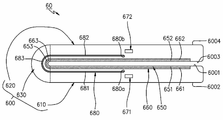
도 6a는 일 실시 예에 따른 전자 장치의 펼쳐진 상태에 관한 단면도이다. 도 6b는 일 실시 예에 따른 전자 장치의 접힌 상태에 관한 단면도이다.6A is a cross-sectional view illustrating an unfolded state of an electronic device according to an embodiment. 6B is a cross-sectional view illustrating a folded state of an electronic device according to an embodiment.
도 6a 및 6b를 참조하면, 일 실시 예에서, 전자 장치(60)(예: 도 2의 전자 장치(20))는 폴더블 하우징(600)(예: 도 2 또는 3의 폴더블 하우징(200)), 디스플레이(650)(예: 도 2의 디스플레이(300)), 디지타이저(660), 제 1 자석(671), 제 2 자석(672) 또는 자석 차폐 부재(680) 중 적어도 하나를 포함할 수 있다.6A and 6B, in one embodiment, the electronic device 60 (eg, the
일 실시 예에 따르면, 폴더블 하우징(600)은 도 5a 또는 5b의 폴더블 하우징(500)과 실질적으로 동일할 수 있다. 예를 들어, 폴더블 하우징(600)은, 제 1 면(6001) 및 제 2 면(6002)을 포함하는 제 1 하우징 구조(610), 제 3 면(6003) 및 제 4 면(6004)을 포함하는 제 2 하우징 구조(620), 또는 제 1 하우징 구조(610) 및 제 2 하우징 구조(620)를 연결하는 힌지 구조(630)를 포함할 수 있다.According to one embodiment, the
일 실시 예에 따르면, 디스플레이(650)는 도 5a의 디스플레이(550)와 실질적으로 동일할 수 있고, 예를 들어, 제 1 면(6001)의 적어도 일부를 형성하는 제 1 부분(651), 제 3 면(6003)의 적어도 일부를 형성하는 제 2 부분(652), 및 제 1 부분(651) 및 제 2 부분(652) 사이의 폴딩 부분(653)을 포함할 수 있다.According to an embodiment, the
일 실시 예에 따르면, 디지타이저(660)는 도 5a의 디지타이저(560)와 실질적으로 동일할 수 있다. 예를 들어, 디지타이저(660)는 디스플레이(650)의 제 1 부분(651)에 대응하는 제 3 부분(661), 디스플레이(650)의 제 2 부분(652)에 대응하는 제 4 부분(662), 또는 디스플레이(650)의 폴딩 부분(653)에 대응하는 폴딩 부분(663)을 포함할 수 있다.According to an embodiment, the
일 실시 예에 따르면, 제 1 자석(671)(예: 도 5a의 제 1 자석(571))은 제 1 하우징 구조(610)의 내부에 배치될 수 있고, 제 2 면(6002)의 위에서 볼 때 디지타이저(660)의 제 3 부분(661)과 중첩될 수 있다.According to one embodiment, the first magnet 671 (eg, the
일 실시 예에 따르면, 제 2 자석(672)(예: 도 5a의 제 2 자석(572))은 제 2 하우징 구조(620)의 내부에 배치될 수 있고, 제 4 면(6004)의 위에서 볼 때 디지타이저(660)의 제 4 부분(662)과 중첩될 수 있다.According to one embodiment, the second magnet 672 (eg, the
일 실시 예에 따르면, 자석 차폐 부재(680)는 자기력을 차폐할 수 있는 물질을 포함할 수 있고, 폴딩 하우징(600)의 내부에 배치될 수 있다. 예를 들어, 자석 차폐 부재(680)는 제 1 하우징 구조(610)에 위치하는 일단부(680a)에서 제 2 하우징 구조(620)에 위치하는 타단부(680b)로 연장된 일체의 플레이트를 포함할 수 있다.According to an embodiment, the
일 실시 예에 따르면, 자석 차폐 부재(680)는 힌지 구조(630)에 고정되는 폴딩 부분(683), 폴딩 부분(683)으로부터 제 1 하우징 구조(610)로 연장된 제 5 부분(681), 또는 폴딩 부분(683)으로부터 제 2 하우징 구조(620)로 연장된 제 6 부분(682)을 포함할 수 있다. 펼쳐진 상태에서(도 6a 참조), 제 2 면(6002)의 위에서 볼 때 자석 차폐 부재(680)의 제 5 부분(681)은 제 1 자석(671)과 중첩할 수 있다. 접힌 상태에서(도 6b 참조), 제 2 면(6002)의 위에서 볼 때 자석 차폐 부재(680)의 제 5 부분(681)은 제 1 자석(671)과 중첩하지 않을 수 있다. 펼쳐진 상태에서, 제 4 면(6004)의 위에서 볼 때 자석 차폐 부재(680)의 제 6 부분(682)은 제 2 자석(672)과 중첩할 수 있다. 접힌 상태에서, 제 4 면(6004)의 위에서 볼 때 자석 차폐 부재(680)의 제 6 부분(682)은 제 2 자석(672)과 중첩하지 않을 수 있다.According to one embodiment, the
일 실시 예에 따르면, 펼쳐진 상태(도 6a 참조) 및 접힌 상태(도 6b 참조) 사이를 변경할 때, 제 1 및 2 하우징 구조들(610, 620) 및 힌지 구조(630) 간의 위치 관계로 인해 자석 차폐 부재(680)는 제 1 하우징 구조(610) 및 제 2 하우징 구조(620)에 대하여 이동될 수 있다. 예를 들어, 펼쳐진 상태에서 접힌 상태로 변경될 때, 자석 차폐 부재(680)는 제 2 면(6002)의 위에서 볼 때 제 1 자석(671)과 중첩하지 않도록 이동될 수 있고, 제 4 면(6004)의 위에서 볼 때 제 2 자석(672)과 중첩하지 않도록 이동될 수 있다. 예를 들어, 접힌 상태에서 펼쳐진 상태로 변경될 때, 자석 차폐 부재(680)는 제 2 면(6002)의 위에서 볼 때 제 1 자석(671)과 중첩하도록 이동될 수 있고, 제 4 면(6004)의 위에서 볼 때 제 2 자석(672)과 중첩하지 않도록 이동될 수 있다.According to one embodiment, when changing between the unfolded state (see FIG. 6A) and the folded state (see FIG. 6B ), the magnets due to the positional relationship between the first and
일 실시 예에 따르면, 자석 차폐 부재(680)의 적어도 일부분은 가요성을 가질 수 있다. 예를 들어, 자석 차폐 부재(680)의 폴딩 부분(683)은 접힌 상태에서(도 6b 참조) 곡형(예: 곡률을 가지는 곡형)으로 배치될 수 있다. 일 실시 예에 따르면, 자석 차폐 부재(680)는 설정된 두께(예: 5 mm 이하)를 가지는 플레이트로 형성되어 휘어짐을 가능하게 할 수 있다.According to one embodiment, at least a portion of the
일 실시 예에 따르면, 자석 차폐 부재(680)의 제 5 부분(681)은 디스플레이(650)와 평행하게 배치될 수 있다. 펼쳐진 상태에서 접힌 상태로 변경되면, 자석 차폐 부재(680)의 제 5 부분(681)은 제 2 면(6002)의 위에서 볼 때 제 1 자석(671)과 중첩되지 않도록 이동될 수 있다. 접힌 상태에서 펼쳐진 상태로 변경되면, 자석 차폐 부재(680)의 제 5 부분(681)은 제 2 면(6002)의 위에서 볼 때 제 1 자석(671)과 중첩되도록 이동될 수 있다.According to an embodiment, the
일 실시 예에 따르면, 자석 차폐 부재(680)의 제 6 부분(682)은 디스플레이(650)와 평행하게 배치될 수 있다. 펼쳐진 상태에서 접힌 상태로 변경되면, 자석 차폐 부재(680)의 제 6 부분(682)은 제 4 면(6004)의 위에서 볼 때 제 2 자석(672)과 중첩되지 않도록 이동될 수 있다. 접힌 상태에서 펼쳐진 상태로 변경되면, 자석 차폐 부재(680)의 제 6 부분(682)은 제 4 면(6004)의 위에서 볼 때 제 2 자석(672)과 중첩되도록 이동될 수 있다.According to an embodiment, the
일 실시 예에 따르면, 자석 차폐 부재(680)는, 접힌 상태 및 펼쳐진 상태 사이를 변경할 때 그 이동을 위해 가해지는 힘에 의해 늘어나거나 줄어들지 않도록 내구성을 가지도록 구현될 수 있다.According to one embodiment, the
일 실시 예에 따르면, 접힌 상태에서(도 6b 참조), 제 1 자석(671) 및 제 2 자석(672)은 서로 정렬하도록 또는 대면하도록 배치될 수 있다. 접힌 상태에서, 제 1 자석(671) 및 제 2 자석(672)의 사이에는 디스플레이(650)의 제 1 부분(651) 및 제 2 부분(652), 및 디지타이저(660)의 제 3 부분(661) 및 제 4 부분(662)이 배치될 수 있다. 일 실시 예에 따르면, 전자 장치(60)의 접힌 상태는 제 1 자석(671) 및 제 2 자석(672) 사이의 인력에 의해 유지될 수 있다.According to one embodiment, in the folded state (see FIG. 6B ), the
일 실시 예에 따르면, 자석 차폐 부재(680)는, 도 5a 및 5b의 자석 차폐 부재들(581, 582)과 마찬가지로, 펼쳐진 상태에서(도 6a 참조) 제 1 자석(671) 및 제 2 자석(672)이 전자 장치(60)에 미치는 영향을 줄일 수 있다. According to one embodiment, the
도 7a는 일 실시 예에 따른 전자 장치의 펼쳐진 상태에 관한 단면도이다. 도 7b는 일 실시 예에 따른 전자 장치의 접힌 상태에 관한 단면도이다.7A is a cross-sectional view illustrating an unfolded state of an electronic device according to an embodiment. 7B is a cross-sectional view illustrating a folded state of an electronic device according to an embodiment.
도 7a 및 7b를 참조하면, 일 실시 예에서, 전자 장치(70)(예: 도 2의 전자 장치(20))는 폴더블 하우징(700)(예: 도 2 또는 3의 폴더블 하우징(200)), 디스플레이(750)(예: 도 2의 디스플레이(300)), 디지타이저(760), 자석(770) 또는 자석 차폐 부재(780) 중 적어도 하나를 포함할 수 있다.7A and 7B, in one embodiment, the electronic device 70 (eg, the
일 실시 예에 따르면, 폴더블 하우징(700)은 도 5a 또는 5b의 폴더블 하우징(500)과 실질적으로 동일할 수 있다. 예를 들어, 폴더블 하우징(700)은, 제 1 면(7001) 및 제 2 면(7002)을 포함하는 제 1 하우징 구조(710), 제 3 면(7003) 및 제 4 면(7004)을 포함하는 제 2 하우징 구조(720), 또는 제 1 하우징 구조(710) 및 제 2 하우징 구조(720)를 연결하는 힌지 구조(730)를 포함할 수 있다.According to one embodiment, the
일 실시 예에 따르면, 디스플레이(750)는 도 5a의 디스플레이(550)와 실질적으로 동일할 수 있고, 예를 들어, 제 1 면(7001)의 적어도 일부를 형성하는 제 1 부분(751), 제 3 면(7003)의 적어도 일부를 형성하는 제 2 부분(752), 및 제 1 부분(751) 및 제 2 부분(752) 사이의 폴딩 부분(753)을 포함할 수 있다.According to one embodiment, the
일 실시 예에 따르면, 디지타이저(760)는 도 5a의 디지타이저(560)와 실질적으로 동일할 수 있다. 예를 들어, 디지타이저(760)는 디스플레이(750)의 제 1 부분(751)에 대응하는 제 3 부분(761), 디스플레이(750)의 제 2 부분(752)에 대응하는 제 4 부분(762), 또는 디스플레이(750)의 폴딩 부분(753)에 대응하는 폴딩 부분(763)을 포함할 수 있다.According to an embodiment, the
일 실시 예에 따르면, 자석(770)은 제 2 하우징 구조(720)의 내부에 배치될 수 있고, 제 4 면(7004)의 위에서 볼 때 디지타이저(760)의 제 4 부분(762)과 중첩될 수 있다. 자석(770)은 도 5a의 제 2 자석(572)과 실질적으로 유사하거나 동일하므로, 이에 대한 상세한 설명은 생략한다.According to one embodiment, the
일 실시 예에 따르면, 자석 차폐 부재(780)는 폴딩 하우징(700)의 내부에 배치될 수 있다. 예를 들어, 자석 차폐 부재(780)는 제 1 하우징 구조(710)에 위치하는 일단부(780a)에서 제 2 하우징 구조(720)에 위치하는 타단부(780b)로 연장된 플레이트로서, 자기력을 차폐할 수 있는 철과 같은 물질을 포함할 수 있다.According to an embodiment, the
일 실시 예에 따르면, 자석 차폐 부재(780)는 힌지 구조(730)에 고정되는 폴딩 부분(783), 폴딩 부분(783)으로부터 제 1 하우징 구조(710)로 연장된 제 5 부분(781), 또는 폴딩 부분(783)으로부터 제 2 하우징 구조(720)로 연장된 제 6 부분(782)을 포함할 수 있다.According to one embodiment, the
일 실시 예에 따르면, 펼쳐진 상태(도 7a 참조) 및 접힌 상태(도 7b 참조) 사이를 변경할 때, 제 1 및 제 2 하우징 구조들(710, 720) 및 힌지 구조(730) 간의 위치 관계로 인해 자석 차폐 부재(780)는 제 1 하우징 구조(710) 및 제 2 하우징 구조(720)에 대하여 이동될 수 있다.According to one embodiment, when changing between the expanded state (see FIG. 7A) and the folded state (see FIG. 7B ), due to the positional relationship between the first and
예를 들어, 접힌 상태(도 7b 참조)에서 펼쳐진 상태(도 7a 참조)로 변경될 때, 자석 차폐 부재(780)의 제 6 부분(782)은 제 2 면(7002)의 위에서 볼 때 자석(770)과 중첩하도록 이동될 수 있다. 일 실시 예에 따르면, 자석 차폐 부재(780)의 제 6 부분(782)은, 도 5a 및 5b의 자석 차폐 부재들(581, 582)과 마찬가지로, 펼쳐진 상태에서 자석(770)이 전자 장치(70)에 미치는 영향을 줄일 수 있다.For example, when changing from the folded state (see Fig. 7B) to the unfolded state (see Fig. 7A), the
예를 들어, 펼쳐진 상태에서 접힌 상태로 변경될 때, 자석 차폐 부재(780)의 제 6 부분(782)은 제 4 면(7004)의 위에서 볼 때 자석(770)과 중첩하지 않도록 이동될 수 있다. 접힌 상태에서, 자석 차폐 부재(780)의 제 5 부분(781)은 제 2 면(7002)의 위에서 볼 때 자석(770)과 중첩될 수 있다. 전자 장치(700)의 접힌 상태는 자석(770) 및 제 5 부분(781) 사이의 인력으로 인해 유지될 수 있다. 접힌 상태에서, 자석(770) 및 자석 차폐 부재(780)의 제 5 부분(781) 사이의 인력은 디스플레이(750)의 탄력(예: 폴딩 부분(753)이 휘어진 상태에서 펴지려는 복원력)에 대응하여 접힌 상태를 유지하게 할 수 있다.For example, when changing from the expanded state to the folded state, the
일 실시 예에 따르면, 자석 차폐 부재(780)의 적어도 일부분은 가요성을 가질 수 있다. 예를 들어, 자석 차폐 부재(780)의 폴딩 부분(783)은 접힌 상태에서(도 7b 참조) 곡형(예: 곡률을 가지는 곡형)으로 배치될 수 있다. 일 실시 예에 따르면, 자석 차폐 부재(780)는 설정된 두께(예: 5 mm 이하)를 가지는 플레이트로 형성되어 휘어짐을 가능하게 할 수 있다.According to one embodiment, at least a portion of the
일 실시 예에 따르면, 자석 차폐 부재(780)는, 접힌 상태 및 펼쳐진 상태 사이를 변경할 때 그 이동을 위해 가해지는 힘에 의해 늘어나거나 줄어들지 않도록 내구성을 가지도록 구현될 수 있다.According to an embodiment, the
어떤 실시 예에 따르면(미도시), 자석 차폐 부재(780)는 도 5b의 실시 예에서와 같이 분리된 제 1 자석 차폐 부재(581) 및 제 2 자석 차폐 부재(582)로 구현될 수도 있다.According to some embodiments (not shown), the
어떤 실시 예에 따르면(미도시), 자석 차폐 부재(780) 중 힌지 구조(730)에 고정되는 폴딩 부분(783)으로부터 제 1 하우징 구조(710)로 연장된 제 5 부분(781)은 생략될 수 있다. 전자 장치(70)는 접힌 상태(도 7b 참조)에서 자석(770)과 정렬하거나 대면하는 별도의 자성체 부재를 포함할 수 있다. 자성체 부재는 디지타이저(660)의 제 3 부분(761) 및 제 2 면(7002) 사이에 배치될 수 있다. 자성체 부재는 접힌 상태 또는 펼쳐진 상태와 무관하게 제 1 하우징 구조(710)의 설정된 위치에 배치될 수 있다. 전자 장치(70)의 접힌 상태는 자석(770) 및 자성체 부재 사이의 인력에 의해 유지될 수 있다.According to some embodiments (not shown), the
도 8a는 일 실시 예에 따른 펼쳐진 상태의 전자 장치에 대한 전개 사시도이다. 도 8b는 일 실시 예에 따른 펼쳐진 상태의 전자 장치에 대한 단면도이다. 도 8c는 일 실시 예에 따른 전자 장치에 관한 사시도이다. 도 8d는 일 실시 예에 따른 제 1 가이드 장치에 관한 전개 사시도이다. 도 8e는 일 실시 예에 따른 전자 장치의 사시도이다.8A is an exploded perspective view of an unfolded electronic device according to an embodiment. 8B is a cross-sectional view of an unfolded electronic device according to an embodiment. 8C is a perspective view of an electronic device according to an embodiment. 8D is an exploded perspective view of a first guide device according to an embodiment. 8E is a perspective view of an electronic device according to an embodiment.
도 8a, 8b 및 8c를 참조하면, 일 실시 예에서, 전자 장치(800)는 제 1 하우징 구조(810), 제 2 하우징 구조(820), 힌지 구조(830), 디스플레이(850), 디지타이저(860), 제 1 자석(871), 제 2 자석(872), 자석 차폐 부재(880), 제 1 가이드 장치(891) 또는 제 2 가이드 장치(892) 중 적어도 하나를 포함할 수 있다. 다양한 실시 예에 따르면, 전자 장치(800)는 도 2의 전자 장치(20), 또는 도 6a의 전자 장치(60)를 포함할 수 있다. 예를 들어, 제 1 하우징 구조(810)는 도 2의 제 1 하우징 구조(210), 또는 도 6a의 제 1 하우징 구조(610)를 포함할 수 있다. 예를 들어, 제 2 하우징 구조(820)는 도 2의 제 2 하우징 구조(220) 또는 도 6a의 제 2 하우징 구조(620)를 포함할 수 있다. 예를 들어, 힌지 구조(830)는 도 4의 힌지 구조(401), 또는 도 6a의 힌지 구조(630)를 포함할 수 있다. 예를 들어, 디스플레이(850)는 도 2의 디스플레이(300) 또는 도 6a의 디스플레이(650)를 포함할 수 있다. 예를 들어, 디지타이저(860)는 도 6a의 디지타이저(660)를 포함할 수 있다. 예를 들어, 제 1 자석(871)은 도 6a의 제 1 자석(671)을 포함할 수 있다. 예를 들어, 제 2 자석(872)은 도 6a의 제 2 자석(672)을 포함할 수 있다.8A, 8B, and 8C, in one embodiment, the
일 실시 예에 따르면, 제 1 하우징 구조(810) 및 제 2 하우징 구조(820)는 힌지 구조(830)와 연결되어 힌지 구조(830)를 중심으로 상호 회동 가능할 수 있다.According to an embodiment, the
일 실시 예에 따르면, 디스플레이(850)는 제 1 하우징 구조(810) 및 제 2 하우징 구조(820)와 결합될 수 있다. 예를 들어, 디스플레이(850)는 제 1 하우징 구조(810)에 대응하는 제 1 부분(851)(예: 도 6a의 제 1 부분(651)), 제 2 하우징 구조(820)에 대응하는 제 2 부분(852)(예: 도 6a의 제 2 부분(652)), 및 힌지 구조(830)에 대응하는 폴딩 부분(853)(예: 도 6a의 폴딩 부분(653))을 포함할 수 있다. 펼쳐진 상태에서, 폴딩 부분(853)은 실질적으로 제 1 부분(851) 및 제 2 부분(852)과 동일 평면을 형성할 수 있다. 접힌 상태에서(도 3 참조), 폴딩 부분(853)은 곡형으로 휘어져 배치될 수 있고, 제 1 부분(851) 및 제 2 부분(852)은 대면하게 배치될 수 있다.According to an embodiment, the
일 실시 예에 따르면, 디지타이저(860)는 디스플레이(850)의 배면(850b)의 적어도 일부를 따라 디스플레이(850)와 결합되거나 인접하여 배치될 수 있다. 예를 들어, 디지타이저(860)는 디스플레이(850)의 제 1 부분(851)을 따라 배치된 제 3 부분(861)(예: 도 6a의 제 3 부분(661)), 디스플레이(850)의 제 2 부분(852)을 따라 배치된 제 4 부분(862)(예: 도 6a의 제 4 부분(662)), 및 디스플레이(850)의 폴딩 부분(853)을 따라 배치된 폴딩 부분(863)(예: 도 6a의 폴딩 부분(663))을 포함할 수 있다.According to an embodiment, the
일 실시 예에 따르면, 제 1 하우징 구조(810)는 제 1 지지 부재(814)(예: 도 4의 제 1 지지 부재(410)), 제 1 측면 부재(813)(예: 도 2의 제 1 측면 부재(211)), 제 1 내부 지지 부재(811) 또는 제 1 후면 커버(812)(예: 도 2의 제 1 후면 커버(280))를 포함할 수 있다. 제 1 지지 부재(814)는 디스플레이(850)의 제 1 부분(851) 및 디지타이저(860)의 제 3 부분(861)을 전자 장치(800)에 배치 또는 고정하기 위한 설치 판(mounting plate) 또는 브라켓(bracket)을 포함할 수 있다. 다양한 실시 예에 따르면, 제 1 지지 부재(814)의 일부(814d)는 제 1 후면 커버(812)와 함께 전자 장치(800)의 외면(예: 도 2의 후면(200b)) 일부를 형성하도록 연장될 수 있다. 제 1 내부 지지 부재(811)는, 예를 들어, 제 1 인쇄 회로 기판(예: 도 4의 제 1 기판(451))과 같은 요소를 전자 장치(800)에 배치 또는 고정하기 위한 설치 판 또는 브라켓을 포함할 수 있다. 제 1 측면 부재(813)는 제 1 하우징 구조(810)의 측면을 형성할 수 있다. 일 실시 예에 따르면, 제 1 측면 부재(813)는 제 1 지지 부재(814)와 일체로 형성되어 제 1 지지 부재(814)와 동일한 물질을 포함할 수 있다.According to one embodiment, the
일 실시 예에 따르면, 제 2 하우징 구조(820)는 제 2 지지 부재(824)(예: 도 4의 제 2 지지 부재(420)), 제 2 측면 부재(823)(예: 도 2의 제 2 측면 부재(221)), 제 2 내부 지지 부재(821) 또는 제 2 후면 커버(822)(예: 도 2의 제 2 후면 커버(290))를 포함할 수 있다. 제 2 지지 부재(821)는 디스플레이(850)의 제 2 부분(852) 및 디지타이저(860)의 제 4 부분(862)을 전자 장치(800)에 배치 또는 고정하기 위한 설치 판 또는 브라켓을 포함할 수 있다. 다양한 실시 예에 따르면, 제 2 지지 부재(824)의 일부(824d)는 제 2 후면 커버(822)와 함께 전자 장치(800)의 외면(예: 도 2의 후면(200b)) 일부를 형성하도록 연장될 수 있다. 제 2 내부 지지 부재(821)는 제 2 인쇄 회로 기판(예: 도 4의 제 2 기판(452))을 전자 장치(800)에 배치 또는 고정하기 위한 설치 판 또는 브라켓을 포함할 수 있다. 제 2 측면 부재(823)는 제 2 하우징 구조(820)의 측면을 형성할 수 있다. 일 실시 예에 따르면, 제 2 측면 부재(823)는 제 2 지지 부재(824)와 일체로 형성되어 제 2 지지 부재(824)와 동일한 물질을 포함할 수 있다.According to one embodiment, the
일 실시 예에 따르면, 힌지 구조(830)는 제 1 힌지 플레이트(831), 제 2 힌지 플레이트(832), 적어도 하나의 힌지(834) 또는 힌지 커버(833)(예: 도 3의 힌지 커버(230)) 중 적어도 하나를 포함할 수 있다. 제 1 힌지 플레이트(831) 및 제 2 힌지 플레이트(832)는 적어도 하나의 힌지(834)에 의해 회전 가능하게 연결될 수 있다. 제 1 힌지 플레이트(831)는 제 1 지지 부재(814)와 결합될 수 있다. 제 2 힌지 플레이트(832)는 제 2 지지 부재(824)와 결합될 수 있다. 적어도 하나의 힌지(834)로 연결된 제 1 힌지 플레이트(831) 및 제 2 힌지 플레이트(832)로 인해, 제 1 지지 부재(814)를 포함하는 제 1 하우징 구조(810) 및 제 2 지지 부재(824)를 포함하는 제 2 하우징 구조(820)는 힌지 구조(830)를 중심으로 상호 회동 가능할 수 있다.According to one embodiment, the
일 실시 예에 따르면, 디스플레이(850) 및 디지타이저(860)는 제 1 지지 부재(814) 및 제 2 지지 부재(824)에 배치되어 제 1 하우징 구조(810) 및 제 2 하우징 구조(820)가 힌지 구조(830)를 중심으로 이루는 각도에 따라 폴딩 부분들(853, 863)을 중심으로 펼쳐지거나 또는 접힐 수 있다.According to one embodiment, the
일 실시 예에 따르면, 제 1 힌지 플레이트(831)의 일부는 디지타이저(860) 및 제 1 지지 부재(814) 사이로 연장될 수 있고, 제 1 지지 부재(814)와 함께 디지타이저(860)를 배치하기 위한 면(이하, 제 1 실장 면)(8001)을 형성할 수 있다. 일 실시 예에 따르면, 제 2 힌지 플레이트(832)의 일부는 디지타이저(860) 및 제 2 지지 부재(824) 사이로 연장될 수 있고, 제 2 지지 부재(824)와 함께 디지타이저(860)를 배치하기 위한 면(이하, 제 2 실장 면)(8002)을 형성할 수 있다.According to one embodiment, a portion of the
일 실시 예에 따르면, 힌지 커버(833)는 제 1 하우징 구조(810) 및 제 2 하우징 구조(820) 사이에 배치될 수 있다. 힌지 커버(833)는, 전자 장치(800)의 펼쳐진 상태 또는 접힌 상태(도 3 참조)에 따라, 제 1 하우징 구조(810) 및 제 2 하우징 구조(820)의 일부에 의해 가려지거나, 외부로 노출될 수 있다.According to an embodiment, the
일 실시 예에 따르면, 제 1 지지 부재(814)는 펼쳐진 상태에서 힌지 커버(833)와 대면하는 제 1 회전 지지면(814c)(예: 도 4의 제 1 회전 지지면(212))을 포함할 수 있다. 일 실시 예에 따르면, 제 2 지지 부재(824)는 펼쳐진 상태에서 힌지 커버(833)와 대면하는 제 2 회전 지지면(824c)(예: 도 4의 제 2 회전 지지면(222))을 포함할 수 있다.According to one embodiment, the
일 실시 예에 따르면, 전자 장치(800)가 펼쳐진 상태에 있을 때, 제 1 회전 지지면(814c) 및 제 2 회전 지지면(824c)은 힌지 커버(833)를 덮을 수 있고, 힌지 커버(833)는 외부로 노출되지 않거나 최소한으로 노출될 수 있다. 전자 장치(800)가 접힌 상태에 있을 때(도 3 참조), 힌지 커버(833)는 제 1 회전 지지면(814c) 및 제 2 회전 지지면(824c) 사이에서 노출될 수 있다.According to one embodiment, when the
일 실시 예에 따르면, 전자 장치(800)가 펼쳐진 상태에 있을 때, 힌지 커버(833)는 제 1 회전 지지면(814c) 및 제 2 회전 지지면(824c)과 적어도 일부 대면하는 곡면(833b)을 포함할 수 있다. 일 실시 예에 따르면, 제 1 회전 지지면(814c) 및/또는 제 2 회전 지지면(824c)은 힌지 커버(833)의 곡면(833b)에 대응하는 곡면(미도시)을 포함할 수 있다. 전자 장치(800)가 접힌 상태에 있을 때(도 3 참조), 상기 곡면(833b)의 적어도 일부는 전자 장치(800)의 한쪽 측면의 적어도 일부를 형성할 수 있다. 일 실시 예에 따르면, 단면으로 볼 때, 힌지 커버(833)는 곡형(curved shape)을 포함할 수 있다.According to an embodiment of the present disclosure, when the
일 실시 예에 따르면, 제 1 자석(871)은 제 1 지지 부재(814) 및 제 1 내부 지지 부재(811) 사이에 배치될 수 있다. 예를 들어, 제 1 자석(871)은 제 1 내부 지지 부재(811)에 고정될 수 있다. 어떤 실시 예에 따르면, 제 1 자석(871)은 제 1 내부 지지 부재(811) 및 제 1 후면 커버(812) 사이에 배치될 수 있고, 제 1 내부 지지 부재(811) 또는 제 1 후면 커버(812)에 고정될 수도 있다. 일 실시 예에 따르면, 제 1 자석(871)은 디스플레이(850)의 제 1 부분(851) 위에서 볼 때 디지타이저(860)의 제 3 부분(861)과 중첩될 수 있다.According to an embodiment, the
다양한 실시 예에 따르면, 제 1 자석(871)은 제 1 내부 지지 부재(811)에 마련된 리세스(recess)(또는, 리세스를 포함하는 구조)(8111)에 배치될 수 있다. 예를 들어, 리세스(8111)는 제 1 자석(871)을 끼워 맞출 수 있는 공간을 제공할 수 있다. 어떤 실시 예에 따르면, 제 1 자석(871)은 제 1 내부 지지 부재(811)의 내부에 배치될 수도 있다.According to various embodiments, the
일 실시 예에 따르면, 제 2 자석(872)은 제 2 지지 부재(824) 및 제 2 내부 지지 부재(821) 사이에 배치될 수 있다. 예를 들어, 제 2 자석(872)은 제 2 내부 지지 부재(821)에 고정될 수 있다. 어떤 실시 예에 따르면, 제 2 자석(872)은 제 2 내부 지지 부재(821) 및 제 2 후면 커버(822) 사이에 배치될 수 있고, 제 2 내부 지지 부재(821) 또는 제 2 후면 커버(822)에 고정될 수도 있다. 일 실시 예에 따르면, 제 2 자석(872)은 디스플레이(850)의 제 2 부분(852) 위에서 볼 때 디지타이저(860)의 제 4 부분(862)과 중첩될 수 있다. 예를 들어, 제 2 자석(872)은 도 6a의 제 2 자석(672)을 포함할 수 있다.According to an embodiment, the
다양한 실시 예에 따르면, 제 2 자석(872)은 제 2 내부 지지 부재(821)에 마련된 리세스(또는, 리세스를 포함하는 구조)(8211)에 배치될 수 있다. 예를 들어, 리세스(8211)는 제 2 자석(872)을 끼워 맞출 수 있는 형태로 형성될 수 있다. 어떤 실시 예에 따르면, 제 2 자석(872)은 제 2 내부 지지 부재(821)의 내부에 배치될 수도 있다.According to various embodiments, the
일 실시 예에 따르면, 자석 차폐 부재(880)(예: 도 6a의 자석 차폐 부재(680))는 자기력을 차폐할 수 있는 물질을 포함할 수 있다. 자석 차폐 부재(880)는 제 1 하우징 구조(810)에 위치하는 일단부(880a)에서 제 2 하우징 구조(820)에 위치하는 타단부(880b)로 연장된 일체의 플레이트를 포함할 수 있다. 일 실시 예에 따르면, 자석 차폐 부재(880)는 힌지 구조(830)에 고정되는 폴딩 부분(883)(예: 도 6a의 폴딩 부분(683)), 폴딩 부분(883)으로부터 제 1 하우징 구조(810)로 연장된 제 1 연장부(881)(예: 도 6a의 제 5 부분(681)), 또는 폴딩 부분(883)으로부터 제 2 하우징 구조(820)로 연장된 제 2 연장부(882)(예: 도 6a의 제 6 부분(682))를 포함할 수 있다. 제 1 연장부(881)는 제 1 실장면(8001) 및 디지타이저(860)의 제 3 부분(861) 사이에 배치될 수 있고, 제 2 연장부(882)는 제 2 실장면(8002) 및 디지타이저(860)의 제 4 부분(862) 사이에 배치될 수 있다.According to an embodiment, the magnetic shield member 880 (eg, the
일 실시 예에 따르면, 자석 차폐 부재(880)의 폴딩 부분(883)은 볼트(885)를 이용하여 힌지 구조(830)와 결합될 수 있다. 예를 들어, 자석 차폐 부재(880)의 폴딩 부분(883)은 볼트 체결을 위한 관통 홀(8831)을 포함할 수 있다. 힌지 구조(830)는 힌지 커버(833) 및 힌지 플레이트들(831, 832) 사이의 공간에 배치된 구조물(835)을 포함할 수 있다. 상기 구조물(835)은 힌지 커버(833)와 결합될 수 있고, 상기 관통 홀(8831)과 정렬되어 볼트(885)에 의해 체결되는 홀 또는 리세스(8351)를 포함할 수 있다. 다양한 실시 예에 따르면, 상기 구조물(835)은 힌지 커버(833)와 일체로 형성될 수 있고, 힌지 커버(833)와 동일한 물질을 포함할 수 있다.According to one embodiment, the
일 실시 예에 따르면, 펼쳐진 상태에서, 디스플레이(850)의 위에서 볼 때 자석 차폐 부재(880)의 제 1 연장부(881)의 적어도 일부는 제 1 자석(871)과 중첩할 수 있다. 접힌 상태에서(도 6b 참조), 제 1 후면 커버(812)의 위에서 볼 때 자석 차폐 부재(880)의 제 1 연장부(881)는 제 1 자석(871)과 중첩하지 않을 수 있다. 일 실시 예에 따르면, 펼쳐진 상태에서, 디스플레이(850)의 위에서 볼 때 자석 차폐 부재(880)의 제 2 연장부(882)의 적어도 일부는 제 2 자석(872)과 중첩할 수 있다. 접힌 상태에서(도 6b 참조), 제 2 후면 커버(822)의 위에서 볼 때 자석 차폐 부재(880)의 제 2 연장부(882)는 제 2 자석(872)과 중첩하지 않을 수 있다.According to an embodiment, when viewed from the top of the
예를 들어, 펼쳐진 상태 및 접힌 상태(도 6b 참조) 사이를 변경할 때, 제 1 및 2 하우징 구조들(810, 820) 및 힌지 구조(830) 간의 위치 관계로 인해 자석 차폐 부재(880)는 제 1 하우징 구조(810) 및 제 2 하우징 구조(820)에 대하여 이동될 수 있다. 일 실시 예에 따르면, 펼쳐진 상태에서 접힌 상태로 변경될 때, 자석 차폐 부재(880)의 제 1 연장부(881)는 제 1 후면 커버(812)의 위에서 볼 때 제 1 자석(871)과 중첩하지 않도록 이동될 수 있고, 자석 차폐 부재(880)의 제 2 연장부(882)는 제 2 후면 커버(822)의 위에서 볼 때 제 2 자석(872)과 중첩하지 않도록 이동될 수 있다. 일 실시 예에 따르면, 접힌 상태에서 펼쳐진 상태로 변경될 때, 자석 차폐 부재(880)의 제 1 연장부(881)는 디스플레이(850)의 위에서 볼 때 제 1 자석(871)과 중첩하도록 이동될 수 있고, 자석 차폐 부재(880)의 제 2 연장부(882)는 디스플레이(850)의 위에서 볼 때 제 2 자석(872)과 중첩하도록 이동될 수 있다.For example, when changing between the unfolded state and the folded state (see FIG. 6B ), the
도 8a, 8b, 8c 및 8d를 참조하면, 일 실시 예에서, 제 1 가이드 장치(891)는, 자석 차폐 부재(880)의 제 1 연장부(881)가 제 1 실장면(8001)과 대면하게 배치되도록 하면서, 펼쳐진 상태 및 접힌 상태(도 6b 참조) 사이를 변경할 때 그 이동을 안내할 수 있다. 제 1 지지 부재(814)는 디지타이저(860)와 대면하는 제 1 면(814a)과, 제 1 면(814a)과는 반대로 향하는 제 2 면(814b)을 포함할 수 있다. 일 실시 예에 따르면, 제 1 가이드 장치(891)는 제 1 지지 부재(814) 및 제 1 내부 지지 부재(811) 사이에 배치되는 제 1 링크(link)(8911)를 포함할 수 있다. 제 1 링크(8911)는 제 1 지지 부재(814)의 제 2 면(814b)에 회전 가능하게 결합되는 제 1 조인트(891a)를 포함할 수 있다. 제 1 조인트(891a)는 관통 홀을 포함할 수 있고, 제 1 지지 부재(814)는 제 2 면(814b)에 형성되어 상기 관통 홀에 삽입되는 샤프트(shaft)(8141)를 포함할 수 있다. 제 1 가이드 장치(891)는 샤프트(8141)에 결합되는 볼트(891e)를 포함할 수 있고, 볼트(891e)는, 제 1 조인트(891a)가 샤프트(8141)로부터 이탈되는 것을 방지할 수 있다.8A, 8B, 8C, and 8D, in one embodiment, in the
일 실시 예에 따르면, 제 1 링크(8911)는 핀(891d)을 통해 자석 차폐 부재(880)의 제 1 연장부(881)와 회전 가능하게 연결되는 제 2 조인트(891b)를 포함할 수 있다. 제 1 지지 부재(814)는 제 1 면(814a) 및 제 2 면(814b) 사이를 관통하는 슬릿(slit)(8142)을 포함할 수 있다. 자석 차폐 부재(880)의 제 1 연장부(881)는 관통 홀(8811)을 포함할 수 있다. 핀(891d)은 헤드(head)(894)와, 헤드(894)와 연결된 연장부(extension)(893)를 포함할 수 있다. 핀(891d)의 연장부(893)가 자석 차폐 부재(880)의 관통 홀(8811) 및 제 1 지지 부재(814)의 슬릿(8142)을 관통한 후 제 1 링크(8911)의 제 2 조인트(891b)와 체결되는 방식에 의해, 자석 차폐 부재(880)의 제 1 연장부(881)는 제 1 링크(8911)의 제 2 조인트(891b)와 연결될 수 있다. 일 실시 예에 따르면, 핀(891d)의 연장부(893)는 양 갈래로 연장된 구조로서 그 단부들(8931, 8932)은 제 2 조인트(891b)와 탄력적으로 결합될 수 있다. 예를 들어, 제 2 조인트(891b)는 턱(또는, 단차 턱)(891cc)을 포함하는 관통 홀(891c)을 포함할 수 있고, 핀(891d)의 연장부(893)에 형성된 단부들(8931, 8932)은 후크(hook)와 같이 작용하여 턱(891cc)에 체결될 수 있다 (예: 스냅 핏(snap-fit) 체결). 핀(891d)의 헤드(894)는 자석 차폐 부재(880)의 제 1 연장부(881)에 형성된 관통 홀(8811)의 지름 보다 넓은 너비를 가지도록 형성되어, 자석 차폐 부재(880)의 제 1 연장부(881)는 제 1 지지 부재(814)의 제 1 면(814a)과 대면하여 배치될 수 있다.According to one embodiment, the
일 실시 예에 따르면, 제 2 조인트(891b)에 형성된 관통 홀(891c)은 제 1 조인트(891a)로 향하는 방향(8912)으로 연장된 슬릿(slit)일 수 있다. 일 실시 예에 따르면, 제 1 지지 부재(814)에 형성된 슬릿(8142)은, 펼쳐진 상태 및 접힌 상태(도 6b 참조) 사이를 변경할 때 자석 차폐 부재(880)의 제 1 연장부(881)가 이동되는 방향(8801)으로 연장된 길이(미도시)를 가질 수 있다. 펼쳐진 상태 및 접힌 상태(도 6b 참조) 사이를 변경할 때, 제 1 링크(8911)는 샤프트(8141)를 중심으로 회전될 수 있고, 제 1 자석 차폐 부재(880)의 제 1 연장부(881)와 연결된 핀(891d)은 제 2 조인트(891b)의 관통 홀(891c) 상에서 위치 이동될 뿐 아니라 제 1 지지 부재(814)에 형성된 슬릿(8142) 상에서 위치 이동될 수 있다.According to an embodiment, the through
다양한 실시 예에 따르면(미도시), 제 1 지지 부재(814)에 형성된 슬릿(8142)은 제 1 힌지 커버(812)의 위에서 볼 때, 샤프트(8141)를 중심으로 해당 각도의 호 형태로 형성된 슬릿으로 대체될 수 있다. 이 경우, 제 2 조인트(891b)의 관통 홀은 핀(891d)의 위치 이동을 허용하지 않는 형태로 형성될 수 있다. 예를 들어, 펼쳐진 상태 및 접힌 상태(도 6b 참조) 사이를 변경할 때, 자석 차폐 부재(880)의 제 1 연장부(881)와 연결된 핀(891d)은 제 1 조인트(891a)와 일정 거리를 유지하면서 제 1 지지 부재(814)에 형성된 호 형태의 슬릿 상에서 위치 이동될 수 있다.According to various embodiments (not shown), the
도 8a, 8b, 8c 및 8e를 참조하면, 일 실시 예에서, 제 2 지지 부재(824)는 디지타이저(860)과 대면하는 제 3 면(824a)과, 제 3 면(824a)과는 반대로 향하는 제 4 면(824b)을 포함할 수 있다. 일 실시 예에 따르면, 제 2 가이드 장치(892)는, 자석 차폐 부재(880)의 제 2 연장부(882)가 제 3 면(824a)과 대면하게 배치되도록 하면서, 펼쳐진 상태 및 접힌 상태(도 6b 참조) 사이를 변경할 때 제 2 연장부(882)의 이동을 안내할 수 있다. 제 2 가이드 장치(892)는 제 1 가이드 장치(891)와 실질적으로 동일한 구조를 가질 수 있고, 이에 대한 상세한 설명은 생략한다. 예를 들어, 제 2 가이드 장치(892)는 제 2 지지 부재(824) 및 자석 차폐 부재(880)와 연결되는 제 2 링크(8921)를 포함할 수 있다. 예를 들어, 제 2 링크(8921)는 제 2 지지 부재(824)의 제 4 면(824b)에 형성된 샤프트(8241)(예: 샤프트(8141))와 회전 가능하게 결합되는 제 3 조인트(892a)(예: 제 1 조인트(891a))를 포함할 수 있다. 예를 들어, 제 1 가이드 장치(892)는 샤프트(8241)에 결합되는 볼트(892e)(예: 볼트(891e))를 포함할 수 있고, 볼트(892e)는, 제 3 조인트(892a)가 샤프트(8241)로부터 이탈되는 것을 방지할 수 있다. 예를 들어, 제 2 링크(8921)는 슬릿(892c)(예: 관통 홀(891c))을 포함하는 제 4 조인트(892b)(예: 제 2 조인트(891b))를 포함할 수 있다. 제 4 조인트(892b)는 제 2 지지 부재(824)에 형성된 슬릿(8242)(예: 슬릿(8142))을 관통하는 핀(892d)(예: 핀(891d))을 통해 자석 차폐 부재(880)의 제 2 연장부(882)에 형성된 관통 홀(8821)과 연결될 수 있다.8A, 8B, 8C, and 8E, in one embodiment, the
다양한 실시 예에 따르면(미도시), 자석 차폐 부재(880), 제 1 가이드 장치(891), 제 2 가이드 장치(892), 제 1 자석(871) 및 제 2 자석(872)을 포함하는 구조는 복수 개 마련될 수 있다.According to various embodiments (not shown), a structure including a
다양한 실시 예에 따르면, 자석 차폐 부재(880)의 적어도 일부분은 가요성을 가질 수 있다. 예를 들어, 자석 차폐 부재(880)의 폴딩 부분(883)은 접힌 상태에서(도 6b 참조) 곡형(예: 곡률을 가지는 곡형)으로 배치될 수 있다. 일 실시 예에 따르면, 자석 차폐 부재(880)는 설정된 두께(예: 5 mm 이하)를 가지는 플레이트로 형성되어 휘어짐을 가능하게 할 수 있다. 다양한 실시 예에 따르면, 자석 차폐 부재(880)는, 접힌 상태 및 펼쳐진 상태 사이를 변경할 때 그 이동을 위해 가해지는 힘에 의해 늘어나거나 줄어들지 않도록 내구성을 가지도록 구현될 수 있다.According to various embodiments, at least a portion of the
일 실시 예에 따르면, 접힌 상태에서(도 6b 참조), 제 1 자석(871) 및 제 2 자석(872)은 서로 정렬하도록 또는 대면하도록 배치될 수 있다. 접힌 상태에서, 제 1 자석(871) 및 제 2 자석(872)의 사이에는 디스플레이(850)의 제 1 부분(851) 및 제 2 부분(852), 및 디지타이저(860)의 제 3 부분(861) 및 제 4 부분(862)이 배치될 수 있다. 일 실시 예에 따르면, 전자 장치(800)의 접힌 상태는 제 1 자석(871) 및 제 2 자석(872) 사이의 인력에 의해 유지될 수 있다.According to an embodiment, in the folded state (see FIG. 6B ), the
일 실시 예에 따르면, 자석 차폐 부재(880)는, 도 6a 및 6b의 자석 차폐 부재들(681, 682)과 마찬가지로, 펼쳐진 상태에서(도 6a 참조) 제 1 자석(871) 및 제 2 자석(872)이 전자 장치(800)에 미치는 영향을 줄일 수 있다. 예를 들어, 펼쳐진 상태에서 자기장을 활용하는 전자 펜(예: 도 2의 전자 펜(460))을 이용하여 입력을 할 때, 제 1 자석 차폐 부재(881)는 제 1 자석(871)으로부터의 자기장이 전자 펜 및 디지타이저(860) 사이의 상호 작용에 미치는 영향을 줄일 수 있다. 예를 들어, 펼쳐진 상태에서 자기장을 활용하는 전자 펜을 이용하여 입력을 할 때, 제 2 자석 차폐 부재(882)는 제 2 자석(872)으로부터의 자기장이 전자 펜 및 디지타이저(860) 사이의 상호 작용에 미치는 영향을 줄일 수 있다.According to one embodiment, the
도 9a는 일 실시 예에 따른 힌지 구조의 전개 사시도이다. 도 9b는 일 실시 예에 따른 힌지의 배면도이다.9A is an exploded perspective view of a hinge structure according to an embodiment. 9B is a rear view of the hinge according to one embodiment.
도 9a를 참조하면, 일 실시 예에서, 힌지 구조(900)(예: 도 4의 힌지 구조(401), 도 5b의 힌지 구조(530), 도 6b의 힌지 구조(630), 도 7b의 힌지 구조(730), 또는 도 8a의 힌지 구조(830))는, 제 1 힌지 플레이트(910)(예: 도 8a의 제 1 힌지 플레이트(831)), 제 2 힌지 플레이트(920)(예: 도 8a의 제 2 힌지 플레이트(832)), 힌지 커버(930)(예: 도 8a의 힌지 커버(833)) 또는 적어도 하나의 힌지(940)(예: 도 8c의 적어도 하나의 힌지(834)) 중 적어도 하나를 포함할 수 있다.9A, in one embodiment, the hinge structure 900 (eg, the
일 실시 예에 따르면, 제 1 힌지 플레이트(910) 및 제 2 힌지 플레이트(920)는 적어도 하나의 힌지(940)에 의해 상호 회전 가능하게 연결될 수 있다. 도 9a 및 9b를 참조하면, 일 실시 예에서, 힌지(940)는 제 3 부분(943), 제 3 부분(943)과 회전 가능하게 연결되고 제 1 힌지 플레이트(910)와 결합되는 제 1 부분(941)을 포함할 수 있다. 힌지(940)는 제 3 부분(943)과 회전 가능하게 연결되고 제 2 힌지 플레이트(920)와 결합되는 제 2 부분(942)을 포함할 수 있다. 제 1 부분(941)과 결합된 제 1 힌지 플레이트(910)는, 제 3 부분(943)을 중심으로 제 2 부분(942)과 결합된 제 2 힌지 플레이트(920)에 대하여 회전 가능할 수 있다.According to one embodiment, the
일 실시 예에 따르면, 힌지(940)의 제 1 부분(941) 및 제 1 힌지 플레이트(910), 및/또는 힌지(940)의 제 2 부분(942) 및 제 2 힌지 플레이트(920)는 볼트(미도시)로 결합될 수 있다. 예를 들어, 제 1 힌지 플레이트(910)는, 제 1 힌지 플레이트(910) 및 제 2 힌지 플레이트(920) 간의 회전 중심 축(C)과 평행하게 배열된 복수의 홀들(911a, 911b, 911c)을 포함할 수 있다. 힌지(940)의 제 1 부분(941)은 제 1 힌지 플레이트(910)의 홀(911a, 911b 또는 911c)과 정렬되어 볼트에 의해 체결되는 홀(941a)을 포함할 수 있다. 예를 들어, 제 2 힌지 플레이트(920)는, 회전 중심 축(C)과 평행하게 배열된 복수의 홀들(921a, 921b, 921c)을 포함할 수 있다. 힌지(940)의 제 2 부분(942)은 제 2 힌지 플레이트(920)의 홀(921a, 921b 또는 921c)과 정렬되어 볼트에 의해 체결되는 홀(942a)을 포함할 수 있다.According to one embodiment, the
일 실시 예에 따르면, 제 1 힌지 플레이트(910)는 제 1 지지 부재(예: 도 8a의 제 1 지지 부재(814))와 볼트로 결합하는데 이용되는 홀들(912a, 912b, 912c, 912d, 912e)을 포함할 수 있다. 일 실시 예에 따르면, 제 2 힌지 플레이트(920)는 제 2 지지 부재(예: 도 8a의 제 2 지지 부재(824))와 볼트로 결하는데 이용되는 홀들(922a, 922b, 922c, 922d, 922e)을 포함할 수 있다.According to one embodiment, the
일 실시 예에 따르면, 힌지(940)의 제 1 부분(941)과 결합된 제 1 힌지 플레이트(910) 및 힌지(940)의 제 2 부분(942)과 결합된 제 2 힌지 플레이트(920)는, 약 180 도의 각도를 이루는 제 1 상태(예: 펼쳐진 상태)에서 설정된 각도(예: 약 90 도)보다 작은 각도를 이루는 상태로 변경되면 더 이상의 외력 없이도 약 0 도에서 10 도 사이의 각도를 이루는 제 2 상태(예: 접힌 상태)로 자동으로 변경될 수 있다. 힌지(940)의 제 1 부분(941)과 결합된 제 1 힌지 플레이트(910) 및 힌지(940)의 제 2 부분(942)과 결합된 제 2 힌지 플레이트(920)는, 상기 제 1 상태(예: 펼쳐진 상태)에서 상기 설정된 각도(예: 약 90 도) 이상의 각도를 이루는 상태로 변경된 후 이에 작용한 외력이 해제되면 상기 제 1 상태로 자동으로 복귀될 수 있다.According to one embodiment, the
일 실시 예에 따르면, 제 1 부분(941)과 결합된 제 1 힌지 플레이트(910) 및 제 2 부분(942)과 결합된 제 2 힌지 플레이트(920)는, 약 0 도에서 10 도 사이의 각도를 이루는 제 2 상태(예: 접힌 상태)에서 설정된 각도(예: 약 90 도)보다 큰 각도를 이루는 상태로 변경되면 더 이상의 외력 없이도 약 180 도의 각도를 이루는 제 1 상태(예: 펼쳐진 상태)로 자동으로 변경될 수 있다. 제 1 부분(941)과 결합된 제 1 힌지 플레이트(910) 및 제 2 부분(942)과 결합된 제 2 힌지 플레이트(920)는, 상기 제 2 상태(예: 접힌 상태)에서 상기 설정된 각도 이하의 각도를 이루는 상태로 변경된 후 이에 작용한 외력이 해제되면 상기 제 2 상태로 자동으로 복귀될 수 있다.According to one embodiment, the
일 실시 예에 따르면, 힌지(940)는, 제 1 부분(941) 및/또는 제 2 부분(942)이 제 3 부분(943)에 대하여 탄력적으로 회전 가능하게 하는 탄력 구조(미도시)(예: 토션 스프링(torsion spring))를 포함할 수 있다. 상기 탄력 구조는, 상기 제 1 상태(예: 펼쳐진 상태) 또는 상기 제 2 상태(예: 접힌 상태)로의 자동 변경, 또는 상기 제 1 상태 또는 상기 제 2 상태로의 자동 복귀를 가능하게 할 수 있다.According to one embodiment, the
일 실시 예에 따르면, 힌지(940)의 제 3 부분(943)은 힌지 커버(930)의 내측 곡면(9302)과 대면하는 제 1 면(9431) 및 상기 제 1 면(9431)과는 반대 편에 배치된 제 2 면(9432)을 포함할 수 있다. 일 실시 예에 따르면, 제 1 면(9431)은 힌지 커버(930)의 내측 곡면(9302)에 대응하는 곡면을 포함할 수 있고, 제 2 면(9432)은 평면을 포함할 수 있다.According to one embodiment, the
일 실시 예에 따르면, 힌지(940)의 제 3 부분(943)은 힌지 커버(930)와 결합될 수 있다. 예를 들어, 제 3 부분(943)은 제 1 면(9431) 및 제 2 면(9432) 사이를 관통하는 적어도 하나의 홀(944)을 포함할 수 있다. 힌지 커버(930)는 제 3 부분(943)의 적어도 하나의 홀(944)과 정렬되어 볼트에 의해 체결되는 홀 또는 리세스(미도시)를 포함할 수 있다.According to one embodiment, the
일 실시 예에 따르면, 힌지 구조(900)는 힌지 커버(930)의 내측 곡면(9302)에 배치되는 적어도 하나의 구조물(950)(예: 도 8a의 구조물(835))을 포함할 수 있다. 예를 들어, 구조물(950)은 힌지 커버(930)의 내측 곡면(9302)과 대면하게 배치되는 제 3 면(미도시)과, 제 3 면과는 반대 편에 배치된 제 4 면(952)을 포함할 수 있다. 제 3 면은 힌지 커버(930)의 내측 곡면(9302)에 대응하는 곡면을 포함할 수 있다. 제 4 면(952)은 힌지(940)의 제 2 면(9432)과 함께 실질적으로 동일한 방향으로 향할 수 있다.According to an embodiment, the
일 실시 예에 따르면, 구조물(950)은 볼트, 본딩과 같은 수단을 통해 힌지 커버(930)와 결합될 수 있다.According to an embodiment, the
일 실시 예에 따르면, 구조물(950)은 자석 차폐 부재(예: 도 8a의 자석 차폐 부재(880))과 결합될 수 있다. 예를 들어, 구조물(950)은 제 4 면(952)에 형성된 리세스(또는 홀)(951)를 포함할 수 있고, 자석 차폐 부재는 볼트를 이용하여 리세스(951)에 결합될 수 있다. 어떤 실시 예에 따르면, 자석 차폐 부재는 힌지 구조(900)에 포함된 힌지 커버(930), 제 1 힌지 플레이트(910), 제 2 힌지 플레이트(920), 또는 힌지(940)에 고정될 수도 있다.According to an embodiment, the
도 10a 및 10b는 일 실시 예에 따른 자석 및 자석 차폐 부재를 포함하는 전자 장치의 펼쳐진 상태를 도시한다. 도 10c 및 10d는 일 실시 예에 따른 자석 및 자석 차폐 부재를 포함하는 전자 장치의 접힌 상태를 도시한다.10A and 10B illustrate an unfolded state of an electronic device including a magnet and a magnetic shield member according to an embodiment. 10C and 10D illustrate a folded state of an electronic device including a magnet and a magnetic shield member according to an embodiment.
도 10a 및 10b를 참조하면, 일 실시 예에서, 전자 장치(1000)(예: 도 2의 전자 장치(20), 도 6a의 전자 장치(60), 또는 도 8a의 전자 장치(800))는 제 1 하우징 구조(1010), 제 2 하우징 구조(1020), 힌지 구조(1030), 제 1 자석 차폐 부재(1081), 제 2 자석 차폐 부재(1082), 제 1 가이드 장치(1051), 제 2 가이드 장치(1052), 제 3 가이드 장치(1053), 제 4 가이드 장치(1054), 제 1 자석(1091), 제 2 자석(1092), 제 3 자석(1093), 또는 제 4 자석(1094) 중 적어도 하나를 포함할 수 있다.10A and 10B, in one embodiment, the electronic device 1000 (eg, the
일 실시 예에 따르면, 제 1 하우징 구조(1010)(예: 도 6a의 제 1 하우징 구조(610) 또는 도 8a의 제 1 하우징 구조(810))는 제 1 측면 부재(1013)(예: 도 2의 제 1 측면 부재(211) 또는 도 8a의 제 1 측면 부재(813)) 및 제 1 측면 부재(1013)에 의해 적어도 일부 둘러싸인 제 1 지지 부재(1014)(예: 도 8a의 제 1 지지 부재(814))를 포함할 수 있다. 일 실시 예에 따르면, 제 1 지지 부재(1014)는 서로 반대 방향으로 향하는 제 1 면(1014a)(예: 도 8a의 제 1 면(814a)) 및 제 2 면(1014b)(예: 도 8a의 제 2 면(814b))을 포함하는 플레이트를 포함할 수 있다.According to one embodiment, the first housing structure 1010 (eg, the
일 실시 예에 따르면, 제 2 하우징 구조(1020)(예: 도 6a의 제 2 하우징 구조(620) 또는 도 8a의 제 2 하우징 구조(820))는 제 2 측면 부재(1023)(예: 도 2의 제 2 측면 부재(221) 또는 도 8a의 제 2 측면 부재(823)) 및 제 2 측면 부재(1023)에 의해 적어도 일부 둘러싸인 제 2 지지 부재(1024)(예: 도 8a의 제 2 지지 부재(824))를 포함할 수 있다. 일 실시 예에 따르면, 제 2 지지 부재(1024)는 서로 반대 방향으로 향하는 제 3 면(1024a)(예: 도 8a의 제 3 면(824a)) 및 제 4 면(1024b)(예: 도 8a의 제 4 면(824b))을 포함하는 플레이트를 포함할 수 있다.According to one embodiment, the second housing structure 1020 (eg, the
일 실시 예에 따르면, 힌지 구조(1030)는 제 1 하우징 구조(1010) 및 제 2 하우징 구조(1020)를 연결할 수 있고, 제 1 하우징 구조(1010) 및 제 2 하우징 구조(1020)는 힌지 구조(1030)를 중심으로 상호 회동 가능할 수 있다. 접힌 상태에서(도 3 참조), 제 1 지지 부재(1014)의 제 1 면(1014a) 및 제 2 지지 부재(1024)의 제 3 면(1024a)은 대면하게 배치될 수 있다.According to an embodiment, the
일 실시 예에 따르면, 힌지 구조(1030)(예: 도 9a의 힌지 구조(900))는 제 1 힌지 플레이트(1031)(예: 도 8a의 제 1 힌지 플레이트(831) 또는 도 9a의 제 1 힌지 플레이트(910)), 제 2 힌지 플레이트(1032)(예: 도 8a의 제 2 힌지 플레이트(832) 또는 도 9a의 제 2 힌지 플레이트(920)), 힌지 커버(1033)(예: 도 8a의 힌지 커버(833) 또는 도 9a의 힌지 커버(930)), 적어도 하나의 힌지(1034)(예: 도 8c의 적어도 하나의 힌지(834) 또는 도 9a의 적어도 하나의 힌지(940)) 또는 적어도 하나의 구조물(1035)(예: 도 8a 또는 8b의 구조물(835) 또는 도 9a의 적어도 하나의 구조물(950)) 중 적어도 하나를 포함할 수 있다.According to one embodiment, the hinge structure 1030 (eg, the
일 실시 예에 따르면, 제 1 힌지 플레이트(1031)는 제 1 지지 부재(1014)의 제 1 면(1014a)과 대면하게 제 1 지지 부재(1014)와 볼트를 이용하여 결합될 수 있다. 제 2 힌지 플레이트(1032)는 제 2 지지 부재(1024)의 제 3 면(1024a)과 대면하게 제 2 지지 부재(1024)와 볼트를 이용하여 결합될 수 있다. 다양한 실시 예에 따르면, 제 1 힌지 플레이트(1031) 또는 제 2 힌지 플레이트(1032)는 본딩과 같은 다양한 다른 수단을 이용하여 지지 부재와 결합될 수도 있다.According to one embodiment, the
일 실시 예에 따르면, 제 1 힌지 플레이트(1031) 및 제 2 힌지 플레이트(1032)는 적어도 하나의 힌지(1034)로 연결될 수 있다. 적어도 하나의 힌지(1034)로 연결된 제 1 힌지 플레이트(1031) 및 제 2 힌지 플레이트(1032)로 인해, 제 1 지지 부재(1014)를 포함하는 제 1 하우징 구조(1010) 및 제 2 지지 부재(1024)를 포함하는 제 2 하우징 구조(1020)는 힌지 구조(1030)를 중심으로 상호 회동 가능할 수 있다.According to an embodiment, the
일 실시 예에 따르면, 제 1 힌지 플레이트(1031) 및 제 1 지지 부재(1014)의 결합으로 형성된 제 1 실장 면(1010a)(예: 도 8a의 제 1 실장 면(8001))과, 제 2 힌지 플레이트(1032) 및 제 2 지지 부재(1024)의 결합으로 형성된 제 2 실장 면(1010b)(예: 도 8a의 제 2 실장 면(8002))은, 디스플레이(예: 도 6a의 디스플레이(650) 또는 도 8a의 디스플레이(850)) 및 디지타이저(예: 도 6a의 디지타이저(660) 또는 도 8a의 디지타이저(860))가 배치되는 영역으로 활용될 수 있다.According to an embodiment, the first mounting
일 실시 예에 따르면, 적어도 하나의 구조물(1035)(예: 도 8a의 구조물(835) 또는 도 9a의 구조물(950))은 힌지 커버(1033), 제 1 힌지 플레이트(1031) 및 제 2 힌지 플레이트(1032) 사이의 공간에 배치될 수 있다.According to one embodiment, the at least one structure 1035 (eg, the
일 실시 예에 따르면, 제 1 자석 차폐 부재(1081)(예: 도 6a의 자석 차폐 부재(680))는 제 1 지지 부재(1014)의 제 1 면(1014a)에서 제 2 지지 부재(1024)의 제 3 면(1024a)으로 연장될 수 있다. 제 1 자석 차폐 부재(1081)는 제 1 면(1014a) 및 제 3 면(1024a)과 대면하게 배치되는 플레이트로서, 자기력을 차폐할 수 있는 물질을 포함할 수 있다.According to one embodiment, the first magnetic shield member 1081 (eg, the
일 실시 예에 따르면, 제 1 자석 차폐 부재(1081)는, 자기력을 차폐할 수 있는 물질로 형성된 플레이트와, 플레이트를 에폭시(epoxy)와 같은 물질로 코팅하여 형성한 층을 포함할 수 있다. 상기 층은 상기 플레이트의 산화를 방지할 수 있다. 예를 들어, 상기 층은 에폭시 몰딩으로 형성될 수 있다.According to one embodiment, the first
일 실시 예에 따르면, 제 1 자석 차폐 부재(1081)는 힌지 구조(1030)에 고정되는 폴딩 부분(1081c)(예: 도 6a의 폴딩 부분(683) 또는 도 8a의 폴딩 부분(883)), 폴딩 부분(1081c)으로부터 제 1 하우징 구조(1010)로 연장된 제 1 연장부(1081a)(예: 도 6a의 제 5 부분(681) 또는 도 8a의 제 1 연장부(881)), 또는 폴딩 부분(1081c)로부터 제 2 하우징 구조(1020)로 연장된 제 2 연장부(1081b)(예: 도 6a의 제 6 부분(682) 또는 도 8a의 제 2 연장부(882))를 포함할 수 있다. 예를 들어, 제 1 연장부(1081a) 또는 제 2 연장부(1081b)는 제 1 하우징 구조(1010) 및 제 2 하우징 구조(1020) 사이의 회전 중심 축(C)에 대하여 직교하는 방향으로 연장될 수 있다.According to one embodiment, the first
다양한 실시 예에 따르면, 제 1 연장부(1081a)가 폴딩 부분(1081c)으로부터 연장된 제 1 길이(L1)는, 제 2 연장부(1081b)가 폴딩 부분(1081c)으로부터 연장된 제 2 길이(L2)와 실질적으로 동일할 수 있다. 어떤 실시 예에 따르면, 제 1 길이(L1) 및 제 2 길이(L2)는 서로 다를 수 있다.According to various embodiments, the first length L1 in which the
일 실시 예에 따르면, 제 1 자석 차폐 부재(1081)는 일정한 너비(W)(예: 회전 중심 축(C)을 따라 연장된 너비)로 형성될 수 있다. 다양한 실시 예에 따르면, 폴딩 부분(1081c)은 제 1 연장부(1081a) 또는 제 2 연장부(1081b)와 다른 너비로 형성될 수 있다. 예를 들어, 폴딩 부분(1081c)은 제 1 연장부(1081a) 또는 제 2 연장부(1081b)보다 큰 너비를 가질 수 있고, 이는 폴딩 부분(1081c)의 파손을 줄일 수 있다.According to one embodiment, the first
일 실시 예에 따르면, 제 1 자석 차폐 부재(1081)는 일정한 두께로 형성될 수 있다. 다양한 실시 예에 따르면, 폴딩 부분(1081c)은 제 1 연장부(1081a) 또는 제 2 연장부(1081b)와 다른 두께로 형성될 수 있다. 예를 들어, 폴딩 부분(1081c)은 제 1 연장부(1081a) 또는 제 2 연장부(1081b)보다 큰 두께를 가질 수 있고, 이는 폴딩 부분(1081c)의 파손을 줄일 수 있다.According to one embodiment, the first
일 실시 예에 따르면, 제 1 자석 차폐 부재(1081)의 폴딩 부분(1081c)은 힌지 구조(1030)의 구조물(1035)에 볼트(예: 도 8a의 볼트(885))로 고정될 수 있다. 일 실시 예에 따르면, 구조물(1035)의 일부는 제 1 힌지 플레이트(1031) 및 제 2 힌지 플레이트(1032) 사이를 통해 노출될 수 있고, 제 1 자석 차폐 부재(1081)의 폴딩 부분(1081c)은 그 노출 부분에 고정될 수 있다. 예를 들어, 제 1 힌지 플레이트(1031)는 컷(cut)된 제 1 노치(notch)(1031a)를 포함할 수 있고, 제 2 힌지 플레이트(1032)는 컷된 제 2 노치(1032a)를 포함할 수 있다. 구조물(1035)의 일면(예: 도 9a의 제 4 면(952))은, 제 1 노치(1031a) 및/또는 제 2 노치(1032a)를 통하여 노출될 수 있다.According to one embodiment, the
일 실시 예에 따르면, 펼쳐진 상태(도 10a 및 10b 참조) 및 접힌 상태(도 10c 및 10d 참조) 사이를 변경할 때, 제 1 및 제 2 하우징 구조들(1010, 1020) 및 힌지 구조(1030) 간의 위치 관계로 인해 제 1 자석 차폐 부재(1081)의 제 1 연장부(1081a)는 제 1 하우징 구조(1010)에 대하여 이동될 수 있고, 제 1 자석 차폐 부재(1081)의 제 2 연장부(1081b)는 제 2 하우징 구조(1020)에 대하여 이동될 수 있다. 예를 들어, 제 1 연장부(1081a) 또는 제 2 연장부(1081b)는 제 1 하우징 구조(1010) 및 제 2 하우징 구조(1020) 사이의 회전 중심 축(C)에 대하여 직교하는 방향으로 이동할 수 있다.According to one embodiment, when changing between the expanded state (see FIGS. 10A and 10B) and the folded state (see FIGS. 10C and 10D ), between the first and
일 실시 예에 따르면, 제 1 가이드 장치(1051)(예: 도 8a의 제 1 가이드 장치(891))는 제 1 자석 차폐 부재(1081)의 제 1 연장부(1081a)에 연결될 수 있다. 제 1 가이드 장치(1051)는, 제 1 연장부(1081a)가 제 1 면(1014a)과 대면하게 배치되도록 하면서, 펼쳐진 상태 및 접힌 상태(도 6b 참조) 사이를 변경할 때 그 이동을 안내할 수 있다.According to one embodiment, the first guide device 1051 (eg, the
일 실시 예에 따르면, 제 1 가이드 장치(1051)는 제 1 지지 부재(1014)의 제 2 면(1014b)에 회전 가능하게 결합되는 제 1 조인트(1051a)(예: 도 8d의 제 1 조인트(891a))와, 제 1 자석 차폐 부재(1081)의 제 1 연장부(1081a)와 회전 가능하게 연결되는 제 2 조인트(1051b)(예: 도 8d의 제 2 조인트(891b))를 가지는 링크(link)(10511)(예: 도 8d의 제 1 링크(8911))를 포함할 수 있다. 제 2 조인트(1051b)는 슬릿(slit)(1051c)(예: 도 8d의 관통 홀(891c))을 포함할 수 있다. 제 1 자석 차폐 부재(1081)의 제 1 연장부(1081a)는 제 1 지지 부재(1014)에 형성된 슬릿(10142)(예: 도 8d의 슬릿(8142))을 관통하는 핀(1051d)(예: 도 8d의 핀(891d))을 통해 제 2 조인트(1051b)의 슬릿(1051c)과 연결될 수 있다. 일 실시 예에 따르면, 펼쳐진 상태(도 10a 및 10b 참조) 및 접힌 상태(도 10c 및 10d 참조) 사이를 변경할 때, 링크(10511)는 제 1 조인트(1051a)를 중심으로 회전될 수 있고, 제 1 자석 차폐 부재(1081)의 제 1 연장부(1081a)와 연결된 핀(1051d)은 제 2 조인트(1051b)의 슬릿(1051c) 상에서 위치 이동될 뿐 아니라 제 1 지지 부재(1014)에 형성된 슬릿(10142) 상에서 위치 이동될 수 있다. 어떤 실시 예에 따르면, 가이드 장치는 레버(lever) 장치로 지칭될 수도 있다.According to one embodiment, the
일 실시 예에 따르면, 제 2 가이드 장치(1052)(예: 도 8a의 제 2 가이드 장치(892))는 제 2 지지 부재(1024)에 배치되어 제 1 자석 차폐 부재(1081)의 제 2 연장부(1081b)와 연결될 수 있다. 제 2 가이드 장치(1052)는, 제 2 연장부(1081b)가 제 3 면(1024a)과 대면하게 배치되도록 하면서, 펼쳐진 상태 및 접힌 상태(도 6b, 10c 또는 10d 참조) 사이를 변경할 때 제 2 연장부(1081b)의 이동을 안내할 수 있다. 제 2 가이드 장치(1052)는 제 1 가이드 장치(1051)와 실질적으로 동일한 구조를 가질 수 있고, 이에 대한 상세한 설명은 생략한다.According to one embodiment, the second guide device 1052 (eg, the
일 실시 예에 따르면, 제 1 자석(1091)(예: 도 6a의 제 1 자석(671) 또는 도 8a의 제 1 자석(871))은 제 1 하우징 구조(1010)에 배치될 수 있다. 예를 들어, 제 1 자석(1091)은 제 1 지지 부재(1014)의 제 2 면(1014b)과 대면하게 배치되는 구조물(예: 도 8a의 제 1 내부 지지 부재(811))에 배치될 수 있다.According to an embodiment, the first magnet 1091 (eg, the
어떤 실시 예에 따르면, 제 1 자석(1091)은 제 1 지지 부재(1014)에 배치될 수도 있다. 예를 들어, 제 1 자석(1091)은 제 1 지지 부재(1014)의 제 1 면(1014a)에 마련된 리세스에 배치될 수 있다. 어떤 실시 예에 따르면, 제 1 자석(1091)은 제 1 지지 부재(1014)의 내부에 배치될 수도 있다.According to some embodiments, the
다양한 실시 예에 따르면, 아몰퍼스 리본(amorphous ribbon)과 같은 비정질 금속, 폴리카보네이트(PC(polycarbonate)) 또는 에폭시와 같은 물질(예: 비자화 물질(unmagnetized material))을 포함하는 층(미도시)이 제 1 자석 차폐 부재(1081)에 부착될 수 있다. 상기 층은 코팅을 통해 제 1 자석 차폐 부재(1081)(예: 제 1 연장부(1081a))의 적어도 일부에 부착될 수도 있다. 일 실시 예에 따르면, 펼쳐진 상태에서 제 1 자석 차폐 부재(1081)의 제 1 연장부(1081a)가 자력에 의해 제 1 자석(1091)과 가까이 할 수 있으나, 상기 층은, 제 1 연장부(1081a) 및 제 1 자석(1091) 사이에서 제 1 연장부(1081a)가 제 1 자석(1091)과 물리적으로 접촉되지 않게 할 수 있다. 일 실시 예에 따르면, 상기 층은, 전자 장치(100)의 펼쳐진 상태에서 제 1 자석(1091)에 의해 제 1 연장부(1081a)가 자화되지 않도록 할 수 있다. According to various embodiments, a layer (not shown) comprising an amorphous metal such as an amorphous ribbon, a material such as polycarbonate (PC) or epoxy (eg, an unmagnetized material) It may be attached to the first
일 실시 예에 따르면, 제 2 자석(1092)(예: 도 6a의 제 1 자석(672) 또는 도 8a의 제 2 자석(871))은 제 2 하우징 구조(1020)에 배치될 수 있다. 예를 들어, 제 2 자석(1092)은 제 2 지지 부재(1024)의 제 4 면(1024b)과 대면하게 배치되는 구조물(예: 도 8a의 제 2 내부 지지 부재(821))에 배치될 수 있다.According to one embodiment, the second magnet 1092 (eg, the
어떤 실시 예에 따르면, 제 2 자석(1092)은 제 2 지지 부재(1024)에 배치될 수도 있다. 예를 들어, 제 2 자석(1092)은 제 2 지지 부재(1024)의 제 3 면(1024a)에 마련된 리세스에 배치될 수 있다. 어떤 실시 예에 따르면, 제 2 자석(1092)은 제 2 지지 부재(1024)의 내부에 배치될 수도 있다. 다양한 실시 예에 따르면, 아몰퍼스 리본과 같은 비정질 금속, 폴리카보네이트 또는 에폭시와 같은 물질(예: 비자화 물질)을 포함하는 층(미도시)이 제 1 자석 차폐 부재(1081)에 부착될 수 있다. 상기 층은 코팅을 통해 제 1 자석 차폐 부재(1081)(예: 제 2 연장부(1081b))의 적어도 일부에 부착될 수도 있다. 일 실시 예에 따르면, 펼쳐진 상태에서 제 1 자석 차폐 부재(1081)의 제 2 연장부(1081b)가 자력에 의해 제 2 자석(1092)과 가까이 할 수 있으나, 상기 층은, 제 2 연장부(1081b) 및 제 2 자석(1092) 사이에서 제 2 연장부(1081b)가 제 2 자석(1092)과 물리적으로 접촉되지 않게 할 수 있다. 일 실시 예에 따르면, 상기 층은, 전자 장치(1000)의 펼쳐진 상태에서 제 2 자석(1092)에 의해 제 2 연장부(1081b)가 자화되지 않게 할 수 있다.According to some embodiments, the
일 실시 예에 따르면, 제 1 자석(1091)이 제 1 하우징 구조(1010) 및 제 2 하우징 구조(1020) 사이의 회전 중심 축(C)으로부터 이격된 거리는, 제 2 자석(1092)이 회전 중심 축(C)으로부터 이격된 거리와 실질적으로 동일할 수 있다. 일 실시 예에 따르면, 접힌 상태에서, 제 1 자석(1091) 및 제 2 자석(1092)은 대면하거나 정렬될 수 있다.According to an embodiment, the distance between the
일 실시 예에 따르면, 펼쳐진 상태에서(도 10a 참조), 제 1 면(1014a)의 위에서 볼 때, 제 1 자석 차폐 부재(1081)의 제 1 연장부(1081a)는 제 1 자석(1091)과 중첩하도록 위치할 수 있다. 펼쳐진 상태에서, 제 1 자석 차폐 부재(1081)의 제 1 연장부(1081a)는 제 1 자석(1091)으로부터의 자기력이 제 1 실장 면(1010a) 쪽으로 방출되는 것을 줄이거나 막을 수 있다.According to one embodiment, in an unfolded state (see FIG. 10A ), when viewed from the top of the
일 실시 예에 따르면, 펼쳐진 상태에서(도 10a 참조), 제 3 면(1024a)의 위에서 볼 때, 제 1 자석 차폐 부재(1081)의 제 2 연장부(1081b)는 제 2 자석(1092)과 중첩하도록 위치할 수 있다. 펼쳐진 상태에서, 제 1 자석 차폐 부재(1081)의 제 2 연장부(1081b)는 제 2 자석(1092)으로부터의 자기력이 제 2 실장 면(1010b) 쪽으로 방출되는 것을 줄이거나 막을 수 있다.According to one embodiment, in the unfolded state (see FIG. 10A ), when viewed from the top of the
일 실시 예에 따르면, 접힌 상태에서(도 10c 참조), 제 2 면(1014b)의 위에서 볼 때, 제 1 자석 차폐 부재(1081)의 제 1 연장부(1081a)는 제 1 자석(1091)과 중첩하지 않도록 위치할 수 있다. 접힌 상태에서(도 10d 참조), 제 4 면(1024b)의 위에서 볼 때, 제 1 자석 차폐 부재(1081)의 제 2 연장부(1081b)는 제 2 자석(1092)과 중첩하지 않도록 위치할 수 있다. 접힌 상태에서(도 10c 및 10d 참조), 제 1 자석(1091) 및 제 2 자석(1092)은 제 4 면(1024b)의 위에서 볼 때, 중첩하도록 배치될 수 있다. 접힌 상태에서, 제 2 면(1014b) 또는 제 4 면(1024b)의 위에서 볼 때, 제 1 자석 차폐 부재(1081)는 제 1 자석(1091) 및 제 2 자석(1092) 사이에 배치되지 않을 수 있다. 전자 장치(1000)의 접힌 상태는 제 1 자석(1091) 및 제 2 자석(1092) 사이의 인력에 의해 유지될 수 있다.According to one embodiment, when folded (see FIG. 10C ), when viewed from the top of the
일 실시 예에 따르면, 제 2 자석 차폐 부재(1082)는 제 1 자석 차폐 부재(1081)와 이격되어, 제 1 자석 차폐 부재(1081)와 실질적으로 유사하거나 동일하게 전자 장치(1000)에 제공될 수 있고, 이에 대한 상세한 설명은 생략한다.According to one embodiment, the second
일 실시 예에 따르면, 제 3 가이드 장치(1053)는 제 1 지지 부재(1014)에 배치되어 제 2 자석 차폐 부재(1082)와 연결될 수 있다. 제 4 가이드 장치(1054)는 제 2 지지 부재(1024)에 배치되어 제 2 자석 차폐 부재(1082)와 연결될 수 있다. 제 3 가이드 장치(1053) 또는 제 4 가이드 장치(1054)는 제 1 가이드 장치(1051)와 실질적으로 동일한 구조를 가질 수 있고, 이에 대한 상세한 설명은 생략한다.According to one embodiment, the
일 실시 예에 따르면, 제 3 자석(1093)은 제 2 자석 차폐 부재(1082)에 대응하여 제 1 하우징 구조(1010)에 배치될 수 있고, 제 1 자석 차폐 부재(1081)에 대응하는 제 1 자석(1091)과 실질적으로 유사하거나 동일하게 전자 자치(1000)에 제공될 수 있고, 이에 대한 상세한 설명은 생략한다.According to an embodiment, the
일 실시 예에 따르면, 제 4 자석(1094)은 제 2 자석 차폐 부재(1082)에 대응하여 제 2 하우징 구조(1020)에 배치될 수 있고, 제 1 자석 차폐 부재(1081)에 대응하는 제 2 자석(1092)과 실질적으로 유사하거나 동일하게 전자 자치(1000)에 제공될 수 있고, 이에 대한 상세한 설명은 생략한다.According to one embodiment, the
일 실시 예에 따르면, 펼쳐진 상태에서(도 10a 및 10b 참조), 제 1 면(1014a)의 위에서 볼 때, 제 2 자석 차폐 부재(1082)는 제 3 자석(1093)과 중첩하도록 위치할 수 있다. 펼쳐진 상태에서, 제 2 자석 차폐 부재(1082)는 제 3 자석(1093)으로부터의 자기력이 제 1 실장 면(1010a) 쪽으로 방출되는 것을 줄이거나 막을 수 있다. 일 실시 예에 따르면, 펼쳐진 상태에서, 제 3 면(1024a)의 위에서 볼 때, 제 2 자석 차폐 부재(1082)는 제 4 자석(1094)과 중첩하도록 위치할 수 있다. 펼쳐진 상태에서, 제 2 자석 차폐 부재(1082)는 제 4 자석(1094)으로부터의 자기력이 제 2 실장 면(1010b) 쪽으로 방출되는 것을 줄이거나 막을 수 있다.According to one embodiment, in the unfolded state (see FIGS. 10A and 10B ), when viewed from the top of the
일 실시 예에 따르면, 접힌 상태에서(도 10c 참조), 제 2 면(1014b)의 위에서 볼 때, 제 2 자석 차폐 부재(1082)는 제 3 자석(1093)과 중첩하지 않도록 위치할 수 있다. 접힌 상태에서(도 10d 참조), 제 4 면(1024b)의 위에서 볼 때, 제 2 자석 차폐 부재(1082)는 제 4 자석(1094)과 중첩하지 않도록 위치할 수 있다. 접힌 상태에서(도 10c 및 10d 참조), 제 4 면(1024b)의 위에서 볼 때, 제 3 자석(1093) 및 제 4 자석(1094)은 중첩하도록 배치될 수 있다. 접힌 상태에서, 제 2 면(1014b) 또는 제 4 면(1024b)의 위에서 볼 때, 제 2 자석 차폐 부재(1082)는 제 3 자석(1093) 및 제 4 자석(1094) 사이에 배치되지 않을 수 있다. 전자 장치(1000)의 접힌 상태는 제 3 자석(1093) 및 제 4 자석(1094) 사이의 인력에 의해 유지될 수 있다.According to one embodiment, in a folded state (see FIG. 10C ), when viewed from the top of the
다양한 실시 예에 따르면, 제 3 자석(1093)(또는, 제 4 자석(1094))이 제 1 하우징 구조(1010) 및 제 2 하우징 구조(1020) 사이의 회전 중심 축(C)으로부터 이격된 거리는, 제 1 자석(1091)(또는, 제 2 자석(1092))이 회전 중심 축(C)으로부터 이격된 거리와 실질적으로 동일할 수 있다. 어떤 실시 예에 따르면, 제 3 자석(1093)(또는, 제 4 자석(1094))이 회전 중심 축(C)으로부터 이격된 거리는, 제 1 자석(1091)(또는, 제 2 자석(1092))이 회전 중심 축(C)으로부터 이격된 거리와 다를 수 있다.According to various embodiments, the distance between the third magnet 1093 (or the fourth magnet 1094) from the center of rotation C of the
도 11a 및 11b는 일 실시 예에 따른 자석 및 자석 차폐 부재를 포함하는 전자 장치의 펼쳐진 상태를 도시한다. 도 11c는 일 실시 예에 따른 자석 및 자석 차폐 부재를 포함하는 전자 장치의 접힌 상태를 도시한다.11A and 11B illustrate an unfolded state of an electronic device including a magnet and a magnetic shield member according to an embodiment. 11C illustrates a folded state of an electronic device including a magnet and a magnetic shield member according to an embodiment.
도 11a 및 11b를 참조하면, 일 실시 예에서, 전자 장치(1100)(예: 도 2의 전자 장치(20) 또는 도 7a의 전자 장치(70))는 제 1 하우징 구조(1110), 제 2 하우징 구조(1120), 힌지 구조(1130), 제 1 자석 차폐 부재(1181), 제 2 자석 차폐 부재(1182), 제 1 가이드 장치(1152), 제 2 가이드 장치(1154), 제 1 자석(1192) 또는 제 2 자석(1194) 중 적어도 하나를 포함할 수 있다.11A and 11B, in one embodiment, the electronic device 1100 (eg, the
일 실시 예에 따르면, 제 1 하우징 구조(1110)(예: 도 7a의 제 1 하우징 구조(710))는 제 1 측면 부재(1113)(예: 도 2의 제 1 측면 부재(211) 또는 도 8a의 제 1 측면 부재(813)) 및 제 1 지지 부재(1114)(예: 도 8a의 제 1 지지 부재(814))를 포함할 수 있다. 제 1 하우징 구조(1110)는 도 10a의 제 1 하우징 구조(1010)과 실질적으로 유사하거나 동일하므로, 이에 대한 상세한 설명은 생략한다.According to one embodiment, the first housing structure 1110 (eg, the
일 실시 예에 따르면, 제 2 하우징 구조(1120)(예: 도 7a의 제 2 하우징 구조(720))는 제 2 측면 부재(1123)(예: 도 2의 제 2 측면 부재(221) 또는 도 8a의 제 2 측면 부재(823)) 및 제 2 지지 부재(1124)(예: 도 8a의 제 2 지지 부재(824))를 포함할 수 있다. 제 2 하우징 구조(1120)는 도 10a의 제 2 하우징 구조(1020)와 실질적으로 유사하거나 동일하므로, 이에 대한 상세한 설명은 생략한다.According to one embodiment, the second housing structure 1120 (eg, the
일 실시 예에 따르면, 힌지 구조(1130)(예: 도 9a의 힌지 구조(900))는, 제 1 하우징 구조(1110) 및 제 2 하우징 구조(1120)를 연결할 수 있고, 제 1 힌지 플레이트(1131)(예: 도 9a의 제 1 힌지 플레이트(910)), 제 2 힌지 플레이트(1132)(예: 도 9a의 제 2 힌지 플레이트(920)), 힌지 커버(1133)(예: 도 9a의 힌지 커버(930)), 적어도 하나의 힌지(1134)(예: 도 9a의 적어도 하나의 힌지(940)), 또는 적어도 하나의 구조물(1135)(예: 도 9a의 적어도 하나의 구조물(950)) 중 적어도 하나를 포함할 수 있다. 힌지 구조(1130)는 도 10a의 힌지 구조(1030)와 실질적으로 유사하거나 동일하므로, 이에 대한 상세한 설명은 생략한다. 예를 들어, 제 1 힌지 플레이트(1131) 및 제 1 지지 부재(1114)의 결합으로 형성된 제 1 실장 면(1110a)(예: 도 8a의 제 1 실장 면(8001))과, 제 2 힌지 플레이트(1132) 및 제 2 지지 부재(1124)의 결합으로 형성된 제 2 실장 면(1010b)(예: 도 8a의 제 2 실장 면(8002))은, 디스플레이(예: 도 7a의 디스플레이(750)) 및 디지타이저(예: 도 7a의 디지타이저(760))가 배치되는 영역으로 활용될 수 있다.According to an embodiment, the hinge structure 1130 (eg, the
일 실시 예에 따르면, 제 1 자석 차폐 부재(1181)는 폴딩 부분(1181c)(예: 도 7a의 폴딩 부분(783)), 폴딩 부분(1181c)으로부터 제 1 하우징 구조(1110)로 연장된 제 1 연장부(1181a)(예: 도 7a의 제 5 부분(781)), 또는 폴딩 부분(1181c)로부터 제 2 하우징 구조(1120)로 연장된 제 2 연장부(1181b)(예: 도 7a의 제 6 부분(782))를 포함할 수 있다. 예를 들어, 제 1 연장부(1181a) 또는 제 2 연장부(1181b)는 제 1 하우징 구조(1110) 및 제 2 하우징 구조(1120) 사이의 회전 중심 축(C)에 대하여 직교하는 방향으로 연장될 수 있다.According to one embodiment, the first
일 실시 예에 따르면, 제 1 자석 차폐 부재(1181)는 일정한 너비(W)(예: 회전 중심 축(C)을 따라 연장된 너비)로 형성될 수 있다. 다양한 실시 예에 따르면, 폴딩 부분(1181c)은 제 1 연장부(1181a) 또는 제 2 연장부(1181b)와 다른 너비로 형성될 수 있다. 예를 들어, 폴딩 부분(1181c)은 제 1 연장부(1181a) 또는 제 2 연장부(1181b)보다 큰 너비를 가질 수 있다.According to one embodiment, the first
일 실시 예에 따르면, 제 1 자석 차폐 부재(1181)는 일정한 두께로 형성될 수 있다. 다양한 실시 예에 따르면, 폴딩 부분(1181c)은 제 1 연장부(1181a) 또는 제 2 연장부(1181b)와 다른 두께로 형성될 수 있다. 예를 들어, 폴딩 부분(1181c)은 제 1 연장부(1181a) 또는 제 2 연장부(1181b)보다 큰 두께를 가질 수 있다.According to one embodiment, the first
일 실시 예에 따르면, 제 1 자석 차폐 부재(1181)의 제 1 연장부(1181a)는 제 1 지지 부재(1114)에 고정될 수 있다. 예를 들어, 제 1 연장부(1181a)는 볼트를 이용하여 제 1 지지 부재(1114)에 고정될 수 있다.According to one embodiment, the
일 실시 예에 따르면, 펼쳐진 상태(도 11a 및 110b 참조) 및 접힌 상태(도 11c 참조) 사이를 변경할 때, 제 1 및 제 2 하우징 구조들(1110, 1120) 및 힌지 구조(1130) 간의 위치 관계로 인해 제 1 자석 차폐 부재(1181)의 제 2 연장부(1181b)는 제 2 하우징 구조(1120)에 대하여 이동될 수 있다. 예를 들어, 제 2 연장부(1181b)는 제 1 하우징 구조(1110) 및 제 2 하우징 구조(1120) 사이의 회전 중심 축(C)에 대하여 직교하는 방향으로 이동할 수 있다.According to one embodiment, when changing between the expanded state (see FIGS. 11A and 110B) and the folded state (see FIG. 11C ), the positional relationship between the first and
일 실시 예에 따르면, 제 1 가이드 장치(1152)(예: 도 8a의 제 2 가이드 장치(892))는 제 2 지지 부재(1124)의 제 4 면(1124b)에 회전 가능하게 결합되는 제 1 조인트(1152a)(예: 도 8a의 제 3 조인트(892a))와, 제 1 자석 차폐 부재(1181)의 제 2 연장부(1181b)와 회전 가능하게 연결되는 제 2 조인트(1152b)(예: 도 8a의 제 4 조인트(892b))를 가지는 링크(11521)(예: 도 8a의 제 2 링크(8921))를 포함할 수 있다. 제 2 조인트(1152b)는 슬릿(1152c)을 포함할 수 있고, 제 1 자석 차폐 부재(1181)의 제 2 연장부(1181b)는 제 2 지지 부재(1124)에 형성된 슬릿(11242)(예: 도 8a의 슬릿(8242))을 관통하는 핀(1152d)(예: 도 8a의 핀(892d))을 통해 제 2 조인트(1151b)의 슬릿(1152c)과 연결될 수 있다. 일 실시 예에 따르면, 펼쳐진 상태(도 11a 및 11b 참조) 및 접힌 상태(도 11c 참조) 사이를 변경할 때, 링크(11521)는 제 1 조인트(1151a)를 중심으로 회전될 수 있고, 제 1 자석 차폐 부재(1181)의 제 2 연장부(1181b)와 연결된 핀(1152d)은 제 2 조인트(1151b)의 슬릿(1152c) 상에서 위치 이동될 뿐 아니라 제 2 지지 부재(1124)에 형성된 슬릿(11242) 상에서 위치 이동될 수 있다.According to one embodiment, the first guide device 1152 (eg, the
일 실시 예에 따르면, 제 1 자석(1192)(예: 도 7a의 자석(770))은 제 2 하우징 구조(1120)에 배치될 수 있다. 예를 들어, 제 1 자석(1192)은 제 2 지지 부재(1124)의 제 4 면(1124b)과 대면하게 배치되는 구조물(예: 도 8a의 제 2 내부 지지 부재(821))에 배치될 수 있다. 어떤 실시 예에 따르면, 제 1 자석(1192)은 제 2 지지 부재(1124)에 배치될 수도 있다. 예를 들어, 제 1 자석(1192)은 제 2 지지 부재(1124)의 제 4 면(1124b)에 마련된 리세스에 배치될 수 있다. 어떤 실시 예에 따르면, 제 1 자석(1192)은 제 2 지지 부재(1124)의 내부에 배치될 수도 있다.According to one embodiment, the first magnet 1192 (eg, the
다양한 실시 예에 따르면, 아몰퍼스 리본과 같은 비정질 금속, 폴리카보네이트 또는 에폭시와 같은 물질(예: 비자화 물질)을 포함하는 층(미도시)이 제 1 자석 차폐 부재(1181)에 부착될 수 있다. 상기 층은 코팅을 통해 제 1 자석 차폐 부재(1181)(예: 제 2 연장부(1181b))의 적어도 일부에 부착될 수도 있다. 일 실시 예에 따르면, 펼쳐진 상태에서 제 1 자석 차폐 부재(1181)의 제 2 연장부(1181b)가 자력에 의해 제 1 자석(1192)와 가까이 할 수 있으나, 상기 층은, 제 2 연장부(1181b) 및 제 1 자석(1192) 사이에서 제 2 연장부(1181b)가 제 1 자석(1192)과 물리적으로 접촉되지 않게 할 수 있다.According to various embodiments, a layer (not shown) including an amorphous metal such as an amorphous ribbon, a material such as polycarbonate or epoxy (eg, a non-magnetic material) may be attached to the first
일 실시 예에 따르면, 펼쳐진 상태에서(도 11a 및 11b 참조), 제 3 면(1124a)의 위에서 볼 때, 제 1 자석 차폐 부재(1181)의 제 2 연장부(1181b)는 제 1 자석(1192)과 중첩하도록 위치할 수 있다. 펼쳐진 상태에서, 제 1 자석 차폐 부재(1181)의 제 2 연장부(1181b)는 제 1 자석(1192)으로부터의 자기력이 제 2 실장 면(1110b) 쪽으로 방출되는 것을 줄이거나 막을 수 있다.According to one embodiment, in the unfolded state (see FIGS. 11A and 11B ), when viewed from above of the
일 실시 예에 따르면, 접힌 상태에서(도 11c 참조), 제 2 면(1114b)의 위에서 볼 때 제 1 자석 차폐 부재(1181)의 제 2 연장부(1181b)는 제 1 자석(1192)과 중첩하여 위치할 수 있다. 접힌 상태에서, 제 2 면(1114b)의 위에서 볼 때 제 1 자석 차폐 부재(1181)의 제 2 연장부(1181b)는 제 1 자석(1192)과 중첩하지 않게 위치할 수 있다. 전자 장치(1100)의 접힌 상태는 제 1 자석(1192) 및 제 1 자석 차폐 부재(1181)의 제 1 연장부(1181a) 사이의 인력에 의해 유지될 수 있다.According to one embodiment, in a folded state (see FIG. 11C ), the
일 실시 예에 따르면, 제 2 자석 차폐 부재(1182)는 제 1 자석 차폐 부재(1181)와 이격되어, 제 1 자석 차폐 부재(1181)과 실질적으로 유사하거나 동일하게 전자 장치(1100)에 제공될 수 있고, 이에 대한 상세한 설명은 생략한다.According to one embodiment, the second
일 실시 예에 따르면, 제 2 가이드 장치(1154)는 제 2 지지 부재(1124)의 제 3 면(1124a) 및 제 2 자석 차폐 부재(1182)의 제 2 연장부(1182b)를 연결하는 링크를 포함하는 구조로서, 제 1 가이드 장치(1152)와 실질적으로 동일하므로 이에 대한 상세한 설명은 생략한다.According to one embodiment, the
일 실시 예에 따르면, 제 2 자석(1194)은 제 2 자석 차폐 부재(1182)에 대응하여 제 2 하우징 구조(1120)에 배치될 수 있다. 제 2 자석(1194)은 제 1 자석(1192)과 실질적으로 유사하거나 동일하게 전자 자치(1100)에 제공되므로, 이에 대한 상세한 설명은 생략한다.According to an embodiment, the
일 실시 예에 따르면, 펼쳐진 상태에서(도 11a 참조), 제 3 면(1124a)의 위에서 볼 때 제 2 자석 차폐 부재(1182)의 제 2 연장부(1182b)는 제 2 자석(1194)과 중첩하여 위치할 수 있다. 펼쳐진 상태에서, 제 2 자석 차폐 부재(1182)의 제 2 연장부(1182b)는 제 2 자석(1194)으로부터의 자기력이 제 2 실장 면(1110b) 쪽으로 방출되는 것을 줄이거나 막을 수 있다.According to one embodiment, in the unfolded state (see FIG. 11A ), the second extension 1118b of the second
일 실시 예에 따르면, 접힌 상태에서(도 11c 참조), 제 4 면(1124b)의 위에서 볼 때 제 2 자석 차폐 부재(1182)의 제 2 연장부(1182b)는 제 2 자석(1194)과 중첩하지 않게 위치할 수 있다. 전자 장치(1100)의 접힌 상태는 제 2 자석(1194) 및 제 2 자석 차폐 부재(1182)의 제 1 연장부(1182a) 사이의 인력에 의해 유지될 수 있다.According to one embodiment, when folded (see FIG. 11C ), the second extension 1118b of the second
다양한 실시 예에 따르면, 제 2 자석(1194)이 제 1 하우징 구조(1110) 및 제 2 하우징 구조(1120) 사이의 회전 중심 축(C)으로부터 이격된 거리는, 제 1 자석(1192)이 회전 중심 축(C)으로부터 이격된 거리와 실질적으로 동일할 수 있다. 어떤 실시 예에 따르면, 제 2 자석(1194)이 회전 중심 축(C)으로부터 이격된 거리는, 제 1 자석(1192)이 회전 중심 축(C)으로부터 이격된 거리와 다를 수 있다.According to various embodiments, the distance between the
다양한 실시 예에 따르면(미도시), 제 1 자석 차폐 부재(1181)의 제 2 연장부(1181b)는 제 2 지지 부재(1124)에 고정되고, 제 1 자석 차폐 부재(1181)의 제 1 연장부(1181a)는 제 1 지지 부재(1114)에 배치된 가이드 장치와 연결되도록 구현될 수도 있다. 이 경우, 제 1 자석(1192)은 제 1 연장부(1181a)에 대응하게 제 1 하우징 구조(1110)에 배치될 수 있다.According to various embodiments (not shown), the
다양한 실시 예에 따르면(미도시), 제 2 자석 차폐 부재(1182)의 제 2 연장부(1182b)는 제 2 지지 부재(1124)에 고정되고, 제 2 자석 차폐 부재(1182)의 제 1 연장부(1182a)는 제 1 지지 부재(1114)에 배치된 가이드 장치와 연결되도록 구현될 수도 있다. 이 경우, 제 2 자석(1194)은 제 1 연장부(1182a)에 대응하게 제 1 하우징 구조(1110)에 배치될 수 있다.According to various embodiments (not shown), the
도 12a는 일 실시 예에 따른 자석 및 자석 차폐 부재를 포함하는 전자 장치에서 전자 펜이 분리된 상태를 도시한다. 도 12b는 일 실시 예에 따른 자석 및 자석 차폐 부재를 포함하는 전자 장치에서 전자 펜이 삽입된 상태를 도시한다.12A illustrates a state in which an electronic pen is separated from an electronic device including a magnet and a magnetic shield member according to an embodiment. 12B illustrates a state in which an electronic pen is inserted in an electronic device including a magnet and a magnetic shield member according to an embodiment.
도 12a 및 12b를 참조하면, 일 실시 예에서, 전자 장치(1200)(예: 도 2의 전자 장치(20))는 제 1 하우징 구조(1210), 제 2 하우징 구조(1220), 자석(1291), 자성체 부재(또는, 자석 대응 부재)(1292), 자석 차폐 부재(1280) 또는 전자 펜(1250) 중 적어도 하나를 포함할 수 있다.12A and 12B, in one embodiment, the electronic device 1200 (eg, the
일 실시 예에 따르면, 제 1 하우징 구조(1210)(예: 도 2의 제 1 하우징 구조(210)) 및 제 2 하우징 구조(1220)(예: 도 2의 제 2 하우징 구조(220))는 힌지 구조(예: 도 4의 힌지 구조(401))로 연결되어 상호 회동 가능할 수 있다. 예를 들어, 제 1 하우징 구조(1210) 및 제 2 하우징 구조(1220)가 회전 중심 축(C)을 중심으로 상호 회전하여 서로 중첩하면, 전자 장치(1200)는 접힌 상태(도 3 참조)에 있을 수 있다. 예를 들어, 제 1 하우징 구조(1210)는 서로 반대로 향하는 제 1 면(12001)(예: 도 2의 제 1 면(2001)) 및 제 2 면(12002)(예: 도 2의 제 2 면(2002))을 포함할 수 잇다. 예를 들어, 제 2 하우징 구조(1220)는 서로 반대로 향하는 제 3 면(12003)(예: 도 2의 제 3 면(2003)) 및 제 4 면(12004)(예: 도 2의 제 4 면(2004))을 포함할 수 있다. 전자 장치(1200)의 접힌 상태에서(도 3 참조), 제 1 면(12001)은 제 3 면(12003)과 대면할 수 있다. 전자 장치(1200)의 펼쳐진 상태에서, 제 1 면(12001) 및 제 3 면(12003)은 실질적으로 동일한 방향으로 향할 수 있다.According to one embodiment, the first housing structure 1210 (eg, the
일 실시 예에 따르면(미도시), 전자 장치(1200)는 제 1 면(12001)으로부터 제 3 면(12003)으로 연장된 디스플레이(예: 도 2의 디스플레이(300)) 및/또는 디지타이저(예: 도 6a의 디지타이저(660))를 포함할 수 있다.According to an embodiment (not shown), the
일 실시 예에 따르면, 자석(1291)은 제 1 하우징 구조(1210)에 배치될 수 있고, 자성체 부재(1292)는 제 2 하우징 구조(1220)에 배치될 수 있다. 일 실시 예에 따르면, 자석 차폐 부재(1280)는 자기력을 차폐할 수 있는 물질을 포함할 수 있고, 자석(1291)과 중첩하는 위치 또는 중첩하지 않는 위치로 이동 가능하도록 제 1 하우징 구조(1210)에 배치될 수 있다.According to one embodiment, the
일 실시 예에 따르면, 자석 차폐 부재(1280)는, 전자 펜(1250)(예: 도 2의 전자 펜(460))이 제 1 하우징 구조(1210)에 삽입되거나 제 1 하우징 구조(1210)로부터 분리될 때 이동될 수 있다. 예를 들어, 전자 펜(1250)이 제 1 하우징 구조(1210)에 삽입되면, 자석 차폐 부재(1280)는 자석(1291)과 중첩하지 않도록 위치할 수 있다. 일 실시 예에 따르면, 전자 펜(1250)이 제 1 하우징 구조(1210)로부터 분리되면, 자석 차폐 부재(1280)는 자석(1291)과 중첩하도록 위치할 수 있다.According to an embodiment, the
일 실시 예에 따르면, 자석 차폐 부재(1280)는, 전자 펜(1250)이 제 1 하우징 구조(1210)의 공간(1211a)으로부터 분리된 경우 제 1 면(12001)의 위에서 볼 때, 자석(1291)과 중첩할 수 있는 형태의 제 1 부분(1281)과, 탄성 부재(1290) 및 샤프트(1240) 사이로 연장된 제 2 부분(1284)을 포함할 수 있다. 전자 펜(1250)이 제 1 하우징 구조(1210)로부터 분리될 때, 탄성 부재(1290)의 탄력에 의해 제 2 부분(1284) 및 샤프트(1240)는 이동될 수 있다. 이에 의해, 제 1 면(12001)의 위에서 볼 때, 제 2 부분(1284)과 연결된 제 1 부분(1281)은 자석(1291)과 중첩하는 위치로 이동될 수 있다.According to one embodiment, when the
다양한 실시 예에 따르면, 제 1 부분(1281) 및 제 2 부분(1284)은 일체로 형성될 수 있고, 동일한 물질을 포함할 수 있다. 어떤 실시 예에 따르면, 제 1 부분(1281)은 자기력을 차폐할 수 있는 물질로 형성되고, 제 2 부분(1284) 제 1 부분(1281)과는 다른 물질로 형성될 수도 있다.According to various embodiments, the
일 실시 예에 따르면, 제 1 하우징 구조(1210)에 포함된 부재(1211)(예: 도 8a의 제 1 지지 부재(814) 및/또는 제 1 내부 지지 부재(811))는 전자 펜(1250)을 수용 가능한 공간(1211a)을 포함할 수 있다. 예를 들어, 전자 펜(1250)은 제 1 하우징 구조(1210)의 외면에 형성된 펜 홀(예: 도 2의 펜 홀(247))을 통해 상기 공간(1211a)에 삽입될 수 있다. 일 실시 예에 따르면, 전자 펜(1250)이 제 1 하우징 구조(1210)에 삽입될 때, 전자 펜(1250)(예: 펜 팁(pen tip)) 및 자석 차폐 부재(1280) 사이에 배치된 사프트(shaft)(또는, 힘 전달 부재)(1240)로 인해 자석 차폐 부재(1280)는 이동될 수 있다. 예를 들어, 샤프트(1240)는, 전자 펜(1250)이 제 1 하우징 구조(1210)에 삽입될 때, 전자 펜(1250)에 가압되어 이동하여 자석 차폐 부재(1280)에 힘을 전달 수 있다. 예를 들어, 샤프트(1240) 또는 자석 차폐 부재(1280)는 병진 운동(translation motion)을 할 수 있다.According to one embodiment, the
일 실시 예에 따르면, 제 1 하우징 구조(1210)에 포함된 부재(1212)(예: 도 8a의 제 1 지지 부재(814) 및/또는 제 1 내부 지지 부재(811))는 샤프트(1240)와 관련하는 통로(1212a)를 포함할 수 있다. 예를 들어, 샤프트(1240)는 통로(1212a)에 배치될 수 있고, 통로(1212a)는 샤프트(1240)의 이동을 안내할 수 있다.According to one embodiment, the
일 실시 예에 따르면, 전자 장치(1200)는 통로(1212)에 배치되는 실링 부재(sealing member)(1260)를 포함할 수 있다. 예를 들어, 실링 부재(1260)는 통로(1212)의 면(미도시) 및 샤프트(1240) 사이에 개재될 수 있고, 통로(1212)를 통하여 외부로부터의 물과 같은 이물질이 제 1 하우징 구조(1210)의 내부로 유입되는 것으로 방지할 수 있다. 일 실시 예에 따르면, 실링 부재(1260)는 탄력을 가지는 부재로서, 예를 들어, O-링(ring)을 포함할 수 있다.According to an embodiment, the
어떤 실시 예에 따르면, 실링 부재(1260)는 샤프트(1240)에 배치될 수 있다. 예를 들어, 샤프트(1240)가 이동될 때, 실링 부재(1260)는 통로(1212)의 내면과 미끄럼 접촉(sliding contact)을 할 수 있다. 다양한 실시 예에 따르면(미도시), 샤프트(1240)는 리세스(recess)를 포함할 수 있고, 실링 부재(1260)는 리세스에 배치될 수 있다. According to some embodiments, the sealing
일 실시 예에 따르면, 전자 펜(1250)이 제 1 하우징 구조(1210)에 삽입될 때, 자석 차폐 부재(1280) 또는 샤프트(1240)는 제 1 하우징 구조(1210)에 포함된 부재(1213)(예: 도 8a의 제 1 지지 부재(814) 및/또는 제 1 내부 지지 부재(811))에 지지된 탄성 부재(1290)(예: 압축 코일 스프링)에 의한 탄력을 받으면서 이동될 수 있다. 전자 펜(1250)이 제 1 하우징 구조(1210)로부터 분리되면, 제 1 면(12001) 또는 제 2 면(12002)의 위에서 볼 때, 자석 차폐 부재(1280)는 탄성 부재(1290)의 탄력에 의해 자석(1291)과 중첩하는 위치로 이동될 수 있다.According to one embodiment, when the
일 실시 예에 따르면, 전자 장치(1200)가 접힌 상태(도 3 참조)에 있고 전자 펜(1250)이 제 1 하우징 구조(1210)에 삽입된 경우, 자석(1291) 및 자성체 부재(1292)는 서로 정렬하거나 대면하게 배치되고, 자력 차폐 부재(1280)는 자석(1291) 및 자성체 부재(1292) 사이에 위치하지 않을 수 있다. 전자 장치(1200)의 접힌 상태는 자석(1291) 및 자성체 부재(1292) 사이의 인력으로 인해 유지될 수 있다. 일 실시 예에 따르면, 자성체 부재(1292)는 자석에 반응하는 다양한 물질을 포함할 수 있다.According to one embodiment, when the
일 실시 예에 따르면, 전자 펜(1250)이 제 1 하우징 구조(1210)로부터 분리된 경우, 제 1 면(12001) 또는 제 2 면(12002)의 위에서 볼 때 자석 차폐 부재(1280)는 자석(1291)과 중첩하도록 위치할 수 있다. 전자 펜(1250)이 제 1 하우징 구조(1210)로부터 분리된 상태는, 사용자가 전자 장치(1200)를 펼친 후 전자 펜(1250)를 가지고 화면(예: 제 1 면(12001) 및/또는, 제 3 면(12003)으로 형성된 화면)을 조작하려는 의도로 볼 수 있다. 전자 펜(1250)이 제 1 하우징 구조(1210)로부터 분리되면, 자석 차폐 부재(1280)는 자석(1291) 및 디지타이저 사이에 위치하여 자석(1291)으로부터 자기장이 자기장 방식의 전자 펜(1250) 및 디지타이저 사이의 상호 작용에 미치는 영향을 줄일 수 있다.According to an embodiment, when the
도 13a는 일 실시 예에 따른 자석 및 자석 차폐 부재를 포함하는 전자 장치에서 전자 펜이 분리된 상태를 도시한다. 도 13b는 일 실시 예에 따른 자석 및 자석 차폐 부재를 포함하는 전자 장치에서 전자 펜이 삽입된 상태를 도시한다.13A illustrates a state in which an electronic pen is separated from an electronic device including a magnet and a magnetic shield member according to an embodiment. 13B illustrates a state in which an electronic pen is inserted in an electronic device including a magnet and a magnetic shield member according to an embodiment.
도 13a 및 13b를 참조하면, 일 실시 예에서, 전자 장치(1300)(예: 도 2의 전자 장치(20))는 제 1 하우징 구조(1310), 제 2 하우징 구조(1320), 제 1 자석(1391a), 제 2 자석(1391b), 제 1 자성체 부재(1392a), 제 2 자성체 부재(1392b), 자석 차폐 부재(1380) 또는 전자 펜(1250) 중 적어도 하나를 포함할 수 있다.13A and 13B, in one embodiment, the electronic device 1300 (eg, the
예를 들어, 제 1 하우징 구조(1310)는 서로 반대로 향하는 제 1 면(13001)(예: 도 2의 제 1 면(2001)) 및 제 2 면(13002)(예: 도 2의 제 2 면(2002))을 포함할 수 잇다. 예를 들어, 제 2 하우징 구조(1320)는 서로 반대로 향하는 제 3 면(13003)(예: 도 2의 제 3 면(2003)) 및 제 4 면(13004)(예: 도 2의 제 4 면(2004))을 포함할 수 있다. 전자 장치(1300)의 접힌 상태에서(도 3 참조), 제 1 면(13001)은 제 3 면(13003)과 대면할 수 있다. 전자 장치(1300)의 펼쳐진 상태에서, 제 1 면(13001) 및 제 3 면(13003)은 실질적으로 동일한 방향으로 향할 수 있다. 일 실시 예에 따르면(미도시), 전자 장치(1300)는 제 1 면(13001)으로부터 제 3 면(13003)으로 연장된 디스플레이(예: 도 2의 디스플레이(300)) 및/또는 디지타이저(예: 도 6a의 디지타이저(660))를 포함할 수 있다.For example, the
도 13a 및 13b의 실시 예에서, 전자 펜(1250)의 삽입 또는 분리 시 자석 차폐 부재(1380)가 이동되는 작용 원리 및 그 구조는 도 12a 및 12b와 실질적으로 동일하므로, 이에 관한 상세한 설명은 생략한다.In the embodiments of FIGS. 13A and 13B, the principle of operation and the structure of the movement of the
일 실시 예에 따르면, 제 1 자석(1391a) 또는 제 2 자석(1391b)은 제 1 하우징 구조(1310)(예: 도 12a의 제 1 하우징 구조(1210))에 배치될 수 있고, 제 1 자성체 부재(1392a) 또는 제 2 자성체 부재(1392b)는 제 2 하우징 구조(1320)(예: 도 12a의 제 2 하우징 구조(1220))에 배치될 수 있다. 일 실시 예에 따르면, 자석 차폐 부재(1380)는 자기력을 차폐할 수 있는 물질을 포함할 수 있고, 제 1 면(13001) 또는 제 2 면(13002)의 위에서 볼 때 제 1 자석(1391a) 및 제 2 자석(1391b)과 중첩하는 위치 또는 중첩하지 않는 위치로 이동 가능하도록 제 1 하우징 구조(1310)에 배치될 수 있다.According to an embodiment, the
일 실시 예에 따르면, 자석 차폐 부재(1380)는, 전자 펜(1250)(예: 도 2의 전자 펜(460))이 제 1 하우징 구조(1310)에 삽입되거나 제 1 하우징 구조(1310)로부터 분리될 때 이동될 수 있다. 예를 들어, 전자 펜(1250)이 제 1 하우징 구조(1310)에 삽입되면, 제 1 면(13001) 또는 제 2 면(13002)의 위에서 볼 때 자석 차폐 부재(1380)는 제 1 자석(1391a) 및 제 2 자석(1391b)과 중첩하지 않도록 위치할 수 있다. 일 실시 예에 따르면, 전자 펜(1250)이 제 1 하우징 구조(1310)의 공간(1211a)으로부터 분리되면, 제 1 면(13001) 또는 제 2 면(13002)의 위에서 볼 때 자석 차폐 부재(1380)는 제 1 자석(1391a) 및 제 2 자석(1391b)과 중첩하도록 위치할 수 있다.According to an embodiment, the
일 실시 예에 따르면, 제 1 면(13001) 또는 제 2 면(13002)의 위에서 볼 때 제 1 자석(1391a) 및 제 2 자석(1391b)은 서로 이격된 위치에 배치될 수 있다. 예를 들어, 제 1 자석(1391a) 및 제 2 자석(1391b)는 회전 중심 축(C)을 따라 이격되게 배열될 수 있다. According to an embodiment, when viewed from the top of the
일 실시 예에 따르면, 자석 차폐 부재(1380)는, 전자 펜(1250)이 제 1 하우징 구조(1310)의 공간(1211a)으로부터 분리된 경우 제 1 면(13001)의 위에서 볼 때, 제 1 자석(1391a)과 중첩할 수 있는 형태의 제 1 부분(1381)과, 제 2 자석(1391b)과 중첩할 수 있는 형태의 제 2 부분(1382)과, 제 1 부분(1381) 및 제 2 부분(1382)을 연결하는 제 3 부분(1383)을 포함할 수 있다. 일 실시 예에 따르면, 자석 차폐 부재(1380)는 탄성 부재(1290) 및 샤프트(1240) 사이로 연장된 제 4 부분(1384)을 포함할 수 있다. 전자 펜(1250)이 제 1 하우징 구조(1310)로부터 분리될 때, 탄성 부재(1290)의 탄력에 의해 제 4 부분(1384) 및 샤프트(1240)는 이동될 수 있다. 이에 의해, 제 1 면(13001)의 위에서 볼 때, 제 4 부분(1384)과 연결된 제 1 부분(1381)은 제 1 자석(1391a)과 중첩하는 위치로 이동될 수 있고, 제 4 부분(1384)과 연결된 제 2 부분(1382)은 제 2 자석(1391b)과 중첩하는 위치로 이동될 수 있다.According to one embodiment, when the
다양한 실시 예에 따르면, 제 1 부분(1381), 제 2 부분(1382), 제 3 부분(1383) 및 제 4 부분(1384)은 일체로 형성될 수 있고, 동일한 물질을 포함할 수 있다.According to various embodiments, the
어떤 실시 예에 따르면, 제 1 부분(1381) 및 제 2 부분(1382)은 자기력을 차폐할 수 있는 물질로 형성되고, 제 3 부분(1383) 또는 제 4 부분(1384)은 제 1 부분(1381)(또는, 제 2 부분(1382))과는 다른 물질로 형성될 수도 있다.According to some embodiments, the
일 실시 예에 따르면, 전자 장치(1300)가 접힌 상태(도 3 참조)에 있고 전자 펜(1250)이 제 1 하우징 구조(1310)에 삽입된 경우, 제 1 자석(1391a) 및 제 1 자성체 부재(1392a), 및 제 2 자석(1391b) 및 제 2 자성체 부재(1392b)는 서로 정렬하거나 대면하게 배치될 수 있다. 전자 장치(1300)가 접힌 상태(도 3 참조)에 있고 전자 펜(1250)이 제 1 하우징 구조(1310)에 삽입된 경우, 자력 차폐 부재(1380)는 제 1 자석(1391a) 및 제 1 자성체 부재(1392a) 사이, 및 제 2 자석(1391b) 및 제 2 자성체 부재(1392b) 사이에 위치하지 않을 수 있다. 전자 장치(1300)의 접힌 상태는 제 1 자석(1391a) 및 제 1 자성체 부재(1392a) 사이의 인력, 및 제 2 자석(1391b) 및 제 2 자성체 부재(1392b) 사이의 인력으로 인해 유지될 수 있다. 일 실시 예에 따르면, 제 1 자성체 부재(1392a) 및 제 2 자성체 부재(1392b)는 자석에 반응하는 다양한 물질을 포함할 수 있다.According to one embodiment, when the
일 실시 예에 따르면, 제 1 자석(1391a)이 회전 중심 축(C)으로부터 이격된 제 1 거리(D1)는, 제 2 자석(1391b)이 회전 중심 축(C)으로부터 이격된 제 2 거리(D2)와 실질적으로 동일할 수 있다. 어떤 실시 예에 따르면, 제 1 거리(D1) 및 제 2 거리(D2)는 다를 수 있다.According to one embodiment, the first distance (D1) in which the first magnet (1391a) is spaced from the rotation center axis (C) is the second distance (2) in which the second magnet (1391b) is spaced from the rotation center axis (C) D2). According to some embodiments, the first distance D1 and the second distance D2 may be different.
일 실시 예에 따르면, 전자 펜(1250)이 제 1 하우징 구조(1310)로부터 분리된 경우, 자석 차폐 부재(1380)는 제 1 자석(1391a) 및 제 2 자석(1391b)과 중첩하도록 위치할 수 있다. 전자 펜(1250)이 제 1 하우징 구조(1310)로부터 분리되면, 자석 차폐 부재(1380)는 제 1 및 제 2 자석들(1391a, 1391b) 및 디지타이저 사이에 위치하여 제 1 및 제 2 자석들(1391a, 1391b)으로부터 자기장이 자기장 방식의 전자 펜(1250) 및 디지타이저 사이의 상호 작용에 미치는 영향을 줄일 수 있다.According to an embodiment, when the
다양한 실시 예에 따르면, 자석의 위치나 개수는 도 13a에 도시된 예에 국한되지 않고 다르게 형성될 수 있다.According to various embodiments, the position or number of magnets is not limited to the example shown in FIG. 13A and may be formed differently.
도 14a는 일 실시 예에 따른 자석 및 자석 차폐 부재를 포함하는 전자 장치에서 전자 펜이 분리된 상태를 도시한다. 도 14b는 일 실시 예에 따른 자석 및 자석 차폐 부재를 포함하는 전자 장치에서 전자 펜이 삽입된 상태를 도시한다.14A illustrates a state in which an electronic pen is separated from an electronic device including a magnet and a magnetic shield member according to an embodiment. 14B illustrates a state in which an electronic pen is inserted in an electronic device including a magnet and a magnetic shield member according to an embodiment.
도 14a 및 14b를 참조하면, 일 실시 예에서, 전자 장치(1400)(예: 도 2의 전자 장치(20))는 제 1 하우징 구조(1410), 제 2 하우징 구조(1420), 자석(1491), 자성체 부재(1492), 자석 차폐 부재(1480) 또는 전자 펜(1250) 중 적어도 하나를 포함할 수 있다.14A and 14B, in an embodiment, the electronic device 1400 (eg, the
예를 들어, 제 1 하우징 구조(1410)는 서로 반대로 향하는 제 1 면(14001)(예: 도 2의 제 1 면(2001)) 및 제 2 면(14002)(예: 도 2의 제 2 면(2002))을 포함할 수 잇다. 예를 들어, 제 2 하우징 구조(1420)는 서로 반대로 향하는 제 3 면(14003)(예: 도 2의 제 3 면(2003)) 및 제 4 면(14004)(예: 도 2의 제 4 면(2004))을 포함할 수 있다. 전자 장치(1400)의 접힌 상태에서(도 3 참조), 제 1 면(14001)은 제 3 면(14003)과 대면할 수 있다. 전자 장치(1400)의 펼쳐진 상태에서, 제 1 면(14001) 및 제 3 면(14003)은 실질적으로 동일한 방향으로 향할 수 있다. 일 실시 예에 따르면(미도시), 전자 장치(1400)는 제 1 면(14001)으로부터 제 3 면(14003)으로 연장된 디스플레이(예: 도 2의 디스플레이(300)) 및/또는 디지타이저(예: 도 6a의 디지타이저(660))를 포함할 수 있다.For example, the
도 14a 및 14b의 실시 예에서, 도 12a 및 12b의 실시 예와 비교하여, 전자 펜(1250)의 삽입 또는 분리 시 자석 차폐 부재(1480)가 이동되는 작용 원리를 달리할 뿐, 자석 차폐 부재(1480)로 힘을 전달하는 작용 원리 또는 그 구조는 도 12a 및 12b의 실시 예와 실질적으로 동일하므로, 이에 대한 상세한 설명은 생략한다.14A and 14B, compared to the embodiments of FIGS. 12A and 12B, the
일 실시 예에 따르면, 자석(1491)은 제 1 하우징 구조(1410)(예: 도 12a의 제 1 하우징 구조(1210))에 배치될 수 있고, 자성체 부재(1492)는 제 2 하우징 구조(1420)(예: 도 12a의 제 2 하우징 구조(1220))에 배치될 수 있다. 일 실시 예에 따르면, 자석 차폐 부재(1480)는 자기력을 차폐할 수 있는 물질을 포함할 수 있고, 자석(1491)과 중첩하는 위치 또는 중첩하지 않는 위치로 회전 가능하도록 제 1 하우징 구조(1410)에 배치될 수 있다.According to one embodiment, the
일 실시 예에 따르면, 자석 차폐 부재(1480)는 자석 차폐 영역(1481), 자석 차폐 영역(1481)으로부터 연장된 연장 영역(1482), 회전 축(1483) 또는 탄력 부재(1484) 중 적어도 하나를 포함할 수 있다. 자석 차폐 부재(1480)는, 전자 펜(1250)(예: 도 2의 전자 펜(460))이 제 1 하우징 구조(1410)에 삽입되거나 제 1 하우징 구조(1310)로부터 분리될 때 회전 축(1483)을 중심으로 회전될 수 있다. 예를 들어, 전자 펜(1250)이 제 1 하우징 구조(1410)에 삽입되면, 샤프트(1240)는 그 이동으로 인해 연장 영역(1482)을 가압할 수 있고, 이에 의해 자석 차폐 부재(1480)는 회전 축(1483)을 중심으로 회전할 수 있다. 전자 펜(1250)이 제 1 하우징 구조(1410)에 삽입되면, 제 1 면(14001) 또는 제 2 면(14002)의 위에서 볼 때 자석 차폐 영역(1481)은 자석(1491)과 중첩하지 않게 위치할 수 있다.According to an embodiment, the
다양한 실시 예에 따르면, 자석 차폐 영역(1481) 및 연장 영역(1482)은 일체로 형성될 수 있고, 동일한 물질을 포함할 수 있다. 어떤 실시 예에 따르면, 자석 차폐 영역(1482)은 자기력을 차폐할 수 있는 물질로 형성되고, 연장 영역(1482)은 자석 차폐 영역(1482)와는 다른 물질로 형성될 수도 있다.According to various embodiments, the
일 실시 예에 따르면, 전자 장치(1400)가 접힌 상태(도 3 참조)에 있고 전자 펜(1250)이 제 1 하우징 구조(1410)에 삽입된 경우, 자력 차폐 부재(1480)는 자석(1491) 및 자성체 부재(1492) 사이에 위치하지 않고, 자석(1491) 및 자성체 부재(1492)는 서로 정렬하거나 대면하게 배치될 수 있다. 전자 장치(1400)의 접힌 상태는 자석(1491) 및 자성체 부재(1492) 사이의 인력으로 인해 유지될 수 있다. 일 실시 예에 따르면, 자성체 부재(1492)는 자석에 반응하는 물질(예: 자성체 부재)을 포함할 수 있다.According to one embodiment, when the
일 실시 예에 따르면, 전자 펜(1250)이 제 1 하우징 구조(1410)로부터 분리되면, 회전 축(1483)에 적용된 탄력 부재(1484)(예: 토션 스프링(torsion spring))에 의해 자석 차폐 부재(1480)는 회전 축(1483)을 중심으로 회전하여, 제 1 면(14001) 또는 제 2 면(14002)의 위에서 볼 때 자석 차폐 영역(1481)은 자석(1491)과 중첩하여 위치할 수 있다. 전자 펜(1250)이 제 1 하우징 구조(1410)로부터 분리되면, 자석 차폐 부재(1480)의 자석 차폐 영역(1481)은 자석(1491) 및 디지타이저 사이에 위치하여 자석들(1491)으로부터 자기장이 자기장 방식의 전자 펜(1250) 및 디지타이저 사이의 상호 작용에 미치는 영향을 줄일 수 있다.According to one embodiment, when the
도 15는 일 실시 예에 따른 전자 펜 및 자석 차폐 부재 사이에서 힘을 전달하기 위한 샤프트에 관한 구조를 도시한다.15 illustrates a structure of a shaft for transmitting a force between an electronic pen and a magnetic shield member according to an embodiment.
도 15를 참조하면, 일 실시 예에서, 샤프트(1500)는 제 1 샤프트 부(1510) 및 제 2 샤프트 부(1520)를 포함할 수 있다. 일 실시 예에서, 샤프트(1500)는 도 12a의 샤프트(1240)을 포함할 수 있다. 예를 들어, 도 12a 및 15를 참조하면, 제 1 샤프트 부(1510)는 전자 펜(1250)에 의해 가압되는 부분이고, 제 2 샤프트 부(1520)는 자석 차폐 부재(1280)의 제 2 부분(1284)를 가압하는 부분일 수 있다. 제 1 샤프트 부(1510) 및/또는 제 2 샤프트 부(1520)는 둥근 옆면을 가지는 원기둥 형태일 수 있다.Referring to FIG. 15, in one embodiment, the
일 실시 예에 따르면, 제 1 샤프트 부(1510)는 제 2 샤프트 부(1520)와 대면하는 제 1 면(1511)을 포함할 수 있다. 제 2 샤프트 부(1520)는 제 1 샤프트 부(1510)의 제 1 면(1511)과 대면하는 제 2 면(1521)을 포함할 수 있다. 일 실시 예에 따르면, 제 1 면(1511)은 원형으로 배열된 제 1 기어 이(gear tooth)를 포함할 수 있다. 제 2 면(1521)은 제 1 면(1511)의 제 1 기어 이와 서로 맞물릴 수 있는 제 2 기어 이를 포함할 수 있다.According to an embodiment, the
일 실시 예에 따르면, 제 2 샤프트 부(1520)는, 둥근 옆면(1523)에 대하여 돌출되고 제 2 면(1521)으로부터 제 1 면(1511)으로 향하는 제 1 방향(15001)으로 연장된 돌출부들(1524)을 포함할 수 있다. 예를 들어, 돌출부들(1524)은 축(C1)을 중심으로 해당 각도로 배열될 수 있다.According to one embodiment, the
일 실시 예에 따르면, 샤프트(1500)는 지지 부재(1530)에 배치될 수 있다. 일 실시 예에 따르면, 지지 부재(1530)는 관통 홀(1531)을 포함할 수 있고, 샤프트(1500)는 관통 홀(1531)에 배치될 수 있다. 일 실시 예에 따르면, 지지 부재(1530)는 도 12a의 제 1 하우징 구조(1210)에 포함된 부재(1212)일 수 있다. 일 실시 예에 따르면, 지지 부재(1530)는, 관통 홀(1531)의 내측 면에 제 1 방향(15001)으로 깊이를 가지며 반복적으로 배치되는 리세스들(recesses)(1532)을 포함할 수 있다.According to one embodiment, the
일 실시 예에 따르면, 전자 펜(예: 도 12a의 전자 펜(1250))이 제 1 하우징 구조(예: 도 12a의 제 1 하우징 구조(1210))에 삽입되면, 제 1 샤프트 부(1510)는 제 1 방향(15001)과는 반대의 제 2 방향(15002)으로 이동하여 제 2 샤프트 부(1520)를 가압할 수 있다. 제 1 면(1511)에 포함된 제 1 기어 이의 경사 면 및 제 2 면(1521)에 포함된 제 2 기어 이의 경사 면 간의 미끄럼에 의해, 제 2 샤프트 부(1520)는 축(C1)을 중심으로 회전될 수 있다(15003). 그 회전 각도는, 제 1 기어 이 및 제 2 기어 이의 기어 비로 결정될 수 있다.According to an embodiment, when the electronic pen (eg, the
일 실시 예에 따르면, 지지 부재(1530)의 리세스들(1532)은 경사면(1532a)을 포함할 수 있다. 제 2 샤프트 부(1520)가 회전 시 돌출부들(1524)은 경사면(1532a)에 안내되어 이동되어 리세스들(1532)을 이탈하여 지지 부재(1530)의 일면(1533)에 배치될 수 있다. 이에 의해, 제 2 샤프트 부(1520)는 지지 부재(1530)에 대하여 제 2 방향(15002)으로 해당 거리로 이동하여 도 12a에 도시된 자석 차폐 부재(1280)의 제 2 부분(1284)을 가압할 수 있고, 도 12b에서와 같이 자석 차폐 부재(1280)는 제 1 면(12001)의 위에서 볼 때 자석(1291)과 중첩하지 않도록 배치될 수 있다.According to one embodiment, the
일 실시 예에 따르면, 전자 펜(예: 도 12a의 전자 펜(1250))을 제 1 하우징 구조(예: 도 12a의 제 1 하우징 구조(1210))로부터 분리할 때, 외부로 노출된 전자 펜의 일면에 제 2 방향(15002)으로 외력을 가한 후 해제하는 방식이 적용될 수 있다. 예를 들어, 전자 펜을 제 1 하우징 구조(예: 도 12a의 제 1 하우징 구조(1210)) 안으로 소정 거리로 밀어 넣은 후 그 외력을 해제하면, 압축 스프링과 같은 탄력 구조(미도시)에 의해 제 1 샤프트 부(1510)는 전자 펜을 제 1 방향(15001)으로 이동시킬 수 있다. 이에 의해, 전자 펜은 제 1 하우징 구조의 밖으로 적어도 일부 돌출될 수 있다. 전자 펜을 분리할 때 전자 펜에 제 2 방향(15002)으로 가하는 외력에 의해, 제 1 샤프트 부(1510)는 제 2 방향(15002)으로 이동하여 제 2 샤프트 부(1520)를 가압할 수 있다. 제 1 면(1511)에 포함된 제 1 기어 이의 경사 면 및 제 2 면(1521)에 포함된 제 2 기어 이의 경사 면 간의 미끄럼에 의해, 제 2 샤프트 부(1520)는 축(C1)을 중심으로 회전될 수 있고(15003), 돌출부들(1524)은 상기 일면(1533)을 벗어나 리세스들(1532)에 삽입될 수 있다. 이에 의해, 제 2 샤프트 부(1520)는 지지 부재(1530)에 대하여 제 1 방향(15001)으로 해당 거리로 이동하여, 도 12a에 도시된 바와 같이 자석 차폐 부재(1280)는 제 1 면(12001)의 위에서 볼 때 자석(1291)과 중첩하도록 배치될 수 있다.According to an embodiment, when the electronic pen (eg, the
어떤 실시 예에 따르면, 전자 펜(예: 도 12a의 전자 펜(1250))이 제 1 하우징 구조(예: 도 12a의 제 1 하우징 구조(1210))로부터 분리되면, 제 2 샤프트 부(1520)는 탄성 부재(1290)의 탄력을 이용하여 해당 각도로 회전할 수 있고, 돌출부들(1524)은 상기 일면(1533)을 벗어나 리세스들(1532)에 삽입될 수도 있다. 예를 들어, 샤프트(1500)는, 전자 펜이 분리되고 탄성 부재(1290)가 제 2 샤프트 부(1520)를 제 1 방향(15001)으로 가압할 때 제 2 샤프트 부(1520)를 해당 각도로 회전시키도록 하는 가이드 장치(미도시)를 포함할 수 있다.According to some embodiments, when the electronic pen (eg, the
도 16a는 일 실시 예에 따른 자석을 포함하는 전자 장치의 펼쳐진 상태에 관한 단면도를 도시한다. 도 16b는 다양한 실시 예에 따른 자석을 포함하는 전자 장치의 펼쳐진 상태에 관한 단면도를 도시한다.16A is a cross-sectional view illustrating an unfolded state of an electronic device including a magnet according to an embodiment. 16B is a cross-sectional view illustrating an unfolded state of an electronic device including a magnet according to various embodiments of the present disclosure.
도 16a를 참조하면, 일 실시 예에서, 전자 장치(1600)는 디스플레이(1650), 디지타이저(1660), 자석 차폐 부재(1680), 쉬트(sheet)(1683), 또는 자석(1690) 중 적어도 하나를 포함할 수 있다. 다양한 실시 예에 따르면, 전자 장치(1600)는 도 2의 전자 장치(20), 도 5a의 전자 장치(50), 도 6a의 전자 장치(60), 도 7a의 전자 장치(70), 도 8a의 전자 장치(800), 도 10a의 전자 장치(1000), 도 11a의 전자 장치(1100), 도 12a의 전자 장치(1200), 도 13a의 전자 장치(1300), 또는 도 14a의 전자 장치(1400)를 포함할 수 있다.Referring to FIG. 16A, in one embodiment, the
일 실시 예에 따르면, 디스플레이(1650)는 플렉서블 또는 폴더블 디스플레이로서, 예를 들어, 도 2의 디스플레이(300), 도 5a의 디스플레이(550), 도 6a의 디스플레이(650), 도 7a의 디스플레이(750), 또는 도 8a의 디스플레이(850)를 포함할 수 있다.According to one embodiment, the
일 실시 예에 따르면, 디지타이저(1660)는 디스플레이(1650)의 배면(1650b)과 결합되거나 인접하여 배치될 수 있고, 예를 들어, 도 5a의 디지타이저(560), 도 6a의 디지타이저(660), 도 7a의 디지타이저(760), 또는 도 8a의 디지타이저(860)를 포함할 수 있다.According to one embodiment, the
일 실시 예에 따르면, 전자 장치(1600)의 펼쳐진 상태에서, 디스플레이(1650)의 위에서 볼 때, 자석 차폐 부재(1680)는 자석(1690)과 중첩하게 위치할 수 있다. 도시하지 않았으나, 전자 장치(1600)의 접힌 상태에서(도 3 참조), 제 2 면(예: 도 5a의 제 2 면(5002))의 위에서 볼 때, 자석 차폐 부재(1680)는 자석(1690)과 중첩하지 않게 위치할 수 있다.According to an embodiment, when viewed from the top of the
다양한 실시 예에 따르면, 자석(1690)은 도 5a의 자석(571 or 572), 도 6a의 자석(671 or 672), 도 7a의 자석(770), 도 8a의 자석(871 or 872), 도 10a의 자석(1091, 1092, 1093 or 1094), 도 11a의 자석(1192 or 1194), 도 12a의 자석(1291 or 1292), 도 13a의 자석(1391a, 1391b, 1392a or 1392b), 또는 도 14a의 자석(1491 or 1492)을 포함할 수 있다.According to various embodiments, the
다양한 실시 예에 따르면, 자석 차폐 부재(1680)는 도 5a의 자석 차폐 부재(581 or 582), 도 6a의 자석 차폐 부재(680), 도 7a의 자석 차폐 부재(780), 도 8a의 자석 차폐 부재(881 or 882), 도 10a의 자석 차폐 부재(1081 or 1082), 도 11a의 자석 차폐 부재(1181 or 1182), 도 12a의 자석 차폐 부재(1280), 도 13a의 자석 차폐 부재(1380), 또는 도 14a의 자석 차폐 부재(1480)를 포함할 수 있다.According to various embodiments, the
일 실시 예에 따르면, 자석 차폐 부재(1680)는, 자기력을 차폐할 수 있는 물질로 형성된 플레이트(1681)와, 플레이트(1681)를 에폭시와 같은 물질로 코팅하여 형성한 층(1682)을 포함할 수 있다. 층(1682)은 플레이트(1681)의 산화를 방지할 수 있다. 예를 들어, 층(1682)은 에폭시 몰딩으로 형성될 수 있다.According to an embodiment, the
일 실시 예에 따르면, 쉬트(1683)는, 자석(1690)과 대면하는 자석 차폐 부재(1680)의 배면(1680b)에 배치 또는 부착될 수 있다. 도 16b를 참조하면, 다양한 실시 예에서, 쉬트(1683b)는, 전자 장치(1600b)의 펼쳐진 상태에서 디스플레이(1650)의 위에서 볼 때 자석 차폐 부재(1680)의 배면(1680b) 중 자석(1690)과 중첩하는 일부 영역에 배치될 수도 있다. 도 16a 및 16b를 참조하면, 전자 장치(1600 or 1600b)의 펼쳐진 상태에서 자석 차폐 부재(1680)가 자력에 의해 자석(1690)과 가까이 할 수 있으나, 쉬트(1683 or 1683b)는, 자석 차폐 부재(1680) 및 자석(1690) 사이에서 자석 차폐 부재(1680)가 자석(1690)과 물리적으로 접촉되지 않게 할 수 있다. 일 실시 예에 따르면, 쉬트(1683 or 1683b)는, 전자 장치(1600 or 1600b)의 펼쳐진 상태에서 자석(1690)에 의해 자석 차폐 부재(1680)가 자화되지 않도록 할 수 있다. 일 실시 예에 따르면, 쉬트(1683 or 1683b)는 아몰퍼스 리본과 같은 비정질 금속, 폴리카보네이트 또는 에폭시와 같은 물질(예: 비자화 물질)을 포함할 수 있다. 다양한 실시 예에 따르면, 자석 차폐 부재(1680)의 배면(1680b)에 물질을 코팅하여 쉬트(1683 or 1683b)를 대체하는 층이 형성될 수도 있다.According to one embodiment, the
도 17은 일 실시 예에 따른 자석을 포함하는 전자 장치의 펼쳐진 상태에 관한 단면도를 도시한다.17 is a sectional view illustrating an unfolded state of an electronic device including a magnet according to an embodiment.
도 17을 참조하면, 일 실시 예에서, 전자 장치(1700)는 디스플레이(1750), 디지타이저(1760), 자석 차폐 부재(1780), 또는 차폐 자석(shield magnet)(1790) 중 적어도 하나를 포함할 수 있다. 다양한 실시 예에 따르면, 전자 장치(1700)는 도 2의 전자 장치(20), 도 5a의 전자 장치(50), 도 6a의 전자 장치(60), 도 7a의 전자 장치(70), 도 8a의 전자 장치(800), 도 10a의 전자 장치(1000), 도 11a의 전자 장치(1100), 도 12a의 전자 장치(1200), 도 13a의 전자 장치(1300), 또는 도 14a의 전자 장치(1400)를 포함할 수 있다.Referring to FIG. 17, in an embodiment, the
일 실시 예에 따르면, 디스플레이(1750)는 플렉서블 또는 폴더블 디스플레이로서, 예를 들어, 도 2의 디스플레이(300), 도 5a의 디스플레이(550), 도 6a의 디스플레이(650), 도 7a의 디스플레이(750), 또는 도 8a의 디스플레이(850)를 포함할 수 있다.According to one embodiment, the
일 실시 예에 따르면, 디지타이저(1760)는 디스플레이(1750)의 배면(1750b)과 결합되거나 인접하여 배치될 수 있고, 예를 들어, 도 5a의 디지타이저(560), 도 6a의 디지타이저(660), 도 7a의 디지타이저(760), 또는 도 8a의 디지타이저(860)를 포함할 수 있다.According to one embodiment, the
일 실시 예에 따르면, 전자 장치(1700)의 펼쳐진 상태에서, 디스플레이(1750)의 위에서 볼 때 자석 차폐 부재(1780)는 차폐 자석(1790)과 중첩하게 위치할 수 있다. 도시하지 않았으나, 전자 장치(1700)의 접힌 상태에서(도 3 참조), 제 2 면(예: 도 2의 제 2 면(2002))의 위에서 볼 때 자석 차폐 부재(1780)는 차폐 자석(1790)과 중첩하지 않게 위치할 수 있다. 다양한 실시 예에 따르면, 자석 차폐 부재(1780)는 도 5a의 자석 차폐 부재(581 or 582), 도 6a의 자석 차폐 부재(680), 도 7a의 자석 차폐 부재(780), 도 8a의 자석 차폐 부재(881 or 882), 도 10a의 자석 차폐 부재(1081 or 1082), 도 11a의 자석 차폐 부재(1181 or 1182), 도 12a의 자석 차폐 부재(1280), 도 13a의 자석 차폐 부재(1380), 또는 도 14a의 자석 차폐 부재(1480)를 포함할 수 있다.According to an embodiment, in the unfolded state of the
예를 들어, 차폐 자석(1790)은 자석(1791)의 N 극(1791a) 및 S 극(1791b) 사이에 형성되는 자기력선에 방향성을 부여한 금속 자성체일 수 있다. 일 실시 예에 따르면, 차폐 자석(1790)은, 실질적으로 디스플레이(1750)에 의해 형성된 면(1750a)(예: 도 2의 제 1 면(2001) 또는 제 3 면(2003))이 향하는 제 1 방향(1701)으로 자기력(1711)이 분포되게 할 수 있다. 예를 들어, 전자 장치(1700)의 펼쳐진 상태에서, 차폐 자석(1790)에서 방출되는 제 1 방향(1701)으로의 자기력(1711)은 자석 차폐 부재(1780)에 의해 차폐되어 디지타이저(1760)로 이동하기 어려울 수 있다.For example, the
일 실시 예에 따르면, 차폐 자석(1790)은 자석(1791)과, 자석(1791)과 결합된 강자성체(ferromagnetic substance)(예: 철)를 포함하는 차폐 구조(1792)를 포함할 수 있다. 자석(1791)은 제 1 방향(1701)으로 향하는 제 1 면(1791c), 제 1 방향(1701)과는 반대인 제 2 방향(1703)으로 향하는 제 2 면(1791d), 제 1 방향(1701)과 직교하는 제 3 방향(1705)으로 향하는 측면들(예: 제 3 면(1791e), 제 4 면(1791f))을 포함할 수 있다. 일 실시 예에 따르면, 차폐 구조(1792)는 제 1 면(1791c), 제 2 면(1791d), 제 3 면(1791e) 및 제 4 면(1791f) 중 제 2 면(1791d), 제 3 면(1791e 및 제 4 면(1791f)을 커버할 수 있다. 일 실시 예에 따르면, 자석(1791)의 N 극(1791a) 및 S 극(1791b)은 제 3 방향(1705)으로 배열될 수 있다. 다양한 실시 예에 따르면, N 극(1791a) 및 S 극(1791b)은 서로 위치가 바뀔 수 있다. 차폐 자석(1790)은, 자석 차폐 부재(1780)를 넘어가는 자기력의 분포(1712)가 형성되지 않게 할 수 있다. 차폐 자석(1790)은, 자기장이 제 1 방향(1701), 제 2 방향(1702) 및 제 3 방향(1705) 중 제 1 방향(1701)으로 자기력(1711)을 분포하도록 할 수 있다.According to one embodiment, the
다양할 실시 예에 따르면, 도 5a의 자석(571 or 572), 도 6a의 자석(671 or 672), 도 7a의 자석(770), 도 8a의 자석(871 or 872), 도 10a의 자석(1091, 1092, 1093 or 1094), 도 11a의 자석(1192 or 1194), 도 12a의 자석(1291 or 1292), 도 13a의 자석(1391a, 1391b, 1392a or 1392b), 도 14a의 자석(1491 or 1492), 또는 도 16a 또는 16b의 자석(1690)은, 도 17의 차폐 자석(1790)을 포함할 수 있다.According to various embodiments, the
도 18a는 일 실시 예에 따른 자석을 포함하는 전자 장치의 펼쳐진 상태에 관한 단면도를 도시한다. 도 18b는 다양한 실시 예에 따른 자석을 포함하는 전자 장치의 펼쳐진 상태에 관한 단면도를 도시한다.18A is a cross-sectional view illustrating an unfolded state of an electronic device including a magnet according to an embodiment. 18B is a cross-sectional view illustrating an unfolded state of an electronic device including a magnet according to various embodiments of the present disclosure.
도 18a를 참조하면, 일 실시 예에서, 전자 장치(1800)는 디스플레이(1850), 디지타이저(1860), 자석 차폐 부재(1880), 제 1 자석(1890a) 또는 제 2 자석(1870a) 중 적어도 하나를 포함할 수 있다. 다양한 실시 예에 따르면, 전자 장치(1800)는 도 2의 전자 장치(20), 도 5a의 전자 장치(50), 도 6a의 전자 장치(60), 도 7a의 전자 장치(70), 도 8a의 전자 장치(800), 도 10a의 전자 장치(1000), 도 11a의 전자 장치(1100), 도 12a의 전자 장치(1200), 도 13a의 전자 장치(1300), 또는 도 14a의 전자 장치(1400)를 포함할 수 있다.Referring to FIG. 18A, in one embodiment, the
일 실시 예에 따르면, 디지타이저(1860)는 디스플레이(1850)와 결합되거나 인접하여 배치될 수 있고, 예를 들어, 도 5a의 디지타이저(560), 도 6a의 디지타이저(660), 도 7a의 디지타이저(760), 또는 도 8a의 디지타이저(860)를 포함할 수 있다.According to an embodiment, the
일 실시 예에 따르면, 전자 장치(1800)의 펼쳐진 상태에서, 디스플레이(1850)의 위에서 볼 때 자석 차폐 부재(1880)는 제 1 자석(1890a)과 중첩하게 위치할 수 있다. 도시하지 않았으나, 전자 장치(1800)의 접힌 상태에서(도 3 참조), 제 2 면(예: 도 2의 제 2 면(2002))의 위에서 볼 때 자석 차폐 부재(1880)는 제 1 자석(1890a)과 중첩하지 않게 위치할 수 있다. 다양한 실시 예에 따르면, 자석 차폐 부재(1880)는 도 5a의 자석 차폐 부재(581 or 582), 도 6a의 자석 차폐 부재(680), 도 7a의 자석 차폐 부재(780), 도 8a의 자석 차폐 부재(881 or 882), 도 10a의 자석 차폐 부재(1081 or 1082), 도 11a의 자석 차폐 부재(1181 or 1182), 도 12a의 자석 차폐 부재(1280), 도 13a의 자석 차폐 부재(1380), 또는 도 14a의 자석 차폐 부재(1480)를 포함할 수 있다.According to an embodiment, in the unfolded state of the
예를 들어, 제 1 자석(1890a)은, 디스플레이(1850)에 의해 형성된 면(1850a)(예: 도 2의 제 1 면(2001) 또는 제 3 면(2003))이 향하는 제 1 방향(1801)으로 배열된 제 1 자극(1891a) 및 제 2 자극(1892a)을 포함할 수 있다. 다양한 실시 예에 따르면, 제 1 자석(1890a)은 도 5a의 자석(571 or 572), 도 6a의 자석(671 or 672), 도 7a의 자석(770), 도 8a의 자석(871 or 872), 도 10a의 자석(1091, 1092, 1093 or 1094), 도 11a의 자석(1192 or 1194), 도 12a의 자석(1291 or 1292), 도 13a의 자석(1391a, 1391b, 1392a or 1392b), 또는 도 14a의 자석(1491 or 1492)을 포함할 수 있다.For example, the
일 실시 예에 따르면, 전자 장치(1800)의 펼쳐진 상태에서, 디스플레이(1850)의 위에서 볼 때 자석 차폐 부재(1880)는 제 1 자석(1890a)과 중첩하게 위치할 수 있다. 전자 장치(1800)의 펼쳐진 상태에서, 제 1 자석(1890a)에서 방출되는 자기력은 자석 차폐 부재(1880)에 의해 차폐되어 디지타이저(1860)로 이동하기 어려울 수 있다.According to an embodiment, in the unfolded state of the
일 실시 예에 따르면, 전자 장치(1800)의 펼쳐진 상태에서 제 2 자석(1870a)은 자력 차폐 부재(1880) 및 제 1 자석(1890a) 사이에 배치될 수 있다. 예를 들어, 제 2 자석(1870a)은, 전자 장치(1800)의 펼쳐진 상태에서 제 1 자석(1890a)과 대면하는 자력 차폐 부재(1880)의 배면(1880b)에 배치될 수 있다. 제 2 자석(1870a)에서 방출되는 자기력은 자석 차폐 부재(1880)에 의해 차폐되어 디지타이저(1860)로 이동하기 어려울 수 있다. 전자 장치(1800)의 펼쳐진 상태에서, 제 2 자석(1870a)은 제 1 자석(1890a)과 대면하거나 정렬될 수 있다. 일 실시 예에 따르면, 전자 장치(1800)의 펼쳐진 상태에서 제 1 자석(1890a)로부터 방출되는 자기력(또는 자기장)은 제 2 자석(1870a)으로부터 방출되는 자기력(또는 자기장)에 의해 상쇄될 수 있다. 일 실시 예에 따르면, 제 2 자석(1870a)은, 자석 차폐 부재(1880)를 넘어가는 자기력의 분포(1812)가 형성되지 않게 할 수 있다.According to an embodiment, the
다양한 실시 예에 따르면, 전자 장치(1800)는 자석 차폐 부재(1880) 및 제 2 자석(1870a) 사이에 적어도 일부 배치되는 비자화 물질(예: 아몰퍼스 리본과 같은 비정질 금속, 폴리카보네이트 또는 에폭시)의 층(1883)을 포함할 수 있다. 상기 층(1883)은, 예를 들어, 자석 차폐 부재(1880) 또는 제 2 자석(1870a)에 부착 가능한 쉬트 형태이거나, 코팅을 통해 형성될 수 있다. 상기 층(1883)은, 제 2 자석(1870a)에 의해 자석 차폐 부재(1880)가 자화되지 않도록 할 수 있다.According to various embodiments, the
다양한 실시 예에 따르면, 상기 층(1883)은 도 18a에 도시된 형태에 국한되지 않을 수 있다. 예를 들어, 비자화 물질은, 제 2 자석(1870a)에 의한 자기장이 실질적으로 자석 차폐 부재(1880) 쪽으로 자기력을 분포하지 않도록, 자석 차폐 부재(1880) 또는 제 2 자석(1870a)의 적어도 일부 영역에 배치될 수 있다. 예를 들어, 비자화 물질은, 전자 장치(1800)의 펼쳐진 상태에서 제 2 자석(1870a)에 의한 자기장이 실질적으로 제 1 자석(1890a) 쪽으로 자기력을 분포하도록, 자석 차폐 부재(1880) 또는 제 2 자석(1870a)의 적어도 일부 영역에 배치될 수 있다.According to various embodiments, the
일 실시 예에 따르면, 제 2 자석(1870a)은 제 1 방향(1801)으로 배열된 제 3 자극(1871a) 및 제 4 자극(1872a)을 포함할 수 있다. 일 실시 예에 따르면, 제 1 자석(1890a)의 제 1 자극(1891a) 및 제 2 자석(1870a)의 제 4 자극(1872a)은 동일한 극성을 가질 수 있다. 제 1 자석(1890a)의 제 2 자극(1892a) 및 제 2 자석(1870a)의 제 3 자극(1871a)은 제 1 자극(1891a)(또는, 제 4 자극(1872a)과 다른 극성을 가질 수 있다.According to an embodiment, the
다양한 실시 예에 따르면, 도 18a의 제 1 자석(1890a)은 도 18b의 제 1 자석(1890b)으로 대체될 수 있고, 도 18a의 제 2 자석(1870a)은 도 18b의 제 2 자석(1870b)으로 대체될 수 있다. 도 18b를 참조하면, 제 1 자석(1890b)은 제 1 방향(1801)과는 직교하는 제 3 방향(1805)으로 배열된 제 1 자극(1891b) 및 제 2 자극(1892b)을 포함할 수 있다. 제 2 자석(1870b)은 제 3 방향(1805)으로 배열된 제 3 자극(1871b) 및 제 4 자극(1872b)을 포함할 수 있다. 일 실시 예에 따르면, 제 1 자극(1891b) 및 제 3 자극(1871b)은 동일한 극성을 가질 수 있고, 제 2 자극(1892b) 및 제 3 자극(1892b)은 제 1 자극(1891b)(또는, 제 4 자극(1872b)과 다른 극성을 가질 수 있다. 다양한 실시 예에 따르면(미도시), 도 18a의 층(1883)과 같은 비자화 물질이, 제 2 자석(1870b)에 의한 자기장이 실질적으로 자석 차폐 부재(1880) 쪽으로 자기력을 분포하지 않도록, 자석 차폐 부재(1880) 또는 제 2 자석(1870b)의 적어도 일부 영역에 배치될 수 있다. 다양한 실시 예에 따르면(미도시), 도 18a의 층(1883)과 같은 비자화 물질이, 전자 장치(1800b)의 펼쳐진 상태에서 제 2 자석(1870b)에 의한 자기장이 실질적으로 제 1 자석(1890b) 쪽으로 자기력을 분포하도록, 자석 차폐 부재(1880) 또는 제 2 자석(1870b)의 적어도 일부 영역에 배치될 수 있다.According to various embodiments, the
도 19a는 일 실시 예에 따른 자석을 포함하는 전자 장치의 펼쳐진 상태를 도시한다. 도 19b는 일 실시 예에 따른 전자 장치의 접힌 상태를 도시하다.19A illustrates an unfolded state of an electronic device including a magnet according to an embodiment. 19B illustrates a folded state of an electronic device according to an embodiment.
도 19a 및 19b를 참조하면, 일 실시 예에서, 전자 장치(1900)(예: 도 2의 저자 장치(200))는 제 1 하우징 구조(1910), 제 2 하우징 구조(1920), 힌지 구조(1930), 디스플레이(1950), 디지타이저(1960), 전자 펜(1940), 하나 이상의 자성체 부재들 (1990) 또는 전자 펜(1940)을 포함할 수 있다.19A and 19B, in one embodiment, the electronic device 1900 (eg, the
일 실시 예에 따르면, 제 1 하우징 구조(1910), 제 2 하우징 구조(1920), 힌지 구조(1930), 디스플레이(1950) 또는 디지타이저(1960)는 도 5a와 실질적으로 유사하거나 동일하므로, 이에 대한 상세한 설명은 생략한다.According to an embodiment, the
일 실시 예에 따르면, 하나 이상의 자성체 부재들(1990)은 제 2 하우징 구조(1920)에 배치될 수 있다. 예를 들어, 하나 이상의 자성체 부재들(1990)은 폴딩 축(A)으로부터 실질적으로 동일한 거리에 배치된 제 1 자성체 부재(1991) 및/또는 제 2 자성체 부재(1992)를 포함할 수 있다. 일 실시 예에 따르면, 하나 이상의 자성체 부재들(1990)은 독립적으로 자력을 형성하지 않고 자석으로부터 형성된 자기장에 의해 자화하는 물질(예: 철(Fe))을 포함할 수 있다.According to an embodiment, the one or more
일 실시 예에 따르면, 전자 펜(1940)은 하나 이상의 자석들(1943)(예: 제 1 자석(1941), 제 2 자석(1942))을 포함할 수 있다. 전자 펜(1940)이 제 1 하우징 구조(1910)에 삽입되어 있고 전자 장치(1900)가 접히면, 제 1 자성체 부재(1991) 및 제 1 자석(1941), 및 제 2 자성체 부재(1992) 및 제 2 자석(1942)은 서로 정렬하거나 대면하게 배치될 수 있다. 전자 장치(1900)의 접힌 상태는, 제 1 자성체 부재(1991) 및 제 1 자석(1941) 사이의 인력, 및 제 2 자성체 부재(1992) 및 제 2 자석(1942) 사이의 인력에 의해 유지될 수 있다. 다양한 실시 예에 따르면, 전자 펜(1940)에 포함된 자석의 개수는 도 19a에 국한되지 않고 다르게 제공될 수 있고, 이에 따라 제 2 하우징(1920)에 배치되는 자성체 부재의 개수 또한 달라질 수 있다.According to an embodiment, the
일 실시 예에 따르면, 전자 펜(1940)은 공진 회로(1944)를 포함할 수 있다. 공진 회로(1944)는 인덕터(inductor)(예: 전자기 공명(유도)(electro-magnetic resonance) 동작을 위한 코일), 또는 커패시터(capacitor)와 같은 소자를 포함할 수 있고, 디지타이저(1960)와의 상호 작용(예: 전자기 유도)을 통해 전류를 생성하고, 생성한 전류를 이용하여 자기장을 형성할 수 있다.According to an embodiment, the
일 실시 예에 따르면, 하나 이상의 자석들(1943)은 펜 팁(1945)으로부터 공진 회로(1944) 보다 이격되어 배치될 수 있다. 예를 들어, 공진 회로(1944)는 하나 이상의 자석들(1943) 및 펜 팁(1945) 사이에 배치될 수 있고, 이러한 배열은 하나 이상의 자석들(1943)로부터의 자기장이 공진 회로(1944) 및 디지타이저(1960) 사이의 상호 작용에 미치는 영향을 줄일 수 있다.According to one embodiment, the one or
다양한 실시 예에 따르면(미도시), 제 1 자성체 부재(1991) 또는 제 2 자성체 부재(1992)는 자석을 포함할 수도 있다. 이 경우, 전자 장치(1900)는 자석을 포함하는 제 1 자성체 부재(1991) 및/또는 제 2 자성체 부재(1992)에 대응하는 적어도 하나의 제 1 자석 차폐 부재(미도시)를 포함할 수 있다. 전자 장치(1900)의 펼쳐진 상태에서, 디스플레이(1950)의 위에서 볼 때 제 1 자석 차폐 부재는 자석을 포함하는 제 1 자성체 부재(1991) 및/또는 제 2 자성체 부재(1992)와 중첩하게 위치할 수 있다. 전자 장치(1900)의 접힌 상태에서, 제 4 면(예: 도 2의 제 4 면(2004))의 위에서 볼 때 제 1 자석 차폐 부재는 자석을 포함하는 제 1 자성체 부재(1991) 및/또는 제 2 자성체 부재(1992)와 중첩하지 않게 위치할 수 있다.According to various embodiments (not shown), the first
다양한 실시 예에 따르면(미도시), 전자 장치(1900)는 제 1 자석(1941) 및/또는 제 2 자석(1492)에 대응하는 적어도 하나의 제 2 자석 차폐 부재를 포함할 수 있다. 전자 장치(1900)의 펼쳐진 상태에서, 디스플레이(1950)의 위에서 볼 때 제 2 자석 차폐 부재는 전자 장치(1900)에 삽입된 전자 펜(1940)의 제 1 자석(1941) 및/또는 제 2 자석(1942)과 중첩하게 위치할 수 있자. 전자 장치(1900)의 접힌 상태에서, 제 2 면(예: 도 2의 제 2 면(2002))의 위에서 볼 때 제 2 자석 차폐 부재는 제 1 자석(1941) 및/또는 제 2 자석(1942)과 중첩하지 않게 위치할 수 있다.According to various embodiments (not shown), the
다양한 실시 예에 따르면, 제 1 자석 차폐 부재 또는 제 2 자석 차폐 부재는, 예를 들어, 도 5a의 자석 차폐 부재(581 or 582), 도 6a의 자석 차폐 부재(680), 도 7a의 자석 차폐 부재(780), 도 8a의 자석 차폐 부재(880), 도 10a의 자석 차폐 부재(1081 or 1082), 도 11a의 자석 차폐 부재(1181 or 1182), 도 12a의 자석 차폐 부재(1280), 도 13a의 자석 차폐 부재(1380), 또는 도 14a의 자석 차폐 부재(1480)를 포함할 수 있다.According to various embodiments, the first magnetic shield member or the second magnetic shield member may be, for example, the
다양한 실시 예에 따르면, 제 1 자성체 부재(1991), 제 2 자성체 부재(1992), 제 1 자석(1941) 또는 제 2 자석(1942) 중 적어도 하나는 차폐 자석(예: 도 17의 차폐 자석(1790))을 포함할 수 있다.According to various embodiments, at least one of the first
다양한 실시 예에 따르면, 하나 이상의 자석들(1943)을 포함하는 전자 펜(1940)이 제 2 하우징 구조(1920)에 배치 가능하고, 하나 이상의 자성체 부재들(1990)이 제 1 하우징 구조(1910)에 배치되는 실시 예 또한 가능할 수 있다. According to various embodiments, the
도 20은 일 실시 예에 따른 자석을 포함하는 전자 장치의 접힌 상태를 도시한다.20 illustrates a folded state of an electronic device including a magnet according to an embodiment.
일 실시 예에 따르면, 전자 장치(2000)는 제 1 하우징 구조(2010) 및 제 2 하우징 구조(2020)를 포함할 수 있다. 예를 들어, 제 1 하우징 구조(2010)는 서로 반대로 향하는 제 1 면(20001)(예: 도 2의 제 1 면(2001)) 및 제 2 면(20002)(예: 도 2의 제 2 면(2002))을 포함할 수 있다. 예를 들어, 제 2 하우징 구조(2020)는 서로 반대로 향하는 제 3 면(20003)(예: 도 2의 제 3 면(2003)) 및 제 4 면(20004)(예: 도 2의 제 4 면(2004))을 포함할 수 있다. 전자 장치(2000)의 접힌 상태에서, 제 1 면(20001) 및 제 3 면(20003)은 대면할 수 있다. 일 실시 예에 따르면(미도시), 전자 장치(2000)는 제 1 면(20001)으로부터 제 3 면(20003)으로 연장된 디스플레이(예: 도 2의 디스플레이(300)) 및/또는 디지타이저(예: 도 6a의 디지타이저(660))를 포함할 수 있다.According to an embodiment, the
도 20을 참조하면, 전자 장치(2000)의 접힌 상태에서, 제 2 면(20002)의 위에서 볼 때, 제 2 하우징 구조(2020)에 배치된 하나 이상의 자석들(2090)(예: 도 19b의 하나 이상의 자석들(1990))은, 제 1 하우징 구조(2010)(예: 도 19b의 제 1 하우징 구조(1910))에 삽입된 전자 펜(2040)(예: 도 19b의 전자 펜(1940))에 마련된 하나 이상의 자석들(2043)(예: 도 19b의 하나 이상의 자석들(1943))과 중첩될 수 있다. 일 실시 예에 따르면, 제 1 하우징 구조(2010)에 마련된 펜 홀(2014)(예: 도 2의 펜 홀(247))은, 전자 펜(2040)을 삽입하는 방향으로 보았을 때, 전자 펜(2040)의 형태에 기반하여 형성될 수 있다. Referring to FIG. 20, in the folded state of the
일 실시 예에서, 전자 펜(2040)을 제 1 하우징(2010)에 삽입하면, 전자 장치(2000)의 접힌 상태에서 전자 펜(2040)에 포함된 하나 이상의 자석들(2043)이 형성하는 자기력의 방향이 제 2 하우징 구조(2020)에 포함된 하나 이상의 자석들(2090)로 향할 수 있다.In one embodiment, when the
도 21은 일 실시 예에 따른 차폐 자석을 포함하는 전자 펜을 도시한다.21 illustrates an electronic pen including a shielding magnet according to an embodiment.
도 21을 참조하면, 일 실시 예에서, 전자 펜(2100)(예: 도 19a의 전자 펜(1940), 도 20의 전자 펜(2040))에 포함된 차폐 자석(2143)(예: 도 19a의 하나 이상의 자석들(1943) 또는 도 20의 하나 이상의 자석들(2043))은, 전자 펜(2100)의 길이 방향(2105)으로 배열된 N 극(2101) 및 S 극(2102)을 포함하는 자석(2103)과, 자석(2103)과 결합된 강자성체를 포함하는 차폐 구조(2104)를 포함할 수 있다. 다양한 실시 예에 따르면, N 극(2101) 및 S 극(2102)은 서로 위치가 바뀔 수 있다. 차폐 자석(2143)은, 자석(2103)의 N 극(2101) 및 S 극(2102) 사이에 형성된 자기력선에 방향성을 부여할 수 있다.Referring to FIG. 21, in one embodiment, the
일 실시 예에 따르면, 전자 펜(2100)이 삽입된 전자 장치(예: 도 2의 전자 장치(20))가 접힌 상태에서, 차폐 자석(2143)은 실질적으로 전자 장치의 자석(2190)(예: 도 19b의 하나 이상의 자석들(1990) 또는 도 20의 하나 이상의 자석들(2090))으로 향하는 자기력(2111)이 분포되게 할 수 있다.According to one embodiment, in a state in which the electronic device in which the
일 실시 예에 따르면, 차폐 자석(2143)은 공진 회로(2144)(예: 도 19a의 공진 회로(1944))를 향하는 자기력의 분포(2112)가 형성되지 않게 할 수 있다. 차폐 자석(2143)은, 공진 회로(2144)에게 자기적으로 미치는 영향을 줄일 수 있다.According to an embodiment, the
본 발명의 일 실시 예에 따르면, 전자 장치(예: 5a의 전자 장치(50))는 폴더블 하우징(예: 도 5b의 폴더블 하우징(500))을 포함할 수 있다. 상기 폴더블 하우징은, 힌지 구조(예: 도 5a의 힌지 구조(530))와, 상기 힌지 구조에 연결되며 제 1 방향(예: 도 5a의 제 1 방향(501))으로 향하는 제 1 면(예: 도 5a의 제 1 면(5001)), 및 상기 제 1 방향과 반대인 제 2 방향(예: 도 5a의 제 2 방향(502))으로 향하는 제 2 면(예: 도 5a의 제 2 면(5002))을 포함하는 제 1 하우징 구조(예: 도 5a의 제 1 하우징 구조(510))와, 상기 힌지 구조에 연결되며 제 3 방향(예: 도 5a의 제 3 방향(503))으로 향하는 제 3 면(예: 도 5a의 제 3 면(5003)), 및 상기 제 3 방향과 반대인 제 4 방향(예: 도 5a의 제 4 방향(504))으로 향하는 제 4 면(예: 도 5a의 제 4 면(5004))을 포함하며, 상기 힌지 구조를 중심으로 상기 제 1 하우징 구조와 접히는 제 2 하우징 구조(예: 도 5a의 제 2 하우징 구조(520))를 포함할 수 있다. 접힌 상태에서(도 5b 참조) 상기 제 1 면은 상기 제 3 면에 대면하고, 펼쳐진 상태에서(도 5a 참조) 상기 제 3 방향은 상기 제 1 방향과 동일할 수 있다. 상기 전자 장치는, 상기 제 1 면으로부터 제 3 면으로 연장되어 상기 제 1 면을 형성하는 제 1 부분(예: 도 5a의 제 1 부분(651)) 및 상기 제 3 면을 형성하는 제 2 부분(예: 도 5a의 제 2 부분(652))을 포함하는 디스플레이(예: 도 5a의 디스플레이(650))를 포함할 수 있다. 상기 전자 장치는, 상기 디스플레이의 상기 제 1 부분 및 상기 제 2 면 사이에 배치된 제 3 부분(예: 도 5a의 제 3 부분(661)), 및 상기 디스플레이의 제 2 부분 및 상기 제 4 면 사이에 배치된 제 4 부분(예: 도 5a의 제 4 부분(662))을 포함하는 디지타이저(예: 도 5a의 디지타이저(660))를 포함할 수 있다. 상기 전자 장치는, 상기 제 2 면의 위에서 볼 때, 상기 디지타이저의 제 3 부분과 중첩되고, 상기 제 1 하우징 구조에 배치되는 제 1 자석(예: 도 5a의 제 1 자석(571))을 포함할 수 있다. 상기 전자 장치는, 상기 제 4 면의 위에서 볼 때, 상기 디지타이저의 제 4 부분과 중첩되고, 상기 접힌 상태에서, 상기 제 1 자석에 대면하도록, 상기 제 2 하우징 구조에 배치되는 제 2 자석(예: 도 5a의 제 2 자석(572))을 포함할 수 있다. 상기 전자 장치는, 상기 힌지 구조에 고정되어, 적어도 일부가 상기 제 1 하우징 구조에 배치되며, 상기 제 2 면의 위에서 볼 때, 상기 접힌 상태에서 상기 제 1 자석과 중첩하지 않고, 상기 펼쳐진 상태에서 상기 제 1 자석과 중첩하도록, 상기 제 1 자석에 대하여 이동 가능한 제 1 자석 차폐 부재(예: 도 5a의 제 1 자석 차폐 부재(581))를 포함할 수 있다. 상기 전자 장치는, 상기 힌지 구조에 고정되어, 적어도 일부가 상기 제 2 하우징 구조에 배치되며, 상기 제 4 면의 위에서 볼 때, 상기 접힌 상태에서 상기 제 2 자석과 중첩하지 않고, 상기 펼쳐진 상태에서 상기 제 2 자석과 중첩하도록, 상기 제 2 자석에 대하여 이동 가능한 제 2 자석 차폐 부재(예: 도 5a의 제 2 자석 차폐 부재(582))를 포함할 수 있다.According to an embodiment of the present invention, the electronic device (eg, the
본 발명의 일 실시 예에 따르면, 상기 제 1 자석 차폐 부재(예: 도 5a의 제 1 자석 차폐 부재(581))및 상기 제 2 자석 차폐 부재(예: 도 5a의 제 2 자석 차폐 부재(582))는 서로 연결될 수 있다.According to an embodiment of the present invention, the first magnetic shield member (eg, the first
본 발명의 일 실시 예에 따르면, 상기 제 1 자석 차폐 부재(예: 도 5a의 제 1 자석 차폐 부재(581))는, 상기 힌지 구조에 연결된 일단부로부터 상기 제 1 하우징 구조에 배치된 타단부로 연장된 제 1 플레이트를 포함할 수 있다. 일 실시 예에 따르면, 상기 제 2 자석 차폐 부재(예: 도 5a의 제 2 자석 차폐 부재(582))는, 상기 힌지 구조에 연결된 일단부로부터 상기 제 2 하우징 구조에 배치된 타단부로 연장된 제 2 플레이트를 포함할 수 있다.According to an embodiment of the present invention, the first magnetic shield member (for example, the first
본 발명의 일 실시 예에 따르면, 상기 제 1 하우징 구조(예: 도 8a의 제 1 하우징 구조(810))는 상기 디지타이저의 제 3 부분(예: 도 8a의 제 3 부분(861))과 상기 제 2 면(예: 도 2의 제 2 면(2002)) 사이에 배치되는 제 1 지지 부재(예: 도 8a의 제 1 지지 부재(814))를 포함할 수 있다. 상기 제 2 하우징 구조(예: 도 8a의 제 2 하우징 구조(820))는 상기 디지타이저의 제 4 부분(예: 도 8a의 제 4 부분(862))과 상기 제 4 면(예: 도 2의 제 4 면(2004)) 사이에 배치되는 제 2 지지 부재(예: 도 8a의 제 2 지지 부재(824))를 포함할 수 있다. 상기 제 1 플레이트의 일부(예: 도 8a의 제 1 연장부(881))는 상기 제 1 지지 부재 및 상기 디지타이저의 제 3 부분 사이에 배치될 수 있다. 상기 제 2 플레이트의 일부(예: 도 8a의 제 2 연장부(882))는 상기 제 2 지지 부재 및 상기 디지타이저의 제 4 부분 사이에 배치될 수 있다.According to an embodiment of the present invention, the first housing structure (eg, the
본 발명의 일 실시 예에 따르면, 상기 제 1 자석(예: 도 8a의 제 1 자석(871))은 상기 제 1 지지 부재(예: 도 8a의 제 1 지지 부재(814)) 및 상기 제 2 면(예: 도 2의 제 2 면(2002)) 사이에 배치될 수 있다. 상기 제 2 자석(예: 도 8a의 제 2 자석(872))은 상기 제 2 지지 부재(예: 도 8a의 제 2 지지 부재(824)) 및 상기 제 4 면(예: 도 2의 제 4 면(2004)) 사이에 배치될 수 있다.According to an embodiment of the present invention, the first magnet (eg, the
본 발명의 일 실시 예에 따르면, 상기 전자 장치는, 상기 제 1 하우징 구조(예: 도 8a의 제 1 하우징 구조(810))에 배치된 상기 제 1 플레이트의 단부에 형성된 제 1 관통 홀(예: 도 8a의 관통 홀(8811))과, 상기 제 1 지지 부재에 형성된 제 1 슬릿(slit)(예: 도 8a의 슬릿(8142))을 더 포함할 수 있다. 상기 전자 장치는, 상기 제 2 면(예: 도 2의 제 2 면(2002)) 및 상기 제 1 지지 부재(예: 도 8a의 제 1 지지 부재(814)) 사이에 배치되는 제 1 레버(lever)(예: 도 8a의 제 1 링크(8911))를 더 포함할 수 있다. 상기 제 1 레버는, 상기 제 1 지지 부재와 회전 가능하게 결합된 제 1 조인트(joint)(예: 도 8a의 제 1 조인트(891a))와, 상기 제 1 관통 홀 및 상기 제 1 슬릿을 관통하는 핀(pin)(예: 도 8a의 핀(891d))과 회전 가능하게 연결되는 제 2 조인트(예: 도 8a의 제 2 조인트(891b))를 포함할 수 있다.According to an embodiment of the present invention, the electronic device may include a first through hole formed in an end portion of the first plate disposed in the first housing structure (eg, the
본 발명의 일 실시 예에 따르면, 상기 전자 장치는, 상기 제 2 하우징 구조(예: 도 8a의 제 2 하우징 구조(820))에 배치된 상기 제 2 플레이트의 단부에 형성된 제 2 관통 홀(예: 도 8a의 관통 홀(8821))과, 상기 제 2 지지 부재에 형성된 제 2 슬릿 (예: 도 8a의 슬릿(8242))을 더 포함할 수 있다. 상기 전자 장치는, 상기 제 4 면(예: 도 2의 제 4 면(2004)) 및 상기 제 2 지지 부재(예: 도 8a의 제 2 지지 부재(824)) 사이에 배치되는 제 2 레버(예: 도 8a의 제 2 링크(8921))를 더 포함할 수 있다. 상기 제 2 레버는, 상기 제 2 지지 부재와 회전 가능하게 결합된 제 3 조인트(예: 도 8a의 제 3 조인트(892a))와, 상기 제 2 관통 홀 및 상기 제 2 슬릿을 관통하는 핀(예: 도 8a의 핀(892d))과 회전 가능하게 연결되는 제 4 조인트(예: 도 8a의 제 4 조인트(892b))를 포함할 수 있다.According to an embodiment of the present invention, the electronic device may include a second through hole formed at an end of the second plate disposed in the second housing structure (eg, the
본 발명의 일 실시 예에 따르면, 상기 제 1 플레이트 및 상기 제 2 플레이트는, 동일한 물질을 포함하는 일체의 플레이트(예: 도 6a의 자석 차폐 부재(680), 또는 도 10a의 자석 차폐 부재(1081 or 1082))로 형성될 수 있다.According to an embodiment of the present invention, the first plate and the second plate are integral plates including the same material (for example, the
본 발명의 일 실시 예에 따르면, 상기 전자 장치는, 제 1 자석 차석 차폐 부재(예: 도 5a의 제 1 자석 차폐 부재(581)) 또는 제 2 자석 차폐 부재(예: 도 5a의 제 2 자석 차폐 부재(582))에 부착되는 비자화 물질의 쉬트(예: 도 16a의 쉬트(1683) 또는 도 16b의 쉬트(1683b))를 포함할 수 있다. 상기 쉬트는, 상기 제 2 면(예: 도 5a의 제 2 면(5002))의 위에서 볼 때, 상기 펼쳐진 상태에서 상기 제 1 자석(예: 도 16a 또는 16b의 자석(1690))과 대면하여 중첩하도록 상기 제 1 자석 차폐 부재(예: 도 16a 또는 16b의 자석 차폐 부재(1680))에 부착될 수 있다. 상기 쉬트는, 상기 제 4 면(예: 도 5b의 제 4 면(5004))의 위에서 볼 때, 상기 펼쳐진 상태에서 상기 제 2 자석(예: 도 16a 또는 16b의 자석(1690))과 대면하여 중첩하도록 상기 제 2 자석 차폐 부재(예: 도 16a 또는 16b의 자석 차폐 부재(1680))에 부착될 수 있다.According to an embodiment of the present invention, the electronic device may include a first magnet shielding member (eg, the first
본 발명의 일 실시 예에 따르면, 상기 전자 장치는, 제 1 자석 차폐 부재(예: 도 5a의 제 1 자석 차폐 부재(581))에 부착되는 제 3 자석(예: 도 18a의 제 2 자석(1870a) 또는 도 18b의 제 2 자석(1870b))을 포함할 수 있다. 제 3 자석은, 상기 제 2 면(예: 도 5a의 제 2 면(5002))의 위에서 볼 때, 상기 펼쳐진 상태에서 상기 제 1 자석(예: 도 18a의 제 1 자석(1890a) 또는 도 18b의 제 1 자석(1890b))과 대면하여 중첩하도록 상기 제 1 자석 차폐 부재(예: 도 18a 또는 18b의 자석 차폐 부재(1880))에 부착될 수 있다. 상기 전자 장치는, 상기 제 2 자석 차폐 부재(예: 도 5a의 제 2 자석 차폐 부재(582))에 부착되는 제 4 자석(예: 도 18a의 제 2 자석(1870a) 또는 도 18b의 제 2 자석(1870b))을 포함할 수 있다. 제 4 자석은, 상기 제 4 면(예: 도 5b의 제 4 면(5004))의 위에서 볼 때, 상기 펼쳐진 상태에서 상기 제 2 자석(예: 도 18a의 제 1 자석(1890a) 또는 도 18b의 제 1 자석(1890b))과 대면하여 중첩하도록 상기 제 2 자석 차폐 부재(예: 도 18a 또는 18b의 자석 차폐 부재(1880))에 부착될 수 있다.According to an embodiment of the present invention, the electronic device may include a third magnet (eg, the second magnet of FIG. 18A (eg, the first
본 발명의 일 실시 예에 따르면, 상기 전자 장치는, 상기 제 1 자석의 상기 제 1 방향으로 향하는 면(예: 도 17의 제 1 면(1791c)) 이외의 면(예: 도 17의 제 2 면(1791d), 제 3 면(1791e), 또는 제 4 면(1791f))을 적어도 일부 커버하는 제 1 강자성체 구조(예: 도 17의 구조(1792))를 포함할 수 있다. 상기 전자 장치는, 상기 제 2 자석의 상기 제 3 방향으로 향하는 면(예: 도 17의 제 1 면(1791c) 이외의 면(예: 도 17의 제 2 면(1791d), 제 3 면(1791e), 또는 제 4 면(1791f))을 적어도 일부 커버하는 제 2 강자성체 구조(예: 도 17의 구조(1792))를 더 포함할 수 있다.According to an embodiment of the present invention, the electronic device may include a surface other than a surface facing the first direction of the first magnet (eg, the
본 발명의 일 실시 예에 따르면, 상기 제 1 자석(예: 도 5a의 제 1 자석(571))의 N 극 및 S 극은 상기 제 1 방향(예: 도 5a의 제 1 방향(501))과는 직교하는 방향으로 배열되고, 상기 제 2 자석(예: 도 5a의 제 2 자석(572))의 N 극 및 S 극은 상기 제 3 방향(예: 도 5a의 제 3 방향(503))과는 직교하는 방향으로 배열될 수 있다.According to an embodiment of the present invention, the N pole and the S pole of the first magnet (eg, the
본 발명의 일 실시 예에 따르면, 전자 장치(예: 도 7a의 전자 장치(70))는 폴더블 하우징(예: 도 7b의 폴더블 하우징(700))을 포함할 수 있다. 상기 폴더블 하우징은, 힌지 구조(예: 도 7a의 힌지 구조(730))와, 상기 힌지 구조에 연결되며 제 1 방향으로 향하는 제 1 면(예: 도 7a의 제 1 면(7001)), 및 상기 제 1 방향과 반대인 제 2 방향으로 향하는 제 2 면(예: 도 7a의 제 2 면(7002))을 포함하는 제 1 하우징 구조(예: 도 7a의 제 1 하우징 구조(710))와, 상기 힌지 구조에 연결되며 제 3 방향으로 향하는 제 3 면(예: 도 7a의 제 3 면(7003)), 및 상기 제 3 방향과 반대인 제 4 방향으로 향하는 제 4 면(예: 도 7a의 제 4 면(7004))을 포함하며, 상기 힌지 구조를 중심으로 상기 제 1 하우징 구조와 접히는 제 2 하우징 구조(예: 도 7a의 제 2 하우징 구조(720))를 포함할 수 있다. 접힌 상태에서(도 7b 참조) 상기 제 1 면은 상기 제 3 면에 대면하고, 펼쳐진 상태에서(도 7a 참조) 상기 제 3 방향은 상기 제 1 방향과 동일할 수 있다. 상기 전자 장치는, 상기 제 1 면으로부터 제 3 면으로 연장되어 상기 제 1 면을 형성하는 제 1 부분(예: 도 7a의 제 1 부분(751)) 및 상기 제 3 면을 형성하는 제 2 부분(예: 도 7a의 제 2 부분(752))을 포함하는 디스플레이(예: 도 7a의 디스플레이(750))를 포함할 수 있다. 상기 전자 장치는, 상기 디스플레이의 상기 제 1 부분 및 상기 제 2 면 사이에 배치된 제 3 부분(예: 도 7a의 제 3 부분(761)), 및 상기 디스플레이의 제 2 부분 및 상기 제 4 면 사이에 배치된 제 4 부분(예: 도 7a의 제 4 부분(762))을 포함하는 디지타이저(예: 도 7a의 디지타이저(760))를 포함할 수 있다. 상기 전자 장치는, 상기 제 4 면의 위에서 볼 때, 상기 디지타이저의 제 4 부분과 중첩되고, 상기 제 2 하우징 구조에 배치되는 자석(예: 도 7a의 자석(770))을 포함할 수 있다. 상기 전자 장치는, 상기 힌지 구조에 고정되어, 적어도 일부가 상기 제 2 하우징 구조에 배치되며, 상기 제 4 면의 위에서 볼 때, 상기 접힌 상태에서 상기 자석과 중첩하지 않고, 상기 펼쳐진 상태에서 상기 자석과 중첩하도록, 상기 자석에 대하여 이동 가능한 자석 차폐 부재(예: 도 7a의 자석 차폐 부재(780))를 포함할 수 있다.According to an embodiment of the present invention, the electronic device (eg, the
본 발명의 일 실시 예에 따르면, 상기 전자 장치는, 적어도 일부가 상기 제 1 하우징 구조에 배치되며, 상기 제 2 면의 위에서 볼 때, 상기 접힌 상태에서 상기 자석과 중첩하도록 배치된 자성체 부재를 포함할 수 있다.According to an embodiment of the present invention, the electronic device includes at least a portion disposed on the first housing structure, and when viewed from above the second surface, includes a magnetic material member disposed to overlap the magnet in the folded state. can do.
본 발명의 일 실시 예에 따르면, 상기 자성체 부재는, 상기 자석 차폐 부재(예: 도 7a의 자석 차폐 부재(780)) 중 상기 제 1 하우징 구조로 연장된 부분(예: 도 7a의 제 5 부분(781))을 포함할 수 있다.According to an embodiment of the present invention, the magnetic body member is a portion extending from the first housing structure of the magnetic shield member (eg, the
본 발명의 일 실시 예에 따르면, 상기 자석 차폐 부재(예: 도 5a의 제 2 자석 차폐 부재(582))는, 상기 힌지 구조에 연결된 일단부(예: 5a의 제 1 단부(582a))로부터 상기 제 2 하우징 구조에 배치된 타단부(예: 도 5a의 제 2 단부(582b))로 연장된 플레이트를 포함할 수 있다.According to an embodiment of the present invention, the magnetic shield member (eg, the second
본 발명의 일 실시 예에 따르면, 상기 제 2 하우징 구조(예: 도 8a의 제 2 하우징 구조(820))는, 상기 디지타이저의 제 4 부분(예: 도 8a의 제 4 부분(862))과 상기 제 4 면(예: 도 2의 제 4 면(2004)) 사이에 배치되는 지지 부재(예: 도 8a의 제 2 지지 부재(824))를 포함할 수 있다. 상기 플레이트(예: 도 7a의 자석 차폐 부재(780))의 일부는 상기 지지 부재 및 상기 디지타이저의 제 4 부분 사이에 배치될 수 있다. 상기 자석(예: 도 7a의 자석(770))은 상기 지지 부재 및 상기 제 4 면 사이에 배치될 수 있다.According to an embodiment of the present invention, the second housing structure (eg, the
본 발명의 일 실시 예에 따르면, 상기 전자 장치는, 상기 제 2 하우징 구조(예: 도 8a의 제 2 하우징 구조(820))에 배치된 상기 플레이트의 단부에 형성된 관통 홀(예: 도 8a의 관통 홀(8821)과, 상기 지지 부재에 형성된 슬릿(예: 도 8a의 슬릿(8242))과, 상기 제 4 면(예: 도 8a의 제 4 면(2004)) 및 상기 지지 부재(예: 도 8a의 제 2 지지 부재(824)) 사이에 배치되는 레버(예: 도 8a의 제 2 링크(8921))를 더 포함할 수 있다. 상기 레버는, 상기 지지 부재와 회전 가능하게 결합된 제 1 조인트(예: 도 8a의 제 3 조인트(892a))와, 상기 관통 홀 및 상기 슬릿을 관통하는 핀(예: 도 8a의 핀(892d))과 회전 가능하게 연결되는 제 2 조인트(예: 도 8a의 제 4 조인트(892b))를 포함할 수 있다.According to an embodiment of the present invention, the electronic device includes a through hole formed in an end of the plate disposed in the second housing structure (eg, the
본 발명의 일 실시 예에 따르면, 상기 전자 장치는, 상기 자석(예: 도 17의 자석(1791))의 상기 제 3 방향(예: 도 17의 제 1 방향(1701))으로 향하는 면(예: 도 17의 제 1 면(1791c)) 이외의 면(예: 도 17의 제 2 면(1791d), 제 3 면(1791e) 또는 제 4 면(1791f))을 적어도 일부 커버하는 강자성체(예: 도 17의 강자성체를 포함하는 구조(1792))를 포함할 수 있다.According to an embodiment of the present invention, the electronic device faces the third direction (eg, the
본 발명의 일 실시 예에 따르면, 상기 자석(예: 도 7a의 자석(770))은, 상기 제 2 하우징 구조에 수용된 전자 펜에 배치된 자석(예: 도 19a의 하나 이상의 자석들(1943))을 포함할 수 있다.According to an embodiment of the present invention, the magnet (eg, the
본 발명의 일 실시 예에 따르면, 전자 장치(예: 도 2의 전자 장치(20))는 폴더블 하우징(예: 도 2의 폴더블 하우징(200))을 포함할 수 있다. 상기 폴더블 하우징은, 힌지 구조(예: 도 9a의 힌지 구조(900))와, 상기 힌지 구조에 연결되며 제 1 방향(예: 도 2의 제 1 방향(201))으로 향하는 제 1 면(예: 도 2의 제 1 면(2001)) 및 상기 제 1 방향과 반대인 제 2 방향(예: 도 2의 제 2 방향(202))으로 향하는 제 2 면(예: 도 2의 제 2 면(2002))을 포함하는 제 1 하우징 구조(예: 도 2의 제 1 하우징 구조(210))와, 상기 힌지 구조에 연결되며 제 3 방향(예: 도 2의 제 3 방향(203))으로 향하는 제 3 면(예: 도 2의 제 3 면(2003)) 및 상기 제 3 방향과 반대인 제 4 방향(예: 도 2의 제 4 방향(204))으로 향하는 제 4 면(예: 도 2의 제 4 면(2004))을 포함하며, 상기 힌지 구조를 중심으로 상기 제 1 하우징 구조와 접히는 제 2 하우징 구조(예: 도 2의 제 2 하우징 구조(220))를 포함할 수 있다. 접힌 상태에서(도 3 참조) 상기 제 1 면은 상기 제 3 면에 대면하고, 펼쳐진 상태에서(도 2 참조) 상기 제 3 방향은 상기 제 1 방향과 동일할 수 있다. 상기 전자 장치는, 상기 제 1 면으로부터 제 3 면으로 연장되어 상기 제 1 면을 형성하는 제 1 부분(예: 도 2의 제 1 부분(301)) 및 상기 제 3 면을 형성하는 제 2 부분(예: 도 2의 제 2 부분(302))을 포함하는 디스플레이(예: 도 2의 디스플레이(300))를 포함할 수 있다. 상기 전자 장치는, 상기 디스플레이의 상기 제 1 부분 및 상기 제 2 면 사이에 배치된 제 3 부분, 및 상기 디스플레이의 제 2 부분 및 상기 제 4 면 사이에 배치된 제 4 부분을 가지는 디지타이저를 포함할 수 있다. 상기 전자 장치는, 상기 제 2 면의 위에서 볼 때, 상기 디지타이저의 제 3 부분과 중첩되고, 상기 제 1 하우징 구조에 배치되는 자석(예: 도 12a의 제 1 자석(1291))을 포함할 있다. 상기 전자 장치는, 상기 제 1 하우징 구조에 마련된 공간(예: 도 12a의 공간(1211a))에 삽입 가능한 전자 펜(예: 도 12a의 전자 펜(1250))을 포함할 수 있다. 상기 전자 장치는, 상기 제 1 하우징 구조에 배치되고, 상기 제 2 면의 위에서 볼 때, 상기 자석과 중첩하지 않는 제 1 위치 또는 상기 자석과 중첩하는 제 2 위치에 있도록 탄력적으로 이동 또는 회전 가능한 자석 차폐 부재(예: 도 12a의 자석 차폐 부재(1280))을 포함할 수 있다. 상기 전자 장치는, 상기 자석 차폐 부재와 연결된 일단부 및 상기 일단부로부터 상기 공간으로 연장된 타단부를 포함하는 샤프트(예: 도 12a의 샤프트(1240))를 포함할 수 있다. 상기 전자 펜이 상기 공간에 삽입될 때, 상기 전자 펜의 가압에 의해 상기 샤프트는 상기 자석 차폐 부재를 상기 제 1 위치로 이동 또는 회전시킬 수 있다(도 12a, 12b, 13a, 13b, 14a 또는 14b 참조).According to an embodiment of the present invention, the electronic device (eg, the
본 명세서와 도면에 개시된 본 발명의 실시 예들은 본 발명의 실시 예에 따른 기술 내용을 쉽게 설명하고 본 발명의 실시 예의 이해를 돕기 위해 특정 예를 제시한 것일 뿐이며, 본 발명의 실시 예의 범위를 한정하고자 하는 것은 아니다. 따라서 본 발명의 다양한 실시 예의 범위는 여기에 개시된 실시 예들 이외에도 본 발명의 다양한 실시 예의 기술적 사상을 바탕으로 도출되는 모든 변경 또는 변형된 형태가 본 발명의 다양한 실시 예의 범위에 포함되는 것으로 해석되어야 한다.The embodiments of the present invention disclosed in the present specification and drawings are merely illustrative of the technical contents according to the embodiments of the present invention and are presented only as specific examples to help understanding of the embodiments of the present invention, limiting the scope of the embodiments of the present invention It is not intended. Therefore, the scope of various embodiments of the present invention should be interpreted to include all changes or modified forms derived based on the technical spirit of the various embodiments of the present invention in addition to the embodiments disclosed herein.
60: 전자 장치
600: 폴더블 하우징
610: 제 1 하우징 구조
620: 제 2 하우징 구조
630: 힌지 구조
650: 디스플레이
651: 제 1 부분
652: 제 2 부분
653: 폴딩 부분
660: 디지타이저
661: 제 3 부분
662: 제 4 부분
663: 폴딩 부분
671: 제 1 자석
672: 제 2 자석
680: 자석 차폐 부재60: electronic device 600: foldable housing
610: first housing structure 620: second housing structure
630: hinge structure 650: display
651: first part 652: second part
653: folding part 660: digitizer
661: Part 3 662: Part 4
663: folding part 671: first magnet
672: second magnet 680: magnetic shield member
Claims (20)
폴더블 하우징으로서,
힌지 구조;
상기 힌지 구조에 연결되며, 제 1 방향으로 향하는 제 1 면, 및 상기 제 1 방향과 반대인 제 2 방향으로 향하는 제 2 면을 포함하는 제 1 하우징 구조;
상기 힌지 구조에 연결되며, 제 3 방향으로 향하는 제 3 면, 및 상기 제 3 방향과 반대인 제 4 방향으로 향하는 제 4 면을 포함하며, 상기 힌지 구조를 중심으로 상기 제 1 하우징 구조와 접히는 제 2 하우징 구조를 포함하며,
접힌(folded) 상태에서 상기 제 1 면이 상기 제 3 면에 대면하고, 펼쳐진 (unfolded) 상태에서 상기 제 3 방향이 상기 제 1 방향과 동일한 폴더블 하우징;
상기 제 1 면으로부터 제 3 면으로 연장되어 상기 제 1 면을 형성하는 제 1 부분 및 상기 제 3 면을 형성하는 제 2 부분을 포함하는 디스플레이;
상기 디스플레이의 상기 제 1 부분 및 상기 제 2 면 사이에 배치된 제 3 부분, 및 상기 디스플레이의 제 2 부분 및 상기 제 4 면 사이에 배치된 제 4 부분을 포함하는 디지타이저(digitizer);
상기 제 2 면의 위에서 볼 때, 상기 디지타이저의 제 3 부분과 중첩되고, 상기 제 1 하우징 구조에 배치되는 제 1 자석;
상기 제 4 면의 위에서 볼 때, 상기 디지타이저의 제 4 부분과 중첩되고, 상기 접힌 상태에서, 상기 제 1 자석에 대면하도록, 상기 제 2 하우징 구조에 배치되는 제 2 자석;
상기 힌지 구조에 고정되어, 적어도 일부가 상기 제 1 하우징 구조에 배치되며, 상기 제 2 면의 위에서 볼 때, 상기 접힌 상태에서 상기 제 1 자석과 중첩하지 않고, 상기 펼쳐진 상태에서 상기 제 1 자석과 중첩하도록, 상기 제 1 자석에 대하여 이동 가능한 제 1 자석 차폐 부재; 및
상기 힌지 구조에 고정되어, 적어도 일부가 상기 제 2 하우징 구조에 배치되며, 상기 제 4 면의 위에서 볼 때, 상기 접힌 상태에서 상기 제 2 자석과 중첩하지 않고, 상기 펼쳐진 상태에서 상기 제 2 자석과 중첩하도록, 상기 제 2 자석에 대하여 이동 가능한 제 2 자석 차폐 부재를 포함하는 전자 장치.
In the electronic device,
As a foldable housing,
Hinge structure;
A first housing structure connected to the hinge structure and including a first surface facing in a first direction and a second surface facing in a second direction opposite to the first direction;
It is connected to the hinge structure, and includes a third surface facing in a third direction, and a fourth surface facing in a fourth direction opposite to the third direction, wherein the first housing structure is folded around the hinge structure. 2 Includes housing structure,
A foldable housing in which the first side faces the third side in a folded state and the third direction is the same as the first direction in an unfolded state;
A display extending from the first surface to a third surface and including a first portion forming the first surface and a second portion forming the third surface;
A digitizer comprising a third portion disposed between the first portion and the second side of the display, and a fourth portion disposed between the second portion and the fourth side of the display;
A first magnet overlapping with the third portion of the digitizer and disposed in the first housing structure when viewed from above of the second surface;
A second magnet disposed on the second housing structure, when viewed from above, on the fourth side, overlapping with the fourth portion of the digitizer, and in the folded state, facing the first magnet;
It is fixed to the hinge structure, and at least a part is disposed on the first housing structure, and when viewed from above of the second surface, does not overlap with the first magnet in the folded state, and with the first magnet in the expanded state A first magnet shield member movable relative to the first magnet so as to overlap; And
It is fixed to the hinge structure, and at least a part is disposed on the second housing structure, and when viewed from above of the fourth surface, does not overlap with the second magnet in the folded state, and with the second magnet in the expanded state An electronic device comprising a second magnetic shield member movable relative to the second magnet so as to overlap.
상기 제 1 자석 차폐 부재 및 상기 제 2 자석 차폐 부재는, 서로 연결된 전자 장치.
According to claim 1,
The first magnetic shield member and the second magnetic shield member, an electronic device connected to each other.
상기 제 1 자석 차폐 부재는, 상기 힌지 구조에 연결된 일단부로부터 상기 제 1 하우징 구조에 배치된 타단부로 연장된 제 1 플레이트를 포함하고,
상기 제 2 자석 차폐 부재는, 상기 힌지 구조에 연결된 일단부로부터 상기 제 2 하우징 구조에 배치된 타단부로 연장된 제 2 플레이트를 포함하는 전자 장치.
According to claim 1,
The first magnetic shield member includes a first plate extending from one end connected to the hinge structure to the other end disposed in the first housing structure,
The second magnetic shield member, the electronic device including a second plate extending from one end connected to the hinge structure to the other end disposed in the second housing structure.
상기 제 1 하우징 구조는, 상기 디지타이저의 제 3 부분과 상기 제 2 면 사이에 배치되는 제 1 지지 부재를 포함하고,
상기 제 2 하우징 구조는, 상기 디지타이저의 제 4 부분과 상기 제 4 면 사이에 배치되는 제 2 지지 부재를 포함하고,
상기 제 1 플레이트의 일부는, 상기 제 1 지지 부재 및 상기 디지타이저의 제 3 부분 사이에 배치되고,
상기 제 2 플레이트의 일부는, 상기 제 2 지지 부재 및 상기 디지타이저의 제 4 부분 사이에 배치되는 전자 장치.
The method of claim 3,
The first housing structure includes a first support member disposed between the third portion of the digitizer and the second surface,
The second housing structure includes a second support member disposed between the fourth portion of the digitizer and the fourth surface,
A portion of the first plate is disposed between the first support member and the third portion of the digitizer,
A part of the second plate is an electronic device disposed between the second support member and the fourth portion of the digitizer.
상기 제 1 자석은, 상기 제 1 지지 부재 및 상기 제 2 면 사이에 배치되고,
상기 제 2 자석은, 상기 제 2 지지 부재 및 상기 제 4 면 사이에 배치되는 전자 장치.
The method of claim 4,
The first magnet is disposed between the first support member and the second surface,
The second magnet is an electronic device disposed between the second support member and the fourth surface.
상기 제 1 하우징 구조에 배치된 상기 제 1 플레이트의 단부에 형성된 제 1 관통 홀;
상기 제 1 지지 부재에 형성된 제 1 슬릿(slit);
상기 제 2 면 및 상기 제 1 지지 부재 사이에 배치되는 제 1 레버(lever)로서,
상기 제 1 지지 부재와 회전 가능하게 결합된 제 1 조인트(joint), 및
상기 제 1 관통 홀 및 상기 제 1 슬릿을 관통하는 핀(pin)과 회전 가능하게 연결되는 제 2 조인트를 포함하는, 제 1 레버;
상기 제 2 하우징 구조에 배치된 상기 제 2 플레이트의 단부에 형성된 제 2 관통 홀;
상기 제 2 지지 부재에 형성된 제 2 슬릿; 및
상기 제 4 면 상기 제 2 지지 부재 사이에 배치되는 제 2 레버로서,
상기 제 2 지지 부재와 회전 가능하게 결합된 제 3 조인트, 및
상기 제 2 관통 홀 및 상기 제 2 슬릿을 관통하는 핀과 회전 가능하게 연결되는 제 4 조인트를 포함하는, 제 2 레버를 더 포함하는 전자 장치.
The method of claim 4,
A first through hole formed at an end of the first plate disposed in the first housing structure;
A first slit formed in the first support member;
As a first lever (lever) disposed between the second surface and the first support member,
A first joint rotatably coupled with the first support member, and
A first lever including a second joint rotatably connected to a pin passing through the first through hole and the first slit;
A second through hole formed at an end of the second plate disposed in the second housing structure;
A second slit formed in the second support member; And
A second lever disposed between the fourth surface and the second support member,
A third joint rotatably coupled with the second support member, and
And a second joint rotatably connected to the pin passing through the second through hole and the second slit, and further including a second lever.
상기 제 1 플레이트 및 상기 제 2 플레이트는,
동일한 물질을 포함하는 일체의 플레이트로 형성되는 전자 장치.
The method of claim 3,
The first plate and the second plate,
An electronic device formed from an integral plate containing the same material.
상기 제 2 면의 위에서 볼 때, 상기 펼쳐진 상태에서 상기 제 1 자석과 대면하여 중첩하도록 상기 제 1 자석 차폐 부재에 부착되거나,
상기 제 4 면의 위에서 볼 때, 상기 펼쳐진 상태에서 상기 제 2 자석과 대면하여 중첩하도록 상기 제 2 자석 차폐 부재에 부착된, 비자화 물질(unmagnetized material)의 쉬트(sheet)를 더 포함하는 전자 장치.
According to claim 1,
When viewed from above of the second surface, it is attached to the first magnet shield member so as to face the first magnet in the unfolded state and overlap,
An electronic device further comprising a sheet of unmagnetized material attached to the second magnet shielding member so as to overlap the second magnet in the unfolded state when viewed from above of the fourth side .
상기 제 2 면의 위에서 볼 때, 상기 펼쳐진 상태에서 상기 제 1 자석과 대면하여 중첩하도록 상기 제 1 자석 차폐 부재에 부착되는 제 3 자석, 및,
상기 제 4 면의 위에서 볼 때, 상기 펼쳐진 상태에서 상기 제 2 자석과 대면하여 중첩하도록 상기 제 2 자석 차폐 부재에 부착되는 제 4 자석을 더 포함하는 전자 장치.
According to claim 1,
A third magnet attached to the first magnet shield member so as to overlap with the first magnet in the unfolded state when viewed from above of the second surface, and
And a fourth magnet attached to the second magnet shielding member so as to overlap with the second magnet in the unfolded state when viewed from above of the fourth surface.
상기 제 1 자석의 상기 제 1 방향으로 향하는 면 이외의 면을 적어도 일부 커버하는 제 1 강자성체 구조, 및
상기 제 2 자석의 상기 제 3 방향으로 향하는 면 이외의 면을 적어도 일부 커버하는 제 2 강자성체 구조를 더 포함하는 전자 장치.
According to claim 1,
A first ferromagnetic structure that at least partially covers a surface of the first magnet other than the surface facing in the first direction, and
And a second ferromagnetic structure covering at least a portion of a surface of the second magnet other than the surface facing in the third direction.
상기 제 1 자석의 N 극 및 S 극은, 상기 제 1 방향과는 직교하는 방향으로 배열되고,
상기 제 2 자석의 N 극 및 S 극은, 상기 제 3 방향과는 직교하는 방향으로 배열되는 전자 장치.
According to claim 1,
The N pole and the S pole of the first magnet are arranged in a direction orthogonal to the first direction,
The N-pole and the S-pole of the second magnet are arranged in a direction orthogonal to the third direction.
폴더블 하우징으로서,
힌지 구조;
상기 힌지 구조에 연결되며, 제 1 방향으로 향하는 제 1 면, 및 상기 제 1 방향과 반대인 제 2 방향으로 향하는 제 2 면을 포함하는 제 1 하우징 구조;
상기 힌지 구조에 연결되며, 제 3 방향으로 향하는 제 3 면, 및 상기 제 3 방향과 반대인 제 4 방향으로 향하는 제 4 면을 포함하며, 상기 힌지 구조를 중심으로 상기 제 1 하우징 구조와 접히는 제 2 하우징 구조를 포함하며,
접힌(folded) 상태에서 상기 제 1 면이 상기 제 3 면에 대면하고, 펼쳐진(unfolded) 상태에서 상기 제 3 방향이 상기 제 1 방향과 동일한 폴더블 하우징;
상기 제 1 면으로부터 제 3 면으로 연장되어 상기 제 1 면을 형성하는 제 1 부분 및 상기 제 3 면을 형성하는 제 2 부분을 포함하는 디스플레이;
상기 디스플레이의 상기 제 1 부분 및 상기 제 2 면 사이에 배치된 제 3 부분, 및 상기 디스플레이의 제 2 부분 및 상기 제 4 면 사이에 배치된 제 4 부분을 포함하는 디지타이저(digitizer);
상기 제 4 면의 위에서 볼 때, 상기 디지타이저의 제 4 부분과 중첩되고, 상기 제 2 하우징 구조에 배치되는 자석; 및
상기 힌지 구조에 고정되어, 적어도 일부가 상기 제 2 하우징 구조에 배치되며, 상기 제 4 면의 위에서 볼 때, 상기 접힌 상태에서 상기 자석과 중첩하지 않고, 상기 펼쳐진 상태에서 상기 자석과 중첩하도록, 상기 자석에 대하여 이동 가능한 자석 차폐 부재를 포함하는 전자 장치.
In the electronic device,
As a foldable housing,
Hinge structure;
A first housing structure connected to the hinge structure and including a first surface facing in a first direction and a second surface facing in a second direction opposite to the first direction;
It is connected to the hinge structure, and includes a third surface facing in a third direction, and a fourth surface facing in a fourth direction opposite to the third direction, wherein the first housing structure is folded around the hinge structure. 2 Includes housing structure,
A foldable housing in which the first side faces the third side in a folded state, and the third direction is the same as the first direction in an unfolded state;
A display extending from the first surface to a third surface and including a first portion forming the first surface and a second portion forming the third surface;
A digitizer comprising a third portion disposed between the first portion and the second side of the display, and a fourth portion disposed between the second portion and the fourth side of the display;
A magnet, when viewed from above of the fourth surface, overlaps with the fourth portion of the digitizer and is disposed in the second housing structure; And
It is fixed to the hinge structure, and at least a part is disposed on the second housing structure, and when viewed from above of the fourth surface, does not overlap the magnet in the folded state, and overlaps the magnet in the expanded state, the An electronic device comprising a magnetic shield member movable relative to a magnet.
적어도 일부가 상기 제 1 하우징 구조에 배치되며, 상기 제 2 면의 위에서 볼 때, 상기 접힌 상태에서 상기 자석과 중첩하도록 배치된 자성체 부재를 더 포함하는 전자 장치.
The method of claim 12,
And at least a portion of the first housing structure, the electronic device further comprising a magnetic member disposed to overlap the magnet in the folded state when viewed from above the second surface.
상기 자성체 부재는,
상기 자석 차폐 부재 중 상기 제 1 하우징 구조로 연장된 부분을 포함하는 전자 장치.
The method of claim 13,
The magnetic material member,
An electronic device comprising a portion of the magnetic shield member extending into the first housing structure.
상기 자석 차폐 부재는,
상기 힌지 구조에 연결된 일단부로부터 상기 제 2 하우징 구조에 배치된 타단부로 연장된 플레이트를 포함하는 전자 장치.
The method of claim 12,
The magnetic shield member,
And a plate extending from one end connected to the hinge structure to the other end disposed in the second housing structure.
상기 제 2 하우징 구조는, 상기 디지타이저의 제 4 부분과 상기 제 4 면 사이에 배치되는 지지 부재를 포함하고,
상기 플레이트의 일부는, 상기 지지 부재 및 상기 디지타이저의 제 4 부분 사이에 배치되고,
상기 자석은, 상기 지지 부재 및 상기 제 4 면 사이에 배치되는 전자 장치.
The method of claim 15,
The second housing structure includes a support member disposed between the fourth portion of the digitizer and the fourth surface,
A portion of the plate is disposed between the support member and the fourth portion of the digitizer,
The magnet is an electronic device disposed between the support member and the fourth surface.
상기 제 2 하우징 구조에 배치된 상기 플레이트의 단부에 형성된 관통 홀;
상기 지지 부재에 형성된 슬릿(slit); 및
상기 제 4 면 및 상기 지지 부재 사이에 배치되는 레버(lever)로서,
상기 지지 부재와 회전 가능하게 결합된 제 1 조인트(joint), 및
상기 관통 홀 및 상기 슬릿을 관통하는 핀(pin)과 회전 가능하게 연결되는 제 2 조인트를 포함하는, 레버를 더 포함하는 전자 장치.
The method of claim 15,
A through hole formed at an end of the plate disposed in the second housing structure;
A slit formed in the support member; And
As a lever disposed between the fourth surface and the support member,
A first joint rotatably coupled with the support member, and
And a second joint rotatably connected to a pin passing through the through hole and the slit, and further including a lever.
상기 자석의 상기 제 3 방향으로 향하는 면 이외의 면을 적어도 일부 커버하는 강자성체를 더 포함하는 전자 장치.
The method of claim 12,
And a ferromagnetic body that at least partially covers a surface other than the surface facing the third direction of the magnet.
상기 자석은,
상기 제 2 하우징 구조에 수용된 전자 펜에 배치된 자석을 포함하는 전자 장치.
The method of claim 12,
The magnet,
An electronic device including a magnet disposed in an electronic pen accommodated in the second housing structure.
폴더블 하우징으로서,
힌지 구조;
상기 힌지 구조에 연결되며, 제 1 방향으로 향하는 제 1 면, 및 상기 제 1 방향과 반대인 제 2 방향으로 향하는 제 2 면을 포함하는 제 1 하우징 구조;
상기 힌지 구조에 연결되며, 제 3 방향으로 향하는 제 3 면, 및 상기 제 3 방향과 반대인 제 4 방향으로 향하는 제 4 면을 포함하며, 상기 힌지 구조를 중심으로 상기 제 1 하우징 구조와 접히는 제 2 하우징 구조를 포함하며,
접힌(folded) 상태에서 상기 제 1 면이 상기 제 3 면에 대면하고, 펼쳐진(unfolded) 상태에서 상기 제 3 방향이 상기 제 1 방향과 동일한 폴더블 하우징;
상기 제 1 면으로부터 제 3 면으로 연장되어 상기 제 1 면을 형성하는 제 1 부분 및 상기 제 3 면을 형성하는 제 2 부분을 포함하는 디스플레이;
상기 디스플레이의 상기 제 1 부분 및 상기 제 2 면 사이에 배치된 제 3 부분, 및 상기 디스플레이의 제 2 부분 및 상기 제 4 면 사이에 배치된 제 4 부분을 포함하는 디지타이저(digitizer);
상기 제 2 면의 위에서 볼 때, 상기 디지타이저의 제 3 부분과 중첩되고, 상기 제 1 하우징 구조에 배치되는 자석;
상기 제 1 하우징 구조에 마련된 공간에 삽입 가능한 전자 펜;
상기 제 1 하우징 구조에 배치되고, 상기 제 2 면의 위에서 볼 때, 상기 자석과 중첩하지 않는 제 1 위치 또는 상기 자석과 중첩하는 제 2 위치에 있도록 탄력적으로 이동 또는 회전 가능한 자석 차폐 부재; 및
상기 자석 차폐 부재와 연결된 일단부 및 상기 일단부로부터 상기 공간으로 연장된 타단부를 포함하는 샤프트(shaft)를 포함하고,
상기 전자 펜이 상기 공간에 삽입될 때, 상기 전자 펜의 가압에 의해 상기 샤프트는 상기 자석 차폐 부재를 상기 제 1 위치로 이동 또는 회전시키는 전자 장치.In the electronic device,
As a foldable housing,
Hinge structure;
A first housing structure connected to the hinge structure and including a first surface facing in a first direction and a second surface facing in a second direction opposite to the first direction;
It is connected to the hinge structure, and includes a third surface facing in a third direction, and a fourth surface facing in a fourth direction opposite to the third direction, wherein the first housing structure is folded around the hinge structure. 2 Includes housing structure,
A foldable housing in which the first side faces the third side in a folded state, and the third direction is the same as the first direction in an unfolded state;
A display extending from the first surface to a third surface and including a first portion forming the first surface and a second portion forming the third surface;
A digitizer comprising a third portion disposed between the first portion and the second side of the display, and a fourth portion disposed between the second portion and the fourth side of the display;
A magnet, when viewed from above of the second surface, overlaps the third portion of the digitizer and is disposed in the first housing structure;
An electronic pen insertable in a space provided in the first housing structure;
A magnetic shield member disposed on the first housing structure and resiliently movable or rotatable so as to be in a first position not overlapping the magnet or a second position overlapping the magnet when viewed from above the second surface; And
A shaft including one end connected to the magnetic shield member and the other end extending from the one end to the space,
When the electronic pen is inserted into the space, the shaft moves or rotates the magnetic shield member to the first position by the pressure of the electronic pen.
Priority Applications (3)
| Application Number | Priority Date | Filing Date | Title |
|---|---|---|---|
| KR1020190007551A KR102577249B1 (en) | 2019-01-21 | 2019-01-21 | Electronic device including magnet and magnetic shielding member |
| US16/747,944 US11191195B2 (en) | 2019-01-21 | 2020-01-21 | Electronic device including magnet and magnetic shield |
| PCT/KR2020/001040 WO2020153724A1 (en) | 2019-01-21 | 2020-01-21 | Electronic device including magnet and magnetic shield |
Applications Claiming Priority (1)
| Application Number | Priority Date | Filing Date | Title |
|---|---|---|---|
| KR1020190007551A KR102577249B1 (en) | 2019-01-21 | 2019-01-21 | Electronic device including magnet and magnetic shielding member |
Publications (2)
| Publication Number | Publication Date |
|---|---|
| KR20200090476A true KR20200090476A (en) | 2020-07-29 |
| KR102577249B1 KR102577249B1 (en) | 2023-09-12 |
Family
ID=71609234
Family Applications (1)
| Application Number | Title | Priority Date | Filing Date |
|---|---|---|---|
| KR1020190007551A Active KR102577249B1 (en) | 2019-01-21 | 2019-01-21 | Electronic device including magnet and magnetic shielding member |
Country Status (3)
| Country | Link |
|---|---|
| US (1) | US11191195B2 (en) |
| KR (1) | KR102577249B1 (en) |
| WO (1) | WO2020153724A1 (en) |
Cited By (14)
| Publication number | Priority date | Publication date | Assignee | Title |
|---|---|---|---|---|
| KR20220029018A (en) * | 2020-09-01 | 2022-03-08 | 삼성전자주식회사 | Electronic device including flexible display and method of operating the same |
| WO2022085916A1 (en) * | 2020-10-19 | 2022-04-28 | 삼성전자 주식회사 | Electronic device comprising deformable member |
| KR20220149952A (en) * | 2021-05-03 | 2022-11-10 | 주식회사 아모센스 | Magnetic field shielding sheet for portable device and portable device having the same |
| US11513555B2 (en) | 2020-09-04 | 2022-11-29 | Samsung Display Co., Ltd. | Display apparatus |
| WO2023008899A1 (en) * | 2021-07-27 | 2023-02-02 | 삼성전자 주식회사 | Digitizer and electronic device comprising same |
| WO2023018079A1 (en) * | 2021-08-10 | 2023-02-16 | 삼성전자 주식회사 | Flexible display module comprising shielding structure and waterproofing structure, and electronic device comprising same |
| WO2023018131A1 (en) * | 2021-08-10 | 2023-02-16 | 삼성전자 주식회사 | Electronic device comprising shielding member |
| WO2023096466A1 (en) * | 2021-11-29 | 2023-06-01 | 삼성전자 주식회사 | Electronic device comprising magnetic shielding structure |
| WO2024035178A1 (en) * | 2022-08-12 | 2024-02-15 | 삼성전자 주식회사 | Electronic device including digitizer |
| WO2024167205A1 (en) * | 2023-02-09 | 2024-08-15 | 삼성전자 주식회사 | Electronic device for recognizing electronic pen |
| US12169423B2 (en) | 2021-08-10 | 2024-12-17 | Samsung Electronics Co., Ltd. | Flexible display module including shielding structure and waterproof structure and electronic device including the same |
| WO2025018834A1 (en) * | 2023-07-20 | 2025-01-23 | 삼성전자 주식회사 | Electronic device comprising camera device arranged around magnetic body |
| US12229365B2 (en) | 2021-08-10 | 2025-02-18 | Samsung Electronics Co., Ltd. | Electronic device including shielding member |
| US12260058B2 (en) | 2021-07-27 | 2025-03-25 | Samsung Electronics Co., Ltd. | Digitizer and electronic device including same |
Families Citing this family (23)
| Publication number | Priority date | Publication date | Assignee | Title |
|---|---|---|---|---|
| WO2019164310A1 (en) | 2018-02-21 | 2019-08-29 | Samsung Electronics Co., Ltd. | Electronic device including shield member for shielding at least part of magnetic force generated by magnetic substance and connection portion including property of nonmagnetic substance connected to shield member |
| USD902898S1 (en) * | 2018-08-01 | 2020-11-24 | Samsung Electronics Co., Ltd. | Mobile phone |
| USD904367S1 (en) * | 2018-08-01 | 2020-12-08 | Samsung Electronics Co., Ltd. | Mobile phone |
| TWI710308B (en) * | 2019-02-16 | 2020-11-11 | 兆利科技工業股份有限公司 | A hinge module for the foldable type device |
| USD961565S1 (en) * | 2019-08-26 | 2022-08-23 | Samsung Electronics Co., Ltd. | Electronic device |
| EP4016260B1 (en) * | 2019-09-27 | 2024-04-10 | Wacom Co., Ltd. | Location detection sensor and input device |
| KR102911396B1 (en) * | 2019-10-24 | 2026-01-13 | 삼성디스플레이 주식회사 | Display device |
| US11557230B2 (en) * | 2020-02-14 | 2023-01-17 | Samsung Display Co., Ltd. | Electronic device |
| USD961567S1 (en) * | 2020-04-27 | 2022-08-23 | Samsung Electronics Co., Ltd. | Electronic device |
| CN111862827B (en) * | 2020-09-02 | 2024-11-08 | 京东方科技集团股份有限公司 | A flexible display module middle frame and display device |
| KR102919929B1 (en) * | 2020-12-04 | 2026-01-29 | 삼성전자주식회사 | Electronic device including flexible display |
| CN114640732B (en) * | 2020-12-16 | 2025-05-27 | Oppo广东移动通信有限公司 | Electronic equipment and shaft assembly |
| JP2024530844A (en) * | 2021-08-10 | 2024-08-27 | サムスン エレクトロニクス カンパニー リミテッド | Electronic equipment including waterproof structure |
| CN115704418B (en) * | 2021-08-12 | 2025-05-27 | 北京小米移动软件有限公司 | Hinge assembly and electronic device |
| CN114338870B (en) * | 2021-12-21 | 2024-12-17 | 维沃移动通信有限公司 | Electronic equipment and control method thereof |
| EP4435569A4 (en) * | 2021-12-21 | 2025-03-26 | Samsung Electronics Co., Ltd. | ELECTRONIC DEVICE WITH DIGITIZER AND OPERATING METHOD THEREFOR |
| EP4407405A4 (en) * | 2022-01-10 | 2025-01-01 | Samsung Electronics Co., Ltd. | FOLDABLE ELECTRONIC DEVICE COMPRISING A NON-CONDUCTIVE ELEMENT |
| CN114827324B (en) * | 2022-05-31 | 2025-01-07 | 维沃移动通信有限公司 | Electronic devices |
| CN116182820B (en) * | 2023-03-10 | 2026-01-09 | 维沃移动通信有限公司 | electronic devices |
| TW202508145A (en) * | 2023-08-10 | 2025-02-16 | 方略電子股份有限公司 | Antenna device |
| CN120035065A (en) * | 2023-11-22 | 2025-05-23 | 华为技术有限公司 | Shell assembly and folding screen device |
| CN120238596A (en) * | 2023-12-29 | 2025-07-01 | 深圳市锐尔觅移动通信有限公司 | Foldable electronic device and flexible display assembly thereof |
| TWI872997B (en) * | 2024-03-22 | 2025-02-11 | 富世達股份有限公司 | Foldable electronic devices |
Citations (4)
| Publication number | Priority date | Publication date | Assignee | Title |
|---|---|---|---|---|
| JP2013255206A (en) * | 2012-01-24 | 2013-12-19 | Panasonic Corp | Portable terminal and portable terminal placement base |
| KR20170069115A (en) * | 2015-12-10 | 2017-06-20 | 엘지전자 주식회사 | Mobile terminal |
| KR20180083929A (en) * | 2015-12-29 | 2018-07-23 | 광동 오포 모바일 텔레커뮤니케이션즈 코포레이션 리미티드 | Folding terminal |
| KR20180122210A (en) * | 2017-05-02 | 2018-11-12 | 삼성전자주식회사 | electronic device including flexible display |
Family Cites Families (31)
| Publication number | Priority date | Publication date | Assignee | Title |
|---|---|---|---|---|
| WO2013095036A1 (en) * | 2011-12-21 | 2013-06-27 | 주식회사 아모센스 | Magnetic field shielding sheet for a wireless charger, method for manufacturing same, and receiving apparatus for a wireless charger using the sheet |
| KR101292974B1 (en) * | 2010-06-30 | 2013-08-02 | 주식회사 팬택 | Mobile Communication Terminal With Flexible Display |
| KR101148397B1 (en) * | 2010-08-17 | 2012-05-23 | 주식회사 팬택 | Mobile Device |
| US8982542B2 (en) * | 2010-11-17 | 2015-03-17 | Microsoft Technology Licensing, Llc | Hinge mechanism for mobile electronic device |
| JP5100864B1 (en) * | 2011-06-30 | 2012-12-19 | 株式会社東芝 | Electronics |
| US8787016B2 (en) * | 2011-07-06 | 2014-07-22 | Apple Inc. | Flexible display devices |
| EP4386725B1 (en) * | 2011-07-11 | 2026-05-06 | Samsung Electronics Co., Ltd. | Flexible display with guided plates to support the display in the open position |
| EP2811816B1 (en) * | 2012-02-03 | 2025-04-09 | Amosense Co. Ltd. | Magnetic field shielding sheet for digitizer, manufacturing method thereof, and portable terminal device using same |
| US8804349B2 (en) * | 2012-10-19 | 2014-08-12 | Samsung Display Co., Ltd. | Foldable display device |
| KR101443292B1 (en) * | 2013-05-28 | 2014-09-22 | 주식회사 아모센스 | Magnetic Shielding Sheet for Digitizer and Portable Terminal having the Same |
| US20150227166A1 (en) * | 2014-02-13 | 2015-08-13 | Samsung Electronics Co., Ltd. | User terminal device and displaying method thereof |
| US9798359B2 (en) * | 2014-02-21 | 2017-10-24 | Samsung Electronics Co., Ltd. | Foldable device |
| CN204069046U (en) | 2014-06-03 | 2014-12-31 | 冯振华 | Two soft screen clamshell phone |
| KR102202228B1 (en) * | 2014-06-11 | 2021-01-13 | 삼성전자 주식회사 | Electronic device comprising a flexible display |
| KR102233119B1 (en) * | 2014-09-23 | 2021-03-30 | 삼성디스플레이 주식회사 | Display device |
| KR102322377B1 (en) * | 2014-12-31 | 2021-11-05 | 엘지디스플레이 주식회사 | Foldable display apparatus |
| KR102348672B1 (en) | 2015-03-20 | 2022-01-10 | 삼성전자주식회사 | Electornic device and controlling method of the same |
| KR102353760B1 (en) * | 2015-04-01 | 2022-01-20 | 삼성디스플레이 주식회사 | Foldable display device |
| KR102387115B1 (en) | 2015-11-18 | 2022-04-18 | 삼성전자주식회사 | Electronic device and Method for controlling the electronic device thereof |
| KR102396992B1 (en) * | 2015-12-07 | 2022-05-12 | 삼성전자 주식회사 | Electronic device including antenna |
| CN209804146U (en) * | 2016-09-13 | 2019-12-17 | 夏普株式会社 | Flexible device |
| EP3557852A4 (en) * | 2016-12-16 | 2020-07-29 | LG Electronics Inc. -1- | Mobile terminal |
| US10296052B1 (en) * | 2018-07-31 | 2019-05-21 | Dell Products, L.P. | Multi-form factor information handling system (IHS) with removable keyboard |
| US10296053B1 (en) * | 2018-07-31 | 2019-05-21 | Dell Products, L.P. | Multi-form factor information handling system (IHS) with attachable keyboard |
| US10254803B1 (en) * | 2018-07-31 | 2019-04-09 | Dell Products, L.P. | Multi-form factor information handling system (IHS) with layered, foldable, bendable, flippable, rotatable, removable, displaceable, and/or slideable component(s) |
| WO2020032620A1 (en) * | 2018-08-10 | 2020-02-13 | Samsung Electronics Co., Ltd. | Foldable electronic device including antenna |
| KR102575550B1 (en) * | 2018-08-20 | 2023-09-07 | 삼성전자주식회사 | Printed circuit board including bending portion, and electronic device with the same |
| TWI687795B (en) * | 2018-09-27 | 2020-03-11 | 兆利科技工業股份有限公司 | A hinge module for the foldable type device |
| US10712832B2 (en) * | 2018-11-15 | 2020-07-14 | Dell Products, L.P. | On-screen keyboard detection for multi-form factor information handling systems (IHSs) |
| KR102734402B1 (en) * | 2019-06-21 | 2024-11-26 | 삼성디스플레이 주식회사 | Foldable display device and method for providng the sound of the same |
| US11044825B1 (en) * | 2019-12-18 | 2021-06-22 | Wuhan China Star Optoelectronics Semiconductor Display Technology Co., Ltd. | Foldable display device |
-
2019
- 2019-01-21 KR KR1020190007551A patent/KR102577249B1/en active Active
-
2020
- 2020-01-21 US US16/747,944 patent/US11191195B2/en active Active
- 2020-01-21 WO PCT/KR2020/001040 patent/WO2020153724A1/en not_active Ceased
Patent Citations (4)
| Publication number | Priority date | Publication date | Assignee | Title |
|---|---|---|---|---|
| JP2013255206A (en) * | 2012-01-24 | 2013-12-19 | Panasonic Corp | Portable terminal and portable terminal placement base |
| KR20170069115A (en) * | 2015-12-10 | 2017-06-20 | 엘지전자 주식회사 | Mobile terminal |
| KR20180083929A (en) * | 2015-12-29 | 2018-07-23 | 광동 오포 모바일 텔레커뮤니케이션즈 코포레이션 리미티드 | Folding terminal |
| KR20180122210A (en) * | 2017-05-02 | 2018-11-12 | 삼성전자주식회사 | electronic device including flexible display |
Cited By (20)
| Publication number | Priority date | Publication date | Assignee | Title |
|---|---|---|---|---|
| KR20220029018A (en) * | 2020-09-01 | 2022-03-08 | 삼성전자주식회사 | Electronic device including flexible display and method of operating the same |
| WO2022050627A1 (en) * | 2020-09-01 | 2022-03-10 | 삼성전자 주식회사 | Electronic device comprising flexible display, and operation method thereof |
| US11513555B2 (en) | 2020-09-04 | 2022-11-29 | Samsung Display Co., Ltd. | Display apparatus |
| US11762419B2 (en) | 2020-09-04 | 2023-09-19 | Samsung Display Co., Ltd. | Display apparatus |
| WO2022085916A1 (en) * | 2020-10-19 | 2022-04-28 | 삼성전자 주식회사 | Electronic device comprising deformable member |
| KR20220149952A (en) * | 2021-05-03 | 2022-11-10 | 주식회사 아모센스 | Magnetic field shielding sheet for portable device and portable device having the same |
| KR20240008389A (en) * | 2021-05-03 | 2024-01-18 | 주식회사 아모센스 | Magnetic field shielding sheet for portable device and portable device having the same |
| WO2023008899A1 (en) * | 2021-07-27 | 2023-02-02 | 삼성전자 주식회사 | Digitizer and electronic device comprising same |
| KR20230017034A (en) * | 2021-07-27 | 2023-02-03 | 삼성전자주식회사 | Digitizer and electronic device including the same |
| US12260058B2 (en) | 2021-07-27 | 2025-03-25 | Samsung Electronics Co., Ltd. | Digitizer and electronic device including same |
| KR20230023145A (en) * | 2021-08-10 | 2023-02-17 | 삼성전자주식회사 | Electronic device including shielding member |
| KR20230023287A (en) * | 2021-08-10 | 2023-02-17 | 삼성전자주식회사 | Flexible display module including shielding structure and waterproof structure and electronic device including the same |
| WO2023018131A1 (en) * | 2021-08-10 | 2023-02-16 | 삼성전자 주식회사 | Electronic device comprising shielding member |
| US12169423B2 (en) | 2021-08-10 | 2024-12-17 | Samsung Electronics Co., Ltd. | Flexible display module including shielding structure and waterproof structure and electronic device including the same |
| US12229365B2 (en) | 2021-08-10 | 2025-02-18 | Samsung Electronics Co., Ltd. | Electronic device including shielding member |
| WO2023018079A1 (en) * | 2021-08-10 | 2023-02-16 | 삼성전자 주식회사 | Flexible display module comprising shielding structure and waterproofing structure, and electronic device comprising same |
| WO2023096466A1 (en) * | 2021-11-29 | 2023-06-01 | 삼성전자 주식회사 | Electronic device comprising magnetic shielding structure |
| WO2024035178A1 (en) * | 2022-08-12 | 2024-02-15 | 삼성전자 주식회사 | Electronic device including digitizer |
| WO2024167205A1 (en) * | 2023-02-09 | 2024-08-15 | 삼성전자 주식회사 | Electronic device for recognizing electronic pen |
| WO2025018834A1 (en) * | 2023-07-20 | 2025-01-23 | 삼성전자 주식회사 | Electronic device comprising camera device arranged around magnetic body |
Also Published As
| Publication number | Publication date |
|---|---|
| US20200236826A1 (en) | 2020-07-23 |
| US11191195B2 (en) | 2021-11-30 |
| WO2020153724A1 (en) | 2020-07-30 |
| KR102577249B1 (en) | 2023-09-12 |
Similar Documents
| Publication | Publication Date | Title |
|---|---|---|
| KR102577249B1 (en) | Electronic device including magnet and magnetic shielding member | |
| KR102346087B1 (en) | Electronic device including movable flexible display | |
| KR102640610B1 (en) | Foldable electronic device including integrated ground structure | |
| KR102724991B1 (en) | Rollable electronic device including gap compensation structure between housings | |
| KR102604352B1 (en) | Arrangement of electronic device including the same | |
| KR102613216B1 (en) | Antenna and electronic device including the same | |
| KR102487375B1 (en) | Antenna and electronic device including the same | |
| KR20210045668A (en) | Multi foldable electronic device including electronic pen | |
| KR102524398B1 (en) | Electronic device including adhesive structure | |
| KR20190086305A (en) | Electronic device including flexible display and arranging structure for electronic component applied thereto | |
| KR102761558B1 (en) | Foldable electronic device | |
| KR102465076B1 (en) | Electronic device including an antenna structure | |
| KR102650861B1 (en) | Electronic device including spiral antenna | |
| KR102463499B1 (en) | Antenna and electronic device including the same | |
| KR102592900B1 (en) | Electronic device for charging battery of external electronic device and method thereof | |
| KR20210006249A (en) | Electronic device including an camera module | |
| KR102553585B1 (en) | Electronic device and method for charging stylus pen thereof | |
| KR20210099264A (en) | Component stack mounting structure and electronic device with the same | |
| KR102664692B1 (en) | Electronic device with flexible display and camera | |
| KR20200119031A (en) | Electronic device including rotatable camera | |
| KR102725611B1 (en) | An Electronic device including a display having an opening of a different shape than a sensor | |
| KR20210087355A (en) | An electronic device comprising a magnetic structure | |
| KR20210121721A (en) | Electronic device that can be mounted to accessories | |
| KR20210020564A (en) | Electronic device including slide body having rotation type camera module | |
| KR20210038108A (en) | Electronic device including haptic actuator |
Legal Events
| Date | Code | Title | Description |
|---|---|---|---|
| PA0109 | Patent application |
Patent event code: PA01091R01D Comment text: Patent Application Patent event date: 20190121 |
|
| PG1501 | Laying open of application | ||
| A201 | Request for examination | ||
| PA0201 | Request for examination |
Patent event code: PA02012R01D Patent event date: 20220119 Comment text: Request for Examination of Application Patent event code: PA02011R01I Patent event date: 20190121 Comment text: Patent Application |
|
| E902 | Notification of reason for refusal | ||
| PE0902 | Notice of grounds for rejection |
Comment text: Notification of reason for refusal Patent event date: 20230201 Patent event code: PE09021S01D |
|
| E701 | Decision to grant or registration of patent right | ||
| PE0701 | Decision of registration |
Patent event code: PE07011S01D Comment text: Decision to Grant Registration Patent event date: 20230823 |
|
| GRNT | Written decision to grant | ||
| PR0701 | Registration of establishment |
Comment text: Registration of Establishment Patent event date: 20230906 Patent event code: PR07011E01D |
|
| PR1002 | Payment of registration fee |
Payment date: 20230907 End annual number: 3 Start annual number: 1 |
|
| PG1601 | Publication of registration |