KR20200096362A - Battery module - Google Patents
Battery module Download PDFInfo
- Publication number
- KR20200096362A KR20200096362A KR1020190013770A KR20190013770A KR20200096362A KR 20200096362 A KR20200096362 A KR 20200096362A KR 1020190013770 A KR1020190013770 A KR 1020190013770A KR 20190013770 A KR20190013770 A KR 20190013770A KR 20200096362 A KR20200096362 A KR 20200096362A
- Authority
- KR
- South Korea
- Prior art keywords
- cutting line
- frame
- battery module
- label layer
- diaphragm
- Prior art date
- Legal status (The legal status is an assumption and is not a legal conclusion. Google has not performed a legal analysis and makes no representation as to the accuracy of the status listed.)
- Granted
Links
Images

Classifications
-
- H01M2/1016—
-
- H—ELECTRICITY
- H01—ELECTRIC ELEMENTS
- H01M—PROCESSES OR MEANS, e.g. BATTERIES, FOR THE DIRECT CONVERSION OF CHEMICAL ENERGY INTO ELECTRICAL ENERGY
- H01M50/00—Constructional details or processes of manufacture of the non-active parts of electrochemical cells other than fuel cells, e.g. hybrid cells
- H01M50/20—Mountings; Secondary casings or frames; Racks, modules or packs; Suspension devices; Shock absorbers; Transport or carrying devices; Holders
-
- H01M2/1061—
-
- H01M2/1077—
-
- H01M2/344—
-
- H—ELECTRICITY
- H01—ELECTRIC ELEMENTS
- H01M—PROCESSES OR MEANS, e.g. BATTERIES, FOR THE DIRECT CONVERSION OF CHEMICAL ENERGY INTO ELECTRICAL ENERGY
- H01M50/00—Constructional details or processes of manufacture of the non-active parts of electrochemical cells other than fuel cells, e.g. hybrid cells
- H01M50/20—Mountings; Secondary casings or frames; Racks, modules or packs; Suspension devices; Shock absorbers; Transport or carrying devices; Holders
- H01M50/204—Racks, modules or packs for multiple batteries or multiple cells
- H01M50/207—Racks, modules or packs for multiple batteries or multiple cells characterised by their shape
- H01M50/209—Racks, modules or packs for multiple batteries or multiple cells characterised by their shape adapted for prismatic or rectangular cells
-
- H—ELECTRICITY
- H01—ELECTRIC ELEMENTS
- H01M—PROCESSES OR MEANS, e.g. BATTERIES, FOR THE DIRECT CONVERSION OF CHEMICAL ENERGY INTO ELECTRICAL ENERGY
- H01M50/00—Constructional details or processes of manufacture of the non-active parts of electrochemical cells other than fuel cells, e.g. hybrid cells
- H01M50/50—Current conducting connections for cells or batteries
- H01M50/572—Means for preventing undesired use or discharge
- H01M50/598—Guarantee labels
-
- Y—GENERAL TAGGING OF NEW TECHNOLOGICAL DEVELOPMENTS; GENERAL TAGGING OF CROSS-SECTIONAL TECHNOLOGIES SPANNING OVER SEVERAL SECTIONS OF THE IPC; TECHNICAL SUBJECTS COVERED BY FORMER USPC CROSS-REFERENCE ART COLLECTIONS [XRACs] AND DIGESTS
- Y02—TECHNOLOGIES OR APPLICATIONS FOR MITIGATION OR ADAPTATION AGAINST CLIMATE CHANGE
- Y02E—REDUCTION OF GREENHOUSE GAS [GHG] EMISSIONS, RELATED TO ENERGY GENERATION, TRANSMISSION OR DISTRIBUTION
- Y02E60/00—Enabling technologies; Technologies with a potential or indirect contribution to GHG emissions mitigation
- Y02E60/10—Energy storage using batteries
Landscapes
- Chemical & Material Sciences (AREA)
- Chemical Kinetics & Catalysis (AREA)
- Electrochemistry (AREA)
- General Chemical & Material Sciences (AREA)
- Battery Mounting, Suspending (AREA)
- Sealing Battery Cases Or Jackets (AREA)
Abstract
전지 모듈은 프레임, 복수개의 전지 셀 및 라벨층을 포함한다. 프레임은 프레임 본체, 복수개의 제1 격판 및 적어도 하나의 제2 격판을 포함한다. 제1 격판과 제2 격판은 프레임 본체를 복수개의 수용 구역으로 나눈다. 제2 격판은 격판부와 격판부에 연결되는 적어도 하나의 지지부를 포함한다. 복수개의 전지 셀은 프레임 본체에 고정되고, 각각 수용 구역 내에 위치하며, 각 전지 셀은 제1 표면을 구비하고, 지지부의 제1 윗면과 각 전지 셀의 제1 표면은 제1 높이차를 가지고, 각 제1 격판의 제2 윗면과 각 전지 셀의 제1 표면은 제2 높이차를 가지며, 제1 높이차는 제2 높이차보다 크다. 라벨층은 프레임 위에 설치되며, 적어도 하나의 절단선 패턴을 구비한다. 지지부는 절단선 패턴을 통과하며, 라벨층은 각 전지 셀의 제1 표면을 완전히 피복한다.The battery module includes a frame, a plurality of battery cells, and a label layer. The frame includes a frame body, a plurality of first diaphragms and at least one second diaphragm. The first partition plate and the second partition plate divide the frame body into a plurality of receiving areas. The second partition plate includes a partition plate portion and at least one support portion connected to the partition plate portion. The plurality of battery cells are fixed to the frame body, each located in the receiving area, each battery cell has a first surface, the first upper surface of the support and the first surface of each battery cell has a first height difference, The second upper surface of each first diaphragm and the first surface of each battery cell have a second height difference, and the first height difference is greater than the second height difference. The label layer is installed on the frame and has at least one cutting line pattern. The support part passes through the cut line pattern, and the label layer completely covers the first surface of each battery cell.

Description
본 발명은 전자 부재에 관한 것이며, 특히 전지 모듈에 관한 것이다. The present invention relates to an electronic member, and more particularly to a battery module.
일반적으로, 전지 모듈 상의 라벨층에는 홀(hole)이 설치되어 있는데, 프레임 상의 돌출 리브(rib)가 홀을 통과하여 라벨층 밖으로 노출되어 지지부로 사용될 수 있게끔 되어 있다. 하지만, 라벨층의 홀은 돌출 리브를 노출되게 함과 동시에 프레임 내의 전지 셀의 표면 일부를 노출되게 한다. 전지 셀의 표면 노출을 방지하기 위해, 따로 블랙 테이프(black tape, 예를 들면 PET 테이프)를 사용하여 라벨층의 홀이 노출시키는 전지 셀의 표면을 접착시켜야 안전규격에 부합된다. 따라서 전지 모듈의 제조 코스트가 증가하며 전지 모듈의 조립 과정도 증가한다. 때문에, 효과적으로 전지 모듈의 제조 코스트를 낮추고 효과적으로 전지 모듈의 조립과정을 간소화하는 것이 현재 해결해야 되는 과제 중의 하나가 되고 있다. In general, a hole is provided in the label layer on the battery module, and a protruding rib on the frame passes through the hole and is exposed outside the label layer so that it can be used as a support. However, the hole in the label layer exposes the protruding rib and at the same time exposes a portion of the surface of the battery cell in the frame. In order to prevent the surface of the battery cell from being exposed, a separate black tape (for example, PET tape) is used to adhere the surface of the battery cell exposed by the hole in the label layer to meet the safety standards. Therefore, the manufacturing cost of the battery module increases and the assembly process of the battery module increases. Therefore, effectively reducing the manufacturing cost of the battery module and effectively simplifying the assembly process of the battery module has become one of the problems to be solved at present.
본 발명은 조립 과정을 간소화하고 비교적 낮은 코스트로 생산되는 전지 모듈을 제공한다.The present invention simplifies the assembly process and provides a battery module produced at a relatively low cost.
본 발명의 전지 모듈은, 프레임, 복수개의 전지 셀 및 라벨층(label layer)을 포함한다. 프레임은 프레임 본체(frame body), 복수개의 제1 격판(partition) 및 적어도 하나의 제2 격판을 포함하며, 제1 격판과 제2 격판은 프레임 본체 내에 위치하여 프레임 본체에 연결되며, 프레임 본체는 복수개의 수용 구역(accommodating areas)으로 나뉜다. 제2 격판은 격판부(partition portion)와 격판부에 연결되는 적어도 하나의 지지부(support portion)를 포함한다. 복수개의 전지 셀은 프레임 본체에 고정되고, 각각 수용 구역 내에 위치하며, 각 전지 셀은 제1 표면(a first surface)을 구비한다. 지지부의 제1 윗면(a first top surface)과 각 전지 셀의 제1 표면은 제1 높이차를 가지고, 각 제1 격판의 제2 윗면(a second top surface)과 각 전지 셀의 제1 표면은 제2 높이차를 가지며, 제1 높이차는 제2 높이차보다 크다. 라벨층은 프레임에 상에 설치되며, 적어도 하나의 절단선 패턴(cutting line pattern)을 구비한다. 지지부는 절단선 패턴을 통과하며, 라벨층은 각 전지 셀의 제1 표면을 완전히 피복한다. The battery module of the present invention includes a frame, a plurality of battery cells, and a label layer. The frame includes a frame body, a plurality of first partitions, and at least one second partition, and the first and second partitions are located in the frame body and are connected to the frame body, and the frame body is It is divided into multiple accommodating areas. The second partition plate includes a partition portion and at least one support portion connected to the partition plate portion. A plurality of battery cells are fixed to the frame body, each located in the receiving area, each battery cell having a first surface (a first surface). A first top surface of the support and the first surface of each battery cell have a first height difference, and a second top surface of each first diaphragm and the first surface of each battery cell It has a second height difference, and the first height difference is greater than the second height difference. The label layer is provided on the frame and has at least one cutting line pattern. The support part passes through the cut line pattern, and the label layer completely covers the first surface of each battery cell.
본 발명의 일 실시예에서, 상술한 절단선 패턴은 제1 절단선, 제2 절단선 및 제3 절단선을 포함한다. 제2 절단선은 제1 절단선에 평행하며, 제3 절단선은 제1 절단선과 제2 절단선에 수직으로 연결되며, 지지부는 제3 절단선을 통과하여 라벨층으로 하여금 각 전지 셀의 제1 표면을 완전히 피복하게 한다. In an embodiment of the present invention, the above-described cutting line pattern includes a first cutting line, a second cutting line, and a third cutting line. The second cutting line is parallel to the first cutting line, the third cutting line is connected perpendicularly to the first cutting line and the second cutting line, and the support part passes through the third cutting line to cause the label layer to control the battery cells. 1 Make the surface completely covered.
본 발명의 일 실시예에서, 상술한 제1 절단선의 길이는 제2 절단선의 길이와 같으며, 제3 절단선의 길이는 제1 절단선의 길이보다 크다.In an embodiment of the present invention, the length of the first cutting line is the same as the length of the second cutting line, and the length of the third cutting line is greater than the length of the first cutting line.
본 발명의 일 실시예에서, 상술한 절단선 패턴은 "工"자형이다. In one embodiment of the present invention, the above-described cutting line pattern is in a "工" shape.
본 발명의 일 실시예에서, 상술한 지지부의 높이와 제1 절단선의 일단에서 제3 절단선까지의 수평거리의 비는 3 : 2이다. In one embodiment of the present invention, the ratio of the height of the support portion and the horizontal distance from one end of the first cutting line to the third cutting line is 3:2.
본 발명의 일 실시예에서, 상술한 제3 절단선의 길이는 지지부의 길이에 2mm를 더한 길이와 같다. In an embodiment of the present invention, the length of the third cutting line is equal to the length of the support portion plus 2 mm.
본 발명의 일 실시예에서, 상술한 전지 모듈은 커버층을 더 포함하며, 프레임은 커버층과 라벨층 사이에 위치하고, 커버층은 각 전지 셀의 제1 표면에 대해 제2 표면을 피복한다. In one embodiment of the present invention, the above-described battery module further includes a cover layer, the frame is positioned between the cover layer and the label layer, and the cover layer covers the second surface with respect to the first surface of each battery cell.
본 발명의 일 실시예에서, 상술한 커버층은 복수개의 제1 조립부를 포함하고, 프레임은 복수개의 제2 조립부를 구비하며, 제1 조립부들은 각각 제2 조립부에 조립되고, 커버층은 프레임에 고정된다. In one embodiment of the present invention, the above-described cover layer includes a plurality of first assembly portions, the frame includes a plurality of second assembly portions, the first assembly portions are each assembled to the second assembly portion, and the cover layer is It is fixed to the frame.
본 발명의 일 실시예에서, 제1 조립부와 제2 조립부 중 하나는 슬롯이고, 제1 조립부와 제2 조립부 중 다른 하나는 후크이다. In one embodiment of the present invention, one of the first assembly portion and the second assembly portion is a slot, and the other of the first assembly portion and the second assembly portion is a hook.
본 발명의 일 실시예에서, 상술한 전지 셀은 파우치 셀(Pouch cell)혹은 각형 셀(Prismatic cell)이다. In one embodiment of the present invention, the above-described battery cell is a pouch cell or a prismatic cell.
상술한 바에 의하면, 본 발명의 전지 모듈의 설계에서, 라벨층은 절단선 패턴을 가지고, 제2 격판의 지지부는 절단선 패턴을 통과하며, 라벨층은 완전히 전지 셀의 제1 표면을 피복한다. 기존의 홀이 설치되어 있는 라벨층에 비해, 본 발명의 라벨층의 절단선 패턴은 프레임 내의 전지 셀이 노출되는 것을 방지할 수 있으므로, 따로 블랙 테이프를 사용할 필요가 없다. 이에 본 발명의 전지 모듈은 효과적으로 조립 과정을 간소화할 수 있으며 생산 코스트를 절감할 수 있다. As described above, in the design of the battery module of the present invention, the label layer has a cut line pattern, the support portion of the second diaphragm passes through the cut line pattern, and the label layer completely covers the first surface of the battery cell. Compared to the conventional label layer in which holes are provided, the cutting line pattern of the label layer of the present invention can prevent the battery cells in the frame from being exposed, and thus there is no need to use a separate black tape. Accordingly, the battery module of the present invention can effectively simplify the assembly process and reduce production cost.
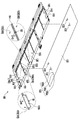
도 1은 본 발명의 일 실시예의 전지 모듈의 사시도이다.
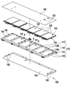
도 2는 도 1의 전지 모듈의 분해 사시도이다.
도 3은 도 2의 전지 모듈을 부분적으로 나타낸 분해 사시도이다.
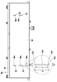
도 4는 도 1의 전지 모듈의 평면도이다. 1 is a perspective view of a battery module according to an embodiment of the present invention.
2 is an exploded perspective view of the battery module of FIG. 1.
3 is an exploded perspective view partially showing the battery module of FIG. 2.
4 is a plan view of the battery module of FIG. 1.
본 발명의 상기 특징 및 장점을 더욱 뚜렷하고 알기 쉽도록 하기 위하여 이하 실시예 및 첨부된 도면을 참조하여 하기와 같이 상세히 설명한다.In order to make the above features and advantages of the present invention more clear and easy to understand, it will be described in detail as follows with reference to the following examples and the accompanying drawings.
도 1은 본 발명의 일 실시예의 전지 모듈의 사시도이다. 도 2는 도 1의 전지 모듈의 분해 사시도이다. 도 3은 도 2의 전지 모듈을 부분적으로 나타낸 분해 사시도이다. 도 4는 도 1의 전지 모듈의 평면도이다. 설명하기 쉽도록, 도 3에서 라벨층(130)은 프레임(110)의 윗측에 나타내었고, 전지 셀(120) 및 커버층(140)은 프레임(110) 상에 조립되어 있는 상태를 나타내었다. 1 is a perspective view of a battery module according to an embodiment of the present invention. 2 is an exploded perspective view of the battery module of FIG. 1. 3 is an exploded perspective view partially showing the battery module of FIG. 2. 4 is a plan view of the battery module of FIG. 1. For ease of explanation, in FIG. 3, the
도1, 도 2, 도 3 및 도 4를 참조하면, 본 실시예에서, 전지 모듈(100)은 프레임(110), 복수개의 전지 셀(120) 및 라벨층(130)을 포함한다. 프레임(110)은 프레임 본체(112), 복수개의 제1 격판(114) 및 적어도 하나의 제2 격판(116)을 포함한다. 제1 격판(114)과 제2 격판(116)은 프레임 본체(112) 내에 위치하고 프레임 본체(112)에 연결되며, 프레임 본체(112)를 복수개의 수용 구역(A)으로 나눈다. 제2 격판(116)은 격판부(116a)와 격판부(116a)에 연결되는 적어도 하나의 지지부(116b)를 포함한다. 여기서, 도 2에서와 같이, 제2 격판(116)의 높이는 제1 격판(114)의 높이보다 높고, 제1 격판(114)의 높이는 제2 격판(116)의 격판부(116a) 높이와 서로 비슷하다. 1, 2, 3, and 4, in this embodiment, the
전지 셀(120)은 프레임(110)의 프레임 본체(112)에 고정되고 수용 구역(A) 내에 각각 위치한다. 여기서, 전지 셀(120)은 예를 들면 파우치 셀(Pouch cell)혹은 각형 셀(Prismatic cell)이지만, 이에 제한되지 않는다. 매 전지 셀(120)은 서로 대향되는 제1 표면(122)과 제2 표면(124)을 구비한다. 지지부(116b)의 제1 윗면(S1)과 매 전지 셀(120)의 제1 표면(122)은 제1 높이차(H1)를 가진다. 제1 격판(114)의 제2 윗면(S2)과 매 전지 셀(120)의 제1 표면(122)은 제2 높이차(H2)를 가진다. 바람직하게, 제1 높이차(H1)는 제2 높이차(H2)보다 크다. The
특히, 본 실시예의 라벨층(130)은 프레임(110) 위에 설치되고 적어도 하나의 절단선 패턴(132)을 가진다, 제2 격판(116)의 지지부(116b)는 절단선 패턴(132)을 통과하고, 라벨층(130)은 전지 셀(120)의 제1 표면(122)을 완전히 피복한다. 더욱 구체적으로, 본 실시예의 절단선 패턴(132)은 제1 절단선(132a), 제2 절단선(132b) 및 제3 절단선(132c)을 포함한다. 제2 절단선(132b)과 제1 절단선(132a)은 평행하고, 제3 절단선(132c)은 제1 절단선(132a)과 제2 절단선(132b)에 수직으로 연결된다. 여기서, 제1 절단선(132a)의 길이(L1)는 제2 절단선(132b)의 길이(L2)와 같고, 제3 절단선(132c)의 길이(L3)는 제1 절단선(132a)의 길이(L1)보다 크며, 절단선 패턴(132)은 예를 들면 "工"자형이다. 제3 절단선(132c)의 길이(L3)는 지지부(116b)의 길이(L)에 2mm를 더한 길이와 같다. 도 1에서와 같이, 제2 격판(116)의 지지부(116b)는 제3 절단선(132c)을 통과하여, 라벨층(130)은 매 전지 셀(120)의 제1 표면(122)을 완전히 피복한다. In particular, the
바람직하게, 제2 격판(116)의 지지부(116b)의 높이(H)와 제1 절단선(132a)의 일단(133)에서 제3 절단선(132c)까지의 수평거리(W)의 비는 3 : 2이다. 이러한 비율에 의해, 제2 격판(116)의 지지부(116b)는 라벨층(130)을 파괴하지 않으면서(예를 들면 라벨층이 찢겨져 갈라지지 않으면서)절단선 패턴(132)을 통과할 수 있으며, 라벨층(130)은 지지부(116b)의 주변을 따라 전지 셀(120)을 피복한다. 기존의 홀을 구비하는 라벨층에서, 홀의 면적이 돌출 리브의 면적보다 크며, 돌출 리브가 라벨층을 통과하여 라벨층이 전지 셀에 피복될 때 전지 셀의 부분적 표면이 노출되게 된다. 하지만, 본 실시예의 라벨층(130)은 절단선 패턴(132)을 구비하며, 이 중 절단선 패턴(132)의 선폭은 제2 격판(116)의 지지부(116b)의 면적에 비해 훨씬 작다. 따라서, 제2 격판(116)의 지지부(116b)가 절단선 패턴(132)을 통과할 때, 라벨층(130)은 매 전지 셀(120)의 제1 표면(122)을 완전히 피복한다. 즉, 라벨층(130)의 절단선 패턴(132)은 전지 셀(120)의 제1 표면(122)을 노출시키지 않는다. Preferably, the ratio of the height (H) of the
또한, 본 실시예의 전지 모듈(100)은 커버층(140)을 더 포함하며, 커버층(140)의 재질은 라벨층(130)의 재질과 같거나 다를 수 있으며 이에 제한되지 않는다. 프레임(110)은 커버층(140)과 라벨층(130) 사이에 위치하며, 이 중 커버층(140)은 전지 셀(120)의 제1 표면(122)에 대해 제2 표면(124)을 피복한다. 즉, 전지 셀(120)의 제1 표면(122)과 제2 표면(124)은 각각 라벨층(130)과 커버층(140)에 의해 완전히 피복된다. 본 실시예에서 커버층(140)은 복수개의 제1 조립부(142)를 포함하며, 프레임(110)은 복수개의 제2 조립부(118)를 포함한다. 제1 조립부(142)는 각각 제2 조립부(118)에 조립되고, 커버층(140)은 프레임(110)에 고정된다. 제1 조립부(142)와 제2 조립부(118) 중의 하나는 슬롯이고, 제1 조립부(142)와 제2 조립부(118) 중 다른 하나는 후크이다. 여기서, 제1 조립부(142)는 후크로 구현되고, 제2 조립부(118)는 슬롯으로 구현될 수 있으나, 이에 제한되지 않는다. In addition, the
즉, 본 실시예의 전지 모듈(100)의 설계에서, 제2 격판(116)의 지지부(116b)는 라벨층(130)의 절단선 패턴(132)을 통과하며, 라벨층(130)은 전지 셀(120)의 제1 표면(122)을 완전히 피복하여 노출되는 것을 방지한다. 따라서, 기존의 홀을 구비하는 라벨층에 비해, 본 실시예의 전지 모듈(100)은 따로 블랙 테이프를 사용할 필요가 없고 효과적으로 조립 과정을 간소화할 수 있으며 생산 코스트를 절감할 수 있다. That is, in the design of the
상술한 바와 같이, 본 발명의 전지 모듈의 설계에서, 라벨층은 절단선 패턴을 구비하고, 제2 격판의 지지부는 절단선 패턴을 통과하며, 라벨층이 전지 셀의 제1 표면을 완전히 피복한다. 기존의 홀을 구비하는 라벨층에 비해, 본 발명의 라벨층의 절단선 패턴은 프레임 내의 전지 셀이 노출되는 것을 방지하여 따로 블랙 테이프를 사용할 필요가 없다. 이에, 본 발명의 전지 모듈은 효과적으로 그 조립 과정을 간소화할 수 있으며 생산 코스트를 절감할 수 있다. As described above, in the design of the battery module of the present invention, the label layer has a cut line pattern, the support portion of the second diaphragm passes through the cut line pattern, and the label layer completely covers the first surface of the battery cell. . Compared to the conventional label layer having holes, the cutting line pattern of the label layer of the present invention prevents the battery cells in the frame from being exposed, so that there is no need to use a separate black tape. Accordingly, the battery module of the present invention can effectively simplify the assembly process and reduce production cost.
실시예에 의해 본 발명을 설명하였는데 본 발명은 이에 한정되는 것이 아니며 임의의 기술분야의 기술자들은 본 발명의 사상 범위를 벗어나지 않는 전제하에 적당한 변경과 수정을 할 수 있으며 이는 모두 본 발명의 보호 범위 내에 속하며 본 발명은 청구범위를 기준으로 한다. The present invention has been described by examples, but the present invention is not limited thereto, and those skilled in the art can make appropriate changes and modifications without departing from the spirit scope of the present invention, which are all within the protection scope of the present invention. And the invention is based on the claims.
100:전지 모듈
110:프레임
112:프레임 본체
114:제1 격판
116:제2 격판
116a:격판부
116b:지지부
118:제2 조립부
120:전지 셀
122:제1 표면
124:제2 표면
130:라벨층
132:절단선 패턴
132a:제1 절단선
132b:제2 절단선
132c:제3 절단선
133:일단
140:커버층
142:제1 조립부
A:수용 구역
H:높이
H1:제1 높이차
H2:제2 높이차
L, L1, L2, L3:길이
S1:제1 윗면
S2:제2 윗면
W:수평거리 100: battery module 110: frame
112: frame body 114: first diaphragm
116:
116b: Support 118: Second assembly
120: battery cell 122: first surface
124: second surface 130: label layer
132: cutting
132b: second cutting
133: first 140: cover layer
142:1st assembly part A:reception area
H: Height H1: First height difference
H2: 2nd height difference L, L1, L2, L3: length
S1:
W:Horizontal distance
Claims (10)
상기 프레임은 프레임 본체, 복수개의 제1 격판 및 적어도 하나의 제2 격판을 포함하며, 상기 제1 격판과 상기 제2 격판은 상기 프레임 본체 내에 위치하고 상기 프레임 본체에 연결되며 상기 프레임 본체를 복수개의 수용 구역으로 나누며, 이 중 상기 제2 격판은 격판부와 상기 격판부에 연결되는 적어도 하나의 지지부를 포함하며;
상기 복수개의 전지 셀은 상기 프레임 본체 상에 고정되고, 각각 상기 수용 구역 내에 위치하며, 각 상기 전지 셀은 제1 표면을 구비하고, 상기 지지부의 제1 윗면과 각 상기 전지 셀의 상기 제1 표면은 제1 높이차를 가지고, 각 상기 제1 격판의 제2 윗면과 각 상기 전지 셀의 상기 제1 표면은 제2 높이차를 가지며, 상기 제1 높이차는 제2 높이차보다 크고;
상기 라벨층은 상기 프레임 위에 설치되며, 적어도 하나의 절단선 패턴을 구비하고, 상기 지지부는 상기 절단선 패턴을 통과하며, 상기 라벨층은 각 상기 전지 셀의 상기 제1 표면을 완전히 피복하는 것을 특징으로 하는 전지 모듈.A battery module comprising a frame, a plurality of battery cells, and a label layer,
The frame includes a frame body, a plurality of first diaphragms, and at least one second diaphragm, the first diaphragm and the second diaphragm are located in the frame body and connected to the frame body, and accommodate a plurality of the frame body It is divided into zones, of which the second diaphragm includes a diaphragm and at least one supporting part connected to the diaphragm;
The plurality of battery cells are fixed on the frame body, each located in the receiving area, each of the battery cells having a first surface, a first upper surface of the support portion and the first surface of each of the battery cells Has a first height difference, the second upper surface of each of the first diaphragms and the first surface of each of the battery cells have a second height difference, and the first height difference is greater than the second height difference;
The label layer is installed on the frame, has at least one cutting line pattern, the support part passes through the cutting line pattern, and the label layer completely covers the first surface of each of the battery cells. Battery module.
상기 절단선 패턴은 제1 절단선, 제2 절단선 및 제3 절단선을 포함하며,
상기 제2 절단선은 상기 제1 절단선에 평행하고,
상기 제3 절단선은 상기 제1 절단선과 상기 제2 절단선에 수직으로 연결되며, 상기 지지부는 상기 제3 절단선을 통과하여 상기 라벨층으로 하여금 각 상기 전지 셀의 상기 제1 표면을 완전히 피복하도록 하는 것을 특징으로 하는 전지 모듈.The method of claim 1,
The cutting line pattern includes a first cutting line, a second cutting line, and a third cutting line,
The second cutting line is parallel to the first cutting line,
The third cutting line is connected perpendicularly to the first cutting line and the second cutting line, and the support part passes through the third cutting line so that the label layer completely covers the first surface of each of the battery cells. Battery module, characterized in that to.
상기 제1 절단선의 길이는 상기 제2 절단선의 길이와 같으며, 상기 제3 절단선의 길이는 상기 제1 절단선의 길이보다 큰 것을 특징으로 하는 전지 모듈.The method of claim 2,
The length of the first cutting line is the same as the length of the second cutting line, and the length of the third cutting line is greater than the length of the first cutting line.
상기 절단선 패턴은 "工”자형인 것을 특징으로 하는 전지 모듈.The method of claim 3,
The battery module, characterized in that the cut line pattern has a "工" shape.
상기 지지부의 높이와 상기 제1 절단선의 일단에서 상기 제3 절단선까지의 수평거리의 비는 3 : 2인 것을 특징으로 하는 전지 모듈.The method of claim 4,
The battery module, characterized in that the ratio of the height of the support and the horizontal distance from one end of the first cutting line to the third cutting line is 3:2.
상기 제3 절단선의 길이는 상기 지지부의 길이에 2mm를 더한 길이와 같은 것을 특징으로 하는 전지 모듈.The method of claim 4,
A battery module, characterized in that the length of the third cutting line is equal to the length of the support portion plus 2 mm.
상기 전지 모듈은 커버층을 더 포함하며, 상기 프레임은 상기 커버층과 상기 라벨층 사이에 위치하고, 상기 커버층은 각 상기 전지 셀의 상기 제1 표면에 대해 제2 표면을 피복하는 것을 특징으로 하는 전지 모듈.The method of claim 1,
The battery module further includes a cover layer, wherein the frame is positioned between the cover layer and the label layer, and the cover layer covers a second surface with respect to the first surface of each of the battery cells. Battery module.
상기 커버층은 복수개의 제1 조립부를 포함하고, 상기 프레임은 복수개의 제2 조립부를 구비하며, 상기 제1 조립부들은 각각 상기 제2 조립부에 조립되고, 상기 커버층은 상기 프레임에 고정되는 것을 특징으로 하는 전지 모듈.The method of claim 7,
The cover layer includes a plurality of first assembly portions, the frame has a plurality of second assembly portions, the first assembly portions are each assembled to the second assembly portion, and the cover layer is fixed to the frame. A battery module, characterized in that.
상기 제1 조립부와 상기 제2 조립부 중 하나는 슬롯이고, 상기 제1 조립부와 상기 제2 조립부 중 다른 하나는 후크인 것을 특징으로 하는 전지 모듈.The method of claim 8,
One of the first assembly portion and the second assembly portion is a slot, and the other of the first assembly portion and the second assembly portion is a hook.
상기 전지 셀들은 각각 파우치 셀 혹은 각형 셀인 것을 특징으로 하는 전지 모듈. The method of claim 1,
Each of the battery cells is a pouch cell or a prismatic cell.
Priority Applications (1)
| Application Number | Priority Date | Filing Date | Title |
|---|---|---|---|
| KR1020190013770A KR102656440B1 (en) | 2019-02-01 | 2019-02-01 | Battery module |
Applications Claiming Priority (1)
| Application Number | Priority Date | Filing Date | Title |
|---|---|---|---|
| KR1020190013770A KR102656440B1 (en) | 2019-02-01 | 2019-02-01 | Battery module |
Publications (2)
| Publication Number | Publication Date |
|---|---|
| KR20200096362A true KR20200096362A (en) | 2020-08-12 |
| KR102656440B1 KR102656440B1 (en) | 2024-04-09 |
Family
ID=72039235
Family Applications (1)
| Application Number | Title | Priority Date | Filing Date |
|---|---|---|---|
| KR1020190013770A Active KR102656440B1 (en) | 2019-02-01 | 2019-02-01 | Battery module |
Country Status (1)
| Country | Link |
|---|---|
| KR (1) | KR102656440B1 (en) |
Cited By (1)
| Publication number | Priority date | Publication date | Assignee | Title |
|---|---|---|---|---|
| JP2025501841A (en) * | 2022-12-14 | 2025-01-24 | エルジー エナジー ソリューション リミテッド | Battery Device |
Citations (3)
| Publication number | Priority date | Publication date | Assignee | Title |
|---|---|---|---|---|
| KR20110089679A (en) * | 2010-02-01 | 2011-08-09 | 주식회사 엘지화학 | Battery cell assembly having a novel structure and a battery pack comprising the same |
| KR101416544B1 (en) * | 2013-08-02 | 2014-07-09 | (주)대원산업 | Rechargeable Battery Case |
| KR101520391B1 (en) * | 2014-02-11 | 2015-05-14 | 삼성에스디아이 주식회사 | Battery Pack |
-
2019
- 2019-02-01 KR KR1020190013770A patent/KR102656440B1/en active Active
Patent Citations (3)
| Publication number | Priority date | Publication date | Assignee | Title |
|---|---|---|---|---|
| KR20110089679A (en) * | 2010-02-01 | 2011-08-09 | 주식회사 엘지화학 | Battery cell assembly having a novel structure and a battery pack comprising the same |
| KR101416544B1 (en) * | 2013-08-02 | 2014-07-09 | (주)대원산업 | Rechargeable Battery Case |
| KR101520391B1 (en) * | 2014-02-11 | 2015-05-14 | 삼성에스디아이 주식회사 | Battery Pack |
Cited By (1)
| Publication number | Priority date | Publication date | Assignee | Title |
|---|---|---|---|---|
| JP2025501841A (en) * | 2022-12-14 | 2025-01-24 | エルジー エナジー ソリューション リミテッド | Battery Device |
Also Published As
| Publication number | Publication date |
|---|---|
| KR102656440B1 (en) | 2024-04-09 |
Similar Documents
| Publication | Publication Date | Title |
|---|---|---|
| KR102549509B1 (en) | Secondary battery, battery module, battery pack, device and manufacturing method thereof | |
| KR102065098B1 (en) | Secondary battery module improved in frame structure and frame assembly for the same | |
| US6294288B1 (en) | Battery cell having notched layers | |
| EP3084859B1 (en) | Housing assembly and battery module comprising the same | |
| KR100902691B1 (en) | Battery pack | |
| EP3352244A1 (en) | Battery module comprising end plates having improved strucutre, and end plate member therefor | |
| EP4407770B1 (en) | Battery pack | |
| US20110305938A1 (en) | Electrode layered product for cell and method for making the same | |
| US10547031B2 (en) | Protection tape and secondary battery having the same | |
| EP3591733B1 (en) | Cover assembly and battery module including the same | |
| US10700319B2 (en) | Battery module including strap-type frame, and frame assembly therefor | |
| CN115621654B (en) | Electronic equipment | |
| KR20200096362A (en) | Battery module | |
| KR20220141606A (en) | Battery module and battery pack including the same | |
| CN217062428U (en) | Converging sheet structure and cylindrical battery | |
| JP2002124233A (en) | Battery pack | |
| JP6651882B2 (en) | Lead storage battery | |
| TWI759581B (en) | Battery module | |
| CN112909394B (en) | battery pack | |
| JP3625734B2 (en) | Pack battery | |
| JP5419150B2 (en) | Battery packaging | |
| CN220042191U (en) | Conductive bar, battery module, battery pack and electric equipment | |
| CN222915003U (en) | Battery bottom guard plate and battery having the same | |
| CN219779113U (en) | Battery box and energy storage system | |
| CN216720044U (en) | Battery capacity grading tray |
Legal Events
| Date | Code | Title | Description |
|---|---|---|---|
| PA0109 | Patent application |
Patent event code: PA01091R01D Comment text: Patent Application Patent event date: 20190201 |
|
| PG1501 | Laying open of application | ||
| N231 | Notification of change of applicant | ||
| PN2301 | Change of applicant |
Patent event date: 20210512 Comment text: Notification of Change of Applicant Patent event code: PN23011R01D |
|
| E902 | Notification of reason for refusal | ||
| PE0902 | Notice of grounds for rejection |
Comment text: Notification of reason for refusal Patent event date: 20240315 Patent event code: PE09021S01D |
|
| E701 | Decision to grant or registration of patent right | ||
| PE0701 | Decision of registration |
Patent event code: PE07011S01D Comment text: Decision to Grant Registration Patent event date: 20240401 |
|
| GRNT | Written decision to grant | ||
| PR0701 | Registration of establishment |
Comment text: Registration of Establishment Patent event date: 20240405 Patent event code: PR07011E01D |
|
| PR1002 | Payment of registration fee |
Payment date: 20240405 End annual number: 3 Start annual number: 1 |
|
| PG1601 | Publication of registration |