KR20200097802A - Continuous blood pressure measurement - Google Patents
Continuous blood pressure measurement Download PDFInfo
- Publication number
- KR20200097802A KR20200097802A KR1020207021477A KR20207021477A KR20200097802A KR 20200097802 A KR20200097802 A KR 20200097802A KR 1020207021477 A KR1020207021477 A KR 1020207021477A KR 20207021477 A KR20207021477 A KR 20207021477A KR 20200097802 A KR20200097802 A KR 20200097802A
- Authority
- KR
- South Korea
- Prior art keywords
- values
- processing system
- tracking
- calibration
- data
- Prior art date
- Legal status (The legal status is an assumption and is not a legal conclusion. Google has not performed a legal analysis and makes no representation as to the accuracy of the status listed.)
- Ceased
Links
- 238000009530 blood pressure measurement Methods 0.000 title description 7
- 238000000034 method Methods 0.000 claims abstract description 53
- 230000000004 hemodynamic effect Effects 0.000 claims abstract description 29
- 238000012545 processing Methods 0.000 claims description 199
- 230000006870 function Effects 0.000 claims description 88
- 230000004872 arterial blood pressure Effects 0.000 abstract description 44
- 230000000747 cardiac effect Effects 0.000 description 65
- 230000035485 pulse pressure Effects 0.000 description 63
- 230000000875 corresponding effect Effects 0.000 description 43
- 230000036772 blood pressure Effects 0.000 description 23
- 238000005259 measurement Methods 0.000 description 22
- 230000002526 effect on cardiovascular system Effects 0.000 description 17
- 238000010586 diagram Methods 0.000 description 13
- 238000010606 normalization Methods 0.000 description 13
- 239000011159 matrix material Substances 0.000 description 12
- 239000003990 capacitor Substances 0.000 description 11
- 238000013186 photoplethysmography Methods 0.000 description 9
- 230000017531 blood circulation Effects 0.000 description 8
- 230000036962 time dependent Effects 0.000 description 8
- 238000012546 transfer Methods 0.000 description 8
- 239000013598 vector Substances 0.000 description 8
- 230000005540 biological transmission Effects 0.000 description 7
- 239000008280 blood Substances 0.000 description 7
- 210000004369 blood Anatomy 0.000 description 7
- 210000000748 cardiovascular system Anatomy 0.000 description 7
- 230000002596 correlated effect Effects 0.000 description 7
- 238000005070 sampling Methods 0.000 description 7
- 210000001367 artery Anatomy 0.000 description 6
- 230000004044 response Effects 0.000 description 6
- 230000001419 dependent effect Effects 0.000 description 5
- 238000013461 design Methods 0.000 description 5
- 101000979001 Homo sapiens Methionine aminopeptidase 2 Proteins 0.000 description 4
- 101000969087 Homo sapiens Microtubule-associated protein 2 Proteins 0.000 description 4
- 102100021118 Microtubule-associated protein 2 Human genes 0.000 description 4
- 230000003205 diastolic effect Effects 0.000 description 4
- 239000003550 marker Substances 0.000 description 4
- 101000969594 Homo sapiens Modulator of apoptosis 1 Proteins 0.000 description 3
- 102100021440 Modulator of apoptosis 1 Human genes 0.000 description 3
- QVGXLLKOCUKJST-UHFFFAOYSA-N atomic oxygen Chemical compound [O] QVGXLLKOCUKJST-UHFFFAOYSA-N 0.000 description 3
- 230000007175 bidirectional communication Effects 0.000 description 3
- 230000006854 communication Effects 0.000 description 3
- 238000004891 communication Methods 0.000 description 3
- 210000003414 extremity Anatomy 0.000 description 3
- 230000004217 heart function Effects 0.000 description 3
- 210000000056 organ Anatomy 0.000 description 3
- 229910052760 oxygen Inorganic materials 0.000 description 3
- 239000001301 oxygen Substances 0.000 description 3
- 238000001228 spectrum Methods 0.000 description 3
- 230000000007 visual effect Effects 0.000 description 3
- 206010005746 Blood pressure fluctuation Diseases 0.000 description 2
- 241000701922 Bovine parvovirus Species 0.000 description 2
- 230000035487 diastolic blood pressure Effects 0.000 description 2
- 210000000624 ear auricle Anatomy 0.000 description 2
- 230000000694 effects Effects 0.000 description 2
- 210000001061 forehead Anatomy 0.000 description 2
- 210000003128 head Anatomy 0.000 description 2
- 238000005457 optimization Methods 0.000 description 2
- 238000005086 pumping Methods 0.000 description 2
- 230000035488 systolic blood pressure Effects 0.000 description 2
- 210000000707 wrist Anatomy 0.000 description 2
- 241000282412 Homo Species 0.000 description 1
- 241000124008 Mammalia Species 0.000 description 1
- OAICVXFJPJFONN-UHFFFAOYSA-N Phosphorus Chemical compound [P] OAICVXFJPJFONN-UHFFFAOYSA-N 0.000 description 1
- 238000010521 absorption reaction Methods 0.000 description 1
- 210000000709 aorta Anatomy 0.000 description 1
- 238000010009 beating Methods 0.000 description 1
- 230000006399 behavior Effects 0.000 description 1
- 210000004204 blood vessel Anatomy 0.000 description 1
- 210000005242 cardiac chamber Anatomy 0.000 description 1
- 238000007675 cardiac surgery Methods 0.000 description 1
- 230000008602 contraction Effects 0.000 description 1
- 238000000354 decomposition reaction Methods 0.000 description 1
- 230000006735 deficit Effects 0.000 description 1
- 230000001934 delay Effects 0.000 description 1
- 239000006185 dispersion Substances 0.000 description 1
- 230000005611 electricity Effects 0.000 description 1
- 230000003203 everyday effect Effects 0.000 description 1
- 230000005284 excitation Effects 0.000 description 1
- 239000012530 fluid Substances 0.000 description 1
- 230000031700 light absorption Effects 0.000 description 1
- 238000012544 monitoring process Methods 0.000 description 1
- 230000003287 optical effect Effects 0.000 description 1
- 239000013307 optical fiber Substances 0.000 description 1
- 230000010412 perfusion Effects 0.000 description 1
- 229910052698 phosphorus Inorganic materials 0.000 description 1
- 239000011574 phosphorus Substances 0.000 description 1
- 230000003252 repetitive effect Effects 0.000 description 1
- 239000004065 semiconductor Substances 0.000 description 1
- 230000002123 temporal effect Effects 0.000 description 1
Images







Classifications
-
- A—HUMAN NECESSITIES
- A61—MEDICAL OR VETERINARY SCIENCE; HYGIENE
- A61B—DIAGNOSIS; SURGERY; IDENTIFICATION
- A61B5/00—Measuring for diagnostic purposes; Identification of persons
- A61B5/02—Detecting, measuring or recording for evaluating the cardiovascular system, e.g. pulse, heart rate, blood pressure or blood flow
-
- A—HUMAN NECESSITIES
- A61—MEDICAL OR VETERINARY SCIENCE; HYGIENE
- A61B—DIAGNOSIS; SURGERY; IDENTIFICATION
- A61B5/00—Measuring for diagnostic purposes; Identification of persons
- A61B5/02—Detecting, measuring or recording for evaluating the cardiovascular system, e.g. pulse, heart rate, blood pressure or blood flow
- A61B5/021—Measuring pressure in heart or blood vessels
- A61B5/022—Measuring pressure in heart or blood vessels by applying pressure to close blood vessels, e.g. against the skin; Ophthalmodynamometers
- A61B5/02225—Measuring pressure in heart or blood vessels by applying pressure to close blood vessels, e.g. against the skin; Ophthalmodynamometers using the oscillometric method
-
- A—HUMAN NECESSITIES
- A61—MEDICAL OR VETERINARY SCIENCE; HYGIENE
- A61B—DIAGNOSIS; SURGERY; IDENTIFICATION
- A61B5/00—Measuring for diagnostic purposes; Identification of persons
- A61B5/0002—Remote monitoring of patients using telemetry, e.g. transmission of vital signals via a communication network
- A61B5/0004—Remote monitoring of patients using telemetry, e.g. transmission of vital signals via a communication network characterised by the type of physiological signal transmitted
-
- A—HUMAN NECESSITIES
- A61—MEDICAL OR VETERINARY SCIENCE; HYGIENE
- A61B—DIAGNOSIS; SURGERY; IDENTIFICATION
- A61B5/00—Measuring for diagnostic purposes; Identification of persons
- A61B5/02—Detecting, measuring or recording for evaluating the cardiovascular system, e.g. pulse, heart rate, blood pressure or blood flow
- A61B5/02028—Determining haemodynamic parameters not otherwise provided for, e.g. cardiac contractility or left ventricular ejection fraction
-
- A—HUMAN NECESSITIES
- A61—MEDICAL OR VETERINARY SCIENCE; HYGIENE
- A61B—DIAGNOSIS; SURGERY; IDENTIFICATION
- A61B5/00—Measuring for diagnostic purposes; Identification of persons
- A61B5/02—Detecting, measuring or recording for evaluating the cardiovascular system, e.g. pulse, heart rate, blood pressure or blood flow
- A61B5/021—Measuring pressure in heart or blood vessels
-
- A—HUMAN NECESSITIES
- A61—MEDICAL OR VETERINARY SCIENCE; HYGIENE
- A61B—DIAGNOSIS; SURGERY; IDENTIFICATION
- A61B5/00—Measuring for diagnostic purposes; Identification of persons
- A61B5/02—Detecting, measuring or recording for evaluating the cardiovascular system, e.g. pulse, heart rate, blood pressure or blood flow
- A61B5/021—Measuring pressure in heart or blood vessels
- A61B5/02108—Measuring pressure in heart or blood vessels from analysis of pulse wave characteristics
-
- A—HUMAN NECESSITIES
- A61—MEDICAL OR VETERINARY SCIENCE; HYGIENE
- A61B—DIAGNOSIS; SURGERY; IDENTIFICATION
- A61B5/00—Measuring for diagnostic purposes; Identification of persons
- A61B5/02—Detecting, measuring or recording for evaluating the cardiovascular system, e.g. pulse, heart rate, blood pressure or blood flow
- A61B5/021—Measuring pressure in heart or blood vessels
- A61B5/022—Measuring pressure in heart or blood vessels by applying pressure to close blood vessels, e.g. against the skin; Ophthalmodynamometers
-
- A—HUMAN NECESSITIES
- A61—MEDICAL OR VETERINARY SCIENCE; HYGIENE
- A61B—DIAGNOSIS; SURGERY; IDENTIFICATION
- A61B5/00—Measuring for diagnostic purposes; Identification of persons
- A61B5/02—Detecting, measuring or recording for evaluating the cardiovascular system, e.g. pulse, heart rate, blood pressure or blood flow
- A61B5/024—Measuring pulse rate or heart rate
- A61B5/02416—Measuring pulse rate or heart rate using photoplethysmograph signals, e.g. generated by infrared radiation
- A61B5/02427—Details of sensor
-
- A—HUMAN NECESSITIES
- A61—MEDICAL OR VETERINARY SCIENCE; HYGIENE
- A61B—DIAGNOSIS; SURGERY; IDENTIFICATION
- A61B5/00—Measuring for diagnostic purposes; Identification of persons
- A61B5/02—Detecting, measuring or recording for evaluating the cardiovascular system, e.g. pulse, heart rate, blood pressure or blood flow
- A61B5/024—Measuring pulse rate or heart rate
- A61B5/02444—Details of sensor
-
- A—HUMAN NECESSITIES
- A61—MEDICAL OR VETERINARY SCIENCE; HYGIENE
- A61B—DIAGNOSIS; SURGERY; IDENTIFICATION
- A61B5/00—Measuring for diagnostic purposes; Identification of persons
- A61B5/145—Measuring characteristics of blood in vivo, e.g. gas concentration or pH-value ; Measuring characteristics of body fluids or tissues, e.g. interstitial fluid or cerebral tissue
- A61B5/1455—Measuring characteristics of blood in vivo, e.g. gas concentration or pH-value ; Measuring characteristics of body fluids or tissues, e.g. interstitial fluid or cerebral tissue using optical sensors, e.g. spectral photometrical oximeters
- A61B5/14551—Measuring characteristics of blood in vivo, e.g. gas concentration or pH-value ; Measuring characteristics of body fluids or tissues, e.g. interstitial fluid or cerebral tissue using optical sensors, e.g. spectral photometrical oximeters for measuring blood gases
-
- A—HUMAN NECESSITIES
- A61—MEDICAL OR VETERINARY SCIENCE; HYGIENE
- A61B—DIAGNOSIS; SURGERY; IDENTIFICATION
- A61B5/00—Measuring for diagnostic purposes; Identification of persons
- A61B5/68—Arrangements of detecting, measuring or recording means, e.g. sensors, in relation to patient
- A61B5/6801—Arrangements of detecting, measuring or recording means, e.g. sensors, in relation to patient specially adapted to be attached to or worn on the body surface
- A61B5/6813—Specially adapted to be attached to a specific body part
- A61B5/6824—Arm or wrist
-
- A—HUMAN NECESSITIES
- A61—MEDICAL OR VETERINARY SCIENCE; HYGIENE
- A61B—DIAGNOSIS; SURGERY; IDENTIFICATION
- A61B5/00—Measuring for diagnostic purposes; Identification of persons
- A61B5/68—Arrangements of detecting, measuring or recording means, e.g. sensors, in relation to patient
- A61B5/6801—Arrangements of detecting, measuring or recording means, e.g. sensors, in relation to patient specially adapted to be attached to or worn on the body surface
- A61B5/6813—Specially adapted to be attached to a specific body part
- A61B5/6825—Hand
- A61B5/6826—Finger
-
- A—HUMAN NECESSITIES
- A61—MEDICAL OR VETERINARY SCIENCE; HYGIENE
- A61B—DIAGNOSIS; SURGERY; IDENTIFICATION
- A61B5/00—Measuring for diagnostic purposes; Identification of persons
- A61B5/68—Arrangements of detecting, measuring or recording means, e.g. sensors, in relation to patient
- A61B5/6801—Arrangements of detecting, measuring or recording means, e.g. sensors, in relation to patient specially adapted to be attached to or worn on the body surface
- A61B5/6843—Monitoring or controlling sensor contact pressure
-
- A—HUMAN NECESSITIES
- A61—MEDICAL OR VETERINARY SCIENCE; HYGIENE
- A61B—DIAGNOSIS; SURGERY; IDENTIFICATION
- A61B5/00—Measuring for diagnostic purposes; Identification of persons
- A61B5/72—Signal processing specially adapted for physiological signals or for diagnostic purposes
-
- A—HUMAN NECESSITIES
- A61—MEDICAL OR VETERINARY SCIENCE; HYGIENE
- A61B—DIAGNOSIS; SURGERY; IDENTIFICATION
- A61B5/00—Measuring for diagnostic purposes; Identification of persons
- A61B5/72—Signal processing specially adapted for physiological signals or for diagnostic purposes
- A61B5/7225—Details of analogue processing, e.g. isolation amplifier, gain or sensitivity adjustment, filtering, baseline or drift compensation
-
- A—HUMAN NECESSITIES
- A61—MEDICAL OR VETERINARY SCIENCE; HYGIENE
- A61B—DIAGNOSIS; SURGERY; IDENTIFICATION
- A61B5/00—Measuring for diagnostic purposes; Identification of persons
- A61B5/72—Signal processing specially adapted for physiological signals or for diagnostic purposes
- A61B5/7235—Details of waveform analysis
-
- A—HUMAN NECESSITIES
- A61—MEDICAL OR VETERINARY SCIENCE; HYGIENE
- A61B—DIAGNOSIS; SURGERY; IDENTIFICATION
- A61B5/00—Measuring for diagnostic purposes; Identification of persons
- A61B5/72—Signal processing specially adapted for physiological signals or for diagnostic purposes
- A61B5/7235—Details of waveform analysis
- A61B5/7253—Details of waveform analysis characterised by using transforms
- A61B5/7257—Details of waveform analysis characterised by using transforms using Fourier transforms
-
- A—HUMAN NECESSITIES
- A61—MEDICAL OR VETERINARY SCIENCE; HYGIENE
- A61B—DIAGNOSIS; SURGERY; IDENTIFICATION
- A61B5/00—Measuring for diagnostic purposes; Identification of persons
- A61B5/72—Signal processing specially adapted for physiological signals or for diagnostic purposes
- A61B5/7271—Specific aspects of physiological measurement analysis
- A61B5/7275—Determining trends in physiological measurement data; Predicting development of a medical condition based on physiological measurements, e.g. determining a risk factor
-
- A—HUMAN NECESSITIES
- A61—MEDICAL OR VETERINARY SCIENCE; HYGIENE
- A61B—DIAGNOSIS; SURGERY; IDENTIFICATION
- A61B5/00—Measuring for diagnostic purposes; Identification of persons
- A61B5/74—Details of notification to user or communication with user or patient; User input means
- A61B5/742—Details of notification to user or communication with user or patient; User input means using visual displays
-
- A—HUMAN NECESSITIES
- A61—MEDICAL OR VETERINARY SCIENCE; HYGIENE
- A61B—DIAGNOSIS; SURGERY; IDENTIFICATION
- A61B5/00—Measuring for diagnostic purposes; Identification of persons
- A61B5/74—Details of notification to user or communication with user or patient; User input means
- A61B5/742—Details of notification to user or communication with user or patient; User input means using visual displays
- A61B5/743—Displaying an image simultaneously with additional graphical information, e.g. symbols, charts, function plots
-
- G—PHYSICS
- G16—INFORMATION AND COMMUNICATION TECHNOLOGY [ICT] SPECIALLY ADAPTED FOR SPECIFIC APPLICATION FIELDS
- G16H—HEALTHCARE INFORMATICS, i.e. INFORMATION AND COMMUNICATION TECHNOLOGY [ICT] SPECIALLY ADAPTED FOR THE HANDLING OR PROCESSING OF MEDICAL OR HEALTHCARE DATA
- G16H50/00—ICT specially adapted for medical diagnosis, medical simulation or medical data mining; ICT specially adapted for detecting, monitoring or modelling epidemics or pandemics
- G16H50/50—ICT specially adapted for medical diagnosis, medical simulation or medical data mining; ICT specially adapted for detecting, monitoring or modelling epidemics or pandemics for simulation or modelling of medical disorders
-
- A—HUMAN NECESSITIES
- A61—MEDICAL OR VETERINARY SCIENCE; HYGIENE
- A61B—DIAGNOSIS; SURGERY; IDENTIFICATION
- A61B2560/00—Constructional details of operational features of apparatus; Accessories for medical measuring apparatus
- A61B2560/02—Operational features
- A61B2560/0223—Operational features of calibration, e.g. protocols for calibrating sensors
Landscapes
- Health & Medical Sciences (AREA)
- Life Sciences & Earth Sciences (AREA)
- Engineering & Computer Science (AREA)
- Physics & Mathematics (AREA)
- Public Health (AREA)
- Medical Informatics (AREA)
- Biomedical Technology (AREA)
- General Health & Medical Sciences (AREA)
- Pathology (AREA)
- Animal Behavior & Ethology (AREA)
- Heart & Thoracic Surgery (AREA)
- Molecular Biology (AREA)
- Surgery (AREA)
- Biophysics (AREA)
- Veterinary Medicine (AREA)
- Cardiology (AREA)
- Physiology (AREA)
- Vascular Medicine (AREA)
- Signal Processing (AREA)
- Artificial Intelligence (AREA)
- Psychiatry (AREA)
- Computer Vision & Pattern Recognition (AREA)
- Ophthalmology & Optometry (AREA)
- Mathematical Physics (AREA)
- Spectroscopy & Molecular Physics (AREA)
- Optics & Photonics (AREA)
- Power Engineering (AREA)
- Epidemiology (AREA)
- Nuclear Medicine, Radiotherapy & Molecular Imaging (AREA)
- Radiology & Medical Imaging (AREA)
- Computer Networks & Wireless Communication (AREA)
- Primary Health Care (AREA)
- Databases & Information Systems (AREA)
- Data Mining & Analysis (AREA)
- Measuring Pulse, Heart Rate, Blood Pressure Or Blood Flow (AREA)
Abstract
일 시간 동안 동맥 혈압을 캘리브레이팅하고 다른 시간에 동맥 혈압을 추적함으로써 피험자의 혈역학적 파라미터들의 값들을 추정하기 위한 시스템 및 방법이 개시된다. A system and method are disclosed for estimating values of a subject's hemodynamic parameters by calibrating arterial blood pressure for one hour and tracking arterial blood pressure at different times.
Description
[0001] 배경[0001] Background
[0002] 관련 출원들[0002] Related applications
[0003] "Estimating the relationship between MAP value and pulse amplitude and methods to achieve so"이라는 제목의 미국 가출원 번호 제62/609,435호가 이로써 인용에 의해 본원에 포함된다. [0003] US Provisional Application No. 62/609,435 entitled “Estimating the relationship between MAP value and pulse amplitude and methods to achieve so” is hereby incorporated herein by reference.
[0004] 본 발명의 분야[0004] Field of the present invention
[0005] 본 발명은 인간 BPV(blood pressure value)들의 측정에 관한 것이다.[0005] The present invention relates to the measurement of human blood pressure values (BPV).
[0006] 혈압을 측정하기 위한 혈압계들, 안압계들 및 페나즈(Penaz) 디바이스들은 알려져 있다. 예컨대, 미국 특허들 제5579776호(커프); 제6413223호(안압계); 및 제9,107,588호(페나즈 디바이스)를 참조한다. 혈역학적 파라미터들은 MAP(Mean Arterial Pressure), PP(Pulse Pressure), Ps(Systolic pressure), Pd(Diastolic pressure) 및 SVV(Stroke Volume Variation)를 포함한다. [0006] Blood pressure monitors, tonometers and Penaz devices for measuring blood pressure are known. See, for example, US Pat. Nos. 5 579776 (cuff); No. 6413223 (tonometer); And 9,107,588 (Penas Devices). Hemodynamic parameters include Mean Arterial Pressure (MAP), Pulse Pressure (PP), Systolic pressure (Ps), Diastolic pressure (Pd), and Stroke Volume Variation (SVV).
[0007] 의사는 일반적으로 수동 혈압계 및 청진기를 사용하여 Ps와 Pd를 결정한다. Ps 및 Pd로부터 MAP을 추정하기 위한 관행적 공식은 다음과 같다:[0007] Doctors generally determine Ps and Pd using a manual sphygmomanometer and stethoscope. The conventional formula for estimating MAP from Ps and Pd is as follows:
(1) 
[0008] 오실로메트릭 커프 기반 혈압계들은 이 공식을 사용하지 않고 압력 데이터로부터 직접 MAP, Ps 및 Pd를 결정할 수 있다. Oscillometric cuff based sphygmomanometers can determine MAP, Ps and Pd directly from pressure data without using this formula.
[0009] 심장 주기(cardiac cycle)는 심장이 박동할 때 발생하는 이벤트들의 시퀀스이다. 심장 주기에는 두 페이즈들이 존재한다. 확장기 페이즈에서, 심장 심실들이 이완되고 심장이 혈액으로 채워진다. 수축기 페이즈에서, 심실들은 수축하고 혈액을 심장으로부터 그리고 동맥들로 펌핑한다. 일 심장 주기로부터 발생하는 동맥 혈압 파동들은 수축기와 연관된 제1 세그먼트에 이어지는 확장기와 연관된 제2 페이즈를 포함한다. 제2 페이즈는 통상적으로 중박 노치(dicrotic notch)를 포함하여서, 각각의 심장 주기와 연관된 동맥 혈압 파는 중박 노치의 양 측에 하나씩 최대 2개를 갖는다. [0009] The cardiac cycle is a sequence of events that occur when the heart beats. There are two phases in the cardiac cycle. In the diastolic phase, the heart chambers relax and the heart fills with blood. In the systolic phase, the ventricles constrict and pump blood from the heart and into the arteries. Arterial blood pressure waves arising from one cardiac cycle include a first segment associated with a systolic followed by a second phase associated with a diastolic. The second phase typically includes a dicrotic notch, so that arterial blood pressure waves associated with each cardiac cycle have at most two, one on each side of the dichrotic notch.
[00010] 정의들[00010] Definitions
[00011] 이하에서, "피험자"는 인간 또는 포유 동물을 의미한다. [00011] Hereinafter, "subject" means a human or a mammal.
[00012] 이하에서, "동맥 펄스(arterial pulse)"는 하나의 완전한 심장 주기의 시간에 걸친 혈압 변동과 연관된 신호를 의미한다. Hereinafter, "arterial pulse" means a signal associated with blood pressure fluctuations over time of one complete cardiac cycle.
[00013] 이하에서, "심장 시간 기간(cardiac time period)"은 개별 동맥 펄스에 대응하는 시간 기간을 의미한다. 심장 시간 기간은 이하 본원에서 IBI(InterBeat Interval)로서 또한 지칭된다. Hereinafter, "cardiac time period" means a time period corresponding to individual arterial pulses. The cardiac time period is also referred to herein as InterBeat Interval (IBI).
[00014] 이하, 프로세싱 시스템은 바이오메트릭 트랜스듀서(biometric transducer)들로부터 획득된 신호들을 프로세싱하기 위한 알고리즘들을 구현할 수 있는 시스템을 정의한다. [00014] Hereinafter, the processing system defines a system capable of implementing algorithms for processing signals obtained from biometric transducers.
[00015] 프로세싱 시스템은 프로세싱 유닛 및 메모리를 포함한다. 프로세싱 유닛은 가상화될 수 있으며, 이 경우에, 프로세싱 유닛은 메모리에 컴퓨터 코드로서 저장된다. 따라서, 프로세싱 유닛 및 메모리 둘 모두는 하드웨어를 사용하여 구현된다. 하드웨어는 저항기들, 커패시터들, 인덕터들, 다이오드들, 트랜지스터들, 발광 다이오드들 및 레이저들과 같이 전기 또는 광학 신호들을 변경하는 물리적 컴포넌트들을 지칭한다. 바람직하게는, 프로세싱 시스템은 디지털 데이터를 프로세싱하는 디지털 프로세싱 시스템을 포함한다. 디지털 데이터는 정보의 이산 또는 불연속적 표현을 지칭한다. 바람직하게는, 디지털 프로세싱 시스템의 프로세싱 유닛 및 메모리 둘 모두는 각각, 적어도 하나의 디지털 전자 집적 회로를 포함한다. 대안적으로, 디지털 프로세싱 시스템은 광전 컴퓨팅 컴포넌트들로 구현될 수 있다. 프로세싱 유닛은 또한, 아날로그 프로세싱 유닛을 포함할 수 있다. 프로세싱 시스템의 프로세싱 유닛은 서로 원격으로 로케이팅되는 컴포넌트들을 포함할 수 있다. 프로세싱 시스템의 메모리는 또한, 서로 원격으로 로케이팅된 컴포넌트들을 포함할 수 있다. [00015] The processing system includes a processing unit and a memory. The processing unit can be virtualized, in which case the processing unit is stored as computer code in memory. Thus, both the processing unit and memory are implemented using hardware. Hardware refers to physical components that change electrical or optical signals, such as resistors, capacitors, inductors, diodes, transistors, light emitting diodes and lasers. Advantageously, the processing system comprises a digital processing system for processing digital data. Digital data refers to a discrete or discrete representation of information. Preferably, both the memory and the processing unit of the digital processing system each comprise at least one digital electronic integrated circuit. Alternatively, the digital processing system can be implemented with photoelectric computing components. The processing unit may also include an analog processing unit. The processing units of the processing system may include components that are located remotely from each other. The memory of the processing system may also include components located remotely from each other.
[00016] 이하, "F(...)"는 괄호 내에 나열된 엘리먼트들의 "함수"를 의미한다. 이는, "F(...)"의 각각의 인용이 동일한 함수를 지칭한다는 것을 의미하는 것은 아니다. Hereinafter, "F(...)" means "function" of the elements listed in parentheses. This does not mean that each citation of "F(...)" refers to the same function.
[00017] 이하에서, SV는 Stroke Volume(박출량)의 약어이다. 박출량은, 일 심장 주기 동안 피험자의 심장의 심실로부터 분출되는 혈액량을 의미한다. In the following, SV is an abbreviation of Stroke Volume (stroke volume). The ejection volume refers to the amount of blood ejected from the ventricles of the subject's heart during one cardiac cycle.
[00018] 이하에서, 추적 센서는, 각각의 심장 주기 동안 피험자 내의 일부 구역의 동맥 혈압 변화와 상관된 복수의 샘플링된 값들을 포함하는 신호를 제공할 수 있는 임의의 바이오메트릭 트랜스듀서 및 호환 가능한 프론트 엔드를 의미한다. [00018] Hereinafter, the tracking sensor includes any biometric transducer capable of providing a signal including a plurality of sampled values correlated with changes in arterial blood pressure in some areas within the subject during each cardiac cycle and a compatible front panel. Means the end.
[00019] 이하에서, 실수 값 신호의 푸리에 변환을 설명할 때, 설명은 양의 주파수들에만 관련된다. [00019] In the following, when describing the Fourier transform of a real value signal, the description relates only to positive frequencies.
[00020] SVV(Stroke Volume Variation)는 둘 이상의 심장 주기들로부터 SV의 변동들의 측정이다. [00020] Stroke Volume Variation (SVV) is a measurement of fluctuations in SV from two or more cardiac cycles.
[00021] 심혈관 모델은 혈류(시간당 볼륨)를 피험자의 혈압과 관련시키는 모델이다. [00021] The cardiovascular model is a model that relates blood flow (volume per hour) to a subject's blood pressure.
[00022] 전기 모델은, 전기 시스템의 거동을 표현하는 전기 등가 회로의 수학적 설명의 형태의 모델을 의미한다.[00022] Electrical model means a model in the form of a mathematical description of an electrical equivalent circuit representing the behavior of an electrical system.
[00023] 발명의 요약[00023] Summary of the invention
[00024] 연장된 시간 기간에 걸쳐 피험자의 BPV들을 추적하기 위해 추적 트랜스듀서 및 추적 트랜스듀서 프론트 엔드를 사용하는 혈압 측정 시스템들 및 방법들이 개시된다. 이러한 혈압 측정 시스템들 및 방법들은 각각의 동맥 펄스에 대한 BPV들의 추적을 가능하게 한다. 바람직하게는, 추적 트랜스듀서는 혈류를 제한하지 않으며 신체 내에 있지 않다. 추적 트랜스듀서는 변환된 신호를 추적 트랜스듀서 프론트 엔드에 제공한다. 추적 트랜스듀서 프론트 엔드의 출력은 추적 트랜스듀서가 신호를 획득하는 피험자의 구역에서의 동맥 혈압과 상관되는 신호를 제공한다. 이하에서, 추적 센서는 추적 트랜스듀서 및 추적 트랜스듀서 프론트 엔드 둘 모두를 지칭한다. 추적 센서는 단일 심장 주기 동안 동맥 혈압과 상관되는 복수의 값들을 제공할 수 있다. (예컨대, 단일 심장 주기 동안 여러 번의 연속 신호의 복수의 샘플링된 값들은 심장 주기 동안 복수의 값들을 제공함.)Blood pressure measurement systems and methods are disclosed using a tracking transducer and a tracking transducer front end to track a subject's BPVs over an extended period of time. These blood pressure measurement systems and methods enable tracking of BPVs for each arterial pulse. Preferably, the tracking transducer does not restrict blood flow and is not within the body. The tracking transducer provides the converted signal to the tracking transducer front end. The output of the tracking transducer front end provides a signal that correlates with arterial blood pressure in the area of the subject from which the tracking transducer acquires the signal. In the following, the tracking sensor refers to both the tracking transducer and the tracking transducer front end. The tracking sensor may provide multiple values that correlate with arterial blood pressure during a single cardiac cycle. (Eg, multiple sampled values of multiple consecutive signals during a single cardiac cycle provide multiple values during the cardiac cycle.)
[00025] 트랜스듀서는 통상적으로 측정될 혈관으로 송신할 광을 생성하기 위한 복수의 LED들, 및 수신된 광을 전기 신호로 변환하는 광학-전기 트랜스듀서로서 작용하는 핀 다이오드를 포함한다. 프론트 엔드 회로는 추적 센서 트랜스듀서로부터의 신호를 증폭, 필터링 및 샘플링한다. 프론트 엔드는 시간에 걸쳐 추적 센서 트랜스듀서로부터 출력되는 값에 대응하는 값들의 시퀀스를 출력한다. 샘플링 주파수는 심장 주기가 구별될 수 있도록 충분히 높아야 한다. 이러한 샘플링 주파수는 적어도 4Hz(Hertz), 바람직하게는, 10Hz 초과, 보다 바람직하게는 32Hz 초과여야 한다. 샘플링 주파수는 바람직하게는, 1 테라헤르츠 미만, 더욱 바람직하게는 10,000Hz 미만, 더욱 더 바람직하게는 1,000Hz 미만이다. 샘플링 주파수의 실제 상한은 센서의 응답 시간, 합리적인 신호 대 잡음 비를 획득하는 데 요구되는 듀티 사이클 및 센서 컴포넌트들이 응답하는 상위 주파수에 의해 결정된다. 이 제한은 약 10GHz일 수 있다. 센서 신호를 원격 프로세싱 회로에 전달하기 위해 도전성 케이블이 사용되는 경우, 케이블링의 신호 분산은 1GHz의 샘플링 주파수 제한을 초래할 수 있다. [00025] The transducer typically includes a plurality of LEDs for generating light to be transmitted to the blood vessel to be measured, and a pin diode acting as an optical-electrical transducer that converts the received light into an electrical signal. The front-end circuit amplifies, filters, and samples the signal from the tracking sensor transducer. The front end outputs a sequence of values corresponding to the value output from the tracking sensor transducer over time. The sampling frequency should be high enough so that the cardiac cycle can be distinguished. This sampling frequency should be at least 4 Hz (Hertz), preferably more than 10 Hz, more preferably more than 32 Hz. The sampling frequency is preferably less than 1 terahertz, more preferably less than 10,000 Hz, even more preferably less than 1,000 Hz. The actual upper limit of the sampling frequency is determined by the response time of the sensor, the duty cycle required to obtain a reasonable signal-to-noise ratio, and the upper frequency at which the sensor components respond. This limit can be around 10 GHz. When a conductive cable is used to deliver the sensor signal to the remote processing circuit, signal dispersion in the cabling can result in a sampling frequency limitation of 1 GHz.
[00026] 추적 센서는 PPG(photoplethysmography) 트랜스듀서, 반사성 또는 투과성, 전자기파 센서, RADAR 센서, 바이오임피던스 센서, 애플리케이션 안압계와 같은 압력 센서 또는 초음파 센서를 포함할 수 있다. 추적 센서는 센서의 출력이 동맥 혈압과 상관되는 피험자의 신체의 임의의 위치에 인접하게 장착, 이식 또는 포지셔닝될 수 있다. 이러한 위치들은, 손목, 손가락, 팔, 몸통, 다리, 발, 머리, 이마, 귓불, 코 및 뺨을 포함(그러나 이에 제한되지 않음)한다. [00026] The tracking sensor may include a photoplethysmography (PPG) transducer, a reflective or transmissive, electromagnetic wave sensor, a RADAR sensor, a bioimpedance sensor, a pressure sensor such as an application tonometer, or an ultrasonic sensor. The tracking sensor may be mounted, implanted or positioned adjacent to any location on the subject's body where the output of the sensor is correlated with arterial blood pressure. These locations include, but are not limited to, wrists, fingers, arms, torso, legs, feet, head, forehead, earlobe, nose and cheeks.
[00027] 바람직한 실시예에서, 추적 센서는 피험자의 손가락 끝(tip)에 고정되거나 클립 고정된(clipped) 표준 손가락 끝 PPG 트랜스듀서를 포함한다. PPG 트랜스듀서들은 통상적으로 피험자의 산소 포화 레벨을 결정하는 데 사용된다. 통상적으로, PCM(Patient Care Monitor)들은, 100 내지 200Hz의 샘플링 레이트로 (피험자의 산소 포화 레벨을 결정하기 위해) PPG 센서들로부터의 신호들을 획득한다. 통상적인 PPG 센서들은 660nm 및 940nm의 신호들을 변환하고 센서 내에서 변환된 신호들 둘 모두의 크기를 결합하여 단일 센서 출력 신호를 제공한다. 실시예들은 추적 신호로서 PPG 트랜스듀서로부터 PCM에서 수신된 신호를 사용한다. 이러한 이유로, 실시예들은 100 내지 200Hz의 동맥 혈압을 고려한다. 실시예들은 캘리브레이션(calibration) 및 모니터링을 위해 본원에서 개시된 신호 프로세싱을 수행하도록 수정된 PCM을 사용한다. 이러한 PCM들은 또한, 위에서 언급된 유형들의 캘리브레이션 센서들 중 하나로부터 데이터를 수신하기 위한 포트를 포함할 수 있다. 개시된 방법들은 캘리브레이션 센서로부터 유도된 MAP, Ps 및 Pd에 대한 값들을 사용하여 추적 센서로부터의 MAP, Ps, Pd 동맥 혈압 데이터(추적 데이터)를 정규화하는 것을 포함한다. [00027] In a preferred embodiment, the tracking sensor comprises a standard fingertip PPG transducer that is fixed or clipped to the subject's fingertip. PPG transducers are typically used to determine the subject's oxygen saturation level. Typically, Patient Care Monitors (PCMs) acquire signals from PPG sensors (to determine the subject's oxygen saturation level) at a sampling rate of 100 to 200 Hz. Conventional PPG sensors convert signals at 660 nm and 940 nm and combine the magnitudes of both converted signals within the sensor to provide a single sensor output signal. Embodiments use a signal received at PCM from a PPG transducer as a tracking signal. For this reason, the examples consider arterial blood pressure of 100 to 200 Hz. Embodiments use a PCM modified to perform the signal processing disclosed herein for calibration and monitoring. These PCMs may also include a port for receiving data from one of the types of calibration sensors mentioned above. The disclosed methods include normalizing the MAP, Ps, Pd arterial blood pressure data (trace data) from the tracking sensor using values for MAP, Ps and Pd derived from the calibration sensor.
[00028] 캘리브레이션 센서는 피험자에 대한 MAP에 대한 값 및 PP에 대한 값(수축기 압력과 확장기 압력 간의 차이)이 결정될 수 있는 신호들을 제공하도록 설계된다. 이러한 신호들을 제공하고 위에서 언급된 캘리브레이션 센서로서 기능할 수 있는 센서들은 잘 알려져 있으며, 혈압계들, 안압계들 및 페나즈 디바이스들을 포함한다. 캘리브레이션 센서는 또한, 유체 충전 튜브를 통해 동맥에 연결되거나 동맥 내부의 압력 트랜스듀서를 포함할 수 있다. [00028] The calibration sensor is designed to provide signals by which a value for MAP and a value for PP (the difference between systolic pressure and diastolic pressure) for a subject can be determined. Sensors that provide these signals and can function as the calibration sensor mentioned above are well known and include blood pressure monitors, tonometers and Penaz devices. The calibration sensor may also include a pressure transducer inside the artery or connected to the artery through a fluid filling tube.
[00029] 개시된 방법들은 또한 추적 데이터로부터, 개별 심장 주기에 대응하는 시간 기간들을 결정하는 것을 포함한다. [00029] The disclosed methods also include determining, from the tracking data, time periods corresponding to the individual cardiac cycle.
[00030] 개시된 방법들은 심장 펄스에 대한 데이터 추적 상에서 DFT를 수행하는 것을 포함한다. [00030] The disclosed methods include performing a DFT on data tracking for a heart pulse.
[00031] 개시된 방법들은 추적 센서로부터 획득된 동맥 펄스의 DFT 스펙트럼에 대한 DC 값을 일부 비제로(nonzero) 값으로 대체하는 것을 포함한다. [00031] The disclosed methods include replacing a DC value for the DFT spectrum of an arterial pulse obtained from a tracking sensor with some nonzero value.
[00032] 개시된 방법들은 추적 센서로부터 획득된 동맥 펄스의 DFT 스펙트럼에 대한 DC 값을, 추적 데이터의 DFT 및 캘리브레이션 센서로부터 유도된 값들로 대체하는 것을 포함한다. [00032] The disclosed methods include replacing a DC value for the DFT spectrum of an arterial pulse obtained from a tracking sensor with values derived from the DFT and calibration sensor of the tracking data.
[00033] 개시된 방법들은 펄스별 기반으로, 캘리브레이션, 및 추적 센서에 의해 제공된 데이터로부터, MAP, 수축기(Ps) 및 확장기(Pd) 압력들을 결정하는 것을 포함한다. The disclosed methods include determining MAP, systolic (Ps) and diastolic (Pd) pressures from data provided by a calibration, and tracking sensor, on a per-pulse basis.
[00034] 제1 양상에서, 피험자의 혈역학적 파라미터들의 값들을 추정하기 위해 시스템들을 사용하기 위한 시스템들 및 방법들이 제공되며, 이 시스템은, 프로세싱 유닛 및 메모리를 포함하는 프로세싱 시스템을 포함하고, 프로세싱 시스템은 캘리브레이션 센서로부터 동맥 혈압과 관련된 캘리브레이션 센서 데이터를 수신하도록 설계되고; 프로세싱 시스템은 추적 센서로부터 추적 센서 데이터를 수신하도록 설계되고; 프로세싱 시스템은, 캘리브레이션 시간 기간 동안 피험자로부터 획득된 동맥 혈압과 관련된 추적 센서 데이터의 DFT의 하나 이상의 출력들; 캘리브레이션 시간 기간 동안 피험자로부터 획득된 데이터로부터 MAP, PP, Ps 및 Pd 값들 중 적어도 2개; 및 추적 시간 기간 동안 추적 센서 데이터가 획득된 동맥 혈압과 관련된 추적 센서 데이터의 DFT의 하나 이상의 출력들에 기초하여 혈역학적 파라미터의 추정된 혈역학적 값들을 계산하도록 설계되고; 그리고 추적 시간 기간은 캘리브레이션 시간 기간과 상이하고; 프로세싱 시스템은 추정된 혈역학적 값들을 디스플레이, 저장 또는 송신하도록 설계된다. [00034] In a first aspect, systems and methods are provided for using systems to estimate values of hemodynamic parameters of a subject, the system comprising a processing system comprising a processing unit and a memory, The system is designed to receive calibration sensor data related to arterial blood pressure from the calibration sensor; The processing system is designed to receive tracking sensor data from the tracking sensor; The processing system includes one or more outputs of the DFT of tracking sensor data related to arterial blood pressure obtained from the subject during a calibration time period; At least two of MAP, PP, Ps and Pd values from data acquired from the subject during the calibration time period; And calculating estimated hemodynamic values of the hemodynamic parameter based on one or more outputs of the DFT of the tracking sensor data related to the arterial blood pressure from which the tracking sensor data was obtained during the tracking time period; And the tracking time period is different from the calibration time period; The processing system is designed to display, store or transmit the estimated hemodynamic values.
[00035] 이러한 제1 양상의 종속 특징들은 다음을 포함한다: 프로세싱 시스템은 FSUB 함수에 대한 FSUB 값을 계산하도록 설계되고; FSUB는 MAP; PP; 및 추적 센서 데이터의 DFT의 고조파의 값을 포함하는 변수들의 함수이고; 프로세싱 시스템은 캘리브레이션 시간 기간 동안 피험자로부터 획득된 데이터에 대해, 피팅 함수(fitting function)를 추적 센서 데이터의 DFT의 출력의 다른 함수에 피팅함으로써 피팅 함수의 파라미터들을 결정하도록 설계되고; 피팅 함수의 파라미터는 MAP에 의존하고; 프로세싱 시스템은 추적 시간 기간 동안 피험자로부터 획득된 데이터에 대해, 피팅 함수를 추적 센서 데이터의 DFT의 출력의 다른 함수에 피팅함으로써 피팅 함수의 파라미터들을 결정하도록 설계되고; 프로세싱 시스템은 추적 시간 기간 동안 추적 데이터를 피팅할 때, 캘리브레이션 시간 기간 동안 피험자로부터 획득된 데이터로부터 결정된 적어도 하나의 결정된 파라미터의 값을 일정하게 유지하도록 설계되고; 프로세싱 시스템은 캘리브레이션 시간 기간 동안 계산된 파라미터들에 대한 값들, 및 추적 시간 기간 동안 피험자로부터 획득된 추적 센서 데이터로부터, 추적 시간 기간 동안 피험자의 혈압과 관련된 MAP에 대한 값을 계산하도록 설계되고; 프로세싱 시스템은 캘리브레이션 시간 기간 동안 피험자로부터 획득된 MAP에 대한 값을 또한 포함하는 데이터로부터, 추적 시간 기간 동안 피험자의 혈압과 관련된 MAP에 대한 값을 계산하도록 설계되고; 프로세싱 시스템은 함수를 컴퓨팅하는 것을 포함하는 컴퓨테이션들에 의해 MAP에 대한 값을 결정하도록 설계된다. Dependent features of this first aspect include: the processing system is designed to calculate the FSUB value for the FSUB function; FSUB is MAP; PP; And a value of the harmonic of the DFT of the tracking sensor data; The processing system is designed to determine parameters of the fitting function by fitting a fitting function to another function of the output of the DFT of the tracking sensor data, for data acquired from the subject during the calibration time period; The parameters of the fitting function depend on MAP; The processing system is designed to determine parameters of the fitting function, for data acquired from the subject during the tracking time period, by fitting the fitting function to another function of the output of the DFT of the tracking sensor data; The processing system is designed to keep constant the value of at least one determined parameter determined from data obtained from the subject during the calibration time period when fitting the tracking data during the tracking time period; The processing system is designed to calculate, from values for the parameters calculated during the calibration time period, and tracking sensor data obtained from the subject during the tracking time period, a value for a MAP related to the subject's blood pressure during the tracking time period; The processing system is designed to calculate a value for the MAP related to the subject's blood pressure during the follow-up time period from data that also includes values for the MAP obtained from the subject during the calibration time period; The processing system is designed to determine a value for MAP by computations that include computing a function.
[00036] 
[00037] P는 다항식을 표현하고; Q는 다항식을 표현하고; w0est는 모델 파라미터이고; w0calib은 모델 파라미터이고; MAPcalib은 캘리브레이션 시간 기간 동안 획득된 MAP에 대한 값이고; 프로세싱 시스템은 함수 
[00038] 제2 양상에서, 피험자의 SV 값들의 비를 추정하기 위한 시스템들을 사용하기 위한 시스템들 및 방법들이 제공되며, 이 시스템은 프로세싱 유닛 및 메모리를 포함하는 프로세싱 시스템을 포함하고; 프로세싱 시스템은 동맥 혈압의 변화들과 관련된 추적 센서 데이터로부터 추적 센서 데이터를 수신하도록 설계되고; 프로세싱 시스템은 동맥 혈압과 관련된 추적 센서 데이터의 DFT의 하나 이상의 출력들에 기초하여 SV 값들의 비를 추정하도록 설계되고; 프로세싱 시스템은 상기 SV 값들의 비를 저장 또는 송신하도록 설계된다. [00038] In a second aspect, systems and methods are provided for using systems for estimating a ratio of SV values of a subject, the system including a processing system including a processing unit and a memory; The processing system is designed to receive tracking sensor data from tracking sensor data related to changes in arterial blood pressure; The processing system is designed to estimate a ratio of SV values based on one or more outputs of the DFT of tracking sensor data related to arterial blood pressure; The processing system is designed to store or transmit the ratio of SV values.
[00039] 이러한 제2 양상의 종속 특징들은 다음을 포함한다: 프로세싱 시스템은 결합된 전기 모델의 함수를 캘리브레이션 시간 기간으로부터의 데이터에 대한 추적 센서 데이터의 DFT의 출력의 함수로 캘리브레이션 피팅함으로써, 심혈관 모델에 대응하는 결합된 전기 모델의 파라미터들을 결정하도록 설계되고; 시스템은 캘리브레이션 센서; 추적 센서; 및 혈역학적 파라미터들에 대한 값들을 시각적으로 디스플레이하거나 송신하기 위한 디바이스를 더 포함하고; 프로세싱 시스템은 SV 값들의 비로부터 SVV를 결정하도록 설계된다. [00039] Dependent features of this second aspect include: The processing system calibrates a function of the combined electrical model as a function of the output of the DFT of the tracking sensor data for data from the calibration time period, thereby making the cardiovascular model Designed to determine the parameters of the combined electrical model corresponding to the; The system includes a calibration sensor; Tracking sensor; And a device for visually displaying or transmitting values for hemodynamic parameters; The processing system is designed to determine SVV from the ratio of SV values.
[00040] 제3 양상에서, 피험자의 혈역학적 파라미터들의 값들을 추정하기 위해 시스템들을 사용하기 위한 시스템들 및 방법들이 제공되며, 이 시스템은 프로세싱 유닛 및 메모리를 포함하는 프로세싱 시스템을 포함하고; 프로세싱 시스템은 피험자로부터 획득된 캘리브레이션 센서 데이터로부터 적어도 MAP, PP, Ps 및 Pd에 대한 캘리브레이션 값을 결정하도록 설계되고; 프로세싱 시스템은, MAP; PP; 및 피험자로부터 획득된 추적 센서 데이터의 DFT의 고조파의 값을 포함하는 변수들의 함수로부터 FSUB 값을 계산하도록 설계되고; 프로세싱 시스템은 상기 FSUB 값 및 상기 캘리브레이션 값을 사용하여 적어도 하나의 혈역학적 파라미터의 혈역학적 값들을 계산하도록 설계되고; 프로세싱 시스템은 계산된 혈역학적 값들을 저장 또는 송신하도록 설계된다. [00040] In a third aspect, systems and methods are provided for using systems to estimate values of hemodynamic parameters of a subject, the system including a processing system including a processing unit and a memory; The processing system is designed to determine calibration values for at least MAP, PP, Ps and Pd from calibration sensor data obtained from the subject; The processing system includes: MAP; PP; And the FSUB value from a function of variables including the value of the harmonic of the DFT of the tracking sensor data obtained from the subject; The processing system is designed to calculate hemodynamic values of at least one hemodynamic parameter using the FSUB value and the calibration value; The processing system is designed to store or transmit the calculated hemodynamic values.
[00041] 제4 양상에서, 피험자의 혈역학적 파라미터들의 값들을 추정하기 위해 시스템들을 사용하기 위한 시스템들 및 방법들이 제공되며, 이들은 프로세싱 유닛 및 메모리를 포함하는 프로세싱 시스템을 포함하고; 프로세싱 시스템은 추적 센서로부터 추적 센서 데이터를 수신하도록 설계되고; 프로세싱 시스템은, 제1 추적 시간 기간 동안 피험자로부터 획득된 동맥 혈압과 관련된 추적 센서 데이터의 DFT의 하나 이상의 출력들; 및 제2 추적 시간 기간 동안 피험자로부터 획득된 동맥 혈압과 관련된 추적 센서 데이터의 DFT의 하나 이상의 출력들에 기초하여, 둘 이상의 시간 인스턴스들의 혈역학적 파라미터의 추정된 혈역학적 값들을 계산하도록 설계되고; 제1 추적 시간 기간 및 제2 추적 시간 기간은 시간적으로 중첩되지 않고; 그리고 프로세싱 시스템은 추정된 혈역학적 값들과 관련된 데이터를 디스플레이, 저장 또는 송신하도록 설계된다. [00041] In a fourth aspect, systems and methods are provided for using systems to estimate values of hemodynamic parameters of a subject, including a processing system including a processing unit and a memory; The processing system is designed to receive tracking sensor data from the tracking sensor; The processing system includes one or more outputs of the DFT of tracking sensor data related to arterial blood pressure obtained from the subject during the first tracking time period; And based on one or more outputs of the DFT of the tracking sensor data related to arterial blood pressure obtained from the subject during the second tracking time period, the estimated hemodynamic values of the hemodynamic parameter of the two or more time instances are designed to be calculated; The first tracking time period and the second tracking time period do not overlap in time; And the processing system is designed to display, store or transmit data related to the estimated hemodynamic values.
[00042] 종속 양상들은 일반적으로 모든 독립적인 양상들과 상호 교환 가능하고 그것들에 적용 가능하다. [00042] Dependent aspects are generally interchangeable with and applicable to all independent aspects.
[00043] 혈압 측정 시스템들의 요약[00043] Summary of blood pressure measurement systems
[00044] "혈압 측정 시스템"이라는 용어는 프로세싱 시스템, 적어도 하나의 바이오메트릭 추적 센서, 센서가 프로세싱 시스템에 데이터를 통신하기 위한 수단(와이어들, 광섬유들, 또는 무선 송신기들 및 수신기들) 및 적어도 하나의 출력 디바이스(모니터, 오디오 생성기 등)를 지칭한다. 출력 디바이스는 수신된 데이터의 프로세싱의 결과들에 의존하여 시간 의존적 데이터를 디스플레이하거나 알람을 울리거나 유사한 기능을 수행하거나 일부 다른 시스템을 제어하는 데 사용될 수 있다. 하드웨어는 디지털 데이터를 저장하기 위한 적어도 하나의 디지털 프로세싱 유닛 및 하나의 디지털 메모리 유닛을 포함한다. 프로세싱 시스템은 두 센서들로부터의 데이터를 사용하여 캘리브레이션을 수행하도록 구성된다. 제1 센서 또는 캘리브레이션 센서는 MAP 및 PP가 결정될 수 있는 측정들을 제공한다. 추적 센서 또는 추적 센서는 동맥 혈압과 상관된 시간 의존적 신호를 제공한다. [00044] The term "blood pressure measurement system" refers to a processing system, at least one biometric tracking sensor, means for the sensor to communicate data to the processing system (wires, optical fibers, or wireless transmitters and receivers) and at least Refers to one output device (monitor, audio generator, etc.). The output device may be used to display time dependent data, sound an alarm, perform similar functions, or control some other system depending on the results of processing of the received data. The hardware includes at least one digital processing unit and one digital memory unit for storing digital data. The processing system is configured to perform calibration using data from both sensors. The first sensor or calibration sensor provides measurements from which MAP and PP can be determined. The tracking sensor or tracking sensor provides a time dependent signal correlated with arterial blood pressure.
[00045] 프로세싱 시스템은 추적 센서의 출력에만 기초하여 시간에 걸친 혈압을 후속적으로 추적하는 데 유용한 캘리브레이션 파라미터들을 결정하기 위해 2개의 센서들의 일시적으로 상관된 출력들을 입력한다. 피험자에 대한 캘리브레이션 파라미터들의 결정에 후속적으로, 프로세싱 시스템은 그 후, 추적 센서로부터의 입력만을 사용하여 그 피험자에 대해 시간에 걸친 혈압을 추적하는 데 사용될 수 있다. [00045] The processing system inputs the temporarily correlated outputs of the two sensors to determine calibration parameters useful for subsequently tracking blood pressure over time based solely on the output of the tracking sensor. Following determination of the calibration parameters for a subject, the processing system can then be used to track the blood pressure for that subject over time using only the input from the tracking sensor.
[00046] 캘리브레이션의 부분으로서, 프로세싱 시스템은 하나의 완전한 심장 주기에 대한 시간에 대응하는 시간 간격 세그먼트에 대해, 추적 센서로부터의 신호의 DFT를 수행한다. 그 후, 프로세싱 시스템은, (1) DFT에 의한 제1 고조파 출력에 대한 값 및 (2) MAP/PP의 비에 DC 컴포넌트 추정 함수를 적용한다. DC 컴포넌트 추정 함수는 교체 DC 컴포넌트 값을 생성한다. 캘리브레이션의 후속 단계들에서, 프로세싱 시스템은 DFT에 의한 0차 고조파 출력 대신에, 이러한 교체 DC 컴포넌트 값을 사용한다. [00046] As part of the calibration, the processing system performs a DFT of the signal from the tracking sensor, over a time interval segment that corresponds to the time for one complete cardiac cycle. The processing system then applies the DC component estimation function to (1) the value for the first harmonic output by DFT and (2) the ratio of MAP/PP. The DC component estimation function generates a replacement DC component value. In subsequent steps of calibration, the processing system uses this alternate DC component value instead of the zeroth harmonic output by the DFT.
[00047] 방법들의 요약[00047] Summary of methods
[00048] 심혈관 모델은 전류가 혈류에 대응하고 전압이 혈압에 대응하는 유사한 전기 모델로 설명될 수 있다. [00048] The cardiovascular model can be described as a similar electrical model in which current corresponds to blood flow and voltage corresponds to blood pressure.
[00049] 2개의 일반 단계들을 포함하는 방법들이 개시된다. 첫째로, 프로세싱 시스템은 캘리브레이션을 수행한다. 캘리브레이션은 동일한 피험자로부터의 특정 바이오메트릭 데이터를 측정하는 두 개의 센서들로부터 획득된 데이터 즉, 캘리브레이션 센서로부터의 캘리브레이션 데이터 및 추적 센서로부터의 추적 데이터를 수반한다. [00049] Methods are disclosed that include two general steps. First, the processing system performs calibration. Calibration involves data obtained from two sensors measuring specific biometric data from the same subject, ie, calibration data from a calibration sensor and tracking data from a tracking sensor.
[00050] 프로세싱 시스템은 그 데이터를 사용하여 그 피험자에 대한 전기 모델의 파라미터들에 대한 값들을 결정한다. 둘째로, 프로세싱 시스템은 (1) 캘리브레이션으로부터의 MAP 및/또는 PP에 대한 값들; (2) 캘리브레이션에 의해 획득된 그 피험자에 대한 그 전기 모델의 파라미터들에 대한 값들; 및 (3) 추적 센서 및 심혈관 시스템을 표현하는 결합된 전기 모델을 추적 센서 출력에 피팅함으로써 획득된 전기 모델의 값들을 이용하여 혈역학적 파라미터들의 다양한 값들의 추정들을 출력한다. 이들은 MAP; PP; Ps; Ps; SV; 및 SVV를 포함할 수 있다. 프로세싱 시스템은 또한 전기 모델에 대해 결정된 파라미터들 및 MAP 및/또는 PP를 사용하여 제1 및 제2 단계들 둘 모두 동안 혈역학적 파라미터들을 추정할 수 있다. [00050] The processing system uses the data to determine values for the parameters of the electrical model for the subject. Second, the processing system includes (1) values for MAP and/or PP from the calibration; (2) values for the parameters of the electrical model for the subject obtained by calibration; And (3) outputting estimates of various values of hemodynamic parameters using values of the electrical model obtained by fitting the combined electrical model representing the tracking sensor and the cardiovascular system to the tracking sensor output. These are MAP; PP; Ps; Ps; SV; And SVV. The processing system may also estimate hemodynamic parameters during both the first and second steps using the MAP and/or PP and the parameters determined for the electrical model.
[00051] 아래에 설명된 심혈관 모델의 설계는 특정 피험자에 대해 일단 캘리브레이팅되면, 그 특정 피험자에 대해 캘리브레이팅된 심혈관 모델을 사용하는 시스템의 출력들이 연장된 시간 기간들 동안 정확해져야 한다는 것을 표시한다. 현재 데이터 결과들은 몇 주의 기간 동안 피험자에 대한 정확성이 존재함을 보여준다. 현저히, 피험자에 대해 모델의 추적이 정확한 시간 기간은 의료 절차에 대해 통상으로 요구되는 시간보다 훨씬 길어서, 이들 실시예들이 단일 캘리브레이션을 사용하고 그 후 의료 절차의 지속기간 동안 피험자의 동맥 혈압을 정확하게 모니터링할 수 있게 한다. 그러나, 임의의 피험자에 대해, 그 피험자에 대한 동맥 혈압 값들의 추적의 지속적인 정확성 및 신뢰성을 보장하기 위해 언제라도 캘리브레이션 단계가 반복될 수 있다. 예컨대, 캘리브레이션은 몇 분마다, 십 오분마다; 30분 마다; 시간 마다; 반나절 마다; 하루마다; 한 주마다; 한 달 또는 그 이상 마다 반복될 수 있다. [00051] The design of the cardiovascular model described below is that once calibrated for a particular subject, the outputs of the system using the cardiovascular model calibrated for that particular subject must be accurate for extended periods of time. Indicate. Current data results show that there is accuracy for subjects over a period of several weeks. Remarkably, the time period for which the model's tracking is accurate for a subject is much longer than the time normally required for a medical procedure, so these examples use a single calibration and then accurately monitor the subject's arterial blood pressure for the duration of the medical procedure. Make it possible. However, for any subject, the calibration step may be repeated at any time to ensure continued accuracy and reliability of tracking arterial blood pressure values for that subject. For example, calibration is every few minutes, every fifteen minutes; Every 30 minutes; Every hour; Every half day; Every day; Every week; It can be repeated every month or more.
[00052] 캘리브레이션의 요약[00052] Summary of calibration
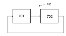
[00053] 도 7은 캘리브레이팅(701) 및 추적(702)의 단계들을 포함하는 알고리즘(700)을 도시한다. 702를 빠져나가고 701에 진입하는 화살표는 캘리브레이션에 이은 추적이 반복될 수 있음을 표시한다. 반복은 한 번, 비주기적으로 또는 예컨대, 1 분 내지 12개월의 간격들로 주기적으로 일어날 수 있다. 반복 횟수는 0일 수 있는데, 즉, 언제나 단 한 번의 캘리브레이션만이 수행될 수 있다. 바람직하게는, 시스템은 초기에 1-3 분의 간격들과 같이 시간적으로 근접하게 이격된 적어도 3 또는 4번의 캘리브레이션들을 특정 피험자에 대해 수행한 다음, 15 내지 60 분과 같은 더 큰 시간 간격들의 캘리브레이션들이 이어진다. 캘리브레이션 단계(701) 및 추적 단계(702)는 본원에서 이하에 설명된다. 7 shows an
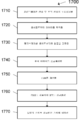
[00054] 도 17은 이하에 설명되는 단계들(1710 내지 1770)을 포함하는 흐름도(1700)를 도시한다. [00054] FIG. 17 shows a flow diagram 1700 including
[00055] 첫째, 포지셔닝[00055] First, positioning
[00056] 첫째로, 단계(1710)에서, 캘리브레이션 센서 및 추적 센서는 특정 피험자에 대해 각각 포지셔닝되어서, 이들 센서들은 그 피험자로부터 바이오메트릭 신호들을 획득할 수 있다. 추적 트랜스듀서는, 추적 데이터를 제공하기 위해 그것이 동맥 펄스를 검출할 수 있는, 피험자에 대한 포지션에 로케이팅된다. 이러한 위치들은, 손목, 손가락, 팔, 몸통, 다리, 발, 머리, 이마, 귓불, 콧방울(nose ala) 및 뺨 근처를 포함한다. 바람직한 실시예에서, 추적 트랜스듀서는 손가락 끝 상에 배치된다. First, in
[00057] 둘째, 양 센서들로부터 데이터의 획득[00057] Second, acquisition of data from both sensors
[00058] 둘째로, 단계(1720)에서, 프로세싱 시스템은 캘리브레이션 센서 및 추적 센서 둘 모두로부터 센서 측정들을 획득한다. 바람직하게는, 프로세싱 시스템은 시간적으로 중복되는, 양 센서들로부터 센서 측정들을 획득한다. 캘리브레이션을 수행하기 위해 프로세싱 시스템에 의해 사용되는 캘리브레이션 센서 및 추적 센서로부터의 신호들 사이의 시간 차이가 작을수록, 결과적인 캘리브레이션에 대한 예상 정확도가 높아진다. 바람직하게는, 프로세싱 시스템은 센서 측정들을 메모리에 저장한다. [00058] Second, in
[00059] 제3 및 제4 단계들은 임의의 순서로 발생할 수 있지만, 제5 단계 이전에 발생해야 한다. [00059] The third and fourth steps can occur in any order, but must occur before the fifth step.
[00060] 셋째, 캘리브레이션 센서로부터 값들의 결정[00060] Third, determination of values from the calibration sensor
[00061] 셋째로, 단계(1730)에서, 프로세싱 시스템은 일정 시간 기간에 걸쳐 캘리브레이션 센서에 의해 감지된 신호들에 기초하여 MAP에 대한 값 및 PP/MAP의 비에 대한 값을 결정한다. 이러한 결정은 센서의 트랜스듀서에 인접하거나 센서의 트랜스듀서로부터 떨어진 회로에 의해 이루어질 수 있다. 프로세싱 시스템은 이 값들을 메모리에 저장한다. Third, in
[00062] 추적 센서는 추적 센서가 신호들을 수신하는 피험자의 동맥들의 구역에서 시간 종속 동맥 혈압 파와 상관되는 시간 종속 신호를 제공하도록 설계된다. [00062] The tracking sensor is designed to provide a time dependent signal that is correlated with a time dependent arterial blood pressure wave in a region of the subject's arteries where the tracking sensor receives signals.
[00063] 넷째, 추적 센서 데이터의 프로세싱[00063] Fourth, processing of tracking sensor data
[00064] 넷째로, 단계(1740)에서, 프로세싱 시스템은 추적 센서로부터의 신호들을 이산 시간 간격 세그먼트들로 분리한다. 각각의 이산 시간 간격 세그먼트는 하나의 심장 시간 기간에 대한 시간에 대응한다. 이들 이산 시간 간격 세그먼트들은 각각 특정 심장 주기를 표현하는 한 세트의 샘플링된 값들을 포함한다. [00064] Fourth, in
[00065] 시스템의 프로세싱은 심장 주기의 시작 및 종료에 대응한다고 가정되는, 추적 센서로부터의 신호의 특징적인 특징들을 결정한다. 예컨대, 시스템은 신호에 대한 로컬 최대치의 시간들, 일부 시간프레임 내의 최대 도함수의 시간 및 추적 센서로부터의 신호의 제2 시간 도함수를 결정하고, 이러한 특징적인 특징들 중 임의의 하나 이상을 사용하여, 하나의 심장 주기의 종료 및 다음 심장 주기의 시작을 표시할 수 있다. 프로세싱 시스템은 또한 각각의 심장 주기의 시작 및 종료를 결정하기 위해, 추적 센서로부터의 신호에 대한 미리 정의된 함수의 상관의 극값을 식별하는 것을 포함할 수 있다. [00065] The processing of the system determines characteristic features of the signal from the tracking sensor, which are assumed to correspond to the start and end of the cardiac cycle. For example, the system determines the times of the local maximum for the signal, the time of the maximum derivative within some timeframe and the second time derivative of the signal from the tracking sensor, and using any one or more of these characteristic features, It can mark the end of one cardiac cycle and the start of the next cardiac cycle. The processing system may also include identifying an extrema of the correlation of a predefined function to the signal from the tracking sensor to determine the start and end of each cardiac cycle.
[00066] 바람직한 실시예에서, 프로세싱 시스템은 임의의 시간 기간 동안 추적 센서로부터 추적 데이터를 취하고, 그 기간 내에 포함된 동맥 펄스들을 결정한다. 프로세싱 시스템은, 그 임의의 시간 기간에서 완전한 펄스의 부분이 아니라고 결정된 그 임의의 시간 기간의 시작 및 종료의 세그먼트들을 취한다. 추적 시스템은 이러한 세그먼트들을 인접 시간 기간에 연결하여서, 모든 펄스들이 참작되게 한다. [00066] In a preferred embodiment, the processing system takes tracking data from the tracking sensor for an arbitrary period of time and determines arterial pulses included within that period. The processing system takes segments of the beginning and ending of any time period determined to be not part of a complete pulse in that certain time period. The tracking system connects these segments to adjacent time periods so that all pulses are taken into account.
[00067] 시스템은 각각의 이산 시간 간격 세그먼트에 대해 DFT(Discrte Fourier Transform)를 수행하여 각각의 이산 시간 간격 세그먼트에 대한 DFT 값들 및 대응하는 주파수들을 제공한다. 이 DFT는 각각의 이산 심장 시간 기간에 대해, 그 이산 시간 간격에 대한 제1 및 후속 고조파(H0, H1, H2, H3 등)에 대한 값들을 발생시킨다. 캘리브레이션을 위해, 하나의 동맥 펄스에 대응하는 하나의 이산 시간 간격 세그먼트에 대한 값들에 대해서만 DFT를 수행하는 것이 필수적이다. 그러나, 복수의 동맥 펄스들에 대해 이 DFT를 수행하고 이들 복수의 동맥 펄스들로부터의 값들을 사용하는 것이 유용할 수 있다. 심장 주기들의 지속기간은 서로로부터 변동되기 때문에, 각각의 심장 주기에 대한 실제 주파수 값들 또는 등가로, 시간 간격 지속기간을 유지하는 것이 중요하다. 실제 주파수 값들을 유지하는 대신에, 프로세싱 시스템은 시간 간격 지속기간, 또는 각각의 시간 간격 지속기간과 연관된 다수의 샘플들을 저장할 수 있다. [00067] The system performs a Discrete Fourier Transform (DFT) on each discrete time interval segment to provide DFT values and corresponding frequencies for each discrete time interval segment. This DFT generates, for each discrete cardiac time period, values for the first and subsequent harmonics (H0, H1, H2, H3, etc.) for that discrete time interval. For calibration, it is essential to perform DFT on only values for one discrete time interval segment corresponding to one arterial pulse. However, it may be useful to perform this DFT for multiple arterial pulses and use values from these multiple arterial pulses. Since the duration of the cardiac cycles fluctuate from each other, it is important to maintain the time interval duration, with actual frequency values or equivalent for each cardiac cycle. Instead of maintaining actual frequency values, the processing system can store a time interval duration, or multiple samples associated with each time interval duration.
[00068] 제4 단계의 결과는 각각의 동맥 펄스에 대한 추적 신호의 주파수 도메인 표현이다. 프로세싱 시스템은 각각의 동맥 펄스에 대한 추적 신호의 주파수 도메인 표현을 메모리에 저장한다. [00068] The result of the fourth step is a frequency domain representation of the tracking signal for each arterial pulse. The processing system stores in memory a frequency domain representation of the tracking signal for each arterial pulse.
[00069] 그러나, 비록 덜 바람직하지만, 프로세싱 시스템이 복수의 심장 주기들과 동일한 이산 시간 세그먼트에 대해 DFT를 수행하는 것이 또한 가능하다. (이 대안에서, 대응하는 전기 모델은 이 복수의 동맥 펄스들로부터 발생한 대응하는 동맥 혈압을 표현하도록 설계된다. 하나의 동맥 펄스에 대응하는 전기 모델은 아래에서 논의됨.)However, although less desirable, it is also possible for the processing system to perform DFT on the same discrete time segment as a plurality of cardiac periods. (In this alternative, the corresponding electrical model is designed to represent the corresponding arterial blood pressure arising from these plurality of arterial pulses. The electrical model corresponding to one arterial pulse is discussed below.)
[00070] 다섯째, 동맥 펄스들의 추정된 H0들의 결정[00070] Fifth, determination of estimated H0s of arterial pulses
[00071] 다섯째로, 단계(1750)에서, 프로세싱 시스템은 DC 컴포넌트 추정 함수 FSUB에 대한 값을 계산한다. FSUB는 이산 시간 간격 세그먼트의 DFT에 대한 H1, H2, H3 등에 대한 값들; 및 캘리브레이션 센서로부터 유도된 MAP 및 PP 값들의 함수일 수 있다. Fifth, in
[00072] DC 컴포넌트 추정 함수는 실수를 출력한다. DC 컴포넌트 추정 함수는 다음의 형태를 가질 수 있다:[00072] The DC component estimation function outputs a real number. The DC component estimation function can take the form:
[00073] FSUB = F(H1, H2, H3, ..., MAP, PP), 여기서 FSUB는 실수이다. [00073] FSUB = F(H1, H2, H3, ..., MAP, PP), where FSUB is a real number.
[00074] FSUB는 (캘리브레이션 센서 데이터로부터의) 적어도 MAP, PP 및 H1 내지 H10에 대한 값들 중 적어도 하나의 함수여야 한다. [00074] The FSUB must be a function of at least one of the values for at least MAP, PP, and H1 to H10 (from calibration sensor data).
[00075] 일부 실시예들에서,[00075] In some embodiments,
(2)
[00076] ξ는 -0.2 내지 0.2의 범위에 있고; 그리고[00076] ξ is in the range of -0.2 to 0.2; And
[00077] K는 3 내지 8 이다. [00077] K is 3 to 8.
[00078] 바람직하게는, K는 5.56 ±30 %이고, 바람직한 실시예에서 5.56이다. 바람직하게는, ξ는 -.01 내지 .01, 보다 바람직하게는 0이다.[00078] Preferably, K is 5.56 ±30%, in a preferred embodiment is 5.56. Preferably, ξ is -.01 to .01, more preferably 0.
[00079] 피험자의 FSUB/H1의 절대 값은 1 내지 100에서 변동된다. 이 비는 피험자의 각각의 심장 주기마다 변하며 피험자마다 또한 상이하다. (FSUB는 실수이다. H1은 복소수일 수 있음.) 프로세싱 시스템은 펄스들에 대한 DC 컴포넌트 추정 함수 FSUB에 대한 계산된 값들을 메모리에 저장한다. [00079] The absolute value of the subject's FSUB/H1 varies from 1 to 100. This ratio varies with each subject's cardiac cycle and is also different from subject to subject. (FSUB is a real number. H1 can be a complex number.) The processing system stores the calculated values for the DC component estimation function FSUB for pulses in memory.
[00080] 여섯째, FSUB에 대해 결정된 값을 사용한, 추적 센서로부터 획득된 값들의 DFT의 정규화Sixth, normalization of the DFT of values obtained from the tracking sensor using the value determined for the FSUB
[00081] 여섯째로, 단계(1760)에서, 프로세싱 시스템은 하나의 동맥 펄스에 대한 추적 신호로부터의 DFT의 H1, H2, H3 등의 값들을 FSUB에 대한 값으로 나누고, 바람직하게는 결과들을 메모리에 저장한다. 이는 추적 신호에 대한 H1, H2, H3 등을 FSUB 값으로 정규화한다. 이는 정규화된 출력 MEASURE1을 제공한다. MEASURE1은 (시간 도메인의 DC 값에 대응하는) 제로 고조파에 대한 값을 포함하지 않는다. MEASURE1은 H1, H2, H3 등의 정규화된 값들을 포함한다. [00081] Sixth, in
[00082] 일곱째, 정규화된 출력에 대한 모델의 출력의 피팅[00082] Seventh, fitting of the output of the model to the normalized output
[00083] (심혈관 모델에 대응하는) 이러한 유사한 전기 모델의 출력은 추적 트랜스듀서에 의해 감지된 피험자의 구역의 동맥 혈압을 표현한다. 이러한 전기 모델과 피험자의 일부 위치에서의 동맥 혈압에 커플링된 추적 센서의 모델을 결합한 결합된 전기 모델의 출력은 추적 센서의 출력을 제공한다. [00083] The output of this similar electrical model (corresponding to the cardiovascular model) represents the arterial blood pressure of the subject's area as sensed by the tracking transducer. The output of the combined electrical model, which combines this electrical model with a model of a tracking sensor coupled to arterial blood pressure at some location of the subject, provides the output of the tracking sensor.
[00084] 프로세싱 시스템은 모델을 정규화된 출력에 피팅함으로써 결합된 전기 모델의 파라미터들을 결정하도록 구성된다. [00084] The processing system is configured to determine parameters of the combined electrical model by fitting the model to the normalized output.
[00085] 일부 실시예들에서, 전기 모델은 심혈관 시스템의 시간 상수를 모델링하는 모델 시간 상수 τ를 포함한다. 일부 실시예들에서, 전기 모델은 수축기가 시작될 때와 대응하는 심장 주기가 시작되는 결정된 시간 사이의 시간 차이를 표현하는 파라미터 Ts를 포함한다. [00085] In some embodiments, the electrical model includes a model time constant τ that models the time constant of the cardiovascular system. In some embodiments, the electrical model includes a parameter Ts representing the time difference between when the systolic begins and the determined time at which the corresponding cardiac cycle begins.
[00086] MODEL1은 결과적인 MODEL1의 제로 주파수에서의 값이 1이 되도록 결합된 전기 모델의 출력의 값들을 상수로 곱함으로써 정규화된 결합된 전기 모델이다. MODEL1 is a combined electrical model normalized by multiplying the output values of the combined electrical model by a constant so that the value at the zero frequency of the resulting MODEL1 becomes 1.
[00087] 일곱째로, 단계(1770)에서, 프로세싱 시스템은 (1) MODEL1의 출력과 (2) MEASURE1 사이에 피팅을 수행한다. 이 피팅은 고조파 주파수들 H1, H2, H3 등 중 하나 이상에서 평가되는, 바람직하게는 적어도 2개의 고조파 주파수들에서 평가되는, 그리고 바람직한 실시예에서 H1, H2 및 H3 주파수들에서 평가되는 2개의 함수들 간의 차이들을 최소화함으로써 수행된다. 피팅은 어떤 주파수들이 평가되던 간에 모델의 하나의 세트의 파라미터들을 제공한다. 하나의 함수는 결합된 전기 모델의 출력이다. 다른 함수는 MEASURE1이다. 각각의 함수에 대한 도메인 값들은 대응하는 동맥 펄스에 대해 결정된 동일한 고조파 주파수들이다. Seventh, in
[00088] MEASURE1에 대한 결합된 전기 모델의 피팅은 전기 모델의 파라미터들의 값들을 발생시킨다. 프로세싱 시스템은 전기 모델의 파라미터들의 이러한 값들을 메모리에 저장한다. [00088] Fitting the combined electrical model to MEASURE1 results in values of the parameters of the electrical model. The processing system stores these values of the parameters of the electrical model in memory.
[00089] 프로세싱 시스템은 프로세싱 시스템이 캘리브레이션 센서로부터 데이터를 사용하여 MAP 및/또는 PP 값들을 획득할 때 상관되는 복수의 동맥 펄스 시간에 대해 전술한 최소화를 수행할 수 있다. 프로세싱 시스템은 이들 최소화들에 의해 획득된 파라미터들의 세트들 중 하나 이상을 사용하여 이들 파라미터들에 대한 대표적인 값들에 도달할 수 있다. 예컨대, 프로세싱 시스템은 다른 동맥 펄스들로부터의 대응하는 값들과 비교하여 비교적 극단적인 파라미터들의 가중치들을 폐기 또는 감소시킬 수 있다. 결과적으로, MAP 및/또는 PP 값에 의존하는 각각의 캘리브레이션에 대해, 프로세싱 시스템은 전기 모델에 대한 하나의 최종 세트의 파라미터들을 결정한다. [00089] The processing system may perform the above-described minimization for a plurality of arterial pulse times that are correlated when the processing system obtains MAP and/or PP values using data from a calibration sensor. The processing system can use one or more of the sets of parameters obtained by these minimizations to reach representative values for these parameters. For example, the processing system may discard or reduce the weights of relatively extreme parameters compared to corresponding values from other arterial pulses. Consequently, for each calibration that depends on the MAP and/or PP value, the processing system determines one final set of parameters for the electrical model.
[00090] 최소 제곱 피팅 및 대수 피팅과 같은 피팅은 오래되었고 당업계에 잘 알려져 있다. 피팅은, 각각의 지점에서 함수들의 차이의 제곱과 같은, 간격에 걸쳐 두 함수들 사이의 차이의 일부 측정을 최소화한다. 함수들을 데이터 신호들에 피팅하기 위한 알고리즘들은 오래되었고 잘 알려져 있다. 피팅은 데이터가 수신된 특정 피험자에 특유한 전기 모델의 파라미터들에 대한 값들을 발생시킨다. 이러한 개인 모델 파라미터 값들은 모델이 그 피험자에 대해 캘리브레이팅되게 한다. 피험자의 개인 모델 파라미터 값들을 결정하는 것은 그 피험자 및 캘리브레이션 센서로부터 획득된 특정 MAP 값에 대한 캘리브레이션을 완료한다. 종래의 수치 방법이 피팅을 수행하기 위해 사용된다. Fittings such as least squares fittings and logarithmic fittings are old and well known in the art. The fitting minimizes some measure of the difference between two functions over an interval, such as the square of the difference of the functions at each point. Algorithms for fitting functions to data signals are old and well known. Fitting generates values for the parameters of the electrical model specific to the particular subject from which the data was received. These personal model parameter values cause the model to be calibrated for that subject. Determining the subject's personal model parameter values completes the calibration for that subject and the specific MAP value obtained from the calibration sensor. Conventional numerical methods are used to perform the fitting.
[00091] 일부 실시예들에서, 프로세싱 시스템은 에러 함수 "err"를 최소화하며, 이는 다음과 같이 정의된다(그리고 MEASURE1에 대한 결합된 전기 모델의 값들의 차이의 측정임):[00091] In some embodiments, the processing system minimizes the error function "err", which is defined as (and is a measure of the difference in values of the combined electrical model for MEASURE1):
[00092][00092]
(3) 
[00093] "o"는 내적 연산자를 표현하고;[00093] "o" represents the dot product operator;
[00094] H는 고조파 번호를 표현하고; 그리고H represents the harmonic number; And
[00095] W는 가중치 함수이다. W는 값들(1; .5 내지 15; .3 내지 50, 더 높은 고조파들에 대해 임의의 실수)을 가질 수 있다. 바람직하게는, W는 범위의 값들(1; 0.5 내지 5; 2 내지 20 및 더 높은 고조파들에 대해 임의의 실수)을 갖는다. W는 값들: (1, 1, 1); (1, 2, 4); (1, 1.2, 4); (1, 1.2, 6); (1, 1.3, 9); (1, 1.2, 12); 및 (1, 1.1, 14) 및 모든 더 높은 고조파들에 대해 0을 가질 수 있다. [00095] W is a weight function. W can have values (1; .5 to 15; .3 to 50, any real number for higher harmonics). Preferably, W has values in the range (1; 0.5 to 5; 2 to 20 and any real number for higher harmonics). W is the values: (1, 1, 1); (1, 2, 4); (1, 1.2, 4); (1, 1.2, 6); (1, 1.3, 9); (1, 1.2, 12); And (1, 1.1, 14) and 0 for all higher harmonics.
[00096] 추적 센서로부터의 데이터가 캘리브레이션에 사용된 시간의 간격은 MAP의 값을 결정하기 위해 캘리브레이션 센서 데이터가 사용된 시간의 간격과 반드시 중첩될 필요는 없다. 예컨대, 심장 주기들에 걸쳐 피험자의 동맥 혈압 변동들이 시간에 걸쳐 매우 안정적으로 유지되는 경우, MAP 값을 획득하기 위한 시간 간격들 및 캘리브레이션에 사용된 추적 센서로부터 데이터를 획득하기 위한 시간 간격에서의 오프셋들은 모델의 파라미터들의 결과적인 결정을 실질적으로 변경하지 않을 수 있다. 그러나 이러한 두 시간 간격들이 서로 시간적으로 근접할수록, 모델의 캘리브레이션이 더 정확해진다. 바람직하게는, 추적 센서로부터의 데이터가 캘리브레이션에 사용된 시간의 간격 및 MAP에 대한 값을 결정하기 위해 캘리브레이션 센서 데이터가 사용된 시간의 간격은 적어도 일부 중첩을 갖는다. 더욱 바람직하게는, 추적 센서로부터의 데이터가 캘리브레이션에 사용된 시간의 간격 및 MAP 중첩에 대한 값을 결정하기 위해 캘리브레이션 센서 데이터가 사용된 시간의 간격은 50 % 초과의 중첩, 더욱 바람직하게는 90 % 초과의 중첩을 갖고, 가장 바람직하게는 (센서들에 대한 샘플링 레이트들의 정확도 내에서) 동일하다. [00096] The interval of time in which data from the tracking sensor is used for calibration does not necessarily overlap with the interval of time in which the calibration sensor data is used to determine the value of MAP. For example, if the subject's arterial blood pressure fluctuations over cardiac cycles remain very stable over time, the time intervals to obtain the MAP value and the offset in the time interval to obtain data from the tracking sensor used for calibration. May not substantially change the resulting determination of the parameters of the model. However, the closer these two time intervals are in time to each other, the more accurate the model's calibration becomes. Preferably, the interval of time the data from the tracking sensor was used for calibration and the interval of time the calibration sensor data was used to determine the value for MAP have at least some overlap. More preferably, the interval of time the data from the tracking sensor was used for calibration and the interval of time the calibration sensor data was used to determine the value for the MAP overlap is an overlap of more than 50%, more preferably 90%. With excess overlap, and most preferably the same (within the accuracy of the sampling rates for the sensors).
[00097] 따라서, 제7 단계는 하나 이상의 동맥 펄스들에 대한 데이터를 사용하여 획득된 전기 모델의 파라미터들의 대표 값들을 발생시킨다. Thus, the seventh step generates representative values of the parameters of the electrical model obtained using data for one or more arterial pulses.
[00098] 프로세싱 시스템은 이상치 동맥 펄스들이 캘리브레이션에 사용되는 것을 거절하기 위해 추적 센서 신호에 대해 품질 검사를 수행하기 위한 알고리즘을 구현할 수 있다. [00098] The processing system may implement an algorithm for performing a quality check on the tracking sensor signal to reject outlier arterial pulses being used for calibration.
[00099] 결과적으로, 캘리브레이션 센서에 의해 제공된 MAP 및/또는 PP 값들에 기초한 전기 모델에 대한 하나의 세트의 파라미터들이 완료될 때 모델의 캘리브레이션이 완료된다. As a result, calibration of the model is complete when one set of parameters for the electrical model based on the MAP and/or PP values provided by the calibration sensor is completed.
[000100] 동맥 혈압의 추적[000100] Tracking of arterial blood pressure
[000101] 캘리브레이션이 특정 피험자에 대해 완료된 후, 시스템은 (1) 캘리브레이션 동안 메모리에 저장된 전기 모델의 파라미터들에 대한 값들; (2) 캘리브레이션 동안 메모리에 저장된 MAP 및/또는 PP 값들; 및 (3) 추적 센서로부터의 신호를 사용하여, 그 피험자에 대해 시간에 대한 동맥 혈압 값들을 추정할 수 있다. 프로세싱 시스템은 추적 센서로부터 데이터를 연속적으로 수신하고, 펄스별(pulse by pulse) 기반으로 MAP 및/또는 PP를 추정하기 위해 펄스별 연산들을 수행한다. 이 단락에서의 펄스들은 동맥 펄스들을 지칭한다. 여기서 펄스별이라 함은, 프로세싱 시스템이 개별 펄스들에 대해 MAP 및/또는 PP에 대한 값들을 추정한다는 것을 표시한다. 선택적으로, 프로세싱 시스템은 펄스별 결정들을 이용하여 다른 혈역학적 파라미터들을 추정한다. 프로세싱 시스템은 결과적인 추정 MAP 및/또는 PP, 및 시간에 대한 추정 동맥 혈압 값들을 메모리에 저장하거나, 송신하거나, 둘 다를 행할 수 있다. [000101] After calibration is completed for a particular subject, the system includes (1) values for parameters of the electrical model stored in memory during calibration; (2) MAP and/or PP values stored in memory during calibration; And (3) using the signal from the tracking sensor, it is possible to estimate arterial blood pressure values over time for the subject. The processing system continuously receives data from the tracking sensor and performs pulse-by-pulse operations to estimate MAP and/or PP on a pulse by pulse basis. The pulses in this section refer to arterial pulses. By pulse-by-pulse here, we indicate that the processing system estimates values for MAP and/or PP for individual pulses. Optionally, the processing system estimates other hemodynamic parameters using pulse-by-pulse decisions. The processing system may store the resulting estimated MAP and/or PP, and estimated arterial blood pressure values over time in memory, transmit, or both.
[000102] 캘리브레이션 후에, 추적 센서는 동맥 혈압을 검출할 수 있는 포지션에 유지된다. 캘리브레이션 단계 2에서와 같이, 추적은, 추적 센서가 신호들을 수신하는 피험자의 동맥의 구역에서 시간 종속 동맥 혈압 파와 상관되는 시간 종속 신호를 제공한다. [000102] After calibration, the tracking sensor is held in a position capable of detecting arterial blood pressure. As in
[000103] 추적 동안, 캘리브레이션의 제4 단계서와 같이, 프로세싱 시스템은 추적 센서로부터의 신호들을 이산 시간 간격 세그먼트들로 분리한다. 각각의 이산 시간 간격 세그먼트는 하나의 완전한 심장 주기에 대한 시간에 대응한다. 이들 이산 시간 간격 세그먼트들은 각각 특정 심장 주기를 표현하는 한 세트의 샘플링된 값들을 포함한다. 시스템은 각각의 이산 시간 간격 세그먼트에 대해 DFT(Discrete Fourier Transform)를 수행하여 각각의 이산 시간 간격 세그먼트에 대한 DFT 값들 및 대응하는 주파수들을 제공한다. 이러한 DFT는 각각의 심장 시간 기간에 대해 그 이산 시간 간격에 대한 제1 및 후속 고조파들(H0, H1, H2, H3 등)에 대한 값들을 발생시킨다. 심장 주기들의 지속기간은 서로로부터 변동되기 때문에, 각각의 심장 주기에 대한 실제 주파수 값들 또는 등가로, 시간 간격 지속기간을 유지하는 것이 중요하다. 실제 주파수 값들을 유지하는 대신에, 프로세싱 시스템은 시간 간격 지속기간, 또는 각각의 시간 간격 지속기간과 연관된 다수의 샘플들을 저장할 수 있다. [000103] During tracking, as in the fourth step of calibration, the processing system separates the signals from the tracking sensor into discrete time interval segments. Each discrete time interval segment corresponds to a time for one complete cardiac cycle. Each of these discrete time interval segments contains a set of sampled values representing a specific cardiac period. The system performs Discrete Fourier Transform (DFT) for each discrete time interval segment to provide DFT values and corresponding frequencies for each discrete time interval segment. This DFT generates values for the first and subsequent harmonics (H0, H1, H2, H3, etc.) for that discrete time interval for each cardiac time period. Since the duration of the cardiac cycles fluctuate from each other, it is important to maintain the time interval duration, with actual frequency values or equivalent for each cardiac cycle. Instead of maintaining actual frequency values, the processing system can store a time interval duration, or multiple samples associated with each time interval duration.
[000104] 제4 단계의 결과는 각각의 동맥 펄스에 대한 추적 신호의 주파수 도메인 표현이다. 그러나, 캘리브레이션에서와 같이, 비록 덜 바람직하지만, 프로세싱 시스템이 복수의 심장 주기들과 동일한 이산 시간 세그먼트에 대해 DFT를 수행하는 것이 또한 가능하다. (이 대안에서, 대응하는 전기 모델은 이 복수의 동맥 펄스들로부터 발생하는 대응하는 동맥 혈압을 표현하도록 설계된다. 하나의 동맥 펄스에 대한 전기 모델은 아래에서 논의됨.)[000104] The result of the fourth step is a frequency domain representation of the tracking signal for each arterial pulse. However, as in calibration, although less desirable, it is also possible for the processing system to perform DFT on the same discrete time segment as multiple cardiac periods. (In this alternative, the corresponding electrical model is designed to represent the corresponding arterial blood pressure arising from these multiple arterial pulses. The electrical model for one arterial pulse is discussed below.)
[000105] 바람직하게는, 프로세싱 시스템은 정규화 및/또는 피팅에서 기껏해야 처음 5개의 고조파들을 사용하며; 바람직하게는 프로세싱 시스템은 20Hz 미만의 고조파들에 대한 데이터만을 사용한다. [000105] Preferably, the processing system uses at most the first 5 harmonics in normalization and/or fitting; Preferably the processing system only uses data for harmonics below 20 Hz.
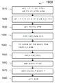
[000106] 도 18은 단계들(1810 내지 1880)을 포함하는, 동맥 데이터를 추적하기 위한 단계들을 도시하는 흐름도(1800)를 도시한다. [000106] FIG. 18 shows a flow diagram 1800 illustrating steps for tracking arterial data, including steps 1810-1880.
[000107] 1810에서, 프로세싱 시스템은 어느 정규화를 사용할지를 결정할 수 있다. 정규화 및 피팅을 수행하기 위한 다음의 2개의 대안들이 설명된다. [000107] At 1810, the processing system can determine which normalization to use. The following two alternatives for performing normalization and fitting are described.
[000108] 제1 정규화 및 피팅 방법[000108] First normalization and fitting method
[000109] 제1 정규화[000109] First normalization
[000110] 추적 동안, 1820에서, 캘리브레이션의 제5 단계에서와 같이, 프로세싱 시스템은 적어도 하나의 동맥 펄스에 대해, 바람직하게는 모든 동맥 펄스들에 대해 DC 컴포넌트 추정 함수(FSUB)에 대한 값을 계산한다. [000110] During tracking, at 1820, as in the fifth step of calibration, the processing system calculates a value for the DC component estimation function (FSUB) for at least one arterial pulse, preferably for all arterial pulses. do.
[000111] FSUB는 이산 시간 간격 세그먼트의 DFT에 대한 H1, H2, H3 등에 대한 값들; 및 캘리브레이션 센서에 의해 결정된 값들로부터 이전에 유도된 MAP 및 PP 값들의 함수일 수 있다. 각각의 동맥 펄스에 대해, 프로세싱 시스템은 FSUB 값을 결정한다. 프로세싱 시스템은 그 동맥 펄스의 H1, H2, H3 등에 대한 값들을, 그 동맥 펄스에 대한 이러한 FSUB 값으로 나눈다. 이는 대응하는 동맥 펄스에 대해 정규화된 고조파 값들을 발생시킨다. [000111] FSUB is values for H1, H2, H3, etc. for the DFT of the discrete time interval segment; And a function of MAP and PP values previously derived from values determined by the calibration sensor. For each arterial pulse, the processing system determines the FSUB value. The processing system divides the values for H1, H2, H3, etc. of the arterial pulse by this FSUB value for the arterial pulse. This produces normalized harmonic values for the corresponding arterial pulse.
[000112] 하나의 캘리브레이션으로부터 MAP 및 PP 값들의 단일 쌍을 사용하는 것에 대안적으로, 프로세싱 시스템은 복수의 캘리브레이션들로부터 MAP 및 PP에 대한 평균값들을 계산할 수 있거나, 또는 복수의 캘리브레이션들로부터 MAP 및 PP에 대한 가중화된 평균값들을 계산할 수 있다. 각각의 동맥 펄스에 대해, 프로세싱 시스템은 그 후, MAP 및 PP의 이들 평균값들, 및 그 동맥 펄스에 대한 대응하는 H1, H2, H3 등에 대한 값들을 사용하여 그 펄스에 대한 FSUB에 대한 값을 결정한다. 프로세싱 시스템은 그 후 그 동맥 펄스의 H1, H2, H3 등에 대한 값들을, 그 동맥 펄스에 대한 이러한 FSUB 값으로 나눈다. 이는 대응하는 동맥 펄스에 대해 정규화된 고조파 값들을 발생시킨다. [000112] Alternatively to using a single pair of MAP and PP values from one calibration, the processing system may calculate average values for MAP and PP from multiple calibrations, or MAP and PP from multiple calibrations. You can calculate the weighted mean values for. For each arterial pulse, the processing system then uses these average values of MAP and PP, and the corresponding values for H1, H2, H3, etc. for that arterial pulse to determine the value for FSUB for that pulse. do. The processing system then divides the values for H1, H2, H3, etc. of the arterial pulse by this FSUB value for the arterial pulse. This produces normalized harmonic values for the corresponding arterial pulse.
[000113] MODEL1로서 제1 피팅 사용[000113] Use of the first fitting as MODEL1
[000114] 추적 동안, 1830에서, 캘리브레이팅의 제7 단계와 유사하게, 프로세싱 시스템은, (1) MODEL1의 출력과 (2) 그 동맥 펄스에 대한 고조파 주파수들에서 대응하는 동맥 펄스에 대한 정규화된 고조파 값들 간의 피팅을 수행한다. 이하에서, 그 동맥 펄스에 대한 고조파 주파수들에서 대응하는 동맥 펄스에 대한 정규화된 고조파 값들은 "MEASURE1"로서 지칭된다. [000114] During tracking, at 1830, similar to the seventh step of calibrating, the processing system is: (1) the output of MODEL1 and (2) normalization for the corresponding arterial pulse at harmonic frequencies for that arterial pulse. Fit between the harmonic values. In the following, the normalized harmonic values for the corresponding arterial pulse at harmonic frequencies for that arterial pulse are referred to as "MEASURE1".
[000115] 프로세싱 시스템은 MEASURE1과 MODEL1 간의 차이들을 최소화함으로써 피팅을 수행한다. 차이들은 고조파 주파수들 H1, H2, H3 등 중 하나 이상에서, 바람직하게는 둘 이상의 고조파 주파수들에서, 그리고 바람직한 실시예에서 고조파 주파수들 H1, H2 및 H3에서 계산될 수 있다. [000115] The processing system performs the fitting by minimizing the differences between MEASURE1 and MODEL1. The differences can be calculated at one or more of the harmonic frequencies H1, H2, H3, etc., preferably at two or more harmonic frequencies, and in a preferred embodiment at the harmonic frequencies H1, H2 and H3.
[000116] 캘리브레이션 및 피팅에 대해 사용되는 특정 전기 모델은 복수의 파라미터들을 포함한다. 추적을 위해 발생하는 피팅 동안, 캘리브레이션 프로세스 동안 결정된 전기 모델의 일부 파라미터들은 일정하게 유지된다. [000116] The specific electrical model used for calibration and fitting includes a plurality of parameters. During the fitting that takes place for tracking, some parameters of the electrical model determined during the calibration process remain constant.
[000117] 바람직하게는, 추적을 위한 피팅 동안 τ 및 Ts가 일정하게 유지된다. [000117] Preferably, τ and Ts are kept constant during fitting for tracking.
[000118] 동맥 펄스에 대해 MEASURE1에 대한 MODEL1의 피팅은 그 동맥 펄스에 대한 MODEL1의 파라미터들의 값들을 발생시킨다. 이 피팅의 결과는 동맥 펄스 당 하나의 세트씩, MODEL1에 대한 다양한 세트들의 파라미터들의 값들이다. Fitting of MODEL1 to MEASURE1 for an arterial pulse results in values of the parameters of MODEL1 for that arterial pulse. The result of this fitting is the values of various sets of parameters for MODEL1, one set per arterial pulse.
[000119] 제2 정규화 및 피팅 방법[000119] Second normalization and fitting method
[000120] 제1 정규화에 대해 대안적으로, 1860에서, 프로세싱 시스템은 제2 정규화를 수행한다. [000120] Alternatively to the first normalization, at 1860, the processing system performs a second normalization.
[000121] 제2 정규화[000121] Second normalization
[000122] 캘리브레이션 동안과 달리, 프로세싱 시스템은 캘리브레이션 신호의 DC 컴포넌트에 대해 정규화하지 않는다. 대신에, 프로세싱 시스템은 동맥 펄스에 대한 추적 신호로부터의 DFT의 H1, H2, H3 등에 대한 값을 H1에 대한 값의 크기로 나눈다. 이는 추적 신호에 대한 H1, H2, H3 등을 정규화한다. 이하에서, 이러한 정규화된 값들 및 대응하는 주파수들은 "MEASURE2"라 칭해진다. MEASURE2 값들은 복소수일 수 있다. MEASURE2의 기본 고조파의 크기는 정의상 1(H1을 H1의 크기로 나눔)이다. Unlike during calibration, the processing system does not normalize to the DC component of the calibration signal. Instead, the processing system divides the value for H1, H2, H3, etc. of the DFT from the tracking signal for the arterial pulse by the magnitude of the value for H1. This normalizes H1, H2, H3, etc. for the tracking signal. In the following, these normalized values and corresponding frequencies are referred to as "MEASURE2". MEASURE2 values may be complex numbers. The magnitude of the fundamental harmonic of MEASURE2 is 1 (H1 divided by the size of H1) by definition.
[000123] 제2 피팅[000123] Second fitting
[000124] 추적 동안, 1870에서, 캘리브레이팅의 제7 단계와 유사하게, 프로세싱 시스템은 이하 본원에서 MODEL2로서 지칭되는 결합된 전기 모델의 출력과 MEASURE2 사이에 피팅을 수행한다. [000124] During tracking, at 1870, similar to the seventh step of calibrating, the processing system performs a fitting between MEASURE2 and the output of the combined electrical model, hereinafter referred to as MODEL2.
[000125] MODEL2는 그의 제1 고조파 값의 크기가 1이 되도록 결합된 전기 모델의 출력의 값들을 실수 값 상수로 곱함으로써 정규화된 결합된 전기 모델이다. [000125] MODEL2 is a combined electric model normalized by multiplying the output values of the combined electric model by a real value constant so that the magnitude of the first harmonic value thereof becomes 1.
[000126] 프로세싱 시스템은 제로(DC) 고조파를 제외하고 미리 정의된 수의 고조파들에 대해 피팅을 수행한다. 프로세싱 시스템은 고조파 주파수들 H1, H2, H3 등 중 하나 이상에서, 바람직하게는 둘 이상의 고조파 주파수들에서, 그리고 바람직한 실시예에서 고조파 주파수들 H1, H2 및 H3에서 차이들을 계산할 수 있다. 바람직한 실시예에서, 프로세싱 시스템은 H1, H2 및 H3에서 피팅을 수행한다. [000126] The processing system performs fitting on a predefined number of harmonics excluding the zero (DC) harmonic. The processing system may calculate differences at one or more of the harmonic frequencies H1, H2, H3, etc., preferably at two or more harmonic frequencies, and in a preferred embodiment the harmonic frequencies H1, H2 and H3. In a preferred embodiment, the processing system performs fitting at H1, H2 and H3.
[000127] 캘리브레이션 및 피팅에 대해 사용되는 특정 결합된 전기 모델은 복수의 파라미터들을 포함한다. [000127] The specific combined electrical model used for calibration and fitting includes a plurality of parameters.
[000128] 이러한 제2 피팅 대안에 대해, 캘리브레이션 프로세스 동안 결정된 전기 모델의 일부 파라미터들은 추적 동안 피팅을 위해 일정하게 유지된다. 바람직하게는, 이 피팅 동안 τ 및 Ts는 일정하게 유지된다. [000128] For this second fitting alternative, some parameters of the electrical model determined during the calibration process remain constant for fitting during tracking. Preferably, τ and Ts remain constant during this fitting.
[000129] 동맥 펄스에 대해 MEASURE2에 대한 MODEL2의 피팅은 그 동맥 펄스에 대한 MODEL2의 파라미터들의 값들을 발생시킨다. 이 피팅의 결과는 동맥 펄스 당 하나의 세트씩, MODEL2에 대한 다양한 세트들의 파라미터들의 값들이다. 일부 실시예들에서, MEASURE2에 대한 MODEL2의 피팅은 MODEL2 및 MEASURE2가 MODEL1 및 MEASURE1을 대체하는 것을 제외하면 "err"와 같은 에러 함수를 사용한다. [000129] Fitting MODEL2 to MEASURE2 for an arterial pulse results in values of the parameters of MODEL2 for that arterial pulse. The result of this fitting is the values of various sets of parameters for MODEL2, one set per arterial pulse. In some embodiments, the fitting of MODEL2 to MEASURE2 uses an error function such as "err" except that MODEL2 and MEASURE2 replace MODEL1 and MEASURE1.
[000130] 프로세싱 시스템은 피험자의 바이오메트릭 파라미터들을 표현하는 값들을 추정하기 위해 동맥 펄스에 대한 모델의 파라미터들의 값들 및 그 모델을 사용할 수 있다. 이들은, Ps, Pd, MAP, 동맥 펄스 당 SV, 대동맥의 직경, 길이 및 강성, 동맥 펄스 당 심장 펌핑 에너지, 심장 탄력, 심장 언로드 볼륨, 수축기말 볼륨 및 이완기말 볼륨을 포함한다. [000130] The processing system may use the values of the parameters of the model for the arterial pulse and the model to estimate values representing the biometric parameters of the subject. These include Ps, Pd, MAP, SV per arterial pulse, diameter, length and stiffness of the aorta, cardiac pumping energy per arterial pulse, cardiac elasticity, cardiac unloading volume, end-systolic volume and end-diastolic volume.
[000131] 여덟째, MAP 추정[000131] Eighth, MAP estimation
[000132] 1840에서, 프로세싱 시스템은 MAP를 추정하기 위해 다음 2개의 대안들 중 하나를 사용한다. [000132] At 1840, the processing system uses one of the following two alternatives to estimate the MAP.
[000133] MAP를 추정하는 제1 방법[000133] The first method of estimating MAP
[000134] 프로세싱 시스템은 동맥 펄스에 대한 MAP에 대한 하나 이상의 값들이 w0calib; MAPcalib; 및 w0est에 대한 값들을 포함하는 값들의 함수의 결과인 것으로 추정한다. 펄스에 대한 MAP의 하나의 이러한 추정은 MAPest이며, 이는 다음과 같이 정의된다. [000134] The processing system includes one or more values for MAP for arterial pulses w 0 calib; MAPcalib; And values for w 0 est. One such estimate of MAP for a pulse is MAPest, which is defined as follows.
(4) 
[000135] w0calib는 특정 캘리브레이션 동안 피팅으로부터 획득된 하나의 특정 모델 파라미터의 대표 값이다. 이 단락에서 "대표 값"이라는 문구는 캘리브레이션의 제7 단계에 대해 논의된 대표 값들을 지칭한다. [000135] w 0 calib is a representative value of one specific model parameter obtained from fitting during a specific calibration. The phrase “representative value” in this paragraph refers to the representative values discussed for the seventh step of calibration.
[000136] MAPcalib은 그 특정 캘리브레이션에 대해 캘리브레이션 동안 획득된 MAP에 대한 값이다. [000136] MAPcalib is the value for the MAP obtained during calibration for that particular calibration.
[000137] w0est는 동맥 펄스에 대한 추적 데이터의 피팅으로부터 획득된 동일한 특정 전기 모델 파라미터의 값이다. [000137] w 0 est is the value of the same specific electrical model parameter obtained from fitting of the tracking data for an arterial pulse.
[000138] 바람직하게는, 프로세싱 시스템은 함수에 대한 값을 컴퓨팅함으로써 MAPest를 추정한다:[000138] Preferably, the processing system estimates the MAPest by computing the value for the function:
(5) 
[000139] P는 다항식을 표현한다. [000139] P represents a polynomial.
[000140] Q는 다항식을 표현한다. [000140] Q represents a polynomial.
[000141] 일 실시예에서,[000141] In one embodiment,
(6) 
[000142] 현재의 바람직한 실시예에서,[000142] In the present preferred embodiment,
(7) 
[000143] K2, K3 및 K4는 피험자 의존적일 수 있다. 피험자 의존의 대해, 프로세싱 시스템은 상이한 캘리브레이션들을 사용하여 결정된 측정된 MAPest 사이의 에러를 최소화하는 K2, K3 및 K4에 대한 값들을 결정함으로써 K2, K3 및 K4를 결정할 수 있다. 예컨대, 상이한 캘리브레이션들로부터의 상이한 MAPCalib 값들에 의해 결정되는 바와 같은 동맥 펄스에 대한 MAPest의 값들에 대한 차이들이 계산되고 그 후, 제곱될 수 있다. 프로세싱 시스템은 그 후 그 합을 최소화하는 K2, K3 및 K4 값들을 결정할 수 있다. 이 프로세스는 복수의 동맥 펄스들에 대한 MAPest의 값들에 대한 데이터로 확장될 수 있다. [000143] K2, K3 and K4 may be subject dependent. For subject dependence, the processing system can determine K2, K3 and K4 by determining values for K2, K3, and K4 that minimize the error between the measured MAPest determined using different calibrations. For example, differences for the values of MAPest for an arterial pulse as determined by different MAPCalib values from different calibrations can be calculated and then squared. The processing system can then determine the K2, K3 and K4 values that minimize the sum. This process can be extended with data on values of MAPest for multiple arterial pulses.
[000144] 동맥 펄스에 대한 MAP의 다른 추정은 아래에서 정의되는 MAPout(n)이다. [000144] Another estimate of MAP for arterial pulses is MAPout(n), defined below.
[000145] 프로세싱 시스템은 MAPest 이상치들을 필터링할 수 있다. 예컨대, 프로세싱 시스템은 MAPout(n)를 컴퓨팅하기 위해 MAPest를 필터링할 수 있다. 예컨대, MAPout에 대한 값들에 대해 다음의 지수 필터를 수행함으로써,[000145] The processing system can filter the MAPest outliers. For example, the processing system can filter MAPest to compute MAPout(n). For example, by performing the following exponential filter on values for MAPout,
(8) 
[000146] 여기서: n은 동맥 펄스들의 시퀀스를 식별하는 인덱스이고; MAPout(n)은 n번째 동맥 펄스에 대한 함수의 출력이고; ff는 그의 값이 0 내지 1, 바람직하게는 0.8 내지 0.98; 가장 바람직하게는 0.9 내지 0.95인 망각 팩터(forgetting factor)이고; MAPout(n-1)은 펄스 n-1에 대한 MAPout의 값이고; MAPest(n)은 펄스 n에 대한 MAPest에 대한 값이다. [000146] where: n is an index identifying a sequence of arterial pulses; MAPout(n) is the output of the function for the nth arterial pulse; ff has a value of 0 to 1, preferably 0.8 to 0.98; Most preferably a forgetting factor of 0.9 to 0.95; MAPout(n-1) is the value of MAPout for pulse n-1; MAPest(n) is a value for MAPest for pulse n.
[000147] 프로세싱 시스템은 이상치들인 MAPest의 값들을 제거함으로써 입력 값을 MAPout으로 필터링할 수 있다. 즉, MAP에 대한 일부 규범적인 값 또는 범위로부터의 그의 비교적 큰 차이로 인해 의심된다. [000147] The processing system may filter the input value to MAPout by removing values of MAPest, which are outliers. That is, it is suspected due to its relatively large difference from some normative value or range for MAP.
[000148] MAP를 추정하는 제2 방법[000148] The second method of estimating MAP
[000149] 프로세싱 시스템은 동맥 펄스에 대한 MAP에 대한 하나 이상의 값들이 다양한 캘리브레이션들에 대해 w0calib[i]; MAPcalib[i]; 및 w0est에 대한 값들을 포함하는 값들의 함수의 결과인 것으로 추정하며, 여기서 i = 1, ..., n이다. 펄스에 대한 MAP의 하나의 이러한 추정은 MAPest2이며, 이는 다음과 같이 정의된다: [000149] The processing system includes one or more values for MAP for arterial pulses w 0 calib[i] for various calibrations; MAPcalib[i]; And values for w 0 est, where i = 1, ..., n. One such estimate of MAP for a pulse is MAPest2, which is defined as:
(9) 
[000150] w0calibs는 벡터, 즉 일련의 값들 w0calib[i]이며, i = 1, ..., n이고[000150] w 0 calibs is a vector, that is, a series of values w 0 calib[i], i = 1, ..., n
[000151] MAPcalibs는 벡터, 즉 일련의 값들 MAPcalib[i]이며, i = 1, ..., n이고;[000151] MAPcalibs is a vector, that is, a series of values MAPcalib[i], i = 1, ..., n;
[000152] w0est는 위에서 정의되었다. [000152] w 0 est was defined above.
[000153] w0calib[i](i = 1, ..., n)은 각각, n개의 캘리브레이션들의 각각의 것에 대한 피팅으로부터 획득된 하나의 특정 모델 파라미터의 대표 값이다. 이 단락에서 "대표 값"이라는 문구는 캘리브레이션의 제7 단계에 대해 논의된 대표 값들을 지칭한다. [000153] w 0 calib[i](i = 1, ..., n) is a representative value of one specific model parameter obtained from fitting for each of the n calibrations, respectively. The phrase “representative value” in this paragraph refers to the representative values discussed for the seventh step of calibration.
[000154] 바람직하게는, 프로세싱 시스템은 함수에 대한 값을 컴퓨팅함으로써 MAPest2를 추정한다:[000154] Preferably, the processing system estimates MAPest2 by computing the value for the function:
(10)
[000155] AVG()는 가중화된 평균을 표현하는 연산자이다. [000155] AVG() is an operator expressing a weighted average.
[000156] P 및 Q는 각각 다항식을 표현하고 w0est 및 w0calib는 위에서 정의되었다. (다항식 Q는 본원에서 설명된 전기의 파라미터로서 특정된 Q와 동일한 양을 표현하지 않음.)[000156] P and Q represent polynomials, respectively, and w 0 est and w 0 calib were defined above. (Polynomial Q does not express the same quantity as Q specified as a parameter of the electricity described herein.)
[000157] 일 실시예에서,[000157] In one embodiment,
(11) 
(12) 
[000158] 현재의 바람직한 실시예에서,[000158] In the present preferred embodiment,
(13) 
(14) 
**는 "승수"를 나타내고 ff2는 0 내지 1의 수이다. ** stands for "multiplier" and ff2 is a number from 0 to 1.
바람직하게는 ff2는 0.3 내지 0.7이고, 보다 바람직하게는 ff2는 0.45 내지 0.55이다Preferably ff2 is 0.3 to 0.7, more preferably ff2 is 0.45 to 0.55.
[000159] 동맥 펄스에 대한 MAP의 다른 추정은 아래에서 정의되는 MAPout2(n)이다. [000159] Another estimate of MAP for arterial pulses is MAPout2(n), defined below.
[000160] 프로세싱 시스템은 MAPest2 이상치들을 필터링할 수 있다. 예컨대, 프로세싱 시스템은 MAPout2(n)을 컴퓨팅하기 위해 MAPest2를 필터링할 수 있다. 예컨대, MAPout2에 대한 값들에 대해 다음의 지수 필터가 수행된다. [000160] The processing system can filter the MAPest2 outliers. For example, the processing system can filter MAPest2 to compute MAPout2(n). For example, the following exponential filter is performed on values for MAPout2.
(16) 
[000161] 여기서: n은 동맥 펄스들의 시퀀스를 식별하는 인덱스이고; MAPout2(n)은 n번째 동맥 펄스에 대한 함수의 출력이고; ff는 값이 0 내지 1, 바람직하게는 0.8 내지 0.98; 가장 바람직하게는 0.9 내지 0.95인 망각 팩터이고; MAPout2(n-1)은 펄스 n-1에 대한 MAPout2의 값이고; MAPest2(n)은 펄스 n에 대한 MAPest2에 대한 값이다. [000161] where: n is an index identifying the sequence of arterial pulses; MAPout2(n) is the output of the function for the nth arterial pulse; ff has a value of 0 to 1, preferably 0.8 to 0.98; Most preferably a forgetting factor of 0.9 to 0.95; MAPout2(n-1) is the value of MAPout2 for pulse n-1; MAPest2(n) is the value for MAPest2 for pulse n.
[000162] 프로세싱 시스템은 이상치들인 MAPest2의 값들을 제거함으로써 입력 값을 MAPout2로 필터링할 수 있다. 그것은 MAP에 대한 일부 규범적인 값 또는 범위로부터의 그의 비교적 큰 차이로 인해 의심된다. [000162] The processing system may filter the input value to MAPout2 by removing values of MAPest2, which are outliers. It is suspected due to its relatively large difference from some normative value or range for MAP.
[000163] 아홉째, PP의 추정[000163] Ninth, estimation of PP
[000164] 1850에서, 프로세싱 시스템은 PP를 추정하기 위해 다음 대안들 중 하나를 수행한다. [000164] At 1850, the processing system performs one of the following alternatives to estimate the PP.
[000165] 제1 PP 추정 방법:[000165] The first PP estimation method:
[000166] 제1 PP 추정 방법은 특정 동맥 펄스의 PP를 추정한다. 이 특정 펄스는 추정된 동맥 펄스라 칭해진다. 제1 PP 추정 방법은 다른 동맥 펄스의 PP의 함수로부터 특정 동맥 펄스의 PP2를 추정한다. 이 방정식은:[000166] The first PP estimation method estimates the PP of a specific arterial pulse. This particular pulse is called the estimated arterial pulse. The first PP estimation method estimates the PP2 of a particular arterial pulse from a function of the PP of another arterial pulse. This equation is:
(17) 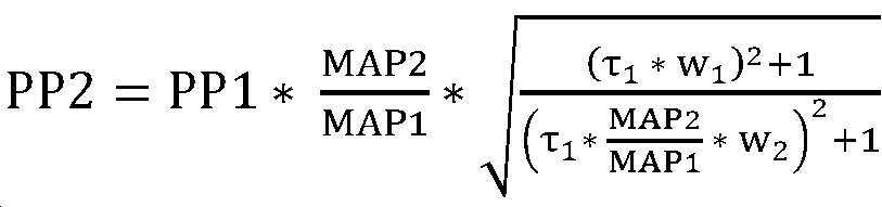
[000167] PP2는 특정 동맥 펄스의 PP이고; PP1은 다른 동맥 펄스의 PP이고; MAP2는 제8 단계에서 결정된 특정 동맥 펄스의 MAP에 대한 값이고; MAP1은 다른 동맥 펄스의 MAP이고;[000167] PP2 is the PP of a specific arterial pulse; PP1 is the PP of another arterial pulse; MAP2 is a value for the MAP of the specific arterial pulse determined in step 8; MAP1 is the MAP of other arterial pulses;
(18) 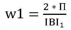
(19) 
[000168] τ1는 다음과 같이 계산될 수 있는 시간 상수이고:[000168] τ 1 is a time constant that can be calculated as follows:
(20) 
[000169] 여기서: 
[000170] PP2는 제1 PP 추정 방법으로부터 발생한 PP의 추정이다. [000170] PP2 is an estimation of PP generated from the first PP estimation method.
[000171] 제2 PP 추정 방법[000171] Second PP estimation method
[000172] 제2 PP 추정 방법은 상이한 방정식을 사용하여 다음과 같이 다른 동맥 펄스의 PP의 함수로부터 특정 동맥 펄스의 PP를 추정한다:[000172] The second PP estimation method uses different equations to estimate the PP of a particular arterial pulse from a function of the PP of other arterial pulses as follows:
(21) 
[000174] PP2는 특정 동맥 펄스에 대한 PP의 추정이고; PP1은 다른 동맥 펄스의 PP이고; MAP2는 제8 단계에서 결정된 특정 동맥 펄스의 MAP이고; MAP1은 다른 펄스의 MAP이다. [000174] PP2 is an estimate of PP for a particular arterial pulse; PP1 is the PP of another arterial pulse; MAP2 is the MAP of the specific arterial pulse determined in the eighth step; MAP1 is the MAP of another pulse.
[000175] PP2는 제2 PP 추정 방법으로부터 발생한 추정된 PP이다. [000175] PP2 is an estimated PP generated from the second PP estimation method.
[000176] 열 번째로, 1880에서, 프로세싱 시스템은 Ps 및/또는 Pd를 추정한다. [000176] Tenth, at 1880, the processing system estimates Ps and/or Pd.
[000177] 프로세싱 시스템은 MAP 및 PP의 함수들을 사용하여 PP 및 MAP로부터 Ps 및/또는 Pd를 추정할 수 있다. 일반적으로:[000177] The processing system may estimate Ps and/or Pd from PP and MAP using the functions of MAP and PP. Generally:
[000178] 
[000179] 
[000180] 이러한 2개의 함수들에 대한 종래의 선택들은 다음과 같다:[000180] Conventional choices for these two functions are as follows:
(22)
(23)
[000181] 일 실시예에서, MAP는 제8 단계의 결과이고, PP는 제9 단계의 결과이다. [000181] In one embodiment, MAP is the result of the eighth step, and PP is the result of the ninth step.
[000182] SV 결정 및 SVV 추정[000182] SV determination and SVV estimation
[000183] 도 19는 SV를 추정하기 위해 아래에서 설명된 단계들(1910-1980)을 포함하는 흐름도(1900)를 도시한다. [000183] FIG. 19 shows a
[000184] 프로세싱 시스템은 펄스별 기반으로 SV에 대한 상대 값을 결정한다. 임의의 2개의 펄스들에 대한 SV의 비는 SVV의 측정이다. 복수의 SV에서의 통계적 변동들은 복수의 펄스들로부터의 SV들의 비들에 의해 결정될 수 있다. 이러한 통계적 변동들은 SVV에 대한 측정들이다. 통상적으로, SVV는 다수의 동맥 펄스들에 대한 SV의 표준 편차를 이러한 SV들의 평균으로 나눈 것을 표현하는 정규화된 표준 편차를 지칭한다. 프로세싱 시스템은 이러한 정규화된 표준 편차를 계산함으로써 SVV에 대한 값을 결정한다. [000184] The processing system determines a relative value for the SV on a per pulse basis. The ratio of SV to any two pulses is a measure of SVV. Statistical fluctuations in the plurality of SVs can be determined by the ratios of the SVs from the plurality of pulses. These statistical variations are measurements of SVV. Typically, SVV refers to the normalized standard deviation representing the standard deviation of the SV for multiple arterial pulses divided by the average of these SVs. The processing system determines a value for SVV by calculating this normalized standard deviation.
[000185] 프로세싱 시스템은 다음과 같이 펄스별 기반으로 SV에 대한 상대 값을 결정한다. 동맥 펄스들의 시퀀스에 대응하는 시간 기간에 대한 추적 데이터를 획득한 후, 위에서 논의된 바와 같이, 프로세싱 시스템은 일련의 동맥 펄스들의 각각의 하나에 대한 시작 시간에 대응하는 시간들을 결정하도록 신호의 특징적인 특징들을 사용한다. [000185] The processing system determines a relative value for SV on a pulse-by-pulse basis as follows. After obtaining trace data for a time period corresponding to the sequence of arterial pulses, as discussed above, the processing system determines the times corresponding to the start time for each one of the series of arterial pulses. Use features.
[000186] 프로세싱 시스템은 시스템 여기(system excitation)로서 강제 함수(forcing function)가 사용되는 모델의 계수들을 결정한다. 강제 함수는 전기 모델의 전류를 표현하며 피험자의 심장을 빠져나가는 혈류에 대응한다. 계수들은 심장으로부터 추적 센서가 데이터를 획득하는 포지션으로의 혈액의 전달 효과에 대응한다. 프로세싱 시스템은 강제 함수의 계수들 및 값들과 추적 데이터의 선형 결합을 등식화(equate)한다. 강제 함수 및 추적 데이터는 시간 도메인 또는 주파수 도메인으로 표현될 수 있다. 방정식들에서의 미지수(unknown)들은 SV들에 대한 (실수) 값들이다. 어느 경우든, 결과는 일련의 커플링된 선형 방정식들이며, 이는 SV들의 시퀀스에 대한 상대 값들을 결정하기 위해 종래의 방식으로 풀어질 수 있다. 모델은 심장 주기 시작 시간들과 강제 함수에서 특징적인 특징(예컨대, 최대치 또는 도함수의 몇 승(some power) 시에 최대치)이 존재하는 시간들 사이에 고정(즉, 펄스 독립적)되나, 미지의 시간 차이가 존재한다고 가정한다. SV들이 실수가 되도록 요구하는 것은 시간 차이가 결정되는 것 그리고 방정식들이 풀어지는 것을 가능하게 한다. 주파수 도메인에서 푸는 것이 바람직하지만, 프로세싱 시스템은 시간 도메인에서 또한 풀 수 있다. 아래 SV에 대한 해법 프로세스는 선형 대수에 의존하며, 행렬 반전을 사용하여 아래에 공식화된 방정식들의 세트를 푼다. 가우시안 제거, 크라머의 방법, LU 분해, 레빈슨(Levinson) 재귀 등과 같은 다른 방법들이 또한 사용될 수 있다. [000186] The processing system determines the coefficients of the model in which a forcing function is used as system excitation. The forcing function represents the current in the electrical model and corresponds to the blood flow exiting the subject's heart. The coefficients correspond to the effect of delivery of blood from the heart to the position where the tracking sensor acquires data. The processing system equalizes the linear combination of the tracking data with the coefficients and values of the coercion function. The forcing function and tracking data may be expressed in the time domain or the frequency domain. Unknowns in the equations are the (real) values for SVs. In either case, the result is a series of coupled linear equations, which can be solved in a conventional manner to determine the relative values for the sequence of SVs. The model is fixed (i.e., pulse-independent) between the cardiac cycle start times and the times at which a characteristic feature (e.g., maximum or maximum at some power of the derivative) exists in the forcing function, but the unknown time Assume that a difference exists. Requiring the SVs to be real makes it possible for the time difference to be determined and the equations to be solved. Solving in the frequency domain is preferred, but the processing system can also solve in the time domain. The solution process for the SV below relies on linear algebra and solves the set of equations formulated below using matrix inversion. Other methods such as Gaussian removal, Kramer's method, LU decomposition, Levinson recursion, etc. can also be used.
[000187] SV 추정 단계 1: 1910에서, 프로세싱 시스템은 추적 센서 데이터에서 순차적인 심장 주기 시작 시간들을 결정한다. 프로세싱 시스템은 n개의 인접한 시작 시간들을 선택한다. 이러한 시작 시간들은 T1, T2, ..., Tn이다. n개의 심장 주기들의 총 지속기간은 시간 세그먼트, 
[000188] 1920, SV 추정 단계 2: 1920에서, 프로세싱 시스템은 동맥 펄스들의 시퀀스에 대응하는 시간 기간에 대한 추적 센서 데이터를 푸리에 변환한다. 이 단계의 결과는 일련의 값들 및 대응하는 주파수들이다. 주파수들은 0, 1/Tseg, 2/Tseg, ....이다. 1920, SV Estimation Step 2: At 1920, the processing system Fourier transforms the tracking sensor data for a time period corresponding to the sequence of arterial pulses. The result of this step is a series of values and corresponding frequencies. The frequencies are 0, 1/Tseg, 2/Tseg, ....
[000189] SV 추정 단계 3: 1930에서, 프로세싱 시스템은 SV 추정에 사용될 n개의 주파수들을 선택하며, 여기서 n은 SV 추정 단계 1에서 결정된 심장 주기들의 수이다. 바람직하게는, n개의 주파수들은 
[000190] SV 추정 단계 4: 1935에서, 프로세싱 시스템은 피험자의 SV와 동맥 혈압 사이의 관계를 표현하는 일부 전기 모델의 주파수 응답을 평가한다. 바람직하게는, 이 전기 모델은 캘리브레이션에 대해 사용되는 전기 모델이다. 바람직하게는, 이 전기 모델의 파라미터들은 정규화된 출력 MEASURE1에 대해 전기 모델의 출력을 피팅할 때 캘리브레이션으로부터 결정된 파라미터들이다. 프로세싱 시스템은 SV 추정 단계 3에서 결정된 주파수들에서 이 전기 모델을 평가한다. 결과들은 이들 주파수들에서의 주파수 응답 값들이다. SV Estimation Step 4: At 1935, the processing system evaluates the frequency response of some electrical models representing the relationship between the subject's SV and arterial blood pressure. Preferably, this electrical model is the electrical model used for calibration. Preferably, the parameters of this electrical model are those determined from the calibration when fitting the output of the electrical model to the normalized output MEASURE1. The processing system evaluates this electrical model at the frequencies determined in
[000191] SV 추정 단계 5: 1940에서, 프로세싱 시스템은 SV 추정 단계 2로부터 획득된 푸리에 변환의 각각의 값을 대응하는 모델 응답 값으로 나눈다. 결과는 실제 데이터를 단계 2에서 결정된 n개의 주파수들에 대한 모델 데이터로 나눈 비인 n개의 값들의 순서화된 시퀀스이다. 이 순서화된 시퀀스 벡터를 "R"이라고 칭한다. SV estimation step 5: In 1940, the processing system divides each value of the Fourier transform obtained from
[000192] SV 추정 단계 6: 1950에서, 프로세싱 시스템은 n × n 행렬 M의 값들을 결정한다. 행렬 M의 제1 행은, SV 추정 단계 3에서 선택된 n개의 주파수들 중 제1 주파수 w1에서 디랙(Dirac) 델타 함수들의 시퀀스의 푸리에 변환인 값들을 포함한다. [000192] SV estimation step 6: In 1950, the processing system determines values of the n × n matrix M. The first row of the matrix M includes values that are Fourier transforms of a sequence of Dirac delta functions at a first frequency w1 among n frequencies selected in
[000193] M의 제1 행 및 제1 열 엘리먼트는 M(1, 1)이다. M(1, 1)은 주파수 w1에서 제1 디랙 델타 함수의 푸리에 변환의 값을 저장한다. M(1, 2)은 주파수 w1에서 제2 디랙 델타 함수의 푸리에 변환의 값을 저장하는 식이다. M(2,1)은 주파수 w2에서 제1 디랙 델타 함수의 푸리에 변환의 값을 저장한다. M(2, 2)은 주파수 w2에서 제2 디랙 델타 함수의 푸리에 변환의 값을 저장하는 식이다. M(n, n)은 주파수 wn에서 마지막 디랙 델타 함수의 푸리에 변환의 값을 저장한다. M(i, k)는 
[000194] 바람직한 실시예에서, 프로세싱 시스템은 이 행렬 M을 반전시켜 행렬 invM을 결정한다. [000194] In a preferred embodiment, the processing system determines the matrix invM by inverting this matrix M.
[000195] SV 추정 단계 7: 1970에서, 프로세싱 시스템은 행렬 방정식에서 Z의 허수 부분을 최소화하는 값 deltaT를 결정한다:[000195] SV estimation step 7: In 1970, the processing system determines a value deltaT that minimizes the imaginary part of Z in the matrix equation:
(24) 
(25) Z는 복소수 값들의 n x 1 행렬이고; (25) Z is an
[000196] invL은 행렬 값들(포지션 1, 1에서 


[000197] 바람직하게는, 프로세싱 시스템은 deltaT의 값을 결정하기 위해 Z의 컴포넌트들의 값들의 함수인 에러 함수를 최소화하는 최소화 알고리즘을 수행한다. 그러나, deltaT는 또한 직접 해법 방법들, 예컨대 선형 대수 방법들에 의해 결정 가능하게 될 수 있다. 하나의 적합한 에러 함수는 다음과 같다:[000197] Preferably, the processing system performs a minimization algorithm that minimizes an error function, which is a function of the values of the components of Z, to determine the value of deltaT. However, deltaT may also be made determinable by direct solution methods, such as linear algebra methods. One suitable error function is:
(26) 
[000198] "**"는 "승수"를 의미한다. [000198] "**" means "multiplier".
[000199] im()은 허수 부분을 의미하고;Im() means an imaginary part;
[000200] sum()은 모든 인수들의 합을 의미하고; 그리고[000200] sum() means the sum of all arguments; And
[000201] Z(i)는 Z에 대한 i번째 값이다. [000201] Z(i) is the i-th value for Z.
[000202] 적합한 최소화 알고리즘들은 잘 알려져 있고, L-BFGS-B, Nelder-Mead, Powell, 공액 기울기(conjugate gradient), BFGS, 뉴턴-공액 기울기, 절두 뉴턴 알고리즘, 선형 근사에 의한 제한된 최적화(Constrained Optimization BY Linear Approximation), 순차적 최소 제곱 프로그래밍(Sequential Least Squares Programming), 및 차동 에볼루션(Differential Evolution)을 포함한다. [000202] Suitable minimization algorithms are well known, and L-BFGS-B, Nelder-Mead, Powell, conjugate gradient, BFGS, Newton-conjugate slope, truncated Newton algorithm, limited optimization by linear approximation (Constrained Optimization BY Linear Approximation), Sequential Least Squares Programming, and Differential Evolution.
[000203] SV 추정 단계 7의 결과는 deltaT에 대한 값이다. [000203] The result of SV estimation step 7 is a value for deltaT.
[000204] SV 추정 단계 8: 1980에서, 프로세싱 시스템은 SV 단계 7에서 정의된 바와 같이 invL에서 SV 추정 단계 7에서 발견된 deltaT에 대한 값을 교체하고, 다음을 계산하고:[000204] SV estimation step 8: In 1980, the processing system replaces the value for deltaT found in SV estimation step 7 in invL as defined in SV step 7, and calculates:
(27) 
[000205] SV는 컴포넌트들 SV(i)(i = 1 내지 n)의 순서화된 시퀀스이고; [000205] SV is an ordered sequence of components SV(i) (i = 1 to n);
real()은 인수의 컴포넌트들 각각의 실수 부분을 결정하는 연산자이고; 그리고 real() is an operator that determines the real part of each of the components of the argument; And
R은 위에서 정의된 순서화된 서열 벡터이다. R is an ordered sequence vector as defined above.
[000206] 프로세싱 시스템은 SV의 컴포넌트들의 값들을 사용하여 SVV를 계산할 수 있다. [000206] The processing system can calculate the SVV using the values of the components of the SV.
[000207] 복수의 심장 주기들에 걸쳐있는 추적 데이터에 대한 피팅[000207] Fitting for tracking data spanning multiple cardiac cycles
[000208] 프로세싱 시스템은 복수의 심장 주기들과 동일한 이산 시간 세그먼트에 대한 추적 데이터의 DFT를 수행할 수 있다. 이 경우에, 전기 모델의 구동 함수는 그 복수의 펄스들을 갖는 구동 함수를 표현한다. 이러한 심장 주기들의 각각의 것은 그것과 연관된 특정 SV를 갖는다. 이 경우에, 프로세싱 시스템은 SV 추정 방법을 사용하여 각각의 펄스에 대한 구동 함수의 진폭을 세팅할 수 있다. [000208] The processing system may perform DFT of tracking data for the same discrete time segment as a plurality of cardiac periods. In this case, the driving function of the electric model represents the driving function having its plurality of pulses. Each of these cardiac cycles has a specific SV associated with it. In this case, the processing system can use the SV estimation method to set the amplitude of the drive function for each pulse.
[000209] 바람직한 시스템 및 방법[000209] Preferred systems and methods
[000210] 바람직한 방법은 자동 혈압계를 사용하여 피험자의 Ps 및 Pd를 측정한다. 자동 혈압계는 통상적으로 측정을 위해 오실로메트릭 방법(oscillometric method)을 사용한다. 자동 혈압계들은 커프에 압력을 가한 후 감압(그 반대의 경우도 마찬가지임)하고, 커프가 수축하거나 팽창함에 따라 혈압들의 측정들을 행한다. 자동 혈압계들은 일련의 (하나 초과의) 심장 주기들에 걸쳐 발생하는 커프 팽창 또는 수축 동안 캡처된 데이터에 기초하여 Ps에 대한 하나의 값, Pd에 대한 하나의 값 및 MAP에 대한 하나의 값을 결정한다. 자동 혈압계가 Ps 또는 Pd 또는 MAP에 대한 값(또는 이러한 값들의 임의의 결합)을 결정하기 위해 데이터를 취하는 시간 기간은 일반적으로 대략 10초 정도이며, 이는 일반적으로 피험자의 약 10번의 심장 주기들에 대응한다. [000210] A preferred method is to measure Ps and Pd of the subject using an automatic blood pressure monitor. Automatic blood pressure monitors typically use the oscillometric method for measurement. Automatic blood pressure monitors apply pressure to the cuff and then decompress (and vice versa), and take measurements of blood pressures as the cuff contracts or expands. Automatic blood pressure monitors determine one value for Ps, one value for Pd and one value for MAP based on data captured during cuff inflation or contraction that occurs over a series of (more than one) cardiac cycles. do. The time period for which the automatic sphygmomanometer takes data to determine a value for Ps or Pd or MAP (or any combination of these values) is typically on the order of 10 seconds, which is typically in about 10 cardiac cycles of the subject. Corresponds.
[000211] 바람직하게는, 추적 센서는, 혈압계가 동일한 피험자에 대한 Ps, Pd 및/또는 MAP를 결정하는 데이터를 혈압계가 수신하는 기간 기간 동안 그 피험자로부터의 추적 신호를 제공한다. [000211] Preferably, the tracking sensor provides a tracking signal from a subject during a period in which the blood pressure monitor receives data for determining Ps, Pd and/or MAP for the same subject.
[000212] 바람직하게는, 단일 디바이스 하드웨어는 자동 혈압계의 데이터 및 추적 센서의 신호 둘 모두를 수신한다. 일 실시예에서, 단일 하드웨어 디바이스는 PCM이다. 종래의 PCM들은 통상적으로 심장 박동 및 혈액 산소 레벨을 나타내는 신호들을 포함하여 인간으로부터 측정된 다양한 바이오메트릭 신호들을 수신하고, 이러한 바이오메트릭 파라미터들의 시간 의존적 시각적 디스플레이를 제공한다. [000212] Preferably, the single device hardware receives both the data of the automatic blood pressure monitor and the signal of the tracking sensor. In one embodiment, the single hardware device is a PCM. Conventional PCMs typically receive various biometric signals measured from humans, including signals indicative of heart rate and blood oxygen level, and provide a time dependent visual display of these biometric parameters.
[000213] "Estimating the relationship between MAP value and pulse amplitude and methods to achieve so"이라는 제목의 미국 가출원 번호 제62/609,435호는, 개별 동맥 펄스에 대한 파형 및 개별 동맥 펄스에 대한 MAP에 대한 알려진 값, 및 하나의 동맥 펄스에 대한 Ps 및 Pd에 대한 알려진 값들로부터, 개별 동맥 펄스에 대한 Ps 및 Pd를 추정하기 위한 하나의 방법을 개시한다. [000213] U.S. Provisional Application No. 62/609,435, entitled "Estimating the relationship between MAP value and pulse amplitude and methods to achieve so," discloses known values for waveforms for individual arterial pulses and MAP for individual arterial pulses, And from known values for Ps and Pd for one arterial pulse, one method for estimating Ps and Pd for individual arterial pulses.
[000214] 캘리브레이션 후에, 각각의 동맥 펄스에 대한 MAP, Ps 및 Pd를 추정하기 위해 추적 센서 데이터가 사용된다. [000214] After calibration, tracking sensor data is used to estimate MAP, Ps and Pd for each arterial pulse.
[000215] 시스템은 또한 추적 센서에 의해 제공된 신호로부터 유도된 SVV에 대한 추정기를 포함한다.[000215] The system also includes an estimator for SVV derived from the signal provided by the tracking sensor.
[000216] 도면의 간단한 설명
[000217] 도 1은 본 발명의 제1 실시예인 시스템(100) 및 피험자의 사지와 시스템(100)의 상호관계를 도시한다.
[000218] 도 2는 본 발명의 제2 실시예인 시스템(200) 및 피험자의 사지와 시스템(200)의 상호관계를 도시한다.
[000219] 도 3은 본 발명의 제3 실시예인 시스템(300) 및 피험자의 사지와 시스템(300)의 상호관계를 도시한다.
[000220] 도 4는 추적 트랜스듀서(102)의 전기 컴포넌트들의 개략도이다.
[000221] 도 5는 도 2 및 도 3의 하드웨어 조립체(201)의 상세한 설명을 도시한다.
[000222] 도 6은 추적 트랜스듀서 프론트 엔드(502)의 상세한 설명을 도시한다
[000223] 도 7은 반복적인 캘리브레이팅 및 추적 활동들을 포함하는 알고리즘(700)을 도시하는 흐름도이다.
[000224] 도 8은 (심혈관 모델에 대응하는) 전기 모델(804) 및 추적 센서(805)의 모델을 포함하는 결합된 전기 모델(800)의 전기 개략도를 도시한다.
[000225] 도 9는 도 8의 엘리먼트(802)의 일 실시예의 전기 개략도이다.
[000226] 도 10은 도 8의 엘리먼트(802)의 대안적인 실시예의 전기 개략도이다.
[000227] 도 11은 도 8의 2-포트 네트워크(803)의 일 실시예를 표현하는 2-포트 네트워크(1100)의 개략도이다.
[000228] 도 12는 동맥 펄스들의 시퀀스를 포함하는 파형 및 캘리브레이션의 방법을 설명하는 데 도움이 되는 표시들을 도시한다.
[000229] 도 13은 피팅 전에 추적 데이터(측정) 및 모델 데이터 둘 모두에 대한 2개의 플롯들(하나는 고조파 주파수에 대한 실수 컴포넌트들의 값들에 대한 것이고; 하나는 고조파 주파수에 대한 허수 컴포넌트들의 값들에 대한 것임)을 도시한다.
[000230] 도 14는 피팅 이후에 추적 데이터(측정) 및 모델 데이터 둘 모두에 대한 2개의 플롯들(하나는 고조파 주파수에 대한 실수 컴포넌트들의 값들에 대한 것이고; 하나는 고조파 주파수에 대한 허수 컴포넌트들의 값들에 대한 것임)을 도시한다.
[000231] 도 15는 심혈관 모델에 대응하는 개략적 전기 회로(1500)이다.
[000232] 도 16은 피험자의 심장 SV들에 대한 동맥 펄스 트레인들 및 시간 대응; 및 델타 함수들을 도시한다.
[000233] 도 17은 캘리브레이션의 단계들을 도시하는 흐름도이다.
[000234] 도 18은 추적의 단계들을 도시하는 흐름도이다.
[000235] 도 19는 일회박출량 추정을 도시하는 흐름도이다.[000216] Brief description of the drawings
[000217] FIG. 1 shows a
[000218] FIG. 2 shows the
[000219] FIG. 3 shows a
4 is a schematic diagram of electrical components of the tracking
5 shows a detailed description of the
[000222] Figure 6 shows a detailed description of the tracking transducer
[000223] FIG. 7 is a flow diagram illustrating an
[000224] FIG. 8 shows an electrical schematic diagram of a combined
[000225] FIG. 9 is an electrical schematic diagram of one embodiment of
[000226] FIG. 10 is an electrical schematic diagram of an alternative embodiment of
[000227] FIG. 11 is a schematic diagram of a two-
[000228] Figure 12 shows a waveform comprising a sequence of arterial pulses and indications to help explain the method of calibration.
13 is two plots for both tracking data (measurement) and model data before fitting (one for the values of real components for harmonic frequency; one for values of imaginary components for harmonic frequency) For).
14 is two plots for both tracking data (measurement) and model data after fitting (one for values of real components for harmonic frequency; one for values of imaginary components for harmonic frequency) For).
15 is a schematic
16 shows arterial pulse trains and time correspondence for heart SVs of a subject; And delta functions.
[000233] Figure 17 is a flow chart showing steps of calibration.
[000234] FIG. 18 is a flowchart showing steps of tracking.
[000235] Figure 19 is a flow chart showing the once stroke amount estimation.
[000236] 실시예들의 상세한 설명[000236] Detailed description of the embodiments
[000237] 도 1은 제1 실시예의 시스템(100) 및 피험자의 팔(101)과의 그의 구조적 상호관계를 도시한다. 시스템(100)은 PCM(103), 커프(110) 및 추적 트랜스듀서(102)를 포함한다. [000237] Figure 1 shows the
[000238] 추적 트랜스듀서(102)는 PPG 트랜스듀서를 포함하고 피험자의 손가락(106) 상에 장착된다. 케이블(107)은 추적 트랜스듀서(102)를 PCM(103)에 연결한다. 커프(110)는 피험자의 팔 주위에 장착된다. 2개의 튜브들(109)은 커프(110)를 PCM(103)에 연결한다. 커프(110), 튜브들(109) 및 PCM(103)은 오실로메트릭 커프 기반 혈압계를 포함한다. 바람직하게는, 추적 트랜스듀서(102)는 커프(110)에 의해 혈류가 차단되지 않는 피험자의 구역 이를테면, 커프 맞은편의 손가락으로부터 신호들을 획득한다. [000238] The
[000239] PCM(103)은 디스플레이(104) 및 사용자 제어들(108)을 포함한다. The
[000240] 디스플레이(104)는 바람직하게는, 시간(104)에 대한 바이오메트릭 데이터의 그래픽 표현을 디스플레이할 수 있다. 도 1에 도시된 바와 같이 시간에 대한 바이오메트릭 데이터는 동맥 혈압을 포함할 수 있다. 디스플레이(104)는 바람직하게는, 바이오메트릭 데이터의 시간 평균들을 표현하는 수치 데이터(105)를 디스플레이할 수 있다. 도 1에 도시된 바와 같은 수치 데이터(105)는 HR(Heart Rate), Ps, Pd, MAP 및 SVV를 포함할 수 있다. [000240] The
[000241] 제어들(108)은 바람직하게는, 시간에 대한 상이한 바이오메트릭 데이터(이를테면, ECG 및/또는 압력 파)를 그래픽으로 디스플레이하고, 그래픽 디스플레이의 시간 스케일을 변경하고, 시간 평균화된 수치 데이터(105)를 획득하는 데 사용되는 동맥 펄스들의 시간 또는 수를 변경하도록, 사용자가 PCM(103)을 프로그래밍하는 것을 가능하게 한다. 제어들(108)은 또한 순차적인 캘리브레이션들 사이의 시간 지연들을 제어하거나, 또는 즉각적인 캘리브레이션을 활성화하는 데 사용될 수 있다. [000241] The
[000242] PCM(103), 튜브들(109) 및 커프(110)는 Ps, Pd 및 MAP가 추정될 수 있는 압력 변동들의 측정을 가능하게 한다. Ps의 측정은 통상적으로, 커프가 수축되거나 팽창함에 따라 Pd의 측정 이전 또는 이후 수 초 내지 1 분 미만 안에 발생한다. 바람직하게는, PCM(103)은 커프 기반 측정들로부터 MAP에 대한 값, Ps에 대한 값 및 Pd에 대한 값을 결정하도록 프로그래밍된다. [000242] The
[000243] PCM(103)은 Intel ™ 17 프로세서와 같은 적어도 하나의 수치 프로세서를 포함한다. 바람직하게는, 이러한 적어도 하나의 프로세서는 커프(110) 및 추적 트랜스듀서(102)에 의해 변환된 데이터에 대해 수학적 알고리즘들을 실행한다. 바람직하게는, 이러한 적어도 하나의 프로세서는 추적 트랜스듀서(102) 및 커프(110)에 의해 변환된 데이터로부터, 디스플레이(104)에 도시된 바와 같은 HR, Ps, Pd, MAP 및 SVV 수치 값들 및 동맥 혈압 파 중 하나 이상을 결정한다. [000243] The
[000244] 도 2는 시스템(200)의 물리적 컴포넌트들 및 피험자의 팔(101)을 도시한다. 시스템(200)은 하드웨어 조립체(201) 및 PCM(103)을 포함한다. 2 shows the physical components of the
[000245] 하드웨어 조립체(201)는 PCM(103)의 인클로저와 별개의 인클로저를 포함한다. 케이블(107)은 추적 트랜스듀서(102)를 PCM(103)에 연결한다. 대안적으로, 케이블(107)은 브랜치(branch)를 포함할 수 있으며, 이 브랜치는 하드웨어 조립체(201)에 연결되는 브랜치로부터의 일 측 및 PCM(103)에 연결되는 브랜치로부터 다른 측을 갖는다. 튜브(109)는 커프(110)를 하드웨어 조립체(201)에 연결한다. 2개의 튜브들(203)은 하드웨어 조립체(201)를 PCM(103)에 연결한다. 이들 튜브들은 커프(110)와 PCM(103) 사이에서 압력을 통신한다. 대안적으로, 튜브들(109)은 압력을 하드웨어 조립체(201) 및 PCM(103) 둘 모두에 직접 통신하기 위한 브랜치들을 포함할 수 있다. [000245] The
[000246] 전기 연결(202)은 하드웨어 조립체(201)를 PCM(103)에 연결한다. 전기 연결(202)은 하드웨어 조립체(201)와 PCM(103) 사이에서 단방향성(PCM(103)으로부터 하드웨어 조립체(201)로) 또는 양방향성 통신을 제공한다. [000246]
[000247] PCM(103)으로부터 하드웨어 조립체(201)로의 단방향 통신의 경우에, 하드웨어 조립체(201)는 PCM(103) 캘리브레이션 센서 값들(이를테면, 커프(110)로부터의 데이터로부터 결정된 값들) 및 선택적으로 추적 센서 값들(이를테면, 추적 트랜스듀서들에 의해 생성된 값들)을 수신하고 선택적으로 전기 연결(204)을 사용하여 추정된 압력 파를 PCM에 통신한다. 와이어들(204)은 아날로그 연결을 위한 4개의 와이어들을 포함한다. 와이어들(204)은 예컨대, 디스플레이될 동맥 혈압 값들을 PCM(103)에 제공한다. [000247] In the case of one-way communication from the
[000248] 하드웨어 조립체(201)와 PCM(103) 사이의 양방향성 통신의 경우에, 전기 연결(202)은 또한 데이터를 PCM(103)에 전송할 수 있다. 전기 연결(202)은 PCM(103) 상의 디스플레이를 위해 캘리브레이션 센서(커프(110)) 및 추적 트랜스듀서(102)로부터 유도된 데이터 중 임의의 하나 이상을 PCM(103)에 전송할 수 있다. 임의의 특정 PCM 모델에 의해 요구되는 데이터 포맷들과 같은 원하는 출력 데이터 포맷들로 데이터를 변환하기 위한 PCM 인터페이스들의 설계는 잘 알려져 있다. 임의의 특정 PCM에 대해 요구되는 특정 데이터 포맷은 임의의 특정 PCM 제조자에 독점적일 수 있다. 그러나, 인터페이스의 독점적 포맷, 프로그래밍 또는 설계를 감안하면, 전기 연결(202)을 통한 이러한 통신들은 완전히 당업자의 능력 및 일상적인 엔지니어링 및 프로그래밍의 문제 내에 있다. [000248] In the case of bidirectional communication between
[000249] 하드웨어 조립체(201)로부터 PCM(103)으로 전달된 데이터는 시간 의존적 트레이스들 및 수치 데이터를 포함하여, PCM(103)에 의한 디스플레이를 위한 임의의 값을 포함할 수 있다. PCM 또는 하드웨어 조립체(201) 앞에 있는 사람에 대한 경고와 관련하여, 경고들은 피험자의 바이오메트릭 조건들 또는 바이오메트릭 데이터가 신뢰할 수 없다는 결정들에 기초할 수 있다. 예컨대, 하드웨어 조립체(201) 또는 PCM(103)은 바이오메트릭 데이터가 비신뢰성을 표시할 때를 결정하는 신뢰성 알고리즘을 적용할 수 있다. 예컨대, 비신뢰성은, 추적 센서의 출력 신호의 낮은 신호 대 잡음 비; 순차적인 심장 시간 기간들로부터 유도된 데이터의 비교적 큰 변화들; (예컨대, 수치 근사 알고리즘의 수렴의 결여로 인한) 동맥 펄스와 그의 모델의 매칭의 장애에 의해 표시될 수 있다. 예컨대, 경고들은 사운드 또는 시각적 표시기, 및 선택적으로 경고에 대한 특정 이유의 사운드 또는 시각적 표시를 포함할 수 있다. [000249] The data transferred from the
[000250] 도 2의 PCM(103)은 도 1의 PCM(103)과 유사하지만, PCM(103)으로부터 하드웨어 조립체(201)로 데이터를 통신하기 위해 라인(202)에 연결된 포트를 또한 포함한다. 이 포트는 캘리브레이션 센서 값들을 판독하고 선택적으로 PCM으로부터 센서 값들을 또한 추적하는 데 사용된다. 다른 실시예에서, 이 연결은 와이어(202)를 통해 하드웨어 조립체(201)로부터 PCM(103)으로 추정된 BPV 값들, BPV 트레이스 값들 및 경보들의 통신을 가능하게 한다. [000250]
[000251] 하드웨어 조립체(201)는 커프(110) 및 추적 트랜스듀서(102)로부터 자신이 수신한 신호들, 및 선택적으로 PCM(103)으로부터 자신이 수신된 신호들을 프로세싱하여 피험자에 대한 동맥 혈압을 표현하는 디지털 신호를 생성한다. [000251] The
[000252] 대안적으로, 무선 송신기들은 제1 및 제2 구조적 실시예들에 대해 위에서 설명된 와이어들을 대체할 수 있다. [000252] Alternatively, wireless transmitters may replace the wires described above for the first and second structural embodiments.
[000253] 대안적으로, 완전한 혈압계(커프를 가압 및 수축시키는 수단을 포함함)는 제1 및 제2 구조적 실시예들에 대해 위에서 설명된 커프(110)를 대체할 수 있고, 유선 또는 무선 송신기들 및/또는 트랜시버들은 이러한 완전한 혈압계를 PCM(103) 또는 PCM(103) 및 하드웨어 조립체(201)에 커플링할 수 있다. 이 대안에서, PCM(103) 및 하드웨어 조립체(201)의 혈압계의 엘리먼트들은 요구되지 않는다. [000253] Alternatively, a complete blood pressure monitor (including means to pressurize and deflate the cuff) may replace the
[000254] 제1 및 제2 구조적 실시예들에서, 바람직하게는, PCM(103)은 혈압계의 압력 구동 엘리먼트들을 포함한다. [000254] In the first and second structural embodiments, preferably, the
[000255] 도 3은 시스템(300)의 물리적 컴포넌트들 및 피험자의 팔(101)을 도시한다. 시스템(300)은 하드웨어 조립체(201), PCM(103) 및 외부 디스플레이(302)를 포함한다. 3 shows the physical components of the
[000256] 도 3은 하드웨어 조립체(201)에 대한 외부 디스플레이(302)의 연결(301)을 도시한다. 외부 디스플레이(302)는 하드웨어 조립체(201)로부터의 BPV 데이터를 디스플레이할 수 있다. 추적 트랜스듀서(102)는 하드웨어 조립체(201), PCM(103) 또는 둘 모두에 연결될 수 있다. 3 shows a
[000257] 도 4는 발광 다이오드들(401 및 402); 광검출기 PIN 다이오드(403), 케이블(107) 내의 와이어들(405 내지 410), 및 인증 디바이스(411)를 포함하는 추적 트랜스듀서(102)의 전기 컴포넌트들의 개략도이다. 이러한 종류의 추적 트랜스듀서는 피험자 기관 상에 장착될 때 그 기관의 부분에서의 광 흡수의 변화들을 검출할 수 있는 하나 이상의 광 감지 디바이스들과 하나 이상의 발광 디바이스들의 결합을 포함한다. 트랜스듀서(102)는 광 소스 및 동맥 혈압에 대응하는 박동 컴포넌트를 구별할 수 있는 검출기를 포함한다. 신호의 DC 컴포넌트는 피부 조직의 대량 흡수에 기인하는 반면, AC 컴포넌트는 심장 주기에 대응하는 압력에 의해 야기되는, 그것이 배치된 신체 기관의 혈액량의 변동에 직접적으로 기인한다. 통상적으로 2개의 광 소스들은 발광 다이오드들(401 및 402)이다. LED(401)는 940nm의 파장을 갖는 적외선을 방출하고, LED(402)는 660nm의 파장을 갖는 적색 광을 방출한다. 이들 파장들은 통상적인 값이고, 때때로 또한 사용되는 녹색 광을 포함하여 적외선 및 가시 구역들의 다른 파장들이 사용될 수 있다. 트랜스듀서는 또한 광검출기 PIN 다이오드(403)를 포함한다. 추적 트랜스듀서는 선택적으로 또한, 트랜스듀서에 고유한 ID를 제공하는 인증 디바이스(411)를 포함한다. 이러한 어레인지먼트(arrangement)는 조립체(201) 내의 적절한 제공과 함께, 사전에 다른 피험자에 대해 사용되었던 트랜스듀서가 피험자에게 장착되는 것을 방지할 것이다. 선택적 인증 디바이스(411)는, 고유한 ID로 프로그래밍되고 Maxim Semiconductors에 의한 DS28E05와 같은 단일 접촉 단일 와이어 인터페이스(single contact one wire interface)를 갖는 집적 회로 ROM을 포함한다. 4 shows light-emitting
[000258] 추적 트랜스듀서(102)는 케이블(107)을 통해 적합한 인터페이스에 연결된다. 케이블(107)은 통상적으로 4개 또는 6개의 와이어들을 포함한다. 광 소스들을 위한 한 쌍의 와이어들(405, 406), 광검출기를 위한 한 쌍의 와이어들(407, 408) 및 선택적으로 인증 디바이스를 위한 한 쌍의 와이어들(409,410)이 존재한다. [000258] The
[000259] 도 5는 압력 센서(501); 추적 트랜스듀서 프론트 엔드(502); 프로세싱 시스템(503); 디지털-아날로그(D/A) 변환기(505); PCM에 대한 인터페이스(504); 및 디스플레이 인터페이스(506)를 포함하는 하드웨어 조립체(201)를 도시한다. 이러한 모든 회로 블록들은 디지털 버스(507)를 통해 상호 연결된다. 5 is a
[000260] 회로 블록들: 압력 센서(501); 추적 트랜스듀서 프론트 엔드(502); 디스플레이 인터페이스(506); 및 D/A 변환기(505)는 선택적이다. 압력 센서(501)는 커프(110)에 제공된 공기 압력을 감지한다. PPG 프론트 엔드(502)는 추적 트랜스듀서(102)와 인터페이스하고 프로세싱 시스템(503)에 대한 인터페이스를 제공한다. 프로세싱 시스템(503)은 실시간 BPV 및/또는 SVV 추정 알고리즘들을 실행할 수 있다. 프로세싱 시스템(503)은 BPV 및/또는 SVV 데이터를, 인터페이스 회로(504); D/A 변환기(505); 및 디스플레이 인터페이스(506) 중 하나 이상에 통신할 수 있다. [000260] Circuit blocks:
[000261] 실시예들에서, 인터페이스 회로(504)는 PCM(103)에 의해 제공된 캘리브레이션 데이터 및 선택적으로, 또한, 추적 트랜스듀서(102)에 의해 PCM(103)에 전송된 데이터를 판독한다. 실시예들에서, 추적 트랜스듀서는 조립체(201)와 직접 인터페이스하고, PCM에 대한 인터페이스(504)는 캘리브레이션 데이터를 판독하기 위해 PCM(103)과 인터페이스한다. 실시예들에서, PCM에 대한 인터페이스(504)는 추정된 압력 값들을 PCM(103)에 전송한다. 일 실시예에서, 이 데이터는 D/A 변환기(505)를 사용하여 아날로그 형태로 PCM(103)에 전송된다. 실시예들에서, 인터페이스 회로(504)는 BPV 및/또는 SVV 데이터를 PCM(103)과 호환 가능한 형태로 변환하고, 공식적으로 호환 가능한 데이터를 와이어(202)를 통해 PCM(103)에 송신한다. 인터페이스 회로(304)는 송신 직렬 RS232 연결, USB, 이더넷(LAN), 또는 PCM(103)이 BPV 및 SVV 데이터를 수신할 수 있는 임의의 다른 데이터 포맷을 위해 데이터를 포맷할 수 있다. In embodiments, the
[000262] 하드웨어 조립체(201)와 PCM(103) 사이의 양방향성 통신의 경우에, 인터페이스(504)는 또한 데이터를 PCM(103)에 전송할 수 있다. 인터페이스(504)는 PCM(103) 상의 디스플레이를 위해 캘리브레이션 센서(커프(110)) 및 추적 트랜스듀서(102)로부터 유도된 데이터 중 임의의 하나 이상을 PCM(103)에 전송할 수 있다. 임의의 특정 PCM 모델에 의해 요구되는 데이터 포맷들과 같은 원하는 출력 데이터 포맷들로 데이터를 변환하기 위한 인터페이스들의 PCM 설계는 잘 알려져 있다. 임의의 특정 PCM에 대해 요구되는 특정 데이터 포맷은 임의의 특정 PCM 제조자에 독점적일 수 있다. 그러나, 인터페이스의 독점적 포맷, 프로그래밍 또는 설계를 감안하면, 이러한 인터페이스(504)는 완전히 당업자의 능력 및 일상적인 엔지니어링 및 프로그래밍의 문제 내에 있다. [000262] In the case of bidirectional communication between the
[000263] 도 6은 추적 트랜스듀서 인터페이스 회로(502)를 도시한다. 추적 트랜스듀서가 추적 트랜스듀서 인터페이스와 연결될 때, 이들은 함께, 피험자 조직에서 혈액의 관류를 모니터링하는 데 통상적으로 사용되는 광혈류 측정 센서(photoplethysmographic sensor)의 기능을 제공한다. [000263] Figure 6 shows a tracking
[000264] 추적 트랜스듀서 인터페이스 회로(502)는 트랜스임피던스 증폭기(601); 필터 회로(602); 아날로그-디지털(A/D) 변환기(603); LED 드라이버(604); 전류 제어 D/A 변환기(605); 및 디지털 인터페이스 회로(606)를 포함한다. [000264] The tracking
[000265] LED 드라이버(604)는 전류 펄스를 LED들로 드라이빙한다. 이들 펄스들의 전류는 전류 제어 DAC(605)에 의해 제어되며, 이 전류 제어 DAC는 차례로 디지털 인터페이스 회로(606)에 의해 제어된다. 광검출기(403)로부터의 신호는 트랜스임피던스 증폭기(601)에 의해 증폭되고, 필터 회로(602)에 의해 필터링되고 A/D 디지털 변환기(603)에 의해 샘플링된다. 603으로부터의 신호는 디지털 인터페이스 회로(606)에 연결된다. 디지털 인터페이스 회로(606)는 버스(507)를 통해 프로세서에 연결된다. 케이블(107)이 브랜치를 포함하며, 이 브랜치로부터의 일 측은 하드웨어 조립체(201)에 연결되고 브랜치로부터의 다른 측은 PCM(103)에 연결되는 경우에, LED 드라이버(604) 및 전류 제어 D/A 변환기(605)는 필요하지 않으며 구현되지 않을 수 있다. [000265] The
[000266] 결합된 전기 모델[000266] Combined Electric Model
[000267] 도 8은 심혈관 시스템 전기 모델(804) 및 센서 시스템 모델(805)을 포함하는 결합된 전기 모델(800)을 도시한다. [000267] FIG. 8 shows a combined
[000268] 심혈관 시스템 전기 모델(804)은 전류 소스(801); 부하(802); 2-포트 네트워크(803); 전류 소스(801)의 출력과 부하(802) 및 2-포트 네트워크(803) 둘 모두의 입력 사이의 등전위 전위 연결(807)을 포함한다. [000268] The cardiovascular system
[000269] 센서 시스템 모델(805)은 다른 2-포트 네트워크를 정의한다. 센서 시스템 모델(805)은 2-포트 네트워크(803)의 출력과 등전위를 갖는 입력을 갖는다. 엘리먼트들(801; 802; 803; 및 805)의 모든 기준 단자들은 공통 접지에 레퍼런스된다.[000269] The
[000270] 센서 시스템 모델(805)의 출력(806)은 결합된 전기 모델(800)의 출력이다. [000270] The
[000271] 결합된 전기 모델(800)의 주파수 도메인 출력 신호는 다음에 의해 정의된다:[000271] The frequency domain output signal of the combined
(28)
[000272] w는 주파수를 표현하고;[000272] w represents the frequency;
[000273] N은 실수이고;[000273] N is a real number;
[000274] Xh(w)는 전류 소스(801)에 의해 생성된 전류를 표현한다. [000274] Xh(w) represents the current generated by the
[000275] Zl(w, MAP)은 부하(802)의 입력 임피던스를 표현한다. Zl(w, MAP) represents the input impedance of the
[000276] Hx(w)는 무한 입력 임피던스를 갖는 2-포트(803)의 전달 함수를 표현한다. [000276] Hx(w) represents the transfer function of the two-
[000277] Hs(w)는 2-포트(805)의 전달 함수를 표현한다. [000277] Hs(w) represents the transfer function of the 2-
[000278] Xh는 심장의 펌핑을 모델링한다. Zl은 주요 동맥들의 임피던스를 모델링하고; Hx는 압력 측정 위치의 동맥 혈압으로의 심장 근처의 동맥 혈압 출력의 전달을 모델링하고; Hs는 측정 위치의 동맥 혈압으로부터 추적 센서 출력 신호로의 변화를 모델링한다. [000278] Xh models the pumping of the heart. Zl models the impedance of the major arteries; Hx models the delivery of proximal arterial blood pressure output to the arterial blood pressure at the pressure measurement location; Hs models the change from arterial blood pressure at the measurement location to the tracking sensor output signal.
[000279] 에스테리스크(*)는 곱셈을 표현하고; w는 주파수를 표현하고; MAP는 위에서 정의되었다. 모델은 Zl이 유일한 MAP 종속 함수라고 가정한다. [000279] Asterisk (*) represents multiplication; w represents the frequency; MAP was defined above. The model assumes that Zl is the only MAP dependent function.
[000280][000280]
[000281] MODEL1(w)이 MODEL1의 주파수 도메인 출력 신호인 경우:[000281] When MODEL1(w) is the frequency domain output signal of MODEL1:
(29) 
[000282] MODEL1은 본원의 위에서 제1 정규화 및 피팅 방법에서 설명된 바와 같이 결합된 전기 모델로부터의 출력 신호를 표현한다. [000282] MODEL1 represents the output signal from the combined electrical model as described in the first normalization and fitting method above herein.
[000283] MODEL2(w)가 MODEL2의 주파수 도메인 출력 신호인 경우: [000283] When MODEL2(w) is the frequency domain output signal of MODEL2:
(30)
[000284] Xh(w)는 도 8의 심장 함수(801)이고;[000284] Xh(w) is the
[000285] w1은 모델링된 동맥 펄스의 제1 고조파의 주파수이고; W1 is the frequency of the first harmonic of the modeled arterial pulse;
[000286] Zl(w)은 도 8에서 부하(802)에 의해 표현되는 심장 부하 임피던스이고;[000286] Zl(w) is the cardiac load impedance represented by the
[000287] Hx(w)는 심장-손가락 끝 전달 함수이고; 그리고 [000287] Hx(w) is the heart-finger tip transfer function; And
[000288] Hs(w)는 추적 센서 프론트 엔드의 전달 함수이다. [000288] Hs(w) is the transfer function of the tracking sensor front end.
[000289] Xh(w)에 대한 하나의 옵션은 다음과 같다: [000289] One option for Xh(w) is as follows:
(31)
[000290] 이 방정식에서, Γ 및 FT는 모델 파라미터들이고, 
[000291] 본 발명자는 3.0 내지 9.0의 고정된 Γ 값, 바람직하게는 6.154과 동일한 Γ가 BPV를 추적하는 데 충분하다는 것을 발견했다. [000291] The inventors have found that a fixed Γ value of 3.0 to 9.0, preferably Γ equal to 6.154, is sufficient to track BPV.
[000292] FT는 모델 파라미터들 중 하나이다. [000292] FT is one of the model parameters.
[000293] 실시예들에서, 심장 함수는 1인데 즉: Xh(w) = 1이며, 이는 디랙 델타 함수의 푸리에 변환을 표현한다. In embodiments, the cardiac function is 1, ie: Xh(w) = 1, which represents the Fourier transform of the Dirac delta function.
[000294] 실시예들에서, Xh(w)는 삼각파의 푸리에 변환이고:[000294] In embodiments, Xh(w) is the Fourier transform of the triangular wave:
(32) 
[000295] α는 모델 파라미터이다. 실시예들에서, α에 대한 값은 캘리브레이션 동안 결정된다. 실시예들에서, α에 대한 값은 추적 동안 결정된다. [000295] α is a model parameter. In embodiments, the value for α is determined during calibration. In embodiments, the value for α is determined during tracking.
[000296] [000296]
[000297] Hs는 도 8의 2-포트 네트워크(805)의 전달 함수이다. 2-포트 네트워크(805)는 유한 지속기간 출력을 제공하는 저역 통과 필터(FIR 필터) 및 임의의 유한 시간에서 응답이 0이 되지 않는 고역 통과 필터(HR 필터)를 포함할 수 있다. [000297] Hs is the transfer function of the two-
[000298] 도 9는 도 8의 부하(802)의 일 실시예의 전기 개략도를 도시한다. [000298] FIG. 9 shows an electrical schematic diagram of one embodiment of the
[000299] 부하(802)는 저항기(902), 인덕터(903), 커패시터(904) 및 저항기(905)를 포함한다. 저항기들(902, 904)은 공통 접지에 레퍼런스되고, 저항기(902) 및 인덕터(903)는 등전위 전위 연결(807)에 연결된다. 커패시터(904)의 값은 커패시턴스가 MAP에 의존하고 1/MAP에 따라 변동되는 심혈관 모델에 대응한다. [000299] The
[000300] 도 9의 개략도에 대해:[000300] For the schematic diagram of FIG. 9:
(33) 
[000301] S = j*w;[000301] S = j*w;
[000302] 그리고, w0, Q 및 τ는 모델 파라미터들이며;[000302] And, w 0 , Q and τ are model parameters;
[000303] Ts는 대응하는 심장 주기가 시작되는 결정된 시간과 수축기가 시작될 때 사이의 시간 차이를 표현하는 파라미터이고, w0는 제로 주파수이다. [000303] Ts is a parameter representing the time difference between the determined time at which the corresponding cardiac cycle starts and when the systolic starts, and w 0 is the zero frequency.
[000304] 다른 실시예에서, Zl은 다음과 같이 정의된다:[000304] In another embodiment, Z l is defined as follows:
(34) 
[000305] w01, w02, Q, τ 및 Ts는 피팅에 의해 결정되는 모델 파라미터들이다. [000305] w01, w02, Q, τ, and Ts are model parameters determined by fitting.
[000306] 도 10은 도 8의 부하(802)의 대안적인 실시예의 전기 개략도를 도시한다. 도 10에서, 부하(802)는 송신 라인(1001) 및 종단(1002)을 포함한다. 종단(1002)은 송신 라인(1001)에 걸쳐 병렬인 커패시터(1003) 및 저항기(1003)를 포함한다. [000306] FIG. 10 shows an electrical schematic diagram of an alternative embodiment of the
[000307] 부하(802)에 대한 입력 임피던스는 다음과 같다:[000307] The input impedance for the
(35) 
[000308] Z0는 MAP의 함수이고; [000308] Z 0 is a function of MAP;
[000309] Zt는 송신 라인(1001)에 걸쳐 병렬인 커패시터(1003) 및 저항기(1003)에 의해 정의된 종단 임피던스이고;[000309] Zt is the terminating impedance defined by the
[000310] β는 w 및 MAP의 함수이며; 그리고 [000310] β is a function of w and MAP; And
[000311] L은 송신 라인(1001)의 길이이다. [000311] L is the length of the
[000312] 실시예들에서, Z0는 sqrt(MAP)에 비례한다. [000312] In embodiments, Z 0 is proportional to sqrt(MAP).
[000313] 실시예들에서, β는 w*sqrt(MAP)에 비례한다. In embodiments, β is proportional to w*sqrt(MAP).
[000314] 실시예들에서, 커패시터(103)의 커패시턴스는 1/MAP에 비례한다. [000314] In embodiments, the capacitance of the
[000315] 도 11은 도 8의 2-포트 네트워크(803)의 일 실시예를 표현하는 2-포트 네트워크(1100)의 개략도를 도시한다. 2-포트 네트워크(1100)는 입력(1103) 및 출력(1104)을 포함하고, 각각은 2개의 단자들, 송신 라인(1101) 및 종단(1102)을 포함한다. V1 및 V2는 각각 입력 및 출력의 전압들을 표현한다. [000315] FIG. 11 shows a schematic diagram of a two-
[000316] 도 11의 전달 함수는 Hx(w)의 일 실시예이다. 이 전달 함수는 다음과 같다:[000316] The transfer function of FIG. 11 is an embodiment of Hx(w). This transfer function is as follows:
(36) 
[000317] td, Γ는 상수들이다. [000317] t d and Γ are constants.
[000318] 도 12는 파형(1201), 시간(1202), 동맥 펄스(1203) 및 파형(1201)의 파형 세그먼트(1204)를 도시한다. 도 12는 5개의 동맥 펄스들의 시퀀스에 걸친 파형 세그먼트(1204)를 도시한다. 파형 세그먼트(1204)의 모든 동맥 펄스들은 시간(1202)에 대해 시간적으로 비교적 근접하다. 파형 세그먼트(1204)는 시스템들(100, 200, 300)이 캘리브레이션을 위해 추적 데이터를 사용할 수 있는 시간 기간을 예시한다. 파형 세그먼트(1204)에 도시된 5개의 동맥 펄스들은 단지 예시를 위한 것이다. 적어도 하나의 동맥 펄스에 대한 추적 데이터가 사용되는 한, 추적 데이터로부터 더 많거나 더 적은 동맥 펄스들이 사용될 수 있다. 파형(1201)은 추적 트랜스듀서 파형 세그먼트(1204)로부터의 데이터가 복수의 동맥 펄스들을 포함하는 세그먼트를 보여준다는 것을 표현한다. 파형(1201)은, 추적 센서에 의해 모니터링되는 피험자 신체의 위치에서의 동맥 혈압 변화들에 대응하고 심장 주기들의 기간들에 또한 대응하는 세미 반복적(semi repetitive) 동맥 펄스들을 도시한다. 각각의 동맥 펄스는 중박 노치에 대응하는 최소치에 의해 분리된 두 개의 최대치들을 도시하며, 제1 최대치는 제2 최대치보다 높다. 파형(1201)은 본 발명을 예시하기 위한 것이며 따라서 비교적 동일한 동맥 펄스들을 도시한다. 실제 동맥 혈압 파형들은 통상적으로 서로로부터 실질적으로 변동되는 심장 펄스 기간들 및 진폭들을 갖는다. 12 shows
[000319] 바람직하게는, 시간적으로 시간(1202)에 따라 중첩되는 동맥 펄스를 비롯하여, 캘리브레이션에 사용된 추적 데이터로부터의 동맥 펄스들은, 10분의 시간(1202) 내에, 보다 바람직하게는 1분의 시간(1202) 내에, 보다 바람직하게는 20초의 시간(1202) 내에, 가장 바람직하게는 10초의 시간(1202) 내에 발생한다. [000319] Preferably, arterial pulses from tracking data used for calibration, including arterial pulses temporally superimposed over
[000320] 시간(1202)은, 캘리브레이션 센서가 캘리브레이션 값들 Ps, Pd 또는 MAP 값들을 결정한 시간인 것으로 PCM(103) 또는 하드웨어 조립체(201)가 결정한 시간(1202)을 식별한다. 실시예들에서, 프로세싱 시스템은 캘리브레이션 센서가 Ps, Pd 또는 MAP를 결정하는 데 사용된 데이터를 획득한 시간을 결정하고, 그 시간에 가장 근접한 추적 데이터의 동맥 펄스를 식별한다. 예컨대, 펄스(1203)는 시간(1202)에 걸쳐있다. 프로세싱 시스템은 캘리브레이션 프로세스에서 이 펄스(1203)로부터의 데이터를 사용한다. 다른 실시예들에서, 프로세싱 시스템은 캘리브레이션 프로세스에서 펄스(1203) 및 다른 펄스들 이를테면, 인접 펄스들 또는 파형 세그먼트(1204)의 모든 펄스들에 대한 데이터를 사용한다. The
[000321] 일 실시예에서, 동맥 펄스(1203)는 PCM(103)에 의해 또는 압력 센서(501)에서 하나의 심장 주기 동안 가장 큰 압력 등락을 생성하는 것으로서 식별된다. 캘리브레이션 동안, 이 동맥 펄스 주파수 콘텐츠 및 캘리브레이션 값들은 모델을 트레이닝하고 측정된 신호와 가능한 한 근접하게 매칭되는 모델의 파라미터들을 찾는 데 사용된다. In one embodiment,
[000322] 혈압 측정에 사용되는 형태의 커프를 포함하는 실시예들에서, 프로세싱 시스템은 하나의 심장 주기 동안 시간에 따른 압력의 변동이 가장 큰 시점을 결정할 수 있다. 프로세싱 시스템은 위에서 논의된 바와 같이, 캘리브레이션을 위해 이 시간에 근접한 추적 센서 데이터를 사용할 수 있다. [000322] In embodiments including a cuff of a type used for blood pressure measurement, the processing system may determine a point in time at which the fluctuation of pressure over time is greatest during one cardiac cycle. The processing system can use tracking sensor data close to this time for calibration, as discussed above.
[000323] 도 13은 피팅 전에 추적 데이터(측정) 및 모델 데이터 둘 모두에 대한 2개의 플롯들(하나는 고조파 주파수에 대한 실수 컴포넌트들의 값들에 대한 것이고; 하나는 고조파 주파수에 대한 허수 컴포넌트들의 값들에 대한 것임)을 도시한다. 13 is two plots for both tracking data (measurement) and model data prior to fitting (one for the values of real components for harmonic frequency; one for values of imaginary components for harmonic frequency) For).
[000324] 도 13의 상위 플롯은 추적 데이터(측정) 및 모델 데이터에 대한, 고조파 주파수에 대해 실수 컴포넌트들의 값들을 도시한다. 도 13의 하위 플롯은 추적 데이터(측정) 및 모델 데이터에 대한, 고조파 주파수에 대한 허수 컴포넌트들의 값들을 도시한다. 도 13은 선택된 모델을 추적 데이터에 피팅하기 전의 데이터를 도시한다. 도 13은 x 축을 따라 고조파들을 도시한다. 이러한 고조파들의 주파수들은 정수를 심장 펄스 기간으로 나눈 것이다. [000324] The upper plot of FIG. 13 shows values of real components versus harmonic frequency, for tracking data (measurement) and model data. The lower plot of FIG. 13 shows values of imaginary components for harmonic frequency, for tracking data (measurement) and model data. 13 shows data before fitting the selected model to tracking data. 13 shows harmonics along the x axis. The frequencies of these harmonics are an integer divided by the duration of the heart pulse.
[000325] 도 13은 모델에 대한, (기본 주파수에 값 1, 2 3을 곱한 것들에 대한) 고조파들 및 DC 컴포넌트에 대한 값들을 도시한다. [000325] FIG. 13 shows values for harmonics and DC component (for fundamental frequency multiplied by
[000326] 도 13은 (하나의 심장 시간 기간 동안 그리고 심장 시간 기간의 시간 지속기간 동안 획득된) 추적 데이터에 대한 2 및 3에서의 고조파들 및 기본 주파수에 대한 값들을 도시한다. 도 13은 추적 데이터에 대한 DC 값이 없고 추적 데이터의 DC 값이 프로세싱 시스템에 의해 사용되지 않음을 도시한다. [000326] Figure 13 shows the values for the fundamental frequency and harmonics at 2 and 3 for tracking data (obtained during one cardiac time period and during the time duration of the cardiac time period). 13 shows that there is no DC value for the tracking data and that the DC value of the tracking data is not used by the processing system.
[000327] 도 14는 피팅 이후의 추적 데이터(측정) 및 모델 데이터 둘 모두에 대한 2개의 플롯들(하나는 고조파 주파수에 대한 실수 컴포넌트들의 값들에 대한 것이고; 하나는 고조파 주파수에 대한 허수 컴포넌트들의 값들에 대한 것임)을 도시한다. 14 is two plots for both the tracking data (measurement) and model data after fitting (one for values of real components for harmonic frequency; one for values of imaginary components for harmonic frequency) For).
[000328] 도 14는 추적 데이터(측정) 및 모델 데이터에 대한, 고조파 주파수에 대한 실수 컴포넌트들의 값들을 도시하는 상위 플롯을 갖는다. 도 14는 추적 데이터(측정) 및 모델 데이터에 대한, 고조파 주파수에 대한 허수 컴포넌트들의 값들을 도시하는 하위 플롯을 갖는다. [000328] FIG. 14 has a top plot showing values of real components versus harmonic frequency, for tracking data (measurement) and model data. 14 has a lower plot showing values of imaginary components versus harmonic frequency, for tracking data (measurement) and model data.
[000329] 도 13 및 도 14는 동일한 펄스에 대한 그리고 이에 따라 동일한 주파수들을 갖는 고조파들에 대한 데이터를 도시한다. 도 14는 피팅 이후의 데이터를 도시한다. 도 14는, 모델 및 추적 데이터 둘 모두에 대한, 기본 주파수에 1배, 2배, 및 3배를 한 고조파들에 대한 값들, 및 모델의 DC 컴포넌트에 대한 값들을 도시한다. 도 14는 기본 주파수에 1배, 2배 및 3배를 한 추적 데이터 고조파들의 값들에 대한 베스트 핏(best fit)인 모델 데이터를 도시한다. 13 and 14 show data for the same pulse and therefore for harmonics having the same frequencies. 14 shows data after fitting. 14 shows values for harmonics at 1, 2, and 3 times the fundamental frequency, and values for the DC component of the model, for both the model and tracking data. 14 shows model data that is a best fit for values of trace data harmonics obtained by multiplying 1, 2, and 3 times the fundamental frequency.
[000330] 일부 실시예들에서, 캘리브레이션을 위한 피팅을 위해, w0, Q, τ, FT 및 T는 베스트 핏을 획득하기 위해 변동되도록 허용된다. [000330] In some embodiments, for fitting for calibration, w 0 , Q, τ, FT and T are allowed to be varied to obtain the best fit.
[000331] 일부 실시예들에서, 추적을 위해, τ 및 T는 고정되고, w0, Q, τ, FT는 베스트 핏을 획득하기 위해 변동되도록 허용된다. 이 경우에, τ 및 Ts는 캘리브레이션 동안 결정된 τ 및 Ts에 대한 값들의 함수들인 고정된 값들이다. [000331] In some embodiments, for tracking, τ and T are fixed, and w 0 , Q, τ, FT are allowed to be varied to obtain a best fit. In this case, τ and Ts are fixed values that are functions of values for τ and Ts determined during calibration.
[000332] 도 15는 심혈관 모델에 대응하는 개략적 전기 회로(1500)를 도시한다. 이 모델은 추적 동안 PP를 결정하기 위한 기초로서 사용될 수 있다. 도 15는 전류 소스(1501), 저항기(1502) 및 커패시터(1503) 및 접지(1504)를 포함하는 전기 회로(1500)를 도시한다. R 저항기(1502) 및 커패시터(1503)는 병렬이고 접지(1504)에 레퍼런스된다. 도 15는 단일 극을 갖는 함수인 주파수에 대한 응답(response versus frequency)을 갖는다. 저 주파수들에서 심장의 기본 고조파까지, 심혈관 시스템은 단일 극 시스템으로서 간주될 수 있다. [000332] FIG. 15 shows a schematic
[000333] 전기 회로(1500)는 캘리브레이션 동안 τ1(본원의 아래에서 정의됨)를 결정하기 위해 프로세싱 시스템에 의해 사용될 수 있는 단순화된 단일 극 모델이다. 추적 동안, 프로세싱 시스템은 캘리브레이션으로부터 결정된 τ1, MAP 및 PP 및 추적 동안 추정된 MAP을 사용하여 추적 동안 PP를 계산할 수 있다. [000333]
[000334] 전기 회로(1500)는, [000334] The
(37) 
[000335] R은 저항기(1502)의 저항이고;R is the resistance of the
[000336] C는 커패시터(1503)의 커패시턴스이고;[000336] C is the capacitance of the
[000337] S = j*w이며, 여기서 w는 각 주파수이다. [000337] S = j*w, where w is each frequency.
[000338] 대응하는 심혈관 모델에서, C는 1/MAP에 비례한다. 대응하는 심혈관 모델에서, 
[000339] MAP 및 PP 값들은 MAP1 및 PP1을 제공하기 위해 캘리브레이션 동안 결정된다. 이 값들을 사용하여, τ1는 다음과 같이 계산할 수 있다:[000339] MAP and PP values are determined during calibration to provide MAP1 and PP1. Using these values, τ 1 can be calculated as:
(38) 
(39) K는 위에서 정의된 상수이며;(39) K is the constant defined above;
[000340] 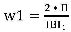
[000341] IBI1은 다른 동맥 펄스의 심장 시간 기간이다. [000341] IBI 1 is the cardiac time period of another arterial pulse.
[000342] PP2는 MAP2를 갖는 특정 동맥 펄스에 대한 PP의 추정이다. [000342] PP2 is an estimate of PP for a specific arterial pulse with MAP2.
(40) 
[000343] MAP2는 위의 맵(map) 추적 방법에 따라 추정되며;[000343] MAP2 is estimated according to the above map tracking method;
[000344] 
[000345] IBI2는 특정 동맥 펄스의 심장 시간 기간이다. [000345] IBI 2 is the cardiac time period of a particular arterial pulse.
[000346] 도 15와 관련되지 않은 상이한 실시예들에서, 프로세싱 시스템은 다음의 관계를 가정하여 PP2를 계산할 수 있다:[000346] In different embodiments not related to FIG. 15, the processing system may calculate PP2 assuming the following relationship:
(41) 
[000348] 도 16은 피험자의 심장 SV들에 대한 동맥 펄스 트레인들 및 시간 대응; 및 델타 함수들을 도시한다. 16 shows arterial pulse trains and time correspondence for heart SVs of a subject; And delta functions.
[000349] 도 16은 트레이스들(1601, 1602) 및 델타 함수들(1603); 마커(1604); 및 시간 차이 deltaT(1605)를 도시한다. 16 shows traces 1601 and 1602 and
[000350] 트레이스(1601)는 시간에 대한 결과적인 동맥 혈압을 도시한다. 트레이스(1602)는 시간에 대한 심장 혈류를 표현한다. 델타 함수들의 크기들(1603)은 각각의 확장기 페이즈의 종료와 동일한 시간들에서의 심장 일회박출량에 대한 값들을 표현한다. 마커(1604)는 프로세싱 시스템이 추적 센서 데이터로부터 심장 주기들의 시작인 것으로 결정하는 시간들을 식별한다. 마커 지점들(1604)은 캘리브레이션의 제4 단계: "추적 센서 데이터의 프로세싱"에서 앞서 설명된 바와 같은 특징적인 특징들로부터 식별될 수 있다. 시간 차이(1605)는 확장기 종료와 마커 포인트(1604) 사이의 시간 deltaT를 식별한다. [000350]
[000351] 심혈관 시스템에 대한 관련 프로세싱[000351] Related processing for the cardiovascular system
[000352] 프로세싱 시스템은 도 16에 도시된 데이터를 사용하여 심장 주기들의 시작 및 종료 시간들을 결정한다. 프로세싱 시스템은 위의 SV 추정의 논의에서 설명된 바와 같이 심장 주기들의 SV들 및 deltaT에 대한 하나의 값을 결정하기 위해 심장 주기 시작 및 종료 시간들, 트레이스(1601) 및 특정 심혈관 모델을 사용한다. [000352] The processing system uses the data shown in FIG. 16 to determine the start and end times of the cardiac cycles. The processing system uses the cardiac cycle start and end times,
[000353] 위에서 설명된 SV 추정 프로세스는 이 특정 심혈관 모델에 기초한다. 이 심혈관 모델은 시간에 대한 심장 혈류가 심장 함수 xh(t)와의, 1603에 도시된 일련의 가변 진폭 델타 함수들의 콘볼루션(convolution)이라고 가정한다. 예컨대, xh(t)는 방정식(31)의 푸리에 변환의 인수에 의해 정의될 수 있으며, 이는:[000353] The SV estimation process described above is based on this particular cardiovascular model. This cardiovascular model assumes that the cardiac blood flow over time is a convolution of the series of variable amplitude delta functions shown in 1603 with the cardiac function xh(t). For example, xh(t) can be defined by the factor of the Fourier transform of equation (31), which is:
(42) 
[000354] 시간에 대한 hbf(Heart Blood Flow)의 푸리에 변환은 다음과 같다:[000354] Fourier transform of hbf (Heart Blood Flow) with respect to time is as follows:
(43) 
[000355] Xh(w)는 방정식(31)으로부터 취해지고;[000355] Xh(w) is taken from equation (31);
[000356] SVi는 i = 0, ..., N-1 일회박출량들의 일회박출량 SV이다. [000356] SVi is i = 0, ..., N-1 stroke amount SV of the stroke amount.
[000357] S =j*w; 및[000357] S =j*w; And
[000358] ti는 델타 함수들의 임펄스 i의 인스턴스들이다. [000358] t i are instances of impulse i of delta functions.
[000359] 시간에 대한 동맥 혈압은 도 8의 부하(802); 2-포트 네트워크(803) 및 추적 센서(805)를 포함하는 대응하는 결합된 전기 모델의 임펄스 응답과의 hbf의 다른 콘볼루션일뿐이다. [000359] Arterial blood pressure versus time is the
[000360] 주파수 도메인에서, 이는 다음과 같이 방정식(29)으로 표현될 수 있다:[000360] In the frequency domain, this can be expressed by equation (29) as follows:
(44) 
[000361] 여기서 Hsys(w)는 다음과 같이 정의된다:[000361] Here Hsys(w) is defined as follows:
(45) 
[000362] 그리고, 이에 따라 센서에 의해 측정된 바와 같은 신호 Y(w)의 스펙트럼에 일회박출량을 연결하는 방정식들은 다음과 같다:And, accordingly, the equations connecting the stroke amount to the spectrum of the signal Y(w) as measured by the sensor are as follows:
(46) 
[000363] Y(w) 및 Hsys(ωw)는 둘 모두는, 미지의 SV의 길이와 동일한 길이를 갖는 일련의 값들, 바람직하게는, 복소수인 벡터들이며, 미지의 SV는 또한, 바람직하게는 실수인 값들의 리스트인 벡터이다. 따라서 방정식(46)은 다음과 같이 재작성될 수 있다:[000363] Y(w) and Hsys(ωw) are both a series of values having a length equal to the length of the unknown SV, preferably, vectors that are complex, and the unknown SV is also, preferably a real number It is a vector that is a list of phosphorus values. Thus, equation (46) can be rewritten as follows:
(47) 
[000364] 방정식(47)은 행렬 표기법에서 다음과 같을 수 있다:[000364] Equation (47) can be as follows in matrix notation:
(48) 
(49) 
(50) 
[000365] L은 시간 시프트를 표현하는 대각 행렬이고, [000365] L is a diagonal matrix representing a time shift,

[000367] SV는 실제 SV 값들의 어레이이고, Hsys는 방정식(45)에 정의된 바와 같으며, Y(w)는 출력에서의 측정된 신호이다. SV is an array of actual SV values, Hsys is as defined in equation (45), and Y(w) is the measured signal at the output.
[000368] 시스템 차원 N은 분석될 세그먼트 내의 동맥 펄스들의 수이다. 이는 또한, 분석을 수행할 주파수들의 수이다. [000368] The system dimension N is the number of arterial pulses in the segment to be analyzed. This is also the number of frequencies to perform the analysis on.
[000369] 그러나 N개의 복소수 방정식들 및 N + 1개의 실수의 미지수들이 있다. 이들은 N 차원 실벡터 SV 및 실수 값들 deltaT이다. However, there are N complex equations and N + 1 real unknowns. These are the N-dimensional real vector SV and real values deltaT.
[000370] SV에 대한 연립 방정식을 풀기 위해, 최소화 알고리즘 예컨대 L-BFGS-B을 사용하여, 에러 함수: [000370] To solve the system of equations for SV, using a minimization algorithm such as L-BFGS-B, the error function:
(51) 
[000371] 일 실시예에서, 방정식(48)에 대한 해법은 다음과 같다:[000371] In one embodiment, the solution to equation 48 is as follows:
(52) 
[000372] 주파수 도메인 신호가 정수개의 동맥 펄스들을 갖는 아날로그 신호에 대해 DFT로부터 발생함에 따라, N개의 주파수들은 균등하게 걸쳐있게 될 것인데, 
[000373] 최상의 품질 추정을 위해, 해법을 위해 사용할 N개의 주파수들은 신호가 가장 강한 곳에 있어야 하고, 이는 분석된 세그먼트의 평균 심박수 주파수 주위에서 발생한다. 이 평균 주파수 주위의 N개의 주파수들이 요구되므로, 주파수들 
[000374] 분석은 미지의 SV를 풀기 위해 심혈관 시스템의 모델 [Hsys]를 사용하지만, 실제 결과들은 [Hsys]의 정확한 값들에 둔감하다는 것이 주의되어야 한다. 따라서, 이 모델의 값들에 대한 충분한 교육된 추측들조차도, SV의 양호한 품질 추정을 달성하기에 충분하다. [000374] The analysis uses a model of the cardiovascular system [Hsys] to solve the unknown SV, but it should be noted that the actual results are insensitive to the exact values of [Hsys]. Thus, even enough educated guesses on the values of this model are sufficient to achieve a good quality estimate of the SV.
[000375] SV들 또는 혈압, 또는 이 둘 모두의 비들을 추정하기 위한 시스템은, [000375] A system for estimating the ratios of SVs or blood pressure, or both,
[000376] 프로세싱 유닛 및 메모리를 포함하는 프로세싱 시스템을 포함하고;A processing system including a processing unit and a memory;
[000377] 프로세싱 시스템은 캘리브레이션 센서로부터 캘리브레이션 센서 데이터를 수신하도록 설계되고;[000377] The processing system is designed to receive calibration sensor data from a calibration sensor;
[000378] 프로세싱 시스템은 추적 센서로부터 추적 센서 데이터를 수신하도록 설계되고;[000378] The processing system is designed to receive tracking sensor data from the tracking sensor;
[000379] 프로세싱 시스템은 캘리브레이션 센서 데이터 및 추적 센서 데이터의 함수에 기초하여 정규화 값을 결정하도록 설계되고;[000379] The processing system is designed to determine a normalization value based on a function of calibration sensor data and tracking sensor data;
[000380] 그리고[000380] and
[000381] 프로세싱 시스템은 추적 센서 데이터의 적어도 하나의 고조파 값을 정규화 값으로 나누도록 설계된다. [000381] The processing system is designed to divide at least one harmonic value of the tracking sensor data by a normalized value.
Claims (2)
프로세싱 유닛 및 메모리를 포함하는 프로세싱 시스템을 포함하고,
상기 프로세싱 시스템은 피험자로부터 획득된 캘리브레이션 센서 데이터로부터 적어도 MAP, PP, Ps 및 Pd에 대한 캘리브레이션 값을 결정하도록 설계되고;
상기 프로세싱 시스템은, MAP; PP; 및 상기 피험자로부터 획득된 추적 센서 데이터의 DFT의 고조파의 값을 포함하는 변수들의 함수로부터 FSUB 값을 계산하도록 설계되고;
상기 프로세싱 시스템은 상기 FSUB 값 및 상기 캘리브레이션 값을 사용하여 적어도 하나의 혈역학적 파라미터의 혈역학적 값들을 계산하도록 설계되고; 그리고 상기 프로세싱 시스템은 상기 계산된 혈역학적 값들을 저장 또는 송신하도록 설계되는,
피험자의 혈역학적 파라미터들의 값들을 추정하기 위한 시스템.As a system for estimating the values of the subject's hemodynamic parameters,
A processing system including a processing unit and a memory,
The processing system is designed to determine calibration values for at least MAP, PP, Ps and Pd from calibration sensor data obtained from a subject;
The processing system includes: MAP; PP; And calculating the FSUB value from a function of variables including the value of the harmonic of the DFT of the tracking sensor data obtained from the subject;
The processing system is designed to calculate hemodynamic values of at least one hemodynamic parameter using the FSUB value and the calibration value; And the processing system is designed to store or transmit the calculated hemodynamic values,
A system for estimating values of a subject's hemodynamic parameters.
상기 프로세싱 시스템이 피험자로부터 획득된 캘리브레이션 센서 데이터로부터 적어도 MAP, PP, Ps 및 Pd에 대한 캘리브레이션 값을 결정하는 단계;
상기 프로세싱 시스템이 MAP; PP; 및 상기 피험자로부터 획득된 추적 센서 데이터의 DFT의 고조파의 값을 포함하는 변수들의 함수로부터 FSUB 값을 계산하는 단계;
상기 프로세싱 시스템이 상기 FSUB 값 및 상기 캘리브레이션 값을 사용하여 적어도 하나의 혈역학적 파라미터의 혈역학적 값들을 계산하는 단계; 및
상기 프로세싱 시스템이 상기 계산된 혈역학적 값들을 저장 또는 송신하는 단계를 포함하는,
피험자의 혈역학적 파라미터들의 값들을 추정하기 위한 방법.
A method for estimating values of hemodynamic parameters of a subject comprising using a system comprising a processing system comprising a processing unit and a memory,
Determining, by the processing system, calibration values for at least MAP, PP, Ps, and Pd from calibration sensor data obtained from a subject;
The processing system includes MAP; PP; And calculating an FSUB value from a function of variables including a harmonic value of DFT of the tracking sensor data obtained from the subject.
Calculating, by the processing system, hemodynamic values of at least one hemodynamic parameter using the FSUB value and the calibration value; And
Storing or transmitting the calculated hemodynamic values by the processing system,
A method for estimating the values of a subject's hemodynamic parameters.
Applications Claiming Priority (3)
| Application Number | Priority Date | Filing Date | Title |
|---|---|---|---|
| US201762609435P | 2017-12-22 | 2017-12-22 | |
| US62/609,435 | 2017-12-22 | ||
| PCT/US2018/067412 WO2019126813A1 (en) | 2017-12-22 | 2018-12-22 | Continuous blood pressure measurement |
Related Parent Applications (1)
| Application Number | Title | Priority Date | Filing Date |
|---|---|---|---|
| KR1020207018036A Division KR20200105659A (en) | 2017-12-22 | 2018-12-22 | Continuous blood pressure measurement |
Publications (1)
| Publication Number | Publication Date |
|---|---|
| KR20200097802A true KR20200097802A (en) | 2020-08-19 |
Family
ID=66995134
Family Applications (4)
| Application Number | Title | Priority Date | Filing Date |
|---|---|---|---|
| KR1020207018036A Ceased KR20200105659A (en) | 2017-12-22 | 2018-12-22 | Continuous blood pressure measurement |
| KR1020207021477A Ceased KR20200097802A (en) | 2017-12-22 | 2018-12-22 | Continuous blood pressure measurement |
| KR1020207021476A Ceased KR20200097801A (en) | 2017-12-22 | 2018-12-22 | Continuous blood pressure measurement |
| KR1020207021481A Abandoned KR20200097803A (en) | 2017-12-22 | 2018-12-22 | Continuous blood pressure measurement |
Family Applications Before (1)
| Application Number | Title | Priority Date | Filing Date |
|---|---|---|---|
| KR1020207018036A Ceased KR20200105659A (en) | 2017-12-22 | 2018-12-22 | Continuous blood pressure measurement |
Family Applications After (2)
| Application Number | Title | Priority Date | Filing Date |
|---|---|---|---|
| KR1020207021476A Ceased KR20200097801A (en) | 2017-12-22 | 2018-12-22 | Continuous blood pressure measurement |
| KR1020207021481A Abandoned KR20200097803A (en) | 2017-12-22 | 2018-12-22 | Continuous blood pressure measurement |
Country Status (5)
| Country | Link |
|---|---|
| US (3) | US11406273B2 (en) |
| EP (1) | EP3742963A4 (en) |
| KR (4) | KR20200105659A (en) |
| CN (4) | CN111671410A (en) |
| WO (1) | WO2019126813A1 (en) |
Families Citing this family (11)
| Publication number | Priority date | Publication date | Assignee | Title |
|---|---|---|---|---|
| EP3742963A4 (en) | 2017-12-22 | 2022-04-20 | Sensifree Ltd. | CONTINUOUS BLOOD PRESSURE MEASUREMENT |
| CN112438712A (en) * | 2019-08-30 | 2021-03-05 | 南京理工大学 | Non-contact blood pressure variability real-time measurement system, computer device and storage medium |
| US11786133B2 (en) | 2020-12-18 | 2023-10-17 | Movano Inc. | System for monitoring a health parameter of a person utilizing a pulse wave signal |
| US11883134B2 (en) | 2020-12-18 | 2024-01-30 | Movano Inc. | System for monitoring a physiological parameter in a person that involves coherently combining data generated from an RF-based sensor system |
| US11832919B2 (en) | 2020-12-18 | 2023-12-05 | Movano Inc. | Method for generating training data for use in monitoring the blood pressure of a person that utilizes a pulse wave signal generated from radio frequency scanning |
| US12121336B2 (en) | 2020-12-18 | 2024-10-22 | Movano Inc. | Method for monitoring a physiological parameter in a person that involves coherently combining data generated from an RF-based sensor system |
| US11864861B2 (en) | 2020-12-18 | 2024-01-09 | Movano Inc. | Method for monitoring a physiological parameter in a person that involves spectral agility |
| IL309106A (en) * | 2021-06-17 | 2024-02-01 | Baropace Inc | Systems and methods for calibrating blood pressure devices |
| WO2023016326A1 (en) * | 2021-08-07 | 2023-02-16 | 广东乐心医疗电子股份有限公司 | Blood pressure calibration method and apparatus, blood pressure measurement system, and electronic device |
| CN114176546B (en) * | 2021-08-07 | 2022-12-09 | 广东乐心医疗电子股份有限公司 | Blood pressure measuring device and electronic apparatus |
| US12575744B2 (en) * | 2022-05-13 | 2026-03-17 | Hon Hai Precision Industry Co., Ltd. | Data processing device and method |
Family Cites Families (48)
| Publication number | Priority date | Publication date | Assignee | Title |
|---|---|---|---|---|
| JPS6214831A (en) * | 1985-07-12 | 1987-01-23 | 松下電工株式会社 | Electronic hemomanometer |
| US5211177A (en) * | 1990-12-28 | 1993-05-18 | Regents Of The University Of Minnesota | Vascular impedance measurement instrument |
| US5101828A (en) * | 1991-04-11 | 1992-04-07 | Rutgers, The State University Of Nj | Methods and apparatus for nonivasive monitoring of dynamic cardiac performance |
| WO1994015526A1 (en) * | 1993-01-07 | 1994-07-21 | Seiko Epson Corporation | Pulse wave analyzer, and diagnosis apparatus using the same |
| US5579776A (en) | 1995-01-13 | 1996-12-03 | Johnson & Johnson Medical, Inc. | Oscillometric blood pressure monitor with enhanced cuff pressure control |
| AUPN179895A0 (en) * | 1995-03-17 | 1995-04-13 | Pwv Medical Pty Ltd | Non-invasive determination of aortic flow velocity waveforms |
| US5928155A (en) | 1997-01-24 | 1999-07-27 | Cardiox Corporation | Cardiac output measurement with metabolizable analyte containing fluid |
| WO1999009884A1 (en) * | 1997-08-26 | 1999-03-04 | Seiko Epson Corporation | Measuring, sensing, and diagnosing apparatus and method relating to wave pulse, cardiac function, and, motion intensity |
| JP4571317B2 (en) | 1999-06-01 | 2010-10-27 | マサチューセッツ インスティテュート オブ テクノロジー | Pressureless continuous blood pressure monitoring device |
| US6471655B1 (en) * | 1999-06-29 | 2002-10-29 | Vitalwave Corporation | Method and apparatus for the noninvasive determination of arterial blood pressure |
| WO2003034916A2 (en) * | 2001-08-17 | 2003-05-01 | Russell Ted W | Methods, apparatus and sensor for hemodynamic monitoring |
| US7422562B2 (en) * | 2003-12-05 | 2008-09-09 | Edwards Lifesciences | Real-time measurement of ventricular stroke volume variations by continuous arterial pulse contour analysis |
| US7220230B2 (en) * | 2003-12-05 | 2007-05-22 | Edwards Lifesciences Corporation | Pressure-based system and method for determining cardiac stroke volume |
| US7569015B2 (en) | 2005-07-15 | 2009-08-04 | General Electric Company | Integrated physiology and imaging workstation |
| CN100496388C (en) * | 2005-08-31 | 2009-06-10 | 深圳迈瑞生物医疗电子股份有限公司 | Device for calculating blood pressure by using signal transformation |
| CA2655049A1 (en) | 2006-05-13 | 2007-11-22 | Tensys Medical, Inc. | Continuous positioning apparatus and methods |
| US8905939B2 (en) * | 2006-07-13 | 2014-12-09 | Edwards Lifesciences Corporation | Method and apparatus for continuous assessment of a cardiovascular parameter using the arterial pulse pressure propagation time and waveform |
| US8162841B2 (en) * | 2007-08-31 | 2012-04-24 | Pacesetter, Inc. | Standalone systemic arterial blood pressure monitoring device |
| WO2009043028A2 (en) * | 2007-09-28 | 2009-04-02 | Tiax Llc | Measurement of physiological signals |
| KR100978902B1 (en) * | 2008-05-29 | 2010-08-31 | 명지대학교 산학협력단 | Fourier Transform-Based Phase Estimation Method and Apparatus Eliminating Exponential Attenuation of DC Offset |
| US9687161B2 (en) * | 2008-09-30 | 2017-06-27 | Nellcor Puritan Bennett Ireland | Systems and methods for maintaining blood pressure monitor calibration |
| US8491487B2 (en) | 2009-02-11 | 2013-07-23 | Edwards Lifesciences Corporation | Detection of parameters in cardiac output related waveforms |
| GB0904435D0 (en) | 2009-03-13 | 2009-04-29 | King David H | Haemodynamic data estimation |
| JP5410210B2 (en) * | 2009-09-08 | 2014-02-05 | 日本光電工業株式会社 | Artifact removal method, blood volume measuring device and artifact removal program in respiratory stroke fluctuation analysis device for stroke volume |
| US20170224232A1 (en) * | 2009-12-08 | 2017-08-10 | Medical Screening Corporation | Measuring homeostatic risk |
| US8740803B2 (en) * | 2010-03-23 | 2014-06-03 | General Electric Company | Use of the frequency spectrum of artifact in oscillometry |
| US20130085355A1 (en) * | 2011-09-30 | 2013-04-04 | University Of Limerick | Monitoring system |
| CN103099610B (en) * | 2011-11-11 | 2015-05-13 | 杭州电子科技大学 | Ambulatory blood pressure measuring device and method based on pulse wave transmission time difference of left brachial artery and right brachial artery |
| US8926520B2 (en) | 2012-07-20 | 2015-01-06 | Endophys Holdings, Llc | Transducer interface system and method |
| CA2798337A1 (en) * | 2012-12-04 | 2014-06-04 | University Of Winnipeg | Cardiovascular pulse wave analysis method and system |
| WO2014107769A1 (en) * | 2013-01-14 | 2014-07-17 | Uscom Limited | Combined blood flow and pressure monitoring system and method |
| CN103070678A (en) * | 2013-02-21 | 2013-05-01 | 沈阳恒德医疗器械研发有限公司 | Non-invasive central arterial pressure detector and detection method thereof |
| AU2014316960A1 (en) | 2013-09-09 | 2016-03-10 | Gambro Lundia Ab | Separation of interference pulses from physiological pulses in a pressure signal |
| US10285606B2 (en) * | 2013-12-13 | 2019-05-14 | Quantium Medical S.L. | Methods and apparatus for the on-line and real time acquisition and analysis of voltage plethysmography, electrocardiogram and electroencephalogram for the estimation of stroke volume, cardiac output, and systemic inflammation |
| CN103860180B (en) | 2013-12-16 | 2016-03-02 | 中国医学科学院北京协和医院 | In cardio-pulmonary resuscitation (CPR) process, Real time identification spontaneous circulation recovers (ROSC) |
| DE112014006082T5 (en) * | 2013-12-25 | 2016-10-27 | Asahi Kasei Kabushiki Kaisha | Pulse wave measuring device, mobile device, medical equipment system and biological information communication system |
| EP3182889B1 (en) * | 2014-08-22 | 2023-12-20 | Sotera Wireless, Inc. | Method for calibrating a blood pressure measurement based on vascular transit of a pulse wave |
| US20170238816A1 (en) * | 2014-10-20 | 2017-08-24 | Hamamatsu Photonics K.K. | Blood pressure measurement method, blood pressure measurement device, blood pressure measurement program, and recording medium for recording said program |
| JP6366463B2 (en) * | 2014-10-31 | 2018-08-01 | オムロンヘルスケア株式会社 | Blood pressure measurement device |
| US10856743B2 (en) * | 2015-08-28 | 2020-12-08 | Oslermd, Inc. | Methods and apparatuses for measuring multiple vital signs based on arterial pressure waveforms |
| CN105725998B (en) * | 2015-11-05 | 2018-08-17 | 香港应用科技研究院有限公司 | System for Blood Pressure Measurement Using Mental State Verification |
| WO2017197120A1 (en) * | 2016-05-11 | 2017-11-16 | University Of Maryland, Baltimore | Method and apparatus for predicting a use for a blood transfusion |
| JP2017216669A (en) | 2016-05-26 | 2017-12-07 | パナソニックIpマネジメント株式会社 | Amplifier circuit and pulse wave measurement apparatus |
| CN106539572A (en) * | 2016-11-02 | 2017-03-29 | 中国科学院电子学研究所 | A kind of continuity blood pressure measuring method of multi-parameter fusion |
| CN106691406A (en) * | 2017-01-05 | 2017-05-24 | 大连理工大学 | Detection method of vascular elasticity and blood pressure based on single probe photoplethysmography pulse wave |
| US10667701B1 (en) * | 2017-02-03 | 2020-06-02 | University Of South Florida | Systems and methods for determining physiological parameters from blood flow dynamics |
| WO2019010416A1 (en) * | 2017-07-06 | 2019-01-10 | Caretaker Medical Llc | Self-calibrating systems and methods for blood pressure wave form analysis and diagnostic support |
| EP3742963A4 (en) | 2017-12-22 | 2022-04-20 | Sensifree Ltd. | CONTINUOUS BLOOD PRESSURE MEASUREMENT |
-
2018
- 2018-12-22 EP EP18892075.5A patent/EP3742963A4/en not_active Withdrawn
- 2018-12-22 KR KR1020207018036A patent/KR20200105659A/en not_active Ceased
- 2018-12-22 CN CN202010551377.1A patent/CN111671410A/en active Pending
- 2018-12-22 US US16/758,012 patent/US11406273B2/en active Active
- 2018-12-22 CN CN201880076278.3A patent/CN111417340A/en active Pending
- 2018-12-22 KR KR1020207021477A patent/KR20200097802A/en not_active Ceased
- 2018-12-22 CN CN202010551492.9A patent/CN111671411A/en active Pending
- 2018-12-22 WO PCT/US2018/067412 patent/WO2019126813A1/en not_active Ceased
- 2018-12-22 KR KR1020207021476A patent/KR20200097801A/en not_active Ceased
- 2018-12-22 KR KR1020207021481A patent/KR20200097803A/en not_active Abandoned
- 2018-12-22 CN CN202010553055.0A patent/CN111671412A/en active Pending
-
2020
- 2020-04-23 US US16/857,001 patent/US20200268254A1/en not_active Abandoned
- 2020-04-23 US US16/856,927 patent/US20200245877A1/en not_active Abandoned
Also Published As
| Publication number | Publication date |
|---|---|
| EP3742963A1 (en) | 2020-12-02 |
| CN111417340A (en) | 2020-07-14 |
| KR20200097803A (en) | 2020-08-19 |
| CN111671411A (en) | 2020-09-18 |
| CN111671410A (en) | 2020-09-18 |
| US20200315471A1 (en) | 2020-10-08 |
| KR20200097801A (en) | 2020-08-19 |
| WO2019126813A1 (en) | 2019-06-27 |
| KR20200105659A (en) | 2020-09-08 |
| US20200268254A1 (en) | 2020-08-27 |
| US11406273B2 (en) | 2022-08-09 |
| CN111671412A (en) | 2020-09-18 |
| US20200245877A1 (en) | 2020-08-06 |
| EP3742963A4 (en) | 2022-04-20 |
Similar Documents
| Publication | Publication Date | Title |
|---|---|---|
| US11406273B2 (en) | Continuous blood pressure measurement | |
| US7220230B2 (en) | Pressure-based system and method for determining cardiac stroke volume | |
| US20200253564A1 (en) | Continuous Blood Pressure Measurement | |
| CN107530005B (en) | Method and apparatus for deriving mean arterial pressure of a subject | |
| Kurylyak et al. | A Neural Network-based method for continuous blood pressure estimation from a PPG signal | |
| US11864874B2 (en) | Method, apparatus and computer program for determining a blood pressure value | |
| US9060695B2 (en) | Systems and methods for determining differential pulse transit time from the phase difference of two analog plethysmographs | |
| KR100871230B1 (en) | Non-invasive, non-invasive wrist blood pressure measurement method and apparatus that interoperate with a communication device | |
| US20050124904A1 (en) | Arterial pressure-based, automatic determination of a cardiovascular parameter | |
| JP2012505679A (en) | System and apparatus for non-invasive measurement of blood pressure | |
| US20250040814A1 (en) | Device, system and method for calibrating a blood pressure surrogate for use in monitoring a subject's blood pressure | |
| US20250221628A1 (en) | Device, system and method for calibrating a blood pressure surrogate for use in monitoring a subject's blood pressure | |
| KR102272019B1 (en) | Blood Pressure Meter And Method For Measuring Blood Pressure Using The Same | |
| Mouradian et al. | Noninvasive continuous mobile blood pressure monitoring using novel PPG optical sensor | |
| Singha et al. | Noninvasive heart rate and blood glucose level estimation using photoplethysmography | |
| KR102622935B1 (en) | Medical apparatus | |
| Islam et al. | Design and implementation of non-invasive continuous blood pressure measurement and monitoring system using photoplethysmography | |
| CN115990007B (en) | Central arterial pressure waveform fitting method, monitoring device and watch equipment | |
| US7497832B2 (en) | Method and device for measuring peripheral vascular function | |
| GB2404439A (en) | Method of measuring a person's aortic blood pressure |
Legal Events
| Date | Code | Title | Description |
|---|---|---|---|
| A107 | Divisional application of patent | ||
| PA0104 | Divisional application for international application |
Comment text: Divisional Application for International Patent Patent event code: PA01041R01D Patent event date: 20200723 Application number text: 1020207018036 Filing date: 20200622 |
|
| PG1501 | Laying open of application | ||
| A201 | Request for examination | ||
| PA0201 | Request for examination |
Patent event code: PA02012R01D Patent event date: 20211123 Comment text: Request for Examination of Application |
|
| E902 | Notification of reason for refusal | ||
| PE0902 | Notice of grounds for rejection |
Comment text: Notification of reason for refusal Patent event date: 20230619 Patent event code: PE09021S01D |
|
| E601 | Decision to refuse application | ||
| PE0601 | Decision on rejection of patent |
Patent event date: 20230823 Comment text: Decision to Refuse Application Patent event code: PE06012S01D Patent event date: 20230619 Comment text: Notification of reason for refusal Patent event code: PE06011S01I |