KR20200098643A - 전동기, 압축기, 송풍기, 및 냉동 공조 장치 - Google Patents
전동기, 압축기, 송풍기, 및 냉동 공조 장치 Download PDFInfo
- Publication number
- KR20200098643A KR20200098643A KR1020207020478A KR20207020478A KR20200098643A KR 20200098643 A KR20200098643 A KR 20200098643A KR 1020207020478 A KR1020207020478 A KR 1020207020478A KR 20207020478 A KR20207020478 A KR 20207020478A KR 20200098643 A KR20200098643 A KR 20200098643A
- Authority
- KR
- South Korea
- Prior art keywords
- rotor
- electric motor
- end plate
- stator
- axial direction
- Prior art date
- Legal status (The legal status is an assumption and is not a legal conclusion. Google has not performed a legal analysis and makes no representation as to the accuracy of the status listed.)
- Granted
Links
Images


Classifications
-
- H—ELECTRICITY
- H02—GENERATION; CONVERSION OR DISTRIBUTION OF ELECTRIC POWER
- H02K—DYNAMO-ELECTRIC MACHINES
- H02K1/00—Details of the magnetic circuit
- H02K1/06—Details of the magnetic circuit characterised by the shape, form or construction
- H02K1/22—Rotating parts of the magnetic circuit
- H02K1/27—Rotor cores with permanent magnets
- H02K1/2706—Inner rotors
- H02K1/272—Inner rotors the magnetisation axis of the magnets being perpendicular to the rotor axis
- H02K1/274—Inner rotors the magnetisation axis of the magnets being perpendicular to the rotor axis the rotor consisting of two or more circumferentially positioned magnets
- H02K1/2753—Inner rotors the magnetisation axis of the magnets being perpendicular to the rotor axis the rotor consisting of two or more circumferentially positioned magnets the rotor consisting of magnets or groups of magnets arranged with alternating polarity
- H02K1/276—Magnets embedded in the magnetic core, e.g. interior permanent magnets [IPM]
-
- H—ELECTRICITY
- H02—GENERATION; CONVERSION OR DISTRIBUTION OF ELECTRIC POWER
- H02K—DYNAMO-ELECTRIC MACHINES
- H02K1/00—Details of the magnetic circuit
- H02K1/06—Details of the magnetic circuit characterised by the shape, form or construction
- H02K1/22—Rotating parts of the magnetic circuit
- H02K1/27—Rotor cores with permanent magnets
- H02K1/2706—Inner rotors
- H02K1/272—Inner rotors the magnetisation axis of the magnets being perpendicular to the rotor axis
- H02K1/274—Inner rotors the magnetisation axis of the magnets being perpendicular to the rotor axis the rotor consisting of two or more circumferentially positioned magnets
- H02K1/2753—Inner rotors the magnetisation axis of the magnets being perpendicular to the rotor axis the rotor consisting of two or more circumferentially positioned magnets the rotor consisting of magnets or groups of magnets arranged with alternating polarity
-
- H—ELECTRICITY
- H02—GENERATION; CONVERSION OR DISTRIBUTION OF ELECTRIC POWER
- H02K—DYNAMO-ELECTRIC MACHINES
- H02K7/00—Arrangements for handling mechanical energy structurally associated with dynamo-electric machines, e.g. structural association with mechanical driving motors or auxiliary dynamo-electric machines
- H02K7/14—Structural association with mechanical loads, e.g. with hand-held machine tools or fans
-
- F—MECHANICAL ENGINEERING; LIGHTING; HEATING; WEAPONS; BLASTING
- F04—POSITIVE - DISPLACEMENT MACHINES FOR LIQUIDS; PUMPS FOR LIQUIDS OR ELASTIC FLUIDS
- F04B—POSITIVE-DISPLACEMENT MACHINES FOR LIQUIDS; PUMPS
- F04B39/00—Component parts, details, or accessories, of pumps or pumping systems specially adapted for elastic fluids, not otherwise provided for in, or of interest apart from, groups F04B25/00 - F04B37/00
-
- F—MECHANICAL ENGINEERING; LIGHTING; HEATING; WEAPONS; BLASTING
- F24—HEATING; RANGES; VENTILATING
- F24F—AIR-CONDITIONING; AIR-HUMIDIFICATION; VENTILATION; USE OF AIR CURRENTS FOR SCREENING
- F24F1/00—Room units for air-conditioning, e.g. separate or self-contained units or units receiving primary air from a central station
- F24F1/0007—Indoor units, e.g. fan coil units
- F24F1/00073—Indoor units, e.g. fan coil units comprising a compressor in the indoor unit housing
-
- F—MECHANICAL ENGINEERING; LIGHTING; HEATING; WEAPONS; BLASTING
- F25—REFRIGERATION OR COOLING; COMBINED HEATING AND REFRIGERATION SYSTEMS; HEAT PUMP SYSTEMS; MANUFACTURE OR STORAGE OF ICE; LIQUEFACTION SOLIDIFICATION OF GASES
- F25B—REFRIGERATION MACHINES, PLANTS OR SYSTEMS; COMBINED HEATING AND REFRIGERATION SYSTEMS; HEAT PUMP SYSTEMS
- F25B31/00—Compressor arrangements
- F25B31/02—Compressor arrangements of motor-compressor units
-
- H—ELECTRICITY
- H02—GENERATION; CONVERSION OR DISTRIBUTION OF ELECTRIC POWER
- H02K—DYNAMO-ELECTRIC MACHINES
- H02K1/00—Details of the magnetic circuit
- H02K1/06—Details of the magnetic circuit characterised by the shape, form or construction
- H02K1/12—Stationary parts of the magnetic circuit
- H02K1/14—Stator cores with salient poles
- H02K1/146—Stator cores with salient poles consisting of a generally annular yoke with salient poles
-
- H—ELECTRICITY
- H02—GENERATION; CONVERSION OR DISTRIBUTION OF ELECTRIC POWER
- H02K—DYNAMO-ELECTRIC MACHINES
- H02K1/00—Details of the magnetic circuit
- H02K1/06—Details of the magnetic circuit characterised by the shape, form or construction
- H02K1/12—Stationary parts of the magnetic circuit
- H02K1/16—Stator cores with slots for windings
-
- H—ELECTRICITY
- H02—GENERATION; CONVERSION OR DISTRIBUTION OF ELECTRIC POWER
- H02K—DYNAMO-ELECTRIC MACHINES
- H02K1/00—Details of the magnetic circuit
- H02K1/06—Details of the magnetic circuit characterised by the shape, form or construction
- H02K1/22—Rotating parts of the magnetic circuit
- H02K1/27—Rotor cores with permanent magnets
- H02K1/2706—Inner rotors
- H02K1/272—Inner rotors the magnetisation axis of the magnets being perpendicular to the rotor axis
- H02K1/274—Inner rotors the magnetisation axis of the magnets being perpendicular to the rotor axis the rotor consisting of two or more circumferentially positioned magnets
- H02K1/2753—Inner rotors the magnetisation axis of the magnets being perpendicular to the rotor axis the rotor consisting of two or more circumferentially positioned magnets the rotor consisting of magnets or groups of magnets arranged with alternating polarity
- H02K1/278—Surface mounted magnets; Inset magnets
-
- H—ELECTRICITY
- H02—GENERATION; CONVERSION OR DISTRIBUTION OF ELECTRIC POWER
- H02K—DYNAMO-ELECTRIC MACHINES
- H02K1/00—Details of the magnetic circuit
- H02K1/06—Details of the magnetic circuit characterised by the shape, form or construction
- H02K1/22—Rotating parts of the magnetic circuit
- H02K1/28—Means for mounting or fastening rotating magnetic parts on to, or to, the rotor structures
-
- H—ELECTRICITY
- H02—GENERATION; CONVERSION OR DISTRIBUTION OF ELECTRIC POWER
- H02K—DYNAMO-ELECTRIC MACHINES
- H02K1/00—Details of the magnetic circuit
- H02K1/06—Details of the magnetic circuit characterised by the shape, form or construction
- H02K1/22—Rotating parts of the magnetic circuit
- H02K1/32—Rotating parts of the magnetic circuit with channels or ducts for flow of cooling medium
-
- H—ELECTRICITY
- H02—GENERATION; CONVERSION OR DISTRIBUTION OF ELECTRIC POWER
- H02K—DYNAMO-ELECTRIC MACHINES
- H02K15/00—Processes or apparatus specially adapted for manufacturing, assembling, maintaining or repairing of dynamo-electric machines
- H02K15/02—Processes or apparatus specially adapted for manufacturing, assembling, maintaining or repairing of dynamo-electric machines of stator or rotor bodies
- H02K15/03—Processes or apparatus specially adapted for manufacturing, assembling, maintaining or repairing of dynamo-electric machines of stator or rotor bodies having permanent magnets
-
- H—ELECTRICITY
- H02—GENERATION; CONVERSION OR DISTRIBUTION OF ELECTRIC POWER
- H02K—DYNAMO-ELECTRIC MACHINES
- H02K21/00—Synchronous motors having permanent magnets; Synchronous generators having permanent magnets
- H02K21/12—Synchronous motors having permanent magnets; Synchronous generators having permanent magnets with stationary armatures and rotating magnets
- H02K21/14—Synchronous motors having permanent magnets; Synchronous generators having permanent magnets with stationary armatures and rotating magnets with magnets rotating within the armatures
- H02K21/16—Synchronous motors having permanent magnets; Synchronous generators having permanent magnets with stationary armatures and rotating magnets with magnets rotating within the armatures having annular armature cores with salient poles
-
- H—ELECTRICITY
- H02—GENERATION; CONVERSION OR DISTRIBUTION OF ELECTRIC POWER
- H02K—DYNAMO-ELECTRIC MACHINES
- H02K3/00—Details of windings
- H02K3/32—Windings characterised by the shape, form or construction of the insulation
- H02K3/34—Windings characterised by the shape, form or construction of the insulation between conductors or between conductor and core, e.g. slot insulation
- H02K3/345—Windings characterised by the shape, form or construction of the insulation between conductors or between conductor and core, e.g. slot insulation between conductor and core, e.g. slot insulation
-
- H—ELECTRICITY
- H02—GENERATION; CONVERSION OR DISTRIBUTION OF ELECTRIC POWER
- H02K—DYNAMO-ELECTRIC MACHINES
- H02K3/00—Details of windings
- H02K3/46—Fastening of windings on the stator or rotor structure
- H02K3/52—Fastening salient pole windings or connections thereto
- H02K3/521—Fastening salient pole windings or connections thereto applicable to stators only
- H02K3/522—Fastening salient pole windings or connections thereto applicable to stators only for generally annular cores with salient poles
-
- H—ELECTRICITY
- H02—GENERATION; CONVERSION OR DISTRIBUTION OF ELECTRIC POWER
- H02P—CONTROL OR REGULATION OF ELECTRIC MOTORS, ELECTRIC GENERATORS OR DYNAMO-ELECTRIC CONVERTERS; CONTROLLING TRANSFORMERS, REACTORS OR CHOKE COILS
- H02P25/00—Arrangements or methods for the control of AC motors characterised by the kind of AC motor or by structural details
- H02P25/02—Arrangements or methods for the control of AC motors characterised by the kind of AC motor or by structural details characterised by the kind of motor
- H02P25/022—Synchronous motors
-
- H—ELECTRICITY
- H02—GENERATION; CONVERSION OR DISTRIBUTION OF ELECTRIC POWER
- H02P—CONTROL OR REGULATION OF ELECTRIC MOTORS, ELECTRIC GENERATORS OR DYNAMO-ELECTRIC CONVERTERS; CONTROLLING TRANSFORMERS, REACTORS OR CHOKE COILS
- H02P27/00—Arrangements or methods for the control of AC motors characterised by the kind of supply voltage
- H02P27/04—Arrangements or methods for the control of AC motors characterised by the kind of supply voltage using variable-frequency supply voltage, e.g. inverter or converter supply voltage
- H02P27/06—Arrangements or methods for the control of AC motors characterised by the kind of supply voltage using variable-frequency supply voltage, e.g. inverter or converter supply voltage using DC to AC converters or inverters
-
- H—ELECTRICITY
- H02—GENERATION; CONVERSION OR DISTRIBUTION OF ELECTRIC POWER
- H02K—DYNAMO-ELECTRIC MACHINES
- H02K2201/00—Specific aspects not provided for in the other groups of this subclass relating to the magnetic circuits
- H02K2201/03—Machines characterised by aspects of the air-gap between rotor and stator
-
- H—ELECTRICITY
- H02—GENERATION; CONVERSION OR DISTRIBUTION OF ELECTRIC POWER
- H02K—DYNAMO-ELECTRIC MACHINES
- H02K2213/00—Specific aspects, not otherwise provided for and not covered by codes H02K2201/00 - H02K2211/00
- H02K2213/03—Machines characterised by numerical values, ranges, mathematical expressions or similar information
-
- H—ELECTRICITY
- H02—GENERATION; CONVERSION OR DISTRIBUTION OF ELECTRIC POWER
- H02P—CONTROL OR REGULATION OF ELECTRIC MOTORS, ELECTRIC GENERATORS OR DYNAMO-ELECTRIC CONVERTERS; CONTROLLING TRANSFORMERS, REACTORS OR CHOKE COILS
- H02P2207/00—Indexing scheme relating to controlling arrangements characterised by the type of motor
- H02P2207/05—Synchronous machines, e.g. with permanent magnets or DC excitation
Landscapes
- Engineering & Computer Science (AREA)
- Power Engineering (AREA)
- General Engineering & Computer Science (AREA)
- Mechanical Engineering (AREA)
- Chemical & Material Sciences (AREA)
- Thermal Sciences (AREA)
- Physics & Mathematics (AREA)
- Combustion & Propulsion (AREA)
- Manufacturing & Machinery (AREA)
- Permanent Field Magnets Of Synchronous Machinery (AREA)
- Iron Core Of Rotating Electric Machines (AREA)
- Permanent Magnet Type Synchronous Machine (AREA)
- Control Of Multiple Motors (AREA)
- Compressor (AREA)
- Sorption Type Refrigeration Machines (AREA)
Abstract
Description
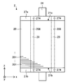
도 2는 전동기의 구조를 개략적으로 도시하는 부분 단면도.
도 3은 회전자의 구조를 개략적으로 도시하는 측면도.
도 4는 회전자의 구조를 개략적으로 도시하는 단면도.
도 5는 xz평면에서의 회전자와 고정자와의 위치 관계를 도시하는 도면.
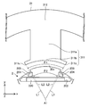
도 6은 xy평면에서의 회전자와 고정자 철심과의 위치 관계를 도시하는 도면.
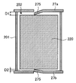
도 7은 제1 단판의 구조를 개략적으로 도시하는 평면도.
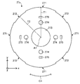
도 8은 회전자(2)의 구조를 개략적으로 도시하는 평면도.
도 9는 도 8에서의 선(C9-C9)에 따른 단면도.
도 10은 제2 단판의 다른 예를 도시하는 도면.
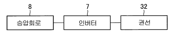
도 11은 전동기에서의 구동계의 구성의 한 예를 도시하는 블록도.
도 12는 전동기의 구동 중에서의 회전자의 상태의 한 예를 도시하는 도면.
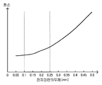
도 13은 전동기에서의 전자강판의 두께와 회전자에 생기는 철손의 크기와의 관계를 도시하는 그래프.
도 14는 본 발명의 실시의 형태 2에 관한 압축기의 구조를 개략적으로 도시하는 단면도.
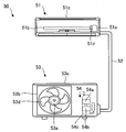
도 15는 본 발명의 실시의 형태 3에 관한 공기 조화기의 구성을 개략적으로 도시하는 도면.
2 : 회전자
3 : 고정자
4 : 축받이
6 : 압축기
8 : 승압 회로
20 : 회전자 철심
20a : 제1 부분
20b : 제2 부분
20c : 외주면(제1 외주면)
20d : 외주면(제2 외주면)
21a : 제1 회전자 단부
21b : 제2 회전자 단부
26 : 축
27a : 제1 단판
27b : 제2 단판
31 : 고정자 철심
31a : 제1 고정자 단부
31b : 제2 고정자 단부
50 : 공기 조화기
51 : 실내기(송풍기)
53 : 실외기(송풍기)
201 : 전자강판
202 : 자석 삽입구멍
220 : 영구자석
311 : 티스
311a : 본체부
311b : 티스 선단부
Claims (15)
- 축방향에서의 제1측에 있는 제1 고정자 단부와, 상기 축방향에서 상기 제1측의 반대측인 제2측에 있는 제2 고정자 단부와, 지름방향으로 연재되는 티스와, 상기 티스에 권회된 권선을 갖는 고정자와,
상기 축방향으로 적층된 복수의 전자강판, 자석 삽입구멍, 상기 제1측에 있는 제1 회전자 단부, 및 상기 제2측에 있는 제2 회전자 단부를 갖는 회전자 철심과, 상기 자석 삽입구멍에 삽입된 영구자석과, 상기 회전자 철심에 고정되어 있음과 함께 상기 제2측만으로 지지된 축과, 상기 자석 삽입구멍의 상기 제1측을 덮는 제1 단판과, 상기 자석 삽입구멍의 상기 제2측을 덮는 제2 단판을 갖는 회전자를 구비하고,
상기 제1 회전자 단부는, 상기 축방향에서 상기 제1 고정자 단부로부터 상기 제1측으로 떨어져서 위치하고 있고,
상기 제2 회전자 단부는, 상기 축방향에서 상기 제2 고정자 단부로부터 상기 제1측으로 떨어져서 위치하고 있고,
상기 영구자석부터 상기 제1 단판까지의 거리를 D1로 하고, 상기 영구자석부터 상기 제2 단판까지의 거리를 D2로 하였을 때, 상기 거리(D1) 및 상기 거리(D2)의 관계는, D1>D2≥0을 충족시키고,
상기 복수의 전자강판의 각각의 두께가 0.1㎜ 이상 0.25㎜ 이하인 것을 특징으로 하는 전동기. - 제1항에 있어서,
상기 회전자 철심은, 지름방향에서의 상기 회전자 철심의 단부이고 또한 상기 회전자의 자극 중심부에 위치하는 제1 부분과, 지름방향에서의 상기 회전자 철심의 단부이고 또한 상기 회전자의 극간부에 위치하는 제2 부분을 가지며,
상기 축방향에 직교하는 평면에서, 상기 회전자의 회전 중심부터 상기 제1 부분까지의 거리는, 상기 회전자의 상기 회전 중심부터 상기 제2 부분까지의 거리보다도 긴 것을 특징으로 하는 전동기. - 제2항에 있어서,
상기 제1 단판은, 상기 제1 단판의 외연의 일부를 형성하는 제1 외연과, 둘레방향에서 상기 제1 외연에 인접하여 있는 제2 외연을 가지며,
상기 제1 외연은, 지름방향에서 상기 제1 부분부터 내측으로 떨어져서 위치하고 있고,
상기 제2 외연은, 지름방향에서 상기 제2 부분부터 외측으로 떨어져서 위치하고 있는 것을 특징으로 하는 전동기. - 제2항 또는 제3항에 있어서,
상기 회전자 철심은, 상기 제1 부분을 포함하는 제1 외주면과, 상기 제2 부분을 포함하는 제2 외주면을 가지며,
상기 제1 외주면은, 상기 제2 외주면보다도 지름방향에서 외측으로 돌출하고 있는 것을 특징으로 하는 전동기. - 제4항에 있어서,
상기 티스는, 상기 회전자에 면하는 티스 선단부를 가지며,
상기 축방향과 직교하는 평면에서, 둘레방향에서의 상기 티스 선단부의 양단부와 상기 회전자의 회전 중심을 통과하는 2직선이 이루는 각도를 θ1으로 하고, 상기 평면에서, 상기 둘레방향에서의 상기 제1 외주면의 양단과 상기 회전자의 상기 회전 중심을 통과하는 2직선이 이루는 각도를 θ2라고 하면,
상기 전동기는 θ1≥θ2를 충족시키는 것을 특징으로 하는 전동기. - 제5항에 있어서,
상기 회전자 철심은, 지름방향에서 상기 자석 삽입구멍의 외측에 형성된 구멍을 가지며, 상기 구멍은 둘레방향으로 연재되어 있는 것을 특징으로 하는 전동기. - 제6항에 있어서,
상기 구멍은, 둘레방향에서의 상기 티스 선단부의 단부와 상기 회전자의 회전 중심을 통과하는 직선상에 위치하고 있는 것을 특징으로 하는 전동기. - 제6항 또는 제7항에 있어서,
상기 회전자 철심은, 상기 구멍과 상기 회전자 철심의 외연과의 사이에 형성된 박육부를 갖는 것을 특징으로 하는 전동기. - 제1항 내지 제8항 중 어느 한 항에 있어서,
지름방향에서의 상기 영구자석의 폭은, 상기 지름방향에서의 상기 자석 삽입구멍의 폭보다도 작고,
상기 영구자석은, 상기 자석 삽입구멍 내에서 상기 지름방향에서의 내측에 위치하고 있는 것을 특징으로 하는 전동기. - 제1항 내지 제9항 중 어느 한 항에 있어서,
상기 제1 단판은 제1 고정구멍을 가지며,
상기 회전자 철심은 제2 고정구멍을 가지며,
상기 회전자는, 상기 제1 단판을 상기 회전자 철심에 고정하는 고정부재를 가지며,
상기 고정부재는, 상기 제1 고정구멍 및 상기 제2 고정구멍에 삽입되어 있고,
상기 고정부재의 반경을 r1로 하고, 상기 제1 고정구멍의 반경을 r2로 하고, 상기 제2 고정구멍의 반경을 r3으로 하고, 상기 회전자의 자극 중심부에서의 상기 회전자 철심의 반경을 M1로 하고, 상기 자극 중심부상의 상기 제1 단판의 반경을 T1로 하였을 때,
상기 전동기는,
(r2+r3)-2×r1≤M1-T1
을 충족시키는 것을 특징으로 하는 전동기. - 제1항 내지 제10항 중 어느 한 항에 있어서,
상기 권선에 인가되는 전압을 조정하기 위한 캐리어 주파수가 1㎑부터 8㎑인 것을 특징으로 하는 전동기. - 제1항 내지 제11항 중 어느 한 항에 있어서,
상기 권선에 인가된 전압을 승압시키는 승압 회로를 또한 구비하는 것을 특징으로 하는 전동기. - 전동기와,
상기 전동기에 의해 구동되는 압축 기구와,
상기 전동기 및 상기 압축 기구를 덮는 하우징을 구비하고,
상기 전동기는,
축방향에서의 제1측에 있는 제1 고정자 단부와, 상기 축방향에서 상기 제1측의 반대측인 제2측에 있는 제2 고정자 단부와, 지름방향으로 연재되는 티스와, 상기 티스에 권회된 권선을 갖는 고정자와,
상기 축방향으로 적층된 복수의 전자강판, 자석 삽입구멍, 상기 제1측에 있는 제1 회전자 단부, 및 상기 제2측에 있는 제2 회전자 단부를 갖는 회전자 철심과, 상기 자석 삽입구멍에 삽입된 영구자석과, 상기 회전자 철심에 고정되어 있음과 함께 상기 제2측만으로 지지된 축과, 상기 자석 삽입구멍의 상기 제1측을 덮는 제1 단판과, 상기 자석 삽입구멍의 상기 제2측을 덮는 제2 단판을 갖는 회전자를 가지며,
상기 제1 회전자 단부는, 상기 축방향에서 상기 제1 고정자 단부로부터 상기 제1측으로 떨어져서 위치하고 있고,
상기 제2 회전자 단부는, 상기 축방향에서 상기 제2 고정자 단부로부터 상기 제1측으로 떨어져서 위치하고 있고,
상기 영구자석부터 상기 제1 단판까지의 거리를 D1로 하고, 상기 영구자석부터 상기 제2 단판까지의 거리를 D2로 하였을 때, 상기 거리(D1) 및 상기 거리(D2)의 관계는, D1>D2≥0을 충족시키고,
상기 복수의 전자강판의 각각의 두께가 0.1㎜ 이상 0.25㎜ 이하인 것을 특징으로 하는 압축기. - 전동기와,
상기 전동기에 의해 구동되는 날개를 구비하고,
상기 전동기는,
축방향에서의 제1측에 있는 제1 고정자 단부와, 상기 축방향에서 상기 제1측의 반대측인 제2측에 있는 제2 고정자 단부와, 지름방향으로 연재되는 티스와, 상기 티스에 권회된 권선을 갖는 고정자와,
상기 축방향으로 적층된 복수의 전자강판, 자석 삽입구멍, 상기 제1측에 있는 제1 회전자 단부, 및 상기 제2측에 있는 제2 회전자 단부를 갖는 회전자 철심과, 상기 자석 삽입구멍에 삽입된 영구자석과, 상기 회전자 철심에 고정되어 있음과 함께 상기 제2측만으로 지지된 축과, 상기 자석 삽입구멍의 상기 제1측을 덮는 제1 단판과, 상기 자석 삽입구멍의 상기 제2측을 덮는 제2 단판을 갖는 회전자를 가지며,
상기 제1 회전자 단부는, 상기 축방향에서 상기 제1 고정자 단부로부터 상기 제1측으로 떨어져서 위치하고 있고,
상기 제2 회전자 단부는, 상기 축방향에서 상기 제2 고정자 단부로부터 상기 제1측으로 떨어져서 위치하고 있고,
상기 영구자석부터 상기 제1 단판까지의 거리를 D1로 하고, 상기 영구자석부터 상기 제2 단판까지의 거리를 D2로 하였을 때, 상기 거리(D1) 및 상기 거리(D2)의 관계는, D1>D2≥0을 충족시키고,
상기 복수의 전자강판의 각각의 두께가 0.1㎜ 이상 0.25㎜ 이하인 것을 특징으로 하는 송풍기. - 실내기와,
상기 실내기에 접속된 실외기를 구비하고,
상기 실내기 및 상기 실외기의 적어도 하나는 전동기를 가지며,
상기 전동기는,
축방향에서의 제1측에 있는 제1 고정자 단부와, 상기 축방향에서 상기 제1측의 반대측인 제2측에 있는 제2 고정자 단부와, 지름방향으로 연재되는 티스와, 상기 티스에 권회된 권선을 갖는 고정자와,
상기 축방향으로 적층된 복수의 전자강판, 자석 삽입구멍, 상기 제1측에 있는 제1 회전자 단부, 및 상기 제2측에 있는 제2 회전자 단부를 갖는 회전자 철심과, 상기 자석 삽입구멍에 삽입된 영구자석과, 상기 회전자 철심에 고정되어 있음과 함께 상기 제2측만으로 지지된 축과, 상기 자석 삽입구멍의 상기 제1측을 덮는 제1 단판과, 상기 자석 삽입구멍의 상기 제2측을 덮는 제2 단판을 갖는 회전자를 가지며,
상기 제1 회전자 단부는, 상기 축방향에서 상기 제1 고정자 단부로부터 상기 제1측으로 떨어져서 위치하고 있고,
상기 제2 회전자 단부는, 상기 축방향에서 상기 제2 고정자 단부로부터 상기 제1측으로 떨어져서 위치하고 있고,
상기 영구자석부터 상기 제1 단판까지의 거리를 D1로 하고, 상기 영구자석부터 상기 제2 단판까지의 거리를 D2로 하였을 때, 상기 거리(D1) 및 상기 거리(D2)의 관계는, D1>D2≥0을 충족시키고,
상기 복수의 전자강판의 각각의 두께가 0.1㎜ 이상 0.25㎜ 이하인 것을 특징으로 하는 냉동 공조 장치.
Applications Claiming Priority (1)
| Application Number | Priority Date | Filing Date | Title |
|---|---|---|---|
| PCT/JP2018/009465 WO2019175927A1 (ja) | 2018-03-12 | 2018-03-12 | 電動機、圧縮機、送風機、及び冷凍空調装置 |
Publications (2)
| Publication Number | Publication Date |
|---|---|
| KR20200098643A true KR20200098643A (ko) | 2020-08-20 |
| KR102459101B1 KR102459101B1 (ko) | 2022-10-26 |
Family
ID=67908237
Family Applications (1)
| Application Number | Title | Priority Date | Filing Date |
|---|---|---|---|
| KR1020207020478A Active KR102459101B1 (ko) | 2018-03-12 | 2018-03-12 | 전동기, 압축기, 송풍기, 및 냉동 공조 장치 |
Country Status (8)
| Country | Link |
|---|---|
| US (1) | US11394258B2 (ko) |
| EP (3) | EP3767794B1 (ko) |
| JP (3) | JP7194165B2 (ko) |
| KR (1) | KR102459101B1 (ko) |
| CN (3) | CN116111757A (ko) |
| AU (1) | AU2018413153B2 (ko) |
| ES (2) | ES2948863T3 (ko) |
| WO (1) | WO2019175927A1 (ko) |
Families Citing this family (10)
| Publication number | Priority date | Publication date | Assignee | Title |
|---|---|---|---|---|
| KR102549047B1 (ko) * | 2018-07-27 | 2023-06-28 | 미쓰비시덴키 가부시키가이샤 | 전동기, 압축기 및 공기 조화 장치 |
| KR102796751B1 (ko) * | 2019-12-23 | 2025-04-16 | 엘지전자 주식회사 | 로터 및 이를 구비한 전동기 |
| JP7403685B2 (ja) * | 2020-11-19 | 2023-12-22 | 三菱電機株式会社 | 回転子、電動機、送風機、空気調和装置、及び回転子の製造方法 |
| JP7653074B2 (ja) * | 2021-03-10 | 2025-03-28 | トヨタ自動車株式会社 | ロータ |
| KR102823396B1 (ko) * | 2021-04-27 | 2025-06-20 | 한온시스템 주식회사 | 브러쉬리스 모터 |
| US20240339876A1 (en) * | 2021-09-16 | 2024-10-10 | Mitsubishi Electric Corporation | Electric motor, compressor, and air conditioner |
| CN116647079B (zh) * | 2023-05-24 | 2024-03-26 | 小米汽车科技有限公司 | 驱动电机和车辆 |
| WO2025158644A1 (ja) * | 2024-01-26 | 2025-07-31 | 三菱電機株式会社 | 電動機、圧縮機および冷凍サイクル装置 |
| WO2025252301A1 (en) * | 2024-06-04 | 2025-12-11 | Bitzer Kühlmaschinenbau Gmbh | Compressor unit and refrigeration system |
| CN119825968B (zh) * | 2025-01-03 | 2025-10-03 | 六盘山实验室 | 一种电气转换单元及具有其的阀门定位器 |
Citations (7)
| Publication number | Priority date | Publication date | Assignee | Title |
|---|---|---|---|---|
| JPH09233750A (ja) * | 1996-02-21 | 1997-09-05 | Daikin Ind Ltd | ブラシレスdcモータ及びその永久磁石保持方法 |
| JP2001086674A (ja) * | 1999-09-10 | 2001-03-30 | Matsushita Electric Ind Co Ltd | 永久磁石型同期電動機 |
| KR20050102251A (ko) * | 2004-04-21 | 2005-10-26 | 주식회사 대우일렉트로닉스 | 모터의 영구자석 고정 구조 |
| WO2012132331A1 (ja) * | 2011-03-31 | 2012-10-04 | ダイキン工業株式会社 | ロータ及びそれを用いた回転電気機械 |
| JP2015002650A (ja) * | 2013-06-18 | 2015-01-05 | ダイキン工業株式会社 | モータ及びそれを用いた圧縮機 |
| JP2015126650A (ja) * | 2013-12-27 | 2015-07-06 | ダイキン工業株式会社 | 回転電機のロータおよびその製造方法 |
| JP2016086462A (ja) | 2014-10-23 | 2016-05-19 | トヨタ自動車株式会社 | 回転電機のロータ |
Family Cites Families (32)
| Publication number | Priority date | Publication date | Assignee | Title |
|---|---|---|---|---|
| JP4628527B2 (ja) * | 2000-08-07 | 2011-02-09 | パナソニックエコシステムズ株式会社 | Dcモータ |
| JP3877620B2 (ja) * | 2002-03-18 | 2007-02-07 | 三洋電機株式会社 | 集中巻式dcモータ及びそれを搭載したコンプレッサ |
| EP1487084B1 (en) * | 2002-03-20 | 2014-08-06 | Daikin Industries, Ltd. | Permanent magnet type motor and compressor comprising it |
| JP4736472B2 (ja) | 2005-02-28 | 2011-07-27 | パナソニック株式会社 | 電動機 |
| JP4131276B2 (ja) | 2005-12-19 | 2008-08-13 | ダイキン工業株式会社 | 電動機並びにその回転子及び回転子用磁心 |
| JP5259934B2 (ja) * | 2006-07-20 | 2013-08-07 | 株式会社日立産機システム | 永久磁石式回転電機及びそれを用いた圧縮機 |
| JP5395463B2 (ja) * | 2009-03-04 | 2014-01-22 | 本田技研工業株式会社 | モータとその制御装置 |
| JP5337548B2 (ja) * | 2009-03-27 | 2013-11-06 | 株式会社日立産機システム | 永久磁石モータ |
| DE112010003976T5 (de) * | 2009-10-06 | 2013-01-03 | Honda Motor Co., Ltd. | Motorsystem |
| JP5445675B2 (ja) * | 2010-04-23 | 2014-03-19 | 株式会社Ihi | 回転機 |
| CN103650293B (zh) * | 2011-07-15 | 2016-05-04 | 三菱电机株式会社 | 永久磁铁嵌入式电动机、压缩机、送风机和制冷空调装置 |
| EP2800243B8 (en) * | 2011-12-26 | 2018-02-28 | Mitsubishi Electric Corporation | Rotor of permanent-magnet embedded motor, and compressor, blower, and refrigerating/air conditioning device using the rotor |
| JP5327348B2 (ja) * | 2012-03-29 | 2013-10-30 | 株式会社富士通ゼネラル | 電動機 |
| JP5486036B2 (ja) | 2012-04-11 | 2014-05-07 | ファナック株式会社 | 温度変化に伴う歪みによる不具合を防止するロータ構造を有する電動機及びその製造方法 |
| JP5786804B2 (ja) * | 2012-06-13 | 2015-09-30 | 株式会社デンソー | 回転電機の回転子及びその製造方法 |
| JP5626267B2 (ja) * | 2012-06-13 | 2014-11-19 | 株式会社デンソー | 回転電機の回転子 |
| JP2014057430A (ja) * | 2012-09-12 | 2014-03-27 | Toyota Motor Corp | 電動機のロータの製造方法および電動機のロータ |
| JP2014121165A (ja) * | 2012-12-14 | 2014-06-30 | Daikin Ind Ltd | モータ回転子、およびそれを備えた圧縮機 |
| CN104981973B (zh) * | 2013-02-12 | 2018-02-16 | 三菱电机株式会社 | 电动机驱动装置 |
| JP2014165971A (ja) * | 2013-02-22 | 2014-09-08 | Meidensha Corp | 永久磁石モータの回転子構造 |
| JP2015023680A (ja) * | 2013-07-19 | 2015-02-02 | 三菱電機株式会社 | 永久磁石式電動機 |
| CN205945295U (zh) * | 2014-02-20 | 2017-02-08 | 三菱电机株式会社 | 转子、具备该转子的永磁体式电动机、具备永磁体式电动机的流体机械 |
| JP6351734B2 (ja) * | 2014-08-25 | 2018-07-04 | 三菱電機株式会社 | 電動機及び圧縮機及び冷凍サイクル装置 |
| CN107408850B (zh) * | 2015-03-18 | 2019-05-17 | 三菱电机株式会社 | 永久磁铁埋入型电动机、送风机以及制冷空调机 |
| JP6557154B2 (ja) * | 2016-01-12 | 2019-08-07 | ファナック株式会社 | 電動機の回転子、および回転子の製造方法 |
| AU2016390095B9 (en) * | 2016-01-27 | 2018-12-13 | Mitsubishi Electric Corporation | Magnetizing method, rotor, electric motor, and scroll compressor |
| JP6573032B2 (ja) * | 2016-06-03 | 2019-09-11 | アイシン・エィ・ダブリュ株式会社 | ロータ |
| US10978923B2 (en) * | 2017-01-31 | 2021-04-13 | Mitsubishi Electric Corporation | Electric motor, compressor, air blower, and air conditioner |
| DE102017103190A1 (de) * | 2017-02-16 | 2018-08-16 | Schaeffler Technologies AG & Co. KG | Fliehkraftkupplung für einen Antriebsstrang eines Kraftfahrzeugs mit zumindest einem Befestigungselement für eine Gegendruckplatte |
| JP2017158428A (ja) * | 2017-03-31 | 2017-09-07 | 三菱電機株式会社 | 電動機及び圧縮機 |
| CN206878573U (zh) * | 2017-06-26 | 2018-01-12 | 舜华电气(昆山)有限公司 | 一种新型永磁电动机转子结构 |
| CN107707051A (zh) * | 2017-11-24 | 2018-02-16 | 安徽美芝精密制造有限公司 | 用于电机的永磁体和具有其的转子组件、电机及压缩机 |
-
2018
- 2018-03-12 KR KR1020207020478A patent/KR102459101B1/ko active Active
- 2018-03-12 ES ES21211677T patent/ES2948863T3/es active Active
- 2018-03-12 US US16/963,598 patent/US11394258B2/en active Active
- 2018-03-12 AU AU2018413153A patent/AU2018413153B2/en not_active Ceased
- 2018-03-12 ES ES18909647T patent/ES2904371T3/es active Active
- 2018-03-12 WO PCT/JP2018/009465 patent/WO2019175927A1/ja not_active Ceased
- 2018-03-12 EP EP18909647.2A patent/EP3767794B1/en active Active
- 2018-03-12 CN CN202310274994.5A patent/CN116111757A/zh active Pending
- 2018-03-12 CN CN201880090228.0A patent/CN111819764B/zh active Active
- 2018-03-12 CN CN202310273106.8A patent/CN116111756A/zh active Pending
- 2018-03-12 JP JP2020505564A patent/JP7194165B2/ja active Active
- 2018-03-12 EP EP21211677.6A patent/EP3982515B1/en active Active
- 2018-03-12 EP EP23160820.9A patent/EP4213347A1/en not_active Withdrawn
-
2022
- 2022-02-07 JP JP2022016806A patent/JP7362801B2/ja active Active
-
2023
- 2023-10-03 JP JP2023172192A patent/JP2023168510A/ja active Pending
Patent Citations (7)
| Publication number | Priority date | Publication date | Assignee | Title |
|---|---|---|---|---|
| JPH09233750A (ja) * | 1996-02-21 | 1997-09-05 | Daikin Ind Ltd | ブラシレスdcモータ及びその永久磁石保持方法 |
| JP2001086674A (ja) * | 1999-09-10 | 2001-03-30 | Matsushita Electric Ind Co Ltd | 永久磁石型同期電動機 |
| KR20050102251A (ko) * | 2004-04-21 | 2005-10-26 | 주식회사 대우일렉트로닉스 | 모터의 영구자석 고정 구조 |
| WO2012132331A1 (ja) * | 2011-03-31 | 2012-10-04 | ダイキン工業株式会社 | ロータ及びそれを用いた回転電気機械 |
| JP2015002650A (ja) * | 2013-06-18 | 2015-01-05 | ダイキン工業株式会社 | モータ及びそれを用いた圧縮機 |
| JP2015126650A (ja) * | 2013-12-27 | 2015-07-06 | ダイキン工業株式会社 | 回転電機のロータおよびその製造方法 |
| JP2016086462A (ja) | 2014-10-23 | 2016-05-19 | トヨタ自動車株式会社 | 回転電機のロータ |
Also Published As
| Publication number | Publication date |
|---|---|
| CN116111757A (zh) | 2023-05-12 |
| EP3767794B1 (en) | 2021-12-22 |
| JP2023168510A (ja) | 2023-11-24 |
| EP4213347A1 (en) | 2023-07-19 |
| EP3767794A4 (en) | 2021-03-24 |
| ES2948863T3 (es) | 2023-09-20 |
| CN111819764A (zh) | 2020-10-23 |
| ES2904371T3 (es) | 2022-04-04 |
| JPWO2019175927A1 (ja) | 2020-10-01 |
| US11394258B2 (en) | 2022-07-19 |
| JP7362801B2 (ja) | 2023-10-17 |
| AU2018413153B2 (en) | 2021-07-08 |
| KR102459101B1 (ko) | 2022-10-26 |
| EP3982515A1 (en) | 2022-04-13 |
| EP3982515B1 (en) | 2023-05-03 |
| EP3767794A1 (en) | 2021-01-20 |
| AU2018413153A1 (en) | 2020-10-01 |
| JP7194165B2 (ja) | 2022-12-21 |
| CN116111756A (zh) | 2023-05-12 |
| WO2019175927A1 (ja) | 2019-09-19 |
| JP2022051837A (ja) | 2022-04-01 |
| US20210066979A1 (en) | 2021-03-04 |
| CN111819764B (zh) | 2023-04-04 |
Similar Documents
| Publication | Publication Date | Title |
|---|---|---|
| JP7362801B2 (ja) | 電動機、圧縮機、送風機、及び冷凍空調装置 | |
| JP7195408B2 (ja) | ロータ、モータ、圧縮機、及び空気調和機 | |
| CN109643917B (zh) | 定子铁芯及定子铁芯的制造方法 | |
| JP6918240B2 (ja) | 電動機、圧縮機、送風機、及び冷凍空調装置 | |
| JP7204897B2 (ja) | ロータ、モータ、圧縮機、及び空気調和機 | |
| JP7034328B2 (ja) | ロータ、モータ、圧縮機、及び冷凍空調装置 | |
| WO2021070353A1 (ja) | ロータ、電動機、圧縮機、及び空気調和機 | |
| JP6914424B2 (ja) | 電動機、圧縮機、送風機、及び冷凍空調装置 | |
| JP7286019B2 (ja) | 固定子、電動機、圧縮機、冷凍サイクル装置及び空気調和装置 | |
| JP7345562B2 (ja) | ステータ、モータ、圧縮機、及び空気調和機 |
Legal Events
| Date | Code | Title | Description |
|---|---|---|---|
| A201 | Request for examination | ||
| PA0105 | International application |
Patent event date: 20200715 Patent event code: PA01051R01D Comment text: International Patent Application |
|
| PA0201 | Request for examination | ||
| PG1501 | Laying open of application | ||
| E902 | Notification of reason for refusal | ||
| PE0902 | Notice of grounds for rejection |
Comment text: Notification of reason for refusal Patent event date: 20220309 Patent event code: PE09021S01D |
|
| E90F | Notification of reason for final refusal | ||
| PE0902 | Notice of grounds for rejection |
Comment text: Final Notice of Reason for Refusal Patent event date: 20220704 Patent event code: PE09021S02D |
|
| E701 | Decision to grant or registration of patent right | ||
| PE0701 | Decision of registration |
Patent event code: PE07011S01D Comment text: Decision to Grant Registration Patent event date: 20221001 |
|
| GRNT | Written decision to grant | ||
| PR0701 | Registration of establishment |
Comment text: Registration of Establishment Patent event date: 20221021 Patent event code: PR07011E01D |
|
| PR1002 | Payment of registration fee |
Payment date: 20221024 End annual number: 3 Start annual number: 1 |
|
| PG1601 | Publication of registration |