KR20200099103A - Quick coupling for fuel transfer - Google Patents
Quick coupling for fuel transfer Download PDFInfo
- Publication number
- KR20200099103A KR20200099103A KR1020200017202A KR20200017202A KR20200099103A KR 20200099103 A KR20200099103 A KR 20200099103A KR 1020200017202 A KR1020200017202 A KR 1020200017202A KR 20200017202 A KR20200017202 A KR 20200017202A KR 20200099103 A KR20200099103 A KR 20200099103A
- Authority
- KR
- South Korea
- Prior art keywords
- quick coupling
- arm member
- circumferential
- coupling device
- axial
- Prior art date
- Legal status (The legal status is an assumption and is not a legal conclusion. Google has not performed a legal analysis and makes no representation as to the accuracy of the status listed.)
- Granted
Links
Images



Classifications
-
- F—MECHANICAL ENGINEERING; LIGHTING; HEATING; WEAPONS; BLASTING
- F16—ENGINEERING ELEMENTS AND UNITS; GENERAL MEASURES FOR PRODUCING AND MAINTAINING EFFECTIVE FUNCTIONING OF MACHINES OR INSTALLATIONS; THERMAL INSULATION IN GENERAL
- F16L—PIPES; JOINTS OR FITTINGS FOR PIPES; SUPPORTS FOR PIPES, CABLES OR PROTECTIVE TUBING; MEANS FOR THERMAL INSULATION IN GENERAL
- F16L5/00—Devices for use where pipes, cables or protective tubing pass through walls or partitions
- F16L5/02—Sealing
- F16L5/025—Sealing the pipe being movable
-
- F—MECHANICAL ENGINEERING; LIGHTING; HEATING; WEAPONS; BLASTING
- F16—ENGINEERING ELEMENTS AND UNITS; GENERAL MEASURES FOR PRODUCING AND MAINTAINING EFFECTIVE FUNCTIONING OF MACHINES OR INSTALLATIONS; THERMAL INSULATION IN GENERAL
- F16L—PIPES; JOINTS OR FITTINGS FOR PIPES; SUPPORTS FOR PIPES, CABLES OR PROTECTIVE TUBING; MEANS FOR THERMAL INSULATION IN GENERAL
- F16L37/00—Couplings of the quick-acting type
- F16L37/28—Couplings of the quick-acting type with fluid cut-off means
- F16L37/38—Couplings of the quick-acting type with fluid cut-off means with fluid cut-off means in only one of two pipe-end fittings
- F16L37/40—Couplings of the quick-acting type with fluid cut-off means with fluid cut-off means in only one of two pipe-end fittings with a lift valve being opened automatically when the coupling is applied
-
- B—PERFORMING OPERATIONS; TRANSPORTING
- B64—AIRCRAFT; AVIATION; COSMONAUTICS
- B64D—EQUIPMENT FOR FITTING IN OR TO AIRCRAFT; FLIGHT SUITS; PARACHUTES; ARRANGEMENT OR MOUNTING OF POWER PLANTS OR PROPULSION TRANSMISSIONS IN AIRCRAFT
- B64D37/00—Arrangements in connection with fuel supply for power plant
- B64D37/005—Accessories not provided for in the groups B64D37/02 - B64D37/28
-
- B—PERFORMING OPERATIONS; TRANSPORTING
- B60—VEHICLES IN GENERAL
- B60K—ARRANGEMENT OR MOUNTING OF PROPULSION UNITS OR OF TRANSMISSIONS IN VEHICLES; ARRANGEMENT OR MOUNTING OF PLURAL DIVERSE PRIME-MOVERS IN VEHICLES; AUXILIARY DRIVES FOR VEHICLES; INSTRUMENTATION OR DASHBOARDS FOR VEHICLES; ARRANGEMENTS IN CONNECTION WITH COOLING, AIR INTAKE, GAS EXHAUST OR FUEL SUPPLY OF PROPULSION UNITS IN VEHICLES
- B60K15/00—Arrangement in connection with fuel supply of combustion engines or other fuel consuming energy converters, e.g. fuel cells; Mounting or construction of fuel tanks
- B60K15/03—Fuel tanks
-
- B—PERFORMING OPERATIONS; TRANSPORTING
- B64—AIRCRAFT; AVIATION; COSMONAUTICS
- B64D—EQUIPMENT FOR FITTING IN OR TO AIRCRAFT; FLIGHT SUITS; PARACHUTES; ARRANGEMENT OR MOUNTING OF POWER PLANTS OR PROPULSION TRANSMISSIONS IN AIRCRAFT
- B64D37/00—Arrangements in connection with fuel supply for power plant
-
- B—PERFORMING OPERATIONS; TRANSPORTING
- B67—OPENING, CLOSING OR CLEANING BOTTLES, JARS OR SIMILAR CONTAINERS; LIQUID HANDLING
- B67D—DISPENSING, DELIVERING OR TRANSFERRING LIQUIDS, NOT OTHERWISE PROVIDED FOR
- B67D9/00—Apparatus or devices for transferring liquids when loading or unloading ships
- B67D9/02—Apparatus or devices for transferring liquids when loading or unloading ships using articulated pipes
-
- F—MECHANICAL ENGINEERING; LIGHTING; HEATING; WEAPONS; BLASTING
- F16—ENGINEERING ELEMENTS AND UNITS; GENERAL MEASURES FOR PRODUCING AND MAINTAINING EFFECTIVE FUNCTIONING OF MACHINES OR INSTALLATIONS; THERMAL INSULATION IN GENERAL
- F16L—PIPES; JOINTS OR FITTINGS FOR PIPES; SUPPORTS FOR PIPES, CABLES OR PROTECTIVE TUBING; MEANS FOR THERMAL INSULATION IN GENERAL
- F16L37/00—Couplings of the quick-acting type
- F16L37/08—Couplings of the quick-acting type in which the connection between abutting or axially overlapping ends is maintained by locking members
- F16L37/084—Couplings of the quick-acting type in which the connection between abutting or axially overlapping ends is maintained by locking members combined with automatic locking
-
- F—MECHANICAL ENGINEERING; LIGHTING; HEATING; WEAPONS; BLASTING
- F16—ENGINEERING ELEMENTS AND UNITS; GENERAL MEASURES FOR PRODUCING AND MAINTAINING EFFECTIVE FUNCTIONING OF MACHINES OR INSTALLATIONS; THERMAL INSULATION IN GENERAL
- F16L—PIPES; JOINTS OR FITTINGS FOR PIPES; SUPPORTS FOR PIPES, CABLES OR PROTECTIVE TUBING; MEANS FOR THERMAL INSULATION IN GENERAL
- F16L37/00—Couplings of the quick-acting type
- F16L37/08—Couplings of the quick-acting type in which the connection between abutting or axially overlapping ends is maintained by locking members
- F16L37/10—Couplings of the quick-acting type in which the connection between abutting or axially overlapping ends is maintained by locking members using a rotary external sleeve or ring on one part
- F16L37/107—Bayonet-type couplings
-
- F—MECHANICAL ENGINEERING; LIGHTING; HEATING; WEAPONS; BLASTING
- F16—ENGINEERING ELEMENTS AND UNITS; GENERAL MEASURES FOR PRODUCING AND MAINTAINING EFFECTIVE FUNCTIONING OF MACHINES OR INSTALLATIONS; THERMAL INSULATION IN GENERAL
- F16L—PIPES; JOINTS OR FITTINGS FOR PIPES; SUPPORTS FOR PIPES, CABLES OR PROTECTIVE TUBING; MEANS FOR THERMAL INSULATION IN GENERAL
- F16L37/00—Couplings of the quick-acting type
- F16L37/24—Couplings of the quick-acting type in which the connection is made by inserting one member axially into the other and rotating it to a limited extent, e.g. with bayonet-action
- F16L37/244—Couplings of the quick-acting type in which the connection is made by inserting one member axially into the other and rotating it to a limited extent, e.g. with bayonet-action the coupling being co-axial with the pipe
- F16L37/248—Bayonet-type couplings
-
- F—MECHANICAL ENGINEERING; LIGHTING; HEATING; WEAPONS; BLASTING
- F16—ENGINEERING ELEMENTS AND UNITS; GENERAL MEASURES FOR PRODUCING AND MAINTAINING EFFECTIVE FUNCTIONING OF MACHINES OR INSTALLATIONS; THERMAL INSULATION IN GENERAL
- F16L—PIPES; JOINTS OR FITTINGS FOR PIPES; SUPPORTS FOR PIPES, CABLES OR PROTECTIVE TUBING; MEANS FOR THERMAL INSULATION IN GENERAL
- F16L37/00—Couplings of the quick-acting type
- F16L37/50—Couplings of the quick-acting type adjustable; allowing movement of the parts joined
- F16L37/505—Couplings of the quick-acting type adjustable; allowing movement of the parts joined allowing substantial longitudinal adjustment or movement
-
- F—MECHANICAL ENGINEERING; LIGHTING; HEATING; WEAPONS; BLASTING
- F16—ENGINEERING ELEMENTS AND UNITS; GENERAL MEASURES FOR PRODUCING AND MAINTAINING EFFECTIVE FUNCTIONING OF MACHINES OR INSTALLATIONS; THERMAL INSULATION IN GENERAL
- F16L—PIPES; JOINTS OR FITTINGS FOR PIPES; SUPPORTS FOR PIPES, CABLES OR PROTECTIVE TUBING; MEANS FOR THERMAL INSULATION IN GENERAL
- F16L5/00—Devices for use where pipes, cables or protective tubing pass through walls or partitions
- F16L5/02—Sealing
- F16L5/027—Sealing by means of a joint of the quick-acting type
-
- B—PERFORMING OPERATIONS; TRANSPORTING
- B60—VEHICLES IN GENERAL
- B60K—ARRANGEMENT OR MOUNTING OF PROPULSION UNITS OR OF TRANSMISSIONS IN VEHICLES; ARRANGEMENT OR MOUNTING OF PLURAL DIVERSE PRIME-MOVERS IN VEHICLES; AUXILIARY DRIVES FOR VEHICLES; INSTRUMENTATION OR DASHBOARDS FOR VEHICLES; ARRANGEMENTS IN CONNECTION WITH COOLING, AIR INTAKE, GAS EXHAUST OR FUEL SUPPLY OF PROPULSION UNITS IN VEHICLES
- B60K15/00—Arrangement in connection with fuel supply of combustion engines or other fuel consuming energy converters, e.g. fuel cells; Mounting or construction of fuel tanks
- B60K15/03—Fuel tanks
- B60K2015/03118—Multiple tanks, i.e. two or more separate tanks
-
- B—PERFORMING OPERATIONS; TRANSPORTING
- B67—OPENING, CLOSING OR CLEANING BOTTLES, JARS OR SIMILAR CONTAINERS; LIQUID HANDLING
- B67D—DISPENSING, DELIVERING OR TRANSFERRING LIQUIDS, NOT OTHERWISE PROVIDED FOR
- B67D2210/00—Indexing scheme relating to aspects and details of apparatus or devices for dispensing beverages on draught or for controlling flow of liquids under gravity from storage containers for dispensing purposes
- B67D2210/00028—Constructional details
- B67D2210/00047—Piping
- B67D2210/00062—Pipe joints
Landscapes
- Engineering & Computer Science (AREA)
- General Engineering & Computer Science (AREA)
- Mechanical Engineering (AREA)
- Aviation & Aerospace Engineering (AREA)
- Life Sciences & Earth Sciences (AREA)
- Sustainable Development (AREA)
- Sustainable Energy (AREA)
- Chemical & Material Sciences (AREA)
- Combustion & Propulsion (AREA)
- Transportation (AREA)
- Quick-Acting Or Multi-Walled Pipe Joints (AREA)
Abstract
항공기에 액체를 이송하는 신속 커플링 장치(1)로, 제1 탱크에 연결되도록 구성되고 통로를 형성하며 원통부(13)와 원주부(14)를 포함하는 암부재(7)와, 제2 탱크에 연결되도록 구성되고 통로를 형성하며 암부재(7)에 액밀 상태로 미끄럼 가능하게 결합되고 원통부(3)와 원주부(4)를 포함하는 숫부재(2)와, 그리고 숫부재(2)를 암부재(7) 내에 체결하는 잠금 부재(40)로, 암부재(7)에 대한 숫부재의 제한된 미끄럼 범위를 제공하고 숫부재(2)를 둘러싸며, 잠금 위치에서 암부재(7)와 맞물리고 해제 위치에서 암부재(7)를 풀어주고, 축방향 이동에 의해 작동되어 회전 운동하고 축방향 이동에 의해 해제되어 회전 운동할 수 있는 축방향 차단 록 및 회전 브레이크를 포함하며, 록과 브레이크가 잠금 위치에서 작동 가능하게 되는 상기 잠금 부재(40)를 구비하는 신속 커플링 장치.A quick coupling device (1) for transferring liquid to an aircraft, configured to be connected to a first tank, forming a passage, and an arm member (7) including a cylindrical portion (13) and a circumferential portion (14), and a second A male member (2), which is configured to be connected to the tank, forms a passage, is slidably coupled to the arm member (7) in a liquid-tight state, and includes a cylindrical portion (3) and a circumferential portion (4), and a male member (2) ) To the female member 7 with a locking member 40 that provides a limited sliding range of the male member with respect to the female member 7 and surrounds the male member 2, and the female member 7 in the locked position It engages with and releases the arm member 7 from the release position, and includes an axial blocking lock and a rotation brake that can rotate and move by being actuated by axial movement and released by axial movement, and the lock and A quick coupling device comprising the locking member (40) in which the brake is operable in a locked position.
Description
본 발명은 항공기에 대한 연료 공급 분야에 관련된 것이다.The present invention relates to the field of fuel supply to aircraft.
비행기, 헬리콥터 등의 액체 연료 항공기는 적어도 하나의 영구 설치된 (연료) 탱크(reservoir)를 구비한다. 이 탱크는 승객을 수송하는 항공기의 좌석 밑에 위치할 수 있다. 항속거리 연장이 필요할 때는 보조 탱크(additional reservoir)를 사용한다. 보조 탱크는 미리 제거된 승객 좌석의 자리에 장착될 수 있다.Liquid fuel aircraft, such as airplanes and helicopters, have at least one permanently installed (fuel) reservoir. This tank may be located under the seat of an aircraft carrying passengers. If it is necessary to extend the range, use an additional reservoir. The auxiliary tank can be mounted in the seat of the passenger seat that has been removed beforehand.
보조 탱크와 영구 장착 탱크를 유체적 및 기계적으로 연결할 필요가 있다. 유체적 연결은 급유를 위해 영구 장착 탱크로부터 보조 탱크로, 그리고 엔진의 작동 동안 보조 탱크로부터 영구 장착 탱크로의 연료의 이송을 가능하게 한다. 이에 따라 충전 작동은 보조 탱크가 있을 때나 없을 때나 동일하다. 충전 작동은 항공기의 외부 연료주입구를 통해 수행될 수 있다. 달리 말해 유체적 연결은 급유 동안 보조 탱크와 상관없게 하면서, 더 큰 탑재 연료의 양을 제공한다. 종래기술에 알려진 바와 같이, 보조 탱크는 분리될 수 있다. 이 분리는 탱크 내부로 근접하는 패널을 개방한 다음 탱크 내부의 체결 부재들을 해체함으로써 수행된다.It is necessary to connect the auxiliary tank and the permanently mounted tank fluidly and mechanically. The fluid connection enables the transfer of fuel from the permanently mounted tank to the auxiliary tank for refueling and from the auxiliary tank to the permanently mounted tank during engine operation. Accordingly, the filling operation is the same with or without an auxiliary tank. The charging operation can be performed through the external fuel inlet of the aircraft. In other words, the fluid connection provides a larger amount of onboard fuel while making it independent of the auxiliary tank during refueling. As known in the prior art, the auxiliary tank can be separated. This separation is performed by opening a panel adjacent to the inside of the tank and then dismantling the fastening members inside the tank.
이에 따라, 본 발명의 목적은 저중량이고 제한된 크기이며 신속한 장착 및 분리가 가능하며 견고한 장치를 제공하는 것이다.Accordingly, it is an object of the present invention to provide a device that is low in weight, has a limited size, can be installed and removed quickly, and is robust.
항공기에 액체를 이송하는 본 발명 목적의 신속 커플링(quick coupling) 장치는 제1 탱크에 연결되도록 구성되어 통로를 형성하고 원통부(cylindrical portion)와 원주부(radial portion)를 포함하는 암부재(female member)와, 제2 탱크에 연결되도록 구성되어 통로를 형성하고 암부재에 액밀(liquid-tight) 상태로 미끄럼 가능하게 장착되며(slidably mounted) 원통부와 원주부를 포함하는 숫부재(male member)와, 그리고 숫부재를 암부재에 체결하는 잠금 부재(locking member)를 구비하고, 잠금 부재가 암부재의 원주부와 숫부재의 원주부 사이에 위치하며, 잠금 부재가 암부재에 대한 숫부재의 제한된 미끄럼 범위를 제공하고 숫부재를 둘러싸 잠금 위치에서 암부재와 맞물리고 해제 위치에서 암부재를 풀어주며, 잠금 부재가 축방향(이동)에 의해 작동되어 회전 운동을 할 수 있고 축방향(이동)에 의해 해제되어 회전 운동을 할 수 있는 축방향 차단 록(blocking lock)과 회전 브레이크를 구비하고, 록과 브레이크가 잠금 위치에서 작동 가능하게 된다.A quick coupling device for the purpose of the present invention for transferring liquid to an aircraft is configured to be connected to a first tank to form a passage, and an arm member including a cylindrical portion and a radial portion ( female member) and a male member configured to be connected to the second tank to form a passage and slidably mounted to the arm member in a liquid-tight state and including a cylindrical portion and a circumferential portion ), and a locking member for fastening the male member to the female member, wherein the locking member is located between the circumference of the female member and the circumference of the male member, and the locking member is a male member for the female member. It provides a limited sliding range of the male member, engages the arm member in the locked position and releases the arm member in the unlocked position, and the locking member is actuated by the axial direction (movement) to enable rotational motion and axial direction (movement). ) Is released to perform rotational motion, and an axial blocking lock and a rotational brake are provided, and the lock and the brake are operable in the locked position.
(본 발명) 장치는 상당한 크기이고 동일한 잠금 부재가 다른 미끄럼 길이들을 가지는 암 및 숫부재로 구현될 수 있다는 점에서 잠금과 독립적인 축방향 간격(clearance)을 제공한다. 이 장치는 현재의 기준에 따라 선택된 임계값을 초과하는 강한 수직 가속의 경우 힘의 전달을 받지 않는다. 한 실시예에서, 암부재는 암부재의 원주부와 일체인 두개의 동축 링(concentric ring)들을 구비한다. 제1 링은 록과 상호작용하도록 구성된 복수의 L형 홈들을 구비한다. 제2 링은 상기 제2 링의 높이에 걸쳐 축방향으로 연장되어 브레이크와 맞물리는 제1 오목부(concavity)와 제1 오목부에 원주방향으로 편심(angularly offset)되어 잠금 위치에서 브레이크와 상호작용하도록 구성된 제2 오목부를 구비한다. (이러한) 암부재는 콤팩트하다.(Invention) The device is of considerable size and provides an axial clearance independent of locking in that the same locking member can be implemented with female and male members having different sliding lengths. The device is not subject to force transmission in case of strong vertical acceleration exceeding the threshold selected according to the current criteria. In one embodiment, the arm member has two concentric rings integral with the circumference of the arm member. The first ring has a plurality of L-shaped grooves configured to interact with the lock. The second ring extends axially over the height of the second ring and is angularly offset in the circumferential direction to the first concavity and the first concave engaged with the brake to interact with the brake in the locked position. And a second recessed portion configured so as to be. The (such) arm member is compact.
한 실시예에서, 각 L형 홈은 제1 링의 두께의 일부 상에 배치된 축부(axial portion)와, 제1 링의 제한된 원주방향 섹터에 배치된 원주방향부, 및 축부 부근에서 암부재의 원주부를 지향하여 록의 잠금 위치를 구획(delimit)하는 돌출부(projection)를 구비한다. (그러면) 원주 방향 경로(angular course)가 짧아 신속한 동작을 제공한다.In one embodiment, each L-shaped groove comprises an axial portion disposed on a portion of the thickness of the first ring, a circumferential portion disposed in a limited circumferential sector of the first ring, and the arm member in the vicinity of the axial portion. It has a projection facing the circumferential portion and delimiting the locking position of the lock. (Then) the angular course is short, providing quick motion.
한 실시예에서, L형 홈들은 원주방향으로 불규칙하게 배치된다. (이에 따라) 단일한 고리형(annular) 잠금 위치가 생성된다.In one embodiment, the L-shaped grooves are arranged irregularly in the circumferential direction. A single annular locking position is created (and thus).
한 실시예에서, 링들 중의 하나는 외측에 있어, 암부재의 원주부 부근에 반경방향 개구(radial opening)들을 구비한다. (이를 통해) 응축수의 제거가 이뤄진다.In one embodiment, one of the rings is on the outside and has radial openings near the circumference of the arm member. The condensate is removed (through this).
한 실시예에서, 대략 고리형의 축방향 작용(axial-effect) 스프링이 상기 동심 링들 사이에 위치하여 잠금 위치에서 잠금 부재에 축방향 사전응력(prestress)을 인가한다. (이에 따라) 잠금이 안정하다.In one embodiment, an approximately annular axial-effect spring is positioned between the concentric rings to apply an axial prestress to the locking member in the locked position. (Accordingly) the lock is stable.
한 실시예에서, 상기 스프링은 파형이고(undulated) 몇 개의 권선(winding)들을 가진다. (이에 따라) 상기 스프링은 콤팩트하다.In one embodiment, the spring is undulated and has several windings. (Accordingly) the spring is compact.
한 실시예에서, 잠금 부재는 축방향 스커트 지지부(skirt supporting)와 축방향 차단 록을 구비한다. 축방향 차단 록은 암부재를 지향하는 복수의 이빨(teeth)들을 구비한다. 이빨들은 동축이다. 각 이빨은 부채꼴 섹터(angular sector)을 형성한다. 각 이빨은 평행한 평면들의 일부인 모서리(edge)를 가진다.In one embodiment, the locking member has an axial skirt supporting and an axial blocking lock. The axial blocking lock has a plurality of teeth directed towards the female member. The teeth are coaxial. Each tooth forms an angular sector. Each tooth has an edge that is part of parallel planes.
한 실시예에서, 잠금 부재는 적어도 두개의 부분들로 구성된다.In one embodiment, the locking member consists of at least two parts.
한 실시예에서, 브레이크는 고리형 또는 원의 원호이고 반경방향 외측을 향하여 암부재, 더 구체적으로는 암부재에 배치된 오목부(concavity)와 상호작용하도록 구성된 보스(boss)를 가지는 스프링을 구비한다. (이에 따라) 이중의 안전이 이뤄진다.In one embodiment, the brake is an annular or circular arc and has a spring having a boss configured to interact radially outwardly with an arm member, more specifically a concavity disposed in the arm member. do. (Accordingly) double safety is achieved.
본 발명은 또한 항공기에 액체를 이송하는 신속 커플링 장치의 숫부분 또는 암부분을 구비하는 연료탱크를 제안한다.The present invention also proposes a fuel tank having a male or female portion of a quick coupling device for transferring liquid to an aircraft.
이와 같이 본 발명의 한 국면(aspect)에 따르면, 항공기에 액체를 이송하는 신속 커플링 장치를 구비하는 탱크로, 상기 탱크에 연결되어 통로를 형성하며 원통부와 원주부를 포함하는 암부재와, 제2 탱크에 연결되도록 구성되어 통로를 형성하며 암부재에 액밀 상태로 미끄럼 장착되도록 구성되고 원통부와 원주부를 포함하는 숫부재와, 그리고 숫부재를 암부재 내에 체결하는 (잠금) 부재를 구비하며, 잠금 부재가 암부재의 원주부와 숫부재의 원주부 사이에 위치하고, 잠금 부재가 암부재에 대한 숫부재의 제한된 미끄럼 범위를 남기고 숫부재를 둘러싸도록 구성되어 잠금 위치에서 암부재와 맞물리고 해제 위치에서 암부재를 풀어주며, 잠금 부재가 축방향(이동)에 의해 작동되어 회전 운동하고 축방향(이동)에 의해 해제되어 회전 운동하는 축방향 차단 록과, 회전 브레이크를 구비하고, 록과 브레이크가 잠금 위치에서 작동 가능하게 되는 탱크가 제공된다.As described above, according to one aspect of the present invention, a tank having a quick coupling device for transferring liquid to an aircraft, and an arm member connected to the tank to form a passage and including a cylindrical portion and a circumferential portion, It is configured to be connected to the second tank to form a passage, and is configured to slide on the arm member in a liquid-tight state, and includes a male member including a cylindrical portion and a circumferential portion, and a (locking) member for fastening the male member into the female member. The locking member is located between the circumference of the female member and the circumference of the male member, and the locking member is configured to surround the male member while leaving a limited sliding range of the male member relative to the female member. The arm member is released in the unlocked position, and the locking member is actuated in the axial direction (movement) to rotate, and the locking member is provided with an axial blocking lock that rotates by being released by the axial direction (movement), and a rotation brake. A tank is provided in which the brake is enabled in the locked position.
이와 같이 본 발명의 한 국면에 따르면, 항공기에 액체를 이송하는 신속 커플링 장치를 구비하는 탱크로, 다른 탱크에 연결되도록 구성되어 통로를 형성하며 원통부와 원주부를 포함하는 암부재와, 상기 탱크에 연결되도록 구성되어 통로를 형성하며 암부재에 액밀 상태로 미끄럼 장착되도록 구성되고 원통부와 원주부를 포함하는 숫부재와, 그리고 숫부재를 암부재 내에 체결하는 (잠금) 부재를 구비하며, 잠금 부재가 암부재의 원주부와 숫부재의 원주부 사이에 위치하고, 잠금 부재가 암부재에 대한 숫부재의 제한된 미끄럼 범위를 남기고 숫부재를 둘러싸도록 구성되어 잠금 위치에서 암부재와 맞물리고 해제 위치에서 암부재를 풀어주며, 잠금 부재가 축방향(이동)에 의해 작동되어 회전 운동하고 축방향(이동)에 의해 해제되어 회전 운동하는 축방향 차단 록과, 회전 브레이크를 구비하고, 록과 브레이크가 잠금 위치에서 작동 가능하게 되는 탱크가 제공된다.As described above, according to one aspect of the present invention, a tank having a quick coupling device for transporting liquid to an aircraft is configured to be connected to another tank to form a passage, and an arm member including a cylindrical portion and a circumferential portion; It is configured to be connected to the tank to form a passage, and is configured to be slidably mounted to the arm member in a liquid-tight state, and includes a male member including a cylindrical portion and a circumferential portion, and a (locking) member for fastening the male member into the female member, The locking member is located between the circumference of the female member and the circumference of the male member, and the locking member is configured to surround the male member while leaving a limited sliding range of the male member relative to the female member, so that it engages with the female member in the locked position and releases the position. The arm member is released in the axial direction (movement), and the locking member is actuated in the axial direction (movement) to rotate and is released by the axial direction (movement) to rotate. A tank is provided that is operable in a locked position.
본 발명은 또한 항공기에 액체를 이송하는 신속 커플링 장치를 구비하는 항공기로, 항공기의 제1 탱크에 연결되도록 구성되어 통로를 형성하며 원통부와 원주부를 포함하는 암부재와, 항공기의 제2 탱크에 연결되도록 구성되어 통로를 형성하며 암부재에 액밀 상태로 미끄럼 장착되도록 구성되고 원통부와 원주부를 포함하는 숫부재와, 그리고 숫부재를 암부재 내에 체결하는 (잠금) 부재를 구비하며, 잠금 부재가 암부재의 원주부와 숫부재의 원주부 사이에 위치하고, 잠금 부재가 암부재에 대한 숫부재의 제한된 미끄럼 범위를 남기고 숫부재를 둘러싸도록 구성되어 잠금 위치에서 암부재와 맞물리고 해제 위치에서 암부재를 풀어주며, 잠금 부재가 축방향(이동)에 의해 작동되어 회전 운동하고 축방향(이동)에 의해 해제되어 회전 운동하는 축방향 차단 록과, 회전 브레이크를 구비하고, 록과 브레이크가 잠금 위치에서 작동 가능하게 되는 항공기가 제공된다.The present invention is also an aircraft having a quick coupling device for transporting liquid to the aircraft, and is configured to be connected to a first tank of the aircraft to form a passage, and an arm member including a cylindrical part and a circumferential part, and a second aircraft It is configured to be connected to the tank to form a passage, and is configured to be slidably mounted to the arm member in a liquid-tight state, and includes a male member including a cylindrical portion and a circumferential portion, and a (locking) member for fastening the male member into the female member, The locking member is located between the circumference of the female member and the circumference of the male member, and the locking member is configured to surround the male member while leaving a limited sliding range of the male member relative to the female member, so that it engages with the female member in the locked position and releases the position. The arm member is released in the axial direction (movement), and the locking member is actuated in the axial direction (movement) to rotate and is released by the axial direction (movement) to rotate. An aircraft is provided that is operable in a locked position.
본 발명의 다른 특징과 이점들은 이하의 상세한 설명과 첨부된 도면들을 보면 명확해질 것인데, 도면에서:
도 1은 두개의 연료 탱크들 간의 커플링의 예를 보이는 개략도,
도 2는 본 발명의 국면에 따른 커플링의 개략적인 정면도,
도 3은 도 2의 커플링의 개략적인 축방향 단면도,
도 4는 외측 링을 분리한 도 2의 커플링의 암부분의 개략적인 사시도,
도 5는 외측 링을 장착한 도 2의 커플링의 암부분의 개략적인 사시도,
도 6은 도 2의 커플링의 개략적인 평면도,
도 7은 도 7의 커플링의 개략적인 사시도.
첨부 도면들은 본 발명을 보충하기 위해 사용되었을 뿐 아니라 가능한 경우 이를 정의하는 데도 기여할 수 있다.Other features and advantages of the present invention will become apparent from the following detailed description and accompanying drawings, in which:
1 is a schematic diagram showing an example of a coupling between two fuel tanks,
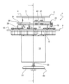
2 is a schematic front view of a coupling according to an aspect of the present invention,
3 is a schematic axial cross-sectional view of the coupling of FIG. 2,
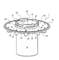
4 is a schematic perspective view of an arm portion of the coupling of FIG. 2 with an outer ring separated;
5 is a schematic perspective view of an arm portion of the coupling of FIG. 2 equipped with an outer ring;
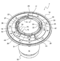
6 is a schematic plan view of the coupling of FIG. 2,
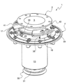
Figure 7 is a schematic perspective view of the coupling of Figure 7;
The accompanying drawings are not only used to supplement the present invention, but may also contribute to defining it where possible.
본 발명의 목적은 특히 헬리콥터인 항공기에 보조 탱크(additional reservoir)를 장착 및 제거할 수 있도록 하는 것이다. 이 항공기는 연료, 오일 또는 물을 저장하는 하나 또는 복수의 고정 탱크(fixed reservoir)를 구비한다. 항공기의 어떤 임무를 위해서는 이 유체 중의 하나의 탑재량을 증가시키는 것이 바람직하다. 이 요구는 특히 비행할 수 있는 항속 거리가 고정익 항공기보다 명백히 작은 회전익 항공기의 경우에 해당한다. 이에 따라 승객이 타지 않은 좌석 또는 비어있는 화물 공간이 보조 탱크에 사용될 수 있다. 이는 예를 들어 해상감시나 예를 들어 0 또는 부분 하중을 가지고 이동하는 등의 장거리 임무에 특히 유용하다. 분리 가능한 보조 탱크의 외부에서 분리가 수행될 수 있도록, 분리 가능한 보조 탱크를 신속히 장착 및 분리할 필요가 있다.It is an object of the present invention to be able to mount and remove an additional reservoir, in particular in an aircraft which is a helicopter. The aircraft has one or more fixed reservoirs to store fuel, oil or water. For certain aircraft missions, it is desirable to increase the payload of one of these fluids. This requirement is especially true for rotorcraft aircraft whose ranges can be flown are clearly smaller than those for fixed wing aircraft. This allows passengers to use unloaded seats or empty cargo spaces for auxiliary tanks. This is particularly useful for long-distance missions, for example maritime surveillance or moving with zero or partial loads for example. It is necessary to quickly mount and remove the detachable auxiliary tank so that the detachable auxiliary tank can be removed from the outside of the detachable auxiliary tank.
기계적 연결은 특히 중량과 항공기의 가속으로 생성된 힘들 등, 보조 탱크에 의해 인가된 힘들을 영구 장착 탱크로 전달한다. 특히 지상에 대한 충격(percussion)을 가지고 항공기가 낙하하는 경우, 보조 탱크의 기계적 연결은 상당한 힘들을 받게 된다. 극심한 응력들 하에서도 유체적 연결은 그대로 유지되는 것이 바람직하다.The mechanical connection transmits the forces applied by the auxiliary tank to the permanently mounted tank, especially the weight and forces created by the acceleration of the aircraft. Particularly when the aircraft falls with a percussion on the ground, the mechanical connection of the auxiliary tank is subjected to considerable strength. It is desirable to maintain the fluid connection even under extreme stresses.
도면들에서 볼 수 있듯, 커플링(1)은 고정 탱크(100) 또는 그 일측 상의 유체 도관과 타측 상의 분리 가능한 탱크(200)에 조립되도록 구성된다. 이를 위해, 커플링(1)은 고정 탱크 또는 유체 도관에 영구적으로 체결되는 부분과 분리 가능한 탱크에 영구적으로 체결되는 부분을 구비한다. 여기서 영구적 체결은 유지보수를 위해 분리될 수 있고, 특히 분리 가능한 탱크의 추가 장착 및 분리를 수반하는 임무의 준비 동안 등, 항공기의 정상적 사용 하에서 체결 상태를 유지하는 것을 의미한다. 커플링(1)의 두개의 부분들은 장착 상태에서 커플링(1)의 일단으로부터 타단으로의 유체의 통로를 생성하는데, 이 통로는 액밀(tight)이다. 커플링(1)은 대칭축을 가진다.As can be seen in the drawings, the coupling 1 is configured to be assembled to the fixed
커플링(1)의 회전체의 일반 형상을 가지는 숫부재(2)를 구비한다. 이 숫부재(2)는 원통부(cylindrical portion; 3)와 원주부(radial portion; 4)를 구비한다. 숫부재(2)의 축방향 단면은 L형을 가진다. 원주부(4)는 원통부(3)의 단부에서 외측으로 연장되는 칼라(collar)를 형성한다. 원주부(4)는 고정 또는 분리 가능한 탱크 중의 하나에 체결되도록 구성된다. 원주부(4)는 상기 탱크에 나사-너트로 체결될 구멍들을 구비할 수 있다. 원통부(3)는 고리형(annular) 내경부(bore)를 가진다. 원통부(3)는 원주부(4) 반대측 자유단(free end) 부근의 외면 상에 형성된 확장부(bulge; 5)를 가진다. 이 확장부(5)는 외측으로 돌출한다. 적어도 하나의 고리형 홈(annular groove 6)이 상기 확장부(5)에 배치된다. 확장부(5)는 각 홈(6)에 수납된 적어도 하나의 O-링을 구비한다. 이 O-링은 커플링의 다른 부분 또는 암부재의 내경부와 상호작용하도록 구성된다.A
숫부재(2)는 유체 통로를 형성한다. 숫부재(2)는 암부재에 액밀(liquid-tight) 상태로 미끄럼 장착되도록(slidably mounted) 구성된다. 확장부(5)는 일방향의 축방향 분리 방지 접촉부(anti-separation abutment)로 기능한다. 원주부(4)는 다른 방향의 진입 방지 접촉부(anti-sinking abutment)로 기능한다.The
커플링(1)은 암부재(female member; 7)를 구비한다. 암부재(7)는 원통부(13)와, 원주부(14)와, 및 유지부(retaining portion; 15)를 구비한다. 원통부(13) 및 원주부(14)의 축방향 단면은 L의 형태이다. 원주부(14)는 원통부(13)의 단부로부터 외측으로 연장되는 칼라를 형성한다. 원주부(13)는 제거 가능 또는 고정의 다른 탱크에 체결되도록 구성된다. 원주부(14)는 상기 다른 탱크에 나사-너트 체결되기 위한 구멍들을 구비할 수 있다. 원통부(13)는 고리형 내경부를 가진다. 원통부(13)는 원주부(14) 반대측의 자유단 부근에 확장부(12)를 가진다. 이 확장부(12)는 내측으로 돌출된다. 확장부(12)는 축방향 접촉부를 형성한다. 확장부(12)는 원통부(13)의 자유단을 보강한다. 도시된 실시예에서 확장부(12)는 고리형이다. 암부재(7)는 정상적 사용 동안 탱크들 중의 다른 것에 연결된다. 암부재(7)는 유체 통로를 형성한다.The coupling 1 has a
유지부(15)는 원통부(13) 반대측에서 원주부(14)로부터 돌출하는 축방향 돌출부로 형성된다. 유지부(15)는 원통부(13)의 내경부와 같은 높이의(flush with) 사각형 단면을 가지는 고리형 기하학적 외형(annular geometric envelope)을 가진다. 실제로, 원통부(13)의 내경부와 암부재(7)의 내경부는 같은 것이다.The holding
유지부(15)는 내측 링(16)과 외측 링(17)을 구비한다. 내측 및 외측 링(16, 17)들의 형태와 기능들은 서로 바뀔 수 있다.The holding
도시된 실시예에서, 외측 링(17)은 원주부(14)로부터 분리된 부품이다. 외측 링(17)은 예를 들어 나사 결합 등 분리 가능한 방식으로 원주부(14)에 체결된다. 외측 링(17)에는 도립된 T 단면을 가지는 고리형 부품인 원주 고리형 링(radial annular ring; 11)이 형성되어 있다. 외측 링(17)과 원주 고리형 링(11)은 단일한 부품이다. 원주 고리형 링(11)은 원주부(14)의 원주면과 접촉한다. 원주 고리형 링(11)은 예를 들어 나사 결합 등 분리 가능한 방식으로 원주부(14)에 체결된다. 원주 고리형 링(11)은 원주부(14)의 직경보다 더 작은 직경을 가진다. 원주부(14)는 밀봉을 위한 고리형 홈를 구비할 수 있다. 이 고리형 홈은 원주 고리형 링(11)의 측부 상에 위치한 원주부(14)의 표면으로부터 원주 고리형 링(11)과 원주부(14)의 자유변(free edge) 사이까지 배치될 수 있다.In the illustrated embodiment, the
내측 링(16)은 암부재(7)의 내경부로 형성되는 내면과, 외면(18)과, 및 전면(19)을 가진다. 전면(19)은 축에 직교한다. 전면(19)과 내면 사이에 모떼기(chamfer)가 위치할 수 있다. 도시된 실시예에서 넷인, 복수의 노치(notch; 20)들이 전면(19)에 배치된다. 노치(20)들은 적어도 하나가 다른 것들과 다르거나 분포가 불균일한 부채꼴 섹터(angular sector)들을 점유한다. 노치(20)들은 내측 링(16)의 축과, 또한 커플링(1)의 축을 대략 통과하는 표면들에 의해 구획된다(delimited).The
노치(20)들은 두개의 내측 및 외측 부분들로 배열된다. 내측 부분(21)은 예를 들어 20 내지 30% 등, 내측 링(16) 높이의 작은(small) 비율로 배치된다. 외측 부분(22)은 예를 들어 80 내지 90% 등 내측 링(16) 높이의 큰(major) 비율로 배치된다. 내측 부분(21)은 외측 부분(22)의 반경방향 크기(radial dimension)보다 더 작은 반경방향 크기를 가진다. 달리 말해, 내측 링(16)은 노치(20)에 대응하는(in line with) 축방향 단면으로 계단형(staircase) 단면을 가진다. 내측 링(16)은 완전한(full) 두께의 영역인 원주부(14)에서 시작하여 평면형(planar) 반경방향 계단(radial step; 23)에 의해 완전한 두께의 영역과 분리되는 감소된 두께의 영역이 위치한다. 감소된 두께의 영역은 암부재(7)의 내경부로 형성되는 내면과 만나는(join) 상면에 의해 종단된다.The
외면(18)으로부터 홈(groove; 24)들이 배치된다. 각 홈(24)은 노치(20)들 중의 하나와 만난다. 홈(24)들은 모두 좌측이건 우측이건 노치(20)들의 동일한 측부 상에 위치한다. 축방향 단면으로서의 홈(24)들의 단면은 사각형이다. 홈(24)의 내면(25)은 계단(23)과 동일면으로 그 연장이다. 홈(24)의 상면(26)은 내면(25)에 대략 평행이다. 홈(24)의 상면(26)은 해당 노치(20) 부근에서 하방을 향하는 돌출부(protrusion; 27)를 가진다. 원주 방향으로(angularly), 각 홈(24)은 일단에서 노치(20)들 중의 하나로 개방되고 노치(20)들 중의 다른 것 부근의 반대측 단에서 폐쇄된다. 홈(24)의 바닥은 고리형이고, 노치(20)들의 감소된 두께의 영역의 변(edge)들과 동축(coaxial)이며 동일한 반경을 가진다. 홈(24)과 노치(20)는 L 형상을 가진다.
외측 링(17)은 내측 링(16)의 외면(18)에 대향하여 배치된 내면(28)과, 외면(29) 및 전면(30)을 가진다. 전면(30)은 축에 직교한다. 외면(29)은 회전체(revolution)의 원통형이다. 내측 링(28)은 축방향으로 외측 링(17)의 높이에 걸치고 원주방향으로(angularly) 두개의 인접한 별도의 부채꼴 섹터(angular sector)들에 걸쳐 연장되는 두개의 인입홈(recess; 31, 32)들을 가진다. 인입홈(31, 32)들은 약 3 내지 10°로 분리될 수 있다. 인입홈(31, 32)들을 제외하면, 내면(28)은 회전체의 원통이다.The
복수의 슬롯(33)들이 외측 링(17)에 배치된다. 슬롯(33)들은 외측 링(17)의 자유단으로부터 원주부(14)를 향해 축방향으로 연장된다. 슬롯(33)들은 직선이다. 슬롯(33)은 커플링(1)의 축에 평행한 변들을 가진다. 슬롯(33)은 응축의 경우 응축수 또는 내측 및 외측 링(16, 17) 사이에 침투된 물의 배출을 가능하게 한다. 이와는 달리, 슬롯(33)들은 원주부(14) 부근에서 외측 링(17)을 관통하는 구멍들로 대체될 수 있다.A plurality of
내측 및 외측 링(16, 17) 사이에, 암부재(7)는 커플링(1)의 축에 직교하는 고리형 면(annular surface; 3)을 가진다. 이 고리형 면(34)은 반경방향이다. 고리형 면(34)은 원주 고리형 링(11)에 의해 형성된다. 고리형 면(34) 상에는 스프링(35)이 위치한다. 스프링(35)은 파형이다(undulated). 스프링(35)은 많은 권선(winding)들을 가진다. 스프링(35)은 내측 및 외측 링(16, 17)에 의해 유지된다.Between the inner and
숫부재(2)의 원통부(3) 둘레에는 숫부재(2)를 암부재(3) 내에 잠그는 부재(40)가 장착되어 있다. 이 잠금 부재(40)는 원통부(3)의 외경과 확장부(5)의 직경 사이에 포함되는 더 작은 내경을 가진다. 이에 따라 장착 상태에서 잠금 부재(40)는 제한된 원주방향(angular) 자유도와 축방향 자유도로 숫부재(2)를 지배한다. 잠금 부재(40)는 원통부(3) 상에 장착할 수 있도록 나사로 조립된 몇 개의 부채꼴 섹터들로 구현될 수 있다.A
잠금 부재(40)는 원주 칼라(radial collar; 41)와, 원주 칼라(41)의 내측 변, 원주 칼라(41)의 일측으로부터 연장되는 원통형 스커트(cylindrical skirt; 42)를 가진다. 잠금 부재(40)는 원통형 스커트(42)로부터 내측으로 약간 더 연장되는 원주 칼라(41)로 T형 단면을 가진다. 원주 칼라(41)는 작업자에 의한 파지를 촉진하도록 양각(relief)들을 구비한다. 원주 칼라(41)는 숫부재(2)의 확장부(5)에 접촉할 수 있다.The locking
잠금 부재(40)는 몇 개의 부채꼴 섹터(angular portion)들로 구현된다. 각 부채꼴 섹터는 원주 칼라(41)의 일부와 원통형 스커트(42)의 일부를 구비할 수 있다. 가 부채꼴 섹터는 숫부재(2)의 원통부(3) 또는 스커트에 장착하기에 충분한 횡방향 개구(lateral opening)를 가진다. 각 부채꼴 섹터들은 도 2, 3, 6 및 7을 참조할 수 있듯, 예를 들어 중첩된 부채꼴 섹터들의 나사 결합 등으로 분리 가능한 방식으로 함께 결합된다.The locking
원통형 스커트(42)는 잠금 동안 내측 링(16)과 외측 링(17) 사이에 수납되도록 구성된다. 원통형 스커트(24)는 내면(43)과, 외면(44)과, 및 단부면(terminal surface; 45)을 가진다. 내면(43)은 회전체의 원통형이다. 단부면(45)은 평면이다. 단부면(45)은 원주 칼라(41)에 평행하다. 단부면(45)은 커플링(1)의 축에 직교한다. 단부면(45)은 고리형 면(34)에 대향한다(opposite). 단부면(45)은 고리형 면(34) 반대측의 스프링(35)의 단부에서 상기 스프링(35)의 베어링을 수용한다. 스프링(35)은 단부면(45)과 고리형 면(34)을 분리, 이에 따라 잠금 부재(40)와 암부재(7)를 서로 분리시키는 경향이 있다.The
외면(44)에는 한정된 부채꼴 섹터 상에 배치된 홈(46)이 형성된다. 홈(46)은 예를 들어 커플링(1)의 축에 직교하는 평행한 변들을 가진다. 홈(46)은 얕은 깊이의 바닥을 가진다. 홈(46)에는 리프 스프링(leaf spring; 47)이 수납된다. 이 스프링(47)은 그 단부로 유지된다. 스프링(47)은 홈(46)의 반경방향 외측으로 돌출하는 보스(boss; 48)를 가진다. 이 보스(48)는 각 인입홈(31, 32)이 점유한 부채꼴 섹터보다 더 작은 부채꼴 섹터를 점유한다. 보스(48)는 외면(44)에 대해 각 인입홈(31, 32)의 깊이보다 더 작은 축방향 크기를 가진다. 이에 따라, 보스(48)는 축방향 이동 동안 인입홈(31, 32)들 중의 하나에 진입한 다음, 회전 후에는 인입홈(31, 32)들 중의 다른 것 내로 돌출한다. 도시된 실시예에서, 스프링(47)은 인입홈들과 상호작용하는 원주방향 브레이크(angular brake)를 형성한다. 이와는 달리, 스프링(47)이 그 사이에 인입홈들을 형성하는 융기부(protuberance)들과 상호작용할 수도 있다.The
잠금 부재(40)는 내면(43)으로부터 내측으로 돌출하는 복수의 이빨(teeth; 49) 형태의 록(lock)을 구비한다. 이 이빨(49)들은 단부면(45)과 동일 평면인 변을 가진다. 이빨(49)들은 원주 칼라(41)에 대향하여 위치하는 반대측 변을 가진다. 상기 반대측 변은 원주 칼라(41)에 평행한 평면 내에 위치한다. 상기 반대측 변은 잠금 상태의 스프링(35) 응력 하에서 홈(24)의 상변과 상호작용한다.The locking
이빨(49)들은 동일한 중심 및 반경의 원의 원호(arc)로서의 내면들을 가진다. 상기 내면은 원주 칼라(41)의 내경보다 큰 직경을 가진다. 상기 내면은 홈(24)들의 바닥의 직경보다 더 큰 직경을 가진다. 이빨(49)들은 커플링(1)의 축을 통과하는 평면들 내에 위치하는 단부면(end surface)들을 가진다.The
이빨(49)들은 분리된 부채꼴 섹터들을 점유한다. 이빨(49)들은 노치(20)들의 부채꼴 섹터에 대응하는 부채꼴 섹터들을 점유한다. 이에 따라, 각 이빨(49)은, 각 이빨(49)이 축방향 이동을 통해 해당 노치(20)에 진입할 수 있도록 가까운 공차 내에서 한개의 노치(20)에 대응한다.The
이빨(49)들의 노치(20)들로의 진입과 동시에, 스프링(47)의 보스(48)가 인입홈(31, 32)들 중의 하나에 진입한다. 암부재(7)에 대한 잠금 부재의 상대적 축방향 이동 동안, 스프링(35)이 압축된다. 그러면 스프링(35)에 대한 축방향 힘을 유지하면서 회전이 작용된다. 각 이빨(49)은 돌출부(27) 하부를 미끄러짐으로써 해당 노치(20)로부터 홈(24)들 중의 하나로 통과된다. 보스(48)는 외측 링(17)의 내면(28)에 의해 반경방향 내측으로 압축된다.Simultaneously with the entry of the
회전 운동의 종단에서, 각 이빨(49)은 돌출부(27)를 지나친다. 보스(48)는 초기 형태로 복원되는 경향을 가지며, 스프링(47)은 인입홈(32, 31)들 중의 다른 것을 해제한다. 스프링(35)에 대한 축방향 힘이 중단된다. 스프링(35)의 해제는 이빨(49)을 홈(24)의 상면(26)에 대해 밀게 된다. 반대 방향의 회전이 각 홈(24)의 돌출부(27)에 의해 방지된다.At the end of the rotational motion, each
이와 같이, 잠금 부재(40)는 축방향(이동)에 의해 작동되어 회전 운동할 수 있고 축방향(이동)에 의해 해제되어 회전 운동할 수 있는 축방향 차단 록(axial blocking lock)과, 회전 브레이크(rotational brake)를 구비하고, 록과 브레이크는 잠금 위치에서 작동 가능하게(active) 된다. 스프링(35 및 47)들은 이중 안전(장치)을 형성한다.In this way, the locking
커플링(1)은 암부재(7)에 장착된 차단 밸브(shut-off valve; 50)를 구비한다. 이 차단 밸브(50)는 암부재(7)에 대해 미끄럼 가능하게(slidably) 장착되는데, 이 미끄럼(이동)은 커플링(1)의 축을 따른다. 차단 밸브(50)는 확장부(12) 부근에 배치된 시트(seat; 52)와 밀착되도록 구성된 원형 셔터(circular shutter; 51)를 구비한다. 시트(52)는 확장부(12)의 내경부(bore)와 암부재(7)의 원통부(13)의 자유단 사이에 형성된 모떼기(chamfer)의 형태를 가질 수 있다. 차단 밸브(50)는 원형 셔터(51)와 일체인 제어 및 유지 로드(control and retaining rod; 53)를 구비한다. 이 제어 및 유지 로드(53)는 원통부(13)의 내경부 내로 돌출한다. 제어 및 유지 로드(53)는 원형 셔터(51)에 체결된 단부와 칼라(58) 형태의 단부를 가진다. 차단 밸브(50)는 암부재(7)의 원통부(13)의 내경부가 폐쇄되는 폐쇄 위치(closed-off position)와 개방 위치를 가진다.The coupling 1 has a shut-off
암부재(7)는 차단 밸브(50)에 대한 지지부(54)를 구비한다. 이 지지부(54)는 적어도 하나, 예를 들어 세 아암(arm; 55)들과 중앙의 관형 슬리이브(tubular sleeve; 56)를 포함한다. 이 관형 슬리이브(56)는 암부재(7)의 원통부(13)와 동축이다. 아암(55)들은 축방향으로 유체 통로를 자유로이 남기고 관형 슬리이브(56)와 확장부(12) 사이에 반경방향으로 연장된다. 제어 및 유지 로드(53)는 관형 슬리이브(56)의 내경부 내에서 이동하기에 적합한 직경이다. 스프링(57)이 제어 및 유지 로드(53) 둘레와 관형 슬리이브(56) 둘레에 장착된다. 스프링(57)은 차단 밸브(50)를 폐쇄하는 경향을 가진다. 여기서 스프링(57)은 일측이 아암(55)(들) 또는 아암(55)(들)과 관형 슬리이브(55) 사이에 위치한 칼라 상에 지지되고 타측이 칼라(58) 상에 지지된다. 스프링(57)은 폐쇄 위치 및 개방 위치에서 제어 및 유지 로드(53) 상에 영구적인 힘을 인가한다. 지지부(54)는 원통부(13)와 단일 부품이다.The
숫부재(2)는 차단 밸브(50) 상에 작용하는 태핏(tappet; 60)을 구비한다. 이 태핏(60)은 지지부(54)의 구조와 유사한 구조를 가진다. 태핏(60)은 적어도 하나, 예를 들어 세 아암(61)들과 여기서는 중앙 핀(63)으로 형성되는 접촉면(abutment surface; 62)을 포함한다. 접촉면(62)은 커플링(1)의 축에 직교한다. 아암(61)(들)은 핀(63)과 원통부(3)의 내경부 사이에 반경방향으로 연장된다. 태핏(60)은 원통부(3)와 단일 부품이다.The
아암(61)(들)은 축방향으로 유체 통로를 자유로이 남긴다. 태핏(60)의 접촉면(62)은 연결된 고정 및 분리 가능한 탱크들에 해당하는 도 2, 3 및 7에 도시된 위치에서 차단 밸브(50)가 스프링(57) 반대측이 칼라(58)의 접촉면(62) 상의 지지로 개방되도록 하는 방식으로 축방향에 위치한다. 그러면 원형 셔터(51)가 시트(52)로부터 분리된다.The arm 61(s) freely leaves a fluid passageway in the axial direction. The
분리 가능한 탱크의 분리 동안, 숫부재(2)는 원주부(4)와 원주부(14)를 분리시키는 축방향 이동을 통해 후퇴한다. 차단 밸브(50)는 차단 밸브(50)가 시트(52)에 의해 정지될 때까지 상기 축방향 이동에 동반한다. 그러면 접촉면(62)이 칼라(58)로부터 분리된다. 차단 밸브(50)는 숫부재(2)가 암부재(7) 외부로 이탈하기 전에, 더 정확히는 O-링이 홈(6)으로부터 원통부(13)의 내경부 외부로 이탈하기 전에 폐쇄된다. 적절한 차단(blocking off)을 제공하도록 스프링(57)은 사전응력이 부여된(prestressed) 상태를 유지한다.During the separation of the detachable tank, the
반대 방향으로, 숫부재(2)가 암부재(7) 내로 삽입된다. 홈(6)의 O-링은 원통부(13)의 내경부로 진입하여 밀봉을 제공한다. 그러면 태핏(60)이 차단 밸브(50)에 접촉된다. 더 정확히는, 접촉면(62)이 칼라(58)를 밀어 차단 밸브(50)가 숫부재(2)와 함께 이동하고 스프링(57)을 압축하며 유체 통로를 개방하도록 한다. 도 2, 3 및 7에 도시된 이 축방향 위치에서, 잠금 부재(40)는 회전에 의해 잠금 위치로 거동하야 고정 및 분리 가능한 탱크들 간에 안정된 연결을 제공한다.In the opposite direction, the
이와 같이 커플링(1)은 숫 및 암부재들의 상대 위치에 기계적으로 연동되는 거동을 가지는 차단 밸브(50)를 구비한다. 차단 밸브는 분리되면 탱크들 중의 하나를 자동으로 폐쇄한다. 작업자가 폐쇄를 위해 추가적인 단계를 수행할 필요가 없다.In this way, the coupling 1 includes a shut-off
본 발명은 단지 일예인 이상에 설명된 방법 및 장치의 예들에 한정되지 않으며, 이하의 청구항들의 범위 내에서 당업계에 통상의 기술을 가진 자가 고려할 수 있는 모든 대안들을 포괄한다.The present invention is not limited to the examples of the method and apparatus described above, which is merely an example, and encompasses all alternatives contemplated by those of ordinary skill in the art within the scope of the following claims.
Claims (10)
제1 탱크에 연결되도록 구성되고, 통로를 형성하며 원통부(13)와 원주부(14)를 포함하는 암부재(7)와,
제2 탱크에 연결되도록 구성되고, 통로를 형성하며 상기 암부재(7)에 액밀 상태로 미끄럼 가능하게 결합되고, 원통부(3)와 원주부(4)를 포함하는 숫부재(2)와, 그리고
숫부재(2)를 암부재(7) 내에 체결하는 잠금 부재(40)로, 암부재(7)의 원주부(14)와 숫부재(2)의 원주부(4) 사이에 배치되며, 암부재(7)에 대한 숫부재의 제한된 미끄럼 범위를 제공하고 숫부재(2)를 둘러싸며, 잠금 위치에서 암부재(7)와 맞물리고 해제 위치에서 암부재(7)를 풀어주고, 축방향 이동에 의해 작동되어 회전 운동하고 축방향 이동에 의해 해제되어 회전 운동할 수 있는 축방향 차단 록 및 회전 브레이크를 포함하여, 록과 브레이크가 잠금 위치에서 작동 가능하게 되는 상기 잠금 부재(40)를 포함하여 구성되는 신속 커플링 장치.It is a quick coupling (1) device that transfers liquid to an aircraft,
An arm member 7 configured to be connected to the first tank, forming a passage, and including a cylindrical portion 13 and a circumferential portion 14,
A male member (2) configured to be connected to a second tank, forming a passage and slidably coupled to the arm member (7) in a liquid-tight state, and comprising a cylindrical portion (3) and a circumferential portion (4), And
A locking member 40 for fastening the male member 2 into the female member 7, and is disposed between the circumferential portion 14 of the female member 7 and the circumferential portion 4 of the male member 2, and Provides a limited sliding range of the male member relative to the member (7), surrounds the male member (2), engages the female member (7) in the locked position and releases the arm member (7) in the released position, and moves axially Including an axial blocking lock and a rotation brake that is actuated to rotate and is released by an axial movement to perform rotational movement, and the locking member 40 in which the lock and the brake are operable in the locked position. Consisting of a quick coupling device.
암부재(7)는 암부재(7)의 원주부(14)와 일체인 두개의 동심 링들을 구비하고, 제1 링(16)은 록과 상호작용하도록 구성된 복수의 L형 홈들을 포함하며, 제2 링(17)은 상기 제2 링(17)의 높이에 걸쳐 축방향으로 연장되어 브레이크와 맞물리도록 구성된 제1 오목부(31) 및 제1 오목부(31)에 대해 원주방향으로 편심되고 잠금 위치에서 브레이크와 상호작용하도록 구성된 제2 오목부(32)를 포함하는 신속 커플링 장치.The method of claim 1,
The arm member 7 has two concentric rings integral with the circumferential portion 14 of the arm member 7 and the first ring 16 includes a plurality of L-shaped grooves configured to interact with the lock, The second ring 17 is eccentric in the circumferential direction with respect to the first concave portion 31 and the first concave portion 31 configured to extend axially over the height of the second ring 17 to engage the brake A quick coupling device comprising a second recess (32) configured to interact with the brake in a locked position.
각각의 L형 홈은 제1 링(16)의 두께의 일부 상에 배치된 축부(20)와, 제1 링의 제한된 원주방향 섹터 상에 배치된 원주방향부(24), 및 축부의 부근에서 암부재(7)의 원주부(14)를 향하여 록의 잠금 위치를 구획하는 돌출부(27)를 구비하는 신속 커플링 장치.The method of claim 2,
Each L-shaped groove has a shaft portion 20 disposed on a portion of the thickness of the first ring 16, a circumferential portion 24 disposed on a limited circumferential sector of the first ring, and in the vicinity of the shaft portion. A quick coupling device having a protrusion (27) for partitioning the locking position of the lock toward the circumferential portion (14) of the arm member (7).
L형 홈들이 원주방향으로 불규칙하게 배치되는 신속 커플링 장치.The method according to claim 2 or 3,
Quick coupling device in which L-shaped grooves are irregularly arranged in the circumferential direction.
링들 중의 하나는 외측링이고, 암부재(7)의 원주부(14) 부근에 반경방향 개구(33)들을 구비하는 신속 커플링 장치.The method according to any one of claims 2 to 4,
One of the rings is an outer ring and a quick coupling device having radial openings 33 near the circumferential portion 14 of the arm member 7.
일반적인 고리형의 축방향 작용 스프링(35)이 상기 동축 링(16, 17)들 사이에 위치하여 잠금 위치에서 잠금 부재(40)에 축방향 사전응력을 인가하는 신속 커플링 장치.The method according to any one of claims 2 to 5,
A quick coupling device in which a general annular axial action spring (35) is positioned between the coaxial rings (16, 17) to apply an axial prestress to the locking member (40) in the locked position.
상기 스프링(35)은 파형이고 몇 개의 권선들을 구비하는 신속 커플링 장치.The method of claim 6,
The spring (35) is corrugated and has several windings.
잠금 부재(40)는 축방향 차단 록을 지지하는 축방향 스커트(42)를 구비하고, 축방향 차단 록은 암부재(7)를 향하는 복수의 이빨(49)을 구비하며, 이빨(49)은 동축이고, 각각의 이빨(49)이 부채꼴 섹터를 형성하며 평행한 평면들의 일부인 모서리들을 가지는 신속 커플링 장치.The method according to any one of claims 1 to 7,
The locking member 40 is provided with an axial skirt 42 for supporting the axial blocking lock, the axial blocking lock has a plurality of teeth 49 facing the arm member 7, and the teeth 49 are A quick coupling device that is coaxial and has corners where each tooth 49 forms a sectoral sector and is part of parallel planes.
잠금 부재(40)가 적어도 두개의 부분들로 구성되는 신속 커플링 장치.The method according to any one of claims 1 to 8,
A quick coupling device in which the locking member 40 consists of at least two parts.
브레이크가 고리형 또는 원의 원호이고, 반경방향 외측을 향하며 암부재(7), 특히 암부재(7)에 배치된 오목부와 상호작용하도록 구성된 보스(48)를 가지는 스프링(47)을 구비하는 신속 커플링 장치.The method according to any one of claims 1 to 9,
The brake is of an annular or circular arc, facing radially outward and having a spring 47 having a boss 48 configured to interact with an arm member 7, in particular a recess disposed in the arm member 7 Quick coupling device.
Applications Claiming Priority (2)
| Application Number | Priority Date | Filing Date | Title |
|---|---|---|---|
| FRFR1901463 | 2019-02-13 | ||
| FR1901463A FR3092641B1 (en) | 2019-02-13 | 2019-02-13 | FUEL TRANSFER QUICK COUPLING |
Publications (2)
| Publication Number | Publication Date |
|---|---|
| KR20200099103A true KR20200099103A (en) | 2020-08-21 |
| KR102787502B1 KR102787502B1 (en) | 2025-03-31 |
Family
ID=67185295
Family Applications (1)
| Application Number | Title | Priority Date | Filing Date |
|---|---|---|---|
| KR1020200017202A Active KR102787502B1 (en) | 2019-02-13 | 2020-02-12 | Quick coupling for fuel transfer |
Country Status (6)
| Country | Link |
|---|---|
| US (1) | US11333271B2 (en) |
| EP (1) | EP3696091B1 (en) |
| KR (1) | KR102787502B1 (en) |
| CN (1) | CN111561624B (en) |
| CA (1) | CA3072238A1 (en) |
| FR (1) | FR3092641B1 (en) |
Citations (2)
| Publication number | Priority date | Publication date | Assignee | Title |
|---|---|---|---|---|
| US20030107218A1 (en) * | 2001-12-12 | 2003-06-12 | Pilot Industries, Inc. | Spud assembly for a fuel tank |
| US20150107682A1 (en) * | 2013-09-27 | 2015-04-23 | Long Range Ag | Methods, systems and apparatus for aircraft auxiliary fuel tanks |
Family Cites Families (9)
| Publication number | Priority date | Publication date | Assignee | Title |
|---|---|---|---|---|
| FR1526167A (en) * | 1967-04-10 | 1968-05-24 | Fenwick | Quick-fit fitting of the so-called bayonet type for pressurized fluid piping |
| US3596936A (en) * | 1969-11-06 | 1971-08-03 | Dunham Bush Inc | Quick connect air duct fittings |
| FR2943627B1 (en) * | 2009-03-31 | 2012-11-16 | Snecma | DEVICE FOR SEPARATING BOTH PARTS OF A LAUNCHER FEEDING MODULE |
| FR2955572B1 (en) * | 2010-01-28 | 2014-05-02 | Eurocopter France | DEVICE FOR FILLING A TANK BY GRAVITY OR PRESSURE |
| FR3012441A1 (en) * | 2013-10-29 | 2015-05-01 | Peugeot Citroen Automobiles Sa | FLUID CONNECTION FOR PERMITTING THE FILLING OF AN AUXILIARY TANK FOR A MOTOR VEHICLE |
| FR3016950B1 (en) * | 2014-01-28 | 2016-08-26 | Boutte | CONNECTOR FOR FLUID TRANSPORT CIRCUIT AND FLUID TRANSPORT CIRCUIT COMPRISING SUCH A CONNECTION |
| US10683954B2 (en) * | 2014-04-15 | 2020-06-16 | Eaton Intelligent Power Limited | Bulkhead connector assembly |
| DE102014214705A1 (en) * | 2014-07-25 | 2016-01-28 | Ti Automotive Technology Center Gmbh | Implementation device for a wall |
| GB2548559A (en) * | 2016-03-17 | 2017-09-27 | Eaton Ltd | Aircraft fluid line coupling assembly for releasably interconnecting fluid conveying members |
-
2019
- 2019-02-13 FR FR1901463A patent/FR3092641B1/en not_active Expired - Fee Related
-
2020
- 2020-02-11 CA CA3072238A patent/CA3072238A1/en active Pending
- 2020-02-11 EP EP20156571.0A patent/EP3696091B1/en active Active
- 2020-02-12 CN CN202010088354.1A patent/CN111561624B/en active Active
- 2020-02-12 US US16/788,960 patent/US11333271B2/en active Active
- 2020-02-12 KR KR1020200017202A patent/KR102787502B1/en active Active
Patent Citations (2)
| Publication number | Priority date | Publication date | Assignee | Title |
|---|---|---|---|---|
| US20030107218A1 (en) * | 2001-12-12 | 2003-06-12 | Pilot Industries, Inc. | Spud assembly for a fuel tank |
| US20150107682A1 (en) * | 2013-09-27 | 2015-04-23 | Long Range Ag | Methods, systems and apparatus for aircraft auxiliary fuel tanks |
Also Published As
| Publication number | Publication date |
|---|---|
| US11333271B2 (en) | 2022-05-17 |
| FR3092641B1 (en) | 2021-11-19 |
| EP3696091B1 (en) | 2021-03-10 |
| FR3092641A1 (en) | 2020-08-14 |
| CA3072238A1 (en) | 2020-08-13 |
| EP3696091A1 (en) | 2020-08-19 |
| US20200256492A1 (en) | 2020-08-13 |
| KR102787502B1 (en) | 2025-03-31 |
| CN111561624B (en) | 2023-06-06 |
| CN111561624A (en) | 2020-08-21 |
Similar Documents
| Publication | Publication Date | Title |
|---|---|---|
| US4905733A (en) | Breakaway hose coupling | |
| US20170050194A1 (en) | Centrifuge rotor | |
| US4280679A (en) | Dually-operated tank car bottom unloading valve | |
| US11255398B2 (en) | Multi-actor damping systems and methods | |
| US11498662B2 (en) | Electrically operated landing gear lock system | |
| EP4107064B1 (en) | Clutch assembly for autonomous taxiing of aircraft | |
| US5361801A (en) | Ball valve | |
| CN103481885A (en) | Pneumatic brake actuator chamber with rotationally positionable housing | |
| KR102787502B1 (en) | Quick coupling for fuel transfer | |
| US4465202A (en) | Fluid container with venting means | |
| US3086565A (en) | Servicing nozzle | |
| EP3159179A2 (en) | Mismatch side rim and lock ring interface angles for lock ring wheel | |
| US4782974A (en) | Oil tank safety cap adapter and method of application by retrofitting | |
| US12091164B2 (en) | Multi-actor damping systems and methods | |
| US2573207A (en) | Liquid discharge mechanism | |
| US5056678A (en) | Access port sealing device | |
| RU2805671C1 (en) | Quick connection for pumping fuel | |
| CN102159866B (en) | Aviation fueling hydrant coupler with internal actuating collar lock | |
| JP2017210228A (en) | Retraction/extension of landing gear in aircraft | |
| US10094514B1 (en) | Self-closing drain plugs with redundant sealing | |
| US4739612A (en) | Shuttle valve for oil tank filler neck | |
| US12454979B2 (en) | Self-lubricating pin | |
| EP3805097B1 (en) | Electrically operated landing gear lock system | |
| CN113167428B (en) | pressure seal plug | |
| US12617524B2 (en) | Uplock unlock electro-hydrostatic actuator |
Legal Events
| Date | Code | Title | Description |
|---|---|---|---|
| PA0109 | Patent application |
Patent event code: PA01091R01D Comment text: Patent Application Patent event date: 20200212 |
|
| PG1501 | Laying open of application | ||
| A201 | Request for examination | ||
| PA0201 | Request for examination |
Patent event code: PA02012R01D Patent event date: 20230125 Comment text: Request for Examination of Application Patent event code: PA02011R01I Patent event date: 20200212 Comment text: Patent Application |
|
| PE0902 | Notice of grounds for rejection |
Comment text: Notification of reason for refusal Patent event date: 20240625 Patent event code: PE09021S01D |
|
| E701 | Decision to grant or registration of patent right | ||
| PE0701 | Decision of registration |
Patent event code: PE07011S01D Comment text: Decision to Grant Registration Patent event date: 20250123 |
|
| GRNT | Written decision to grant | ||
| PR0701 | Registration of establishment |
Comment text: Registration of Establishment Patent event date: 20250324 Patent event code: PR07011E01D |
|
| PR1002 | Payment of registration fee |
Payment date: 20250325 End annual number: 3 Start annual number: 1 |
|
| PG1601 | Publication of registration |