KR20210077009A - Latch activation between elements - Google Patents
Latch activation between elements Download PDFInfo
- Publication number
- KR20210077009A KR20210077009A KR1020217018617A KR20217018617A KR20210077009A KR 20210077009 A KR20210077009 A KR 20210077009A KR 1020217018617 A KR1020217018617 A KR 1020217018617A KR 20217018617 A KR20217018617 A KR 20217018617A KR 20210077009 A KR20210077009 A KR 20210077009A
- Authority
- KR
- South Korea
- Prior art keywords
- spool
- detent
- self
- lifeline
- contracting
- Prior art date
- Legal status (The legal status is an assumption and is not a legal conclusion. Google has not performed a legal analysis and makes no representation as to the accuracy of the status listed.)
- Granted
Links
Images








Classifications
-
- F—MECHANICAL ENGINEERING; LIGHTING; HEATING; WEAPONS; BLASTING
- F16—ENGINEERING ELEMENTS AND UNITS; GENERAL MEASURES FOR PRODUCING AND MAINTAINING EFFECTIVE FUNCTIONING OF MACHINES OR INSTALLATIONS; THERMAL INSULATION IN GENERAL
- F16D—COUPLINGS FOR TRANSMITTING ROTATION; CLUTCHES; BRAKES
- F16D59/00—Self-acting brakes, e.g. coming into operation at a predetermined speed
-
- A—HUMAN NECESSITIES
- A62—LIFE-SAVING; FIRE-FIGHTING
- A62B—DEVICES, APPARATUS OR METHODS FOR LIFE-SAVING
- A62B1/00—Devices for lowering persons from buildings or the like
- A62B1/06—Devices for lowering persons from buildings or the like by making use of rope-lowering devices
-
- A—HUMAN NECESSITIES
- A62—LIFE-SAVING; FIRE-FIGHTING
- A62B—DEVICES, APPARATUS OR METHODS FOR LIFE-SAVING
- A62B1/00—Devices for lowering persons from buildings or the like
- A62B1/06—Devices for lowering persons from buildings or the like by making use of rope-lowering devices
- A62B1/08—Devices for lowering persons from buildings or the like by making use of rope-lowering devices with brake mechanisms for the winches or pulleys
-
- A—HUMAN NECESSITIES
- A62—LIFE-SAVING; FIRE-FIGHTING
- A62B—DEVICES, APPARATUS OR METHODS FOR LIFE-SAVING
- A62B35/00—Safety belts or body harnesses; Similar equipment for limiting displacement of the human body, especially in case of sudden changes of motion
- A62B35/0093—Fall arrest reel devices
-
- F—MECHANICAL ENGINEERING; LIGHTING; HEATING; WEAPONS; BLASTING
- F16—ENGINEERING ELEMENTS AND UNITS; GENERAL MEASURES FOR PRODUCING AND MAINTAINING EFFECTIVE FUNCTIONING OF MACHINES OR INSTALLATIONS; THERMAL INSULATION IN GENERAL
- F16D—COUPLINGS FOR TRANSMITTING ROTATION; CLUTCHES; BRAKES
- F16D43/00—Automatic clutches
- F16D43/02—Automatic clutches actuated entirely mechanically
- F16D43/04—Automatic clutches actuated entirely mechanically controlled by angular speed
- F16D43/14—Automatic clutches actuated entirely mechanically controlled by angular speed with centrifugal masses actuating the clutching members directly in a direction which has at least a radial component; with centrifugal masses themselves being the clutching members
-
- F—MECHANICAL ENGINEERING; LIGHTING; HEATING; WEAPONS; BLASTING
- F16—ENGINEERING ELEMENTS AND UNITS; GENERAL MEASURES FOR PRODUCING AND MAINTAINING EFFECTIVE FUNCTIONING OF MACHINES OR INSTALLATIONS; THERMAL INSULATION IN GENERAL
- F16D—COUPLINGS FOR TRANSMITTING ROTATION; CLUTCHES; BRAKES
- F16D63/00—Brakes not otherwise provided for; Brakes combining more than one of the types of groups F16D49/00 - F16D61/00
- F16D63/002—Brakes with direct electrical or electro-magnetic actuation
-
- F—MECHANICAL ENGINEERING; LIGHTING; HEATING; WEAPONS; BLASTING
- F16—ENGINEERING ELEMENTS AND UNITS; GENERAL MEASURES FOR PRODUCING AND MAINTAINING EFFECTIVE FUNCTIONING OF MACHINES OR INSTALLATIONS; THERMAL INSULATION IN GENERAL
- F16D—COUPLINGS FOR TRANSMITTING ROTATION; CLUTCHES; BRAKES
- F16D63/00—Brakes not otherwise provided for; Brakes combining more than one of the types of groups F16D49/00 - F16D61/00
- F16D63/006—Positive locking brakes
-
- H—ELECTRICITY
- H02—GENERATION; CONVERSION OR DISTRIBUTION OF ELECTRIC POWER
- H02K—DYNAMO-ELECTRIC MACHINES
- H02K49/00—Dynamo-electric clutches; Dynamo-electric brakes
- H02K49/02—Dynamo-electric clutches; Dynamo-electric brakes of the asynchronous induction type
- H02K49/04—Dynamo-electric clutches; Dynamo-electric brakes of the asynchronous induction type of the eddy-current hysteresis type
-
- H—ELECTRICITY
- H02—GENERATION; CONVERSION OR DISTRIBUTION OF ELECTRIC POWER
- H02K—DYNAMO-ELECTRIC MACHINES
- H02K49/00—Dynamo-electric clutches; Dynamo-electric brakes
- H02K49/10—Dynamo-electric clutches; Dynamo-electric brakes of the permanent-magnet type
- H02K49/104—Magnetic couplings consisting of only two coaxial rotary elements, i.e. the driving element and the driven element
-
- H—ELECTRICITY
- H02—GENERATION; CONVERSION OR DISTRIBUTION OF ELECTRIC POWER
- H02K—DYNAMO-ELECTRIC MACHINES
- H02K49/00—Dynamo-electric clutches; Dynamo-electric brakes
- H02K49/10—Dynamo-electric clutches; Dynamo-electric brakes of the permanent-magnet type
- H02K49/104—Magnetic couplings consisting of only two coaxial rotary elements, i.e. the driving element and the driven element
- H02K49/106—Magnetic couplings consisting of only two coaxial rotary elements, i.e. the driving element and the driven element with a radial air gap
-
- F—MECHANICAL ENGINEERING; LIGHTING; HEATING; WEAPONS; BLASTING
- F16—ENGINEERING ELEMENTS AND UNITS; GENERAL MEASURES FOR PRODUCING AND MAINTAINING EFFECTIVE FUNCTIONING OF MACHINES OR INSTALLATIONS; THERMAL INSULATION IN GENERAL
- F16D—COUPLINGS FOR TRANSMITTING ROTATION; CLUTCHES; BRAKES
- F16D23/00—Details of mechanically-actuated clutches not specific for one distinct type
- F16D23/12—Mechanical clutch-actuating mechanisms arranged outside the clutch as such
- F16D2023/123—Clutch actuation by cams, ramps or ball-screw mechanisms
-
- F—MECHANICAL ENGINEERING; LIGHTING; HEATING; WEAPONS; BLASTING
- F16—ENGINEERING ELEMENTS AND UNITS; GENERAL MEASURES FOR PRODUCING AND MAINTAINING EFFECTIVE FUNCTIONING OF MACHINES OR INSTALLATIONS; THERMAL INSULATION IN GENERAL
- F16D—COUPLINGS FOR TRANSMITTING ROTATION; CLUTCHES; BRAKES
- F16D43/00—Automatic clutches
- F16D43/02—Automatic clutches actuated entirely mechanically
- F16D43/04—Automatic clutches actuated entirely mechanically controlled by angular speed
- F16D43/14—Automatic clutches actuated entirely mechanically controlled by angular speed with centrifugal masses actuating the clutching members directly in a direction which has at least a radial component; with centrifugal masses themselves being the clutching members
- F16D2043/145—Automatic clutches actuated entirely mechanically controlled by angular speed with centrifugal masses actuating the clutching members directly in a direction which has at least a radial component; with centrifugal masses themselves being the clutching members the centrifugal masses being pivoting
-
- F—MECHANICAL ENGINEERING; LIGHTING; HEATING; WEAPONS; BLASTING
- F16—ENGINEERING ELEMENTS AND UNITS; GENERAL MEASURES FOR PRODUCING AND MAINTAINING EFFECTIVE FUNCTIONING OF MACHINES OR INSTALLATIONS; THERMAL INSULATION IN GENERAL
- F16D—COUPLINGS FOR TRANSMITTING ROTATION; CLUTCHES; BRAKES
- F16D2125/00—Components of actuators
- F16D2125/18—Mechanical mechanisms
- F16D2125/20—Mechanical mechanisms converting rotation to linear movement or vice versa
- F16D2125/34—Mechanical mechanisms converting rotation to linear movement or vice versa acting in the direction of the axis of rotation
- F16D2125/36—Helical cams, Ball-rotating ramps
-
- F—MECHANICAL ENGINEERING; LIGHTING; HEATING; WEAPONS; BLASTING
- F16—ENGINEERING ELEMENTS AND UNITS; GENERAL MEASURES FOR PRODUCING AND MAINTAINING EFFECTIVE FUNCTIONING OF MACHINES OR INSTALLATIONS; THERMAL INSULATION IN GENERAL
- F16D—COUPLINGS FOR TRANSMITTING ROTATION; CLUTCHES; BRAKES
- F16D2127/00—Auxiliary mechanisms
- F16D2127/001—Auxiliary mechanisms for automatic or self-acting brake operation
- F16D2127/002—Auxiliary mechanisms for automatic or self-acting brake operation speed-responsive
-
- F—MECHANICAL ENGINEERING; LIGHTING; HEATING; WEAPONS; BLASTING
- F16—ENGINEERING ELEMENTS AND UNITS; GENERAL MEASURES FOR PRODUCING AND MAINTAINING EFFECTIVE FUNCTIONING OF MACHINES OR INSTALLATIONS; THERMAL INSULATION IN GENERAL
- F16D—COUPLINGS FOR TRANSMITTING ROTATION; CLUTCHES; BRAKES
- F16D2129/00—Type of operation source for auxiliary mechanisms
- F16D2129/06—Electric or magnetic
- F16D2129/065—Permanent magnets
-
- Y—GENERAL TAGGING OF NEW TECHNOLOGICAL DEVELOPMENTS; GENERAL TAGGING OF CROSS-SECTIONAL TECHNOLOGIES SPANNING OVER SEVERAL SECTIONS OF THE IPC; TECHNICAL SUBJECTS COVERED BY FORMER USPC CROSS-REFERENCE ART COLLECTIONS [XRACs] AND DIGESTS
- Y02—TECHNOLOGIES OR APPLICATIONS FOR MITIGATION OR ADAPTATION AGAINST CLIMATE CHANGE
- Y02B—CLIMATE CHANGE MITIGATION TECHNOLOGIES RELATED TO BUILDINGS, e.g. HOUSING, HOUSE APPLIANCES OR RELATED END-USER APPLICATIONS
- Y02B10/00—Integration of renewable energy sources in buildings
- Y02B10/30—Wind power
-
- Y—GENERAL TAGGING OF NEW TECHNOLOGICAL DEVELOPMENTS; GENERAL TAGGING OF CROSS-SECTIONAL TECHNOLOGIES SPANNING OVER SEVERAL SECTIONS OF THE IPC; TECHNICAL SUBJECTS COVERED BY FORMER USPC CROSS-REFERENCE ART COLLECTIONS [XRACs] AND DIGESTS
- Y02—TECHNOLOGIES OR APPLICATIONS FOR MITIGATION OR ADAPTATION AGAINST CLIMATE CHANGE
- Y02E—REDUCTION OF GREENHOUSE GAS [GHG] EMISSIONS, RELATED TO ENERGY GENERATION, TRANSMISSION OR DISTRIBUTION
- Y02E10/00—Energy generation through renewable energy sources
- Y02E10/70—Wind energy
- Y02E10/72—Wind turbines with rotation axis in wind direction
Landscapes
- Engineering & Computer Science (AREA)
- General Engineering & Computer Science (AREA)
- Mechanical Engineering (AREA)
- Health & Medical Sciences (AREA)
- General Health & Medical Sciences (AREA)
- Business, Economics & Management (AREA)
- Emergency Management (AREA)
- Power Engineering (AREA)
- Dynamo-Electric Clutches, Dynamo-Electric Brakes (AREA)
- Transmission Devices (AREA)
- X-Ray Techniques (AREA)
- Magnetic Bearings And Hydrostatic Bearings (AREA)
- One-Way And Automatic Clutches, And Combinations Of Different Clutches (AREA)
- Emergency Lowering Means (AREA)
- Automotive Seat Belt Assembly (AREA)
- Braking Arrangements (AREA)
- Electromagnets (AREA)
Abstract
본 발명은 부재들 사이의 상대적 움직임의 멈춤을 야기하는 부재들 사이의 동적인 응답을 지배하는 시스템을 사용하는 자가 수축 생명줄(SRL) 장치와, 시스템, 및 사용 방법에 관한 것이다. 자기 상호 작용, 와전류 드래그 힘, 원심력 및/또는 관성력이, 지배하는 움직임의 다양한 메커니즘들을 제공할 수 있다.The present invention relates to a self-contracting lifeline (SRL) device, system, and method of use that uses a system that governs a dynamic response between members causing a stop in relative motion between the members. Magnetic interactions, eddy current drag forces, centrifugal forces, and/or inertial forces may provide various mechanisms of dominating motion.
Description
본 발명은 부재들 사이의 상대 속도를 제어하기 위한 시스템, 사용 방법, 및 그러한 시스템을 사용하는 자가 수축 생명줄(SRL:Self Retracting Lifeline)에 관한 것이다.The present invention relates to a system, method of use, and a Self Retracting Lifeline (SRL) using such a system for controlling the relative velocity between members.
와전류 관련 장치들 분야에서의 본 출원인의 공동 계류중이고 특허 허여된 특허들에는 US8851235, US8490751, NZ619034, NZ627617, NZ627619, NZ627633, NZ627630과 본 명세서에 그 전문이 참조로 통합되어 있는 다른 등가물(equivalent)들이 포함된다. 특히 NZ627617은 그 내용물이 본 명세서에 참조로 통합되어 있는 요소(element)들 사이의 래치 동작을 달성하는 방법을 설명한다. NZ627617에서 설명된 장치들이 유용할 수 있으면서, 상대적인 움직임 및/또는 제동(braking)을 제어하는 다른 방법들이 또한 달성될 수 있거나, 대중에게 적어도 선택권을 제공할 수 있다.Applicant's co-pending and granted patents in the field of eddy current related devices include US8851235, US8490751, NZ619034, NZ627617, NZ627619, NZ627633, NZ627630, and other equivalents incorporated herein by reference in their entirety. Included. In particular, NZ627617 describes a method of achieving a latching operation between elements, the contents of which are incorporated herein by reference. While the devices described in NZ627617 may be useful, other methods of controlling relative movement and/or braking may also be achieved, or at least provide the public with a choice.
이러한 시스템, 사용 방법, 및 자가 수축 생명줄(SRL) 장치의 추가 양태들과 장점들은 오직 예로서만 주어지는 이어지는 설명으로부터 곧 알 수 있다.Additional aspects and advantages of such a system, method of use, and self-contracting lifeline (SRL) device will be apparent from the following description, given by way of example only.
본 명세서에서는 부재들 사이의 상대적 움직임의 멈춤을 야기하는 부재들 사이의 동적인 응답을 지배하는 시스템, 사용 방법, 및 그러한 시스템을 사용하는 자가 수축 생명줄(SRL) 장치가 설명된다. 자기 상호 작용, 와전류 드래그 힘, 원심력 및/또는 관성력이 지배하는 움직임의 다양한 메커니즘을 제공할 수 있다.DETAILED DESCRIPTION Described herein are systems, methods of use, and self-contracting lifeline (SRL) devices using such systems that govern the dynamic response between members resulting in a halt in relative motion between members. Magnetic interactions, eddy current drag forces, centrifugal forces, and/or inertial forces can provide various mechanisms of motion.
제1 양태에서는, 운동학적 관계에 있는 적어도 2개의 부재를 갖는 시스템이 제공되고, 이러한 시스템은 적어도 하나의 추가 부재에 제1 부재를 결합하는 수단을 포함하며, 그렇게 함으로써 부재들 사이의 동기화된 상대적 움직임을 야기하고, 그럴 경우 규정된 시스템 동적 응답에 반응하여 결합이 이루어지고, 그러한 동적 응답 적어도,In a first aspect, there is provided a system having at least two members in a kinematic relationship, the system comprising means for coupling a first member to at least one additional member, whereby a synchronized relative between the members is provided. causing movement and, if so, coupling is made in response to a defined system dynamic response, such dynamic response at least;
(a) 부재들 중 하나 이상의 특별한 속도 행위(action);(a) a particular speed action of one or more of the members;
(b) 요소들 중 하나 이상의 특별한 가속 행위;(b) a particular accelerating action of one or more of the elements;
(c) 요소들 중 하나 이상의 특별한 급격한 움직임(jerk) 행위(c) any particular jerking action of one or more of the elements;
중 하나로부터 선택된다.selected from one of
제2 양태에서는, 부재들 사이의 상대적 움직임을 지배하는 방법이 제공되고, 이러한 방법은,In a second aspect, a method of governing relative motion between members is provided, the method comprising:
(a) 실질적으로 본 명세서에서 설명된 바와 같이 시스템을 선택하는 단계;(a) selecting a system substantially as described herein;
(b) 시스템에 그러한 시스템에서의 적어도 하나의 부재의 움직임을 일으키는 원동력을 인가하는 단계;(b) applying to the system a motive force causing movement of at least one member in the system;
(c) 규정된 시스템 동적 응답이 일어날 때 부재들 사이의 결합을 야기하는 단계를 포함한다.(c) causing coupling between the members when a defined system dynamic response occurs.
제3 양태에서는, 실질적으로 본 명세서에서 설명된 바와 같이 시스템을 통합하는 자가 수축 생명줄(SRL)이 제공된다.In a third aspect, a self-contracting lifeline (SRL) that incorporates a system substantially as described herein is provided.
설명된 시스템, 사용 방법, 및 SRL 장치는, 움직임 제어를 달성하는 대안적인 방식을 제공하는 장점을 권하거나 적어도 대중에게 선택을 제공한다.The described system, method of use, and SRL apparatus recommend or at least provide a choice to the public for the advantage of providing an alternative way of achieving motion control.
이러한 시스템, 사용 방법, 및 SRL 장치의 또 다른 양태들은 오직 예로서만 주어지고 첨부 도면을 참조하여 주어지는 이어지는 설명으로부터 명백하게 된다.Further aspects of this system, method of use, and SRL apparatus will become apparent from the following description, given by way of example only and with reference to the accompanying drawings.
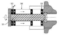
도 1은 제동 요소와 움직이는 요소 사이의 자기(magnetic) 상호작용을 통합하는 일 실시예의 단순화된 정면도(elevation view).
도 2는 대안적인 쌍안정(bistable) 실시예의 단순화된 정면도.
도 3은 상기 쌍안정 실시예에 관한 자기력 상호 작용을 보여주는 그래프.
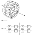
도 4는 코깅(cogging) 토크 접근을 이용하는 대안적인 일 실시예의 사시도와 정면도.
도 5는 턱 토크 접근으로부터의 속도 의존성 결과를 보여주는 2개의 그래프.
도 6은 제동 요소와 움직이는 요소의 턱 토크 접근의 단순화된 정면도.
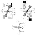
도 7은 회전 자유도를 이용하는 대안적인 일 실시예의 단순화된 정면도.
도 8은 대안적인 캠 경로(cam path) 실시예들의 정면도.
도 9는 대안적인 캠 경로 실시예들의 정면도.
도 10은 대안적인 캠 경로 실시예들의 사시도.
도 11은 대안적인 캠 경로 실시예의 단순화된 사시도.
도 12는 대안적인 캠 경로 실시예의 단순화된 사시도와 정면도.
도 13은 대안적인 캠 경로 실시예의 단순화된 정면도.
도 14는 캠, 기하학적 구조(geometry), 관성 반응, 및 와전류의 조합(combination)을 사용하는 대안적인 실시예의 다양한 정면도.
도 15는 멈춤쇠(pawl)를 사용하는 아트(art) 속도에 민감한 장치의 단순화된 정면도.
도 16은 멈춤쇠를 사용하는 아트 가속에 민감한 장치의 단순화된 정면도.
도 17은 급격한 움직임에 민감한 장치의 단순화된 정면도.
도 18은 얼라인먼트(alignment)가 변하는 도 17의 급격한 움직임에 민감한 장치의 단순화된 정면도.
도 19는 도 17과 도 18의 실시예로부터의 자기 상호 작용의 단순화된 정면도.
도 20은 대안적인 급격한 움직임에 민감한 장치의 단순화된 정면도.1 is a simplified elevation view of an embodiment incorporating magnetic interaction between a braking element and a moving element;
2 is a simplified front view of an alternative bistable embodiment;
3 is a graph showing the magnetic force interaction according to the bistable embodiment.
4 is a perspective view and a front view of an alternative embodiment using a cogging torque approach;
Figure 5 is two graphs showing the speed dependence results from the jaw torque approach.
6 is a simplified front view of a jaw torque approach of a braking element and a moving element;
7 is a simplified front view of an alternative embodiment utilizing rotational degrees of freedom;
8 is a front view of alternative cam path embodiments;
9 is a front view of alternative cam path embodiments;
10 is a perspective view of alternative cam path embodiments;
11 is a simplified perspective view of an alternative cam path embodiment;
12 is a simplified perspective view and a front view of an alternative cam path embodiment;
13 is a simplified front view of an alternative cam path embodiment;
14 is a front view of various alternative embodiments using a combination of cams, geometry, inertial response, and eddy currents;
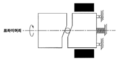
15 is a simplified front view of an art speed sensitive device using a pawl;
16 is a simplified front view of an art acceleration sensitive device using a detent.
17 is a simplified front view of a device sensitive to sudden movements;
Fig. 18 is a simplified front view of the device sensitive to the abrupt movement of Fig. 17 in which the alignment is changed;
Fig. 19 is a simplified front view of magnetic interaction from the embodiment of Figs. 17 and 18;
20 is a simplified front view of an alternative abrupt motion sensitive device;
위에서 주목된 바와 같이, 본 명세서에는 부재들 사이의 상대 속도에서의 멈춤(halt)을 야기하는 부재들 사이의 동적인 반응을 지배하는 시스템, 사용 방법, 및 그러한 시스템을 사용하는 자가 수축 생명줄(SRL)이 설명된다. 자기 상호 작용, 와전류 드래그 힘, 원심력 및/또는 관성력이 지배하는 움직임의 다양한 메커니즘을 제공할 수 있다.As noted above, herein disclosed are systems, methods of use, and self-contracting lifelines (SRLs) that govern the dynamic response between members causing a halt in relative velocity between the members. ) is explained. Magnetic interactions, eddy current drag forces, centrifugal forces, and/or inertial forces can provide various mechanisms of motion.
본 명세서의 목적상, '약(about)' 또는 '대략(approximately)'이라는 용어와 그것들의 문법에 맞는 변화(variation)들은, 기준 수량(quantity), 레벨, 정도, 값, 개수, 빈도수(frequency), 백분율, 치수(dimension), 사이즈(size), 양(amount), 무게 또는 길이까지 30, 25, 20, 15, 10, 9, 8, 7, 6, 5, 4, 3, 2 또는 1%만큼이나 많이 변하는 수량, 레벨, 정도, 값, 개수, 빈도수, 백분율, 치수, 사이즈, 양, 무게 또는 길이를 의미한다.For the purposes of this specification, the terms 'about' or 'approximately' and their grammatical variations refer to a reference quantity, level, degree, value, number, frequency. ), percentage, dimension, size, amount, weight or length up to 30, 25, 20, 15, 10, 9, 8, 7, 6, 5, 4, 3, 2 or 1 means a quantity, level, degree, value, number, frequency, percentage, dimension, size, amount, weight, or length that varies by as much as %.
'실질적으로(substantially)'라고 하는 용어 또는 그것의 문법에 맞는 변화는 적어도 약 50%, 예를 들면 75%, 85%, 95% 또는 98%를 가리킨다.The term 'substantially' or a grammatical change thereof refers to at least about 50%, such as 75%, 85%, 95% or 98%.
'포함한다(comprise)'라는 용어와 그것의 문법에 맞는 변화는 총괄적(inclusive) 의미를 가지는데, 즉 그것이 직접 가리키는 열거된 성분들뿐만 아니라, 다른 특정되지 않은 성분들 또는 요소들을 포함하는 것을 의미하기 위해 취해진다.The term 'comprise' and its grammatical variations have an inclusive meaning, that is, to include the listed components to which it directly refers, as well as other unspecified components or elements. is taken to
'급격한 움직임(jerk)'이라는 용어와 그것의 문법에 맞는 변화는 가속 변화를 가리키고, 보통 정상적인 동작 파라미터들에 대해 비교된 신속하고 갑작스런 가속 변화를 가리킨다.The term 'jerk' and its grammatical change refer to a change in acceleration, usually a rapid and sudden change in acceleration compared to normal operating parameters.
제1 양태에서는 운동학적 관계에 있는 적어도 2개의 부재를 갖는 시스템이 제공되고, 이러한 시스템은 적어도 하나의 추가 부재에 제1 부재를 결합하는 수단을 포함하며, 그렇게 함으로써 부재들 사이의 동기화된 상대적 움직임을 야기하고, 그럴 경우 규정된 시스템 동적 응답에 반응하여 결합이 이루어지고, 그러한 동적 응답은 적어도,In a first aspect there is provided a system having at least two members in kinematic relationship, the system comprising means for coupling the first member to at least one additional member, whereby synchronized relative movement between the members is provided. and, if so, coupling is made in response to a prescribed system dynamic response, such dynamic response being at least:
(a) 부재들 중 하나 이상의 특별한 속도 행위;(a) a particular speeding action of one or more of the members;
(b) 요소들 중 하나 이상의 특별한 가속 행위;(b) a particular accelerating action of one or more of the elements;
(c) 요소들 중 하나 이상의 특별한 급격한 움직임 행위(c) the act of particular rapid movement of one or more of the elements;
중 하나로부터 선택된다.selected from one of
본 발명의 발명자는 실제로 시스템 동적 응답에 기초하여 부재들을 함께 결합하는 것에 관계되는 시스템을 만들었다. 그 목표는 미리 결정된 조건하에서 부재들이 동기화된 움직임을 행하게 하는 것이다.The inventors of the present invention have actually created a system that concerns joining members together based on the system dynamic response. The goal is to cause the members to make synchronized movements under predetermined conditions.
부재들 사이의 결합(coupling)은The coupling between members is
(a) 기계적으로,(a) mechanically;
(b) 자기적으로,(b) magnetically;
(c) 기계적인 것과 자기적인 것의 조합에 의해 달성될 수 있다.(c) can be achieved by a combination of mechanical and magnetic.
결합은 수동적으로 일어날 수 있고, 일단 결합되면 부재들은 결합된 채로 있거나 풀어질 수 있게 결합될 수 있다. 결합은 대신 능동적(active) 수단에 의해 달성될 수 있다.Engagement may occur passively, and once engaged the members may remain engaged or releasably engaged. Coupling may instead be accomplished by active means.
동기화된 움직임은 0인 절대 속도를 가지거나 멈춤 효과(halting effect)가 얻어질 수 있다. 이러한 효과는 예를 들면 추락(fall) 안전 기구에서 모든 움직임이 정지될 필요가 있는 경우에 유용할 수 있다.Synchronized motion may have an absolute velocity of zero or a halting effect may be obtained. This effect may be useful, for example, in a fall safety mechanism where all movement needs to be stopped.
결합은 또한, 와전류 유도된 드래그에 기초하거나 와전류 유도된 드래그에 의해 적어도 영향을 받을 수 있다. 이는 발명자가 경험한 것에 있어서는 본질적인 것은 아니지만, 동적 응답 특징들을 더 조정하기 위해서 유용할 수 있다.Coupling may also be based on or at least affected by eddy current induced drag. This is not essential to the inventor's experience, but may be useful to further tune the dynamic response characteristics.
하나의 구체적인 실시예에서, 부재들 사이의 결합은 제1 부재에 이어져 있고 진동하는 움직임 행위를 가지는, 적어도 하나의 멈춤쇠와, 적어도 하나의 추가 부재 상에 있거나 적어도 하나의 추가 부재인 적어도 하나의 래치 부재 사이의 기계적인 결합을 통해 이루어질 수 있고, 이러한 결합은 규정된 시스템의 동적 응답에 따라 임계 속도에서 발생한다.In one specific embodiment, the engagement between the members is connected to the first member and having an oscillating motion action, at least one detent, and at least one additional member on or at least one additional member This can be achieved through mechanical engagement between the latch members, which engagement takes place at a critical speed according to the dynamic response of the defined system.
멈춤쇠와 래치 부재 사이에는 바이어스(bias) 관계가 존재할 수 있고, 이러한 바이어스는 멈춤쇠의 끌어당김, 밀어냄, 또는 끌어당김과 밀어냄이 번갈아 발생하기 위해 배치된 적어도 하나의 자석을 사용함으로써 달성된다.A bias relationship may exist between the detent and the latch member, which bias may be achieved by using at least one magnet arranged to cause attraction, retraction of the detent, or alternating attraction and retraction of the detent. do.
멈춤쇠와 제1 부재 모두에는 적어도 하나의 자기 요소가 위치할 수 있고, 멈춤쇠와 제1 부재의 회전이 일어날 때, 바이어스가 변하는 것이 이루어지고, 따라서 진동하는 멈춤쇠 움직임이 발생한다. 이러한 멈춤쇠는 제1 부재상에 축 방향으로 장착될 수 있고, 멈춤쇠의 무게중심은 멈춤쇠의 회전축으로부터 오프셋(offset)돌 수 있어, 그로 인해 진동 효과에 더 영향을 미친다.At least one magnetic element may be positioned on both the detent and the first member, and when rotation of the detent and the first member occurs, a bias change is effected, thus resulting in an oscillating detent movement. Such a detent may be axially mounted on the first member, and the center of gravity of the detent may be offset from the axis of rotation of the detent, thereby further affecting the vibration effect.
알 수 있게 되듯이, 멈춤쇠의 진동 정도는 예를 들면 제1 부재와 멈춤쇠(또는 제1 부재와 적어도 하나의 추가 부재) 움직임의 상대 속도(relative rate)에 따라서 달라질 수 있다.As will be appreciated, the degree of vibration of the detent may vary depending on, for example, the relative rate of movement of the first member and the detent (or the first member and the at least one additional member).
멈춤쇠 동적 응답은 또한 그러한 멈춤쇠의 관성을 변화시킴으로써 조정될 수 있다. 위에서 주지된 바와 같이, 멈춤쇠가 이러한 식으로 제1 부재에 연결된다고 하면 멈춤쇠의 질량중심은 멈춤쇠의 회전축으로부터 오프셋될 수 있다. 그러한 멈춤쇠의 부품 또는 부품들은 움직임에 대한 멈춤쇠의 관성을 조정함으로써 시스템의 동적 응답을 조정하도록 무게가 정해질 수 있다(weighted).The detent dynamic response can also be tuned by changing the inertia of such detents. As noted above, if the detent is connected to the first member in this way, the center of mass of the detent may be offset from the axis of rotation of the detent. The part or components of such a detent may be weighted to adjust the dynamic response of the system by adjusting the detent's inertia to movement.
이러한 시스템은 다음과 같이 작용할 수 있다:Such a system can act as follows:
(a) 멈춤쇠가 래치 부재와 결합하도록, 충분한 시간 기간동안 멈춤쇠가 배치된 위치로 움직일 때, 미리 정해진 속도로 결합이 이루어질 수 있고,(a) when the detent moves into the deployed position for a sufficient period of time such that the detent engages the latch member, the engagement can occur at a predetermined rate;
(b) 미리 정해진 속도 미만의 속도로 멈춤쇠가 결합하지 않을 수 있다.(b) The detent may not engage at a speed less than a predetermined speed.
결합은 멈춤쇠가 래치 부재를 간과(skip over)하게 함으로써 회피될 수 있는데, 즉 멈춤쇠는 래치 부재와 간섭하기 위해 충분히 배치되지 않을 수 있다. 이렇게 간과시키는 것은 멈춤쇠의 관성 효과가 극복되고, 래치 부재와 결합하기 위해 멈춤쇠가 충분히 멀리 배치될 때까지 계속될 수 있다.Engagement may be avoided by having the detent skip over the latch member, ie the detent may not be sufficiently positioned to interfere with the latch member. This oversight may continue until the detent's inertial effect is overcome and the detent is positioned far enough away to engage the latch member.
이러한 시스템은 또한,These systems are also
(a) 움직임 속도가 멈춤쇠의 관성 효과를 극복하기에 불충분할 때 멈춤쇠가 결합된 채로 있을 수 있고,(a) the detent may remain engaged when the speed of movement is insufficient to overcome the inertial effect of the detent;
(b) 움직임 속도가 멈춤쇠의 관성 효과를 극복하기에 충분할 때 분리가 발생할 수 있도록 작용할 수 있다.(b) can act to cause separation to occur when the speed of movement is sufficient to overcome the detent's inertial effect.
위에서 주목된 바이어스의 정도는 멈춤쇠의 바라는 동적 응답 거동을 제공하기 위해 구성될 수 있다.The degree of bias noted above can be configured to provide the desired dynamic response behavior of the detent.
대안적인 구체적인 실시예에서는, 부재들 사이의 결합이 규정된 시스템 동적 응답에 따라 관성력 및/또는 인가된 드래그 힘들의 반응 효과에 기초한 기계적인 캠(cam) 시스템에 의해 이루어질 수 있다.In an alternative specific embodiment, engagement between the members may be effected by a mechanical cam system based on the reaction effect of inertial forces and/or applied drag forces in accordance with a defined system dynamic response.
위 시스템에서, 제1 부재와 적어도 하나의 추가 부재가 함께 정렬될 수 있고, 제1 부재와 적어도 하나의 추가 부재 사이에 캠 특징(feature)이 위치할 수 있다. 실제로, 시스템은 적어도 2개의 독립적이지만 움직이는 부재들을 가진다.In the above system, the first member and the at least one additional member may be aligned together, and a cam feature may be positioned between the first member and the at least one additional member. In practice, the system has at least two independent but movable members.
적어도 하나의 추가 부재는, 원동력이 시스템에 인가될 때 제1 부재에 관해서 느려진 움직임을 겪도록 하는 움직임으로 인해, 관성 특징 및/또는 지체되는(retarding) 드래그 중 하나 또는 둘 다를 가지고 구성될 수 있다.The at least one additional member may be configured with one or both of an inertial characteristic and/or a retarding drag due to motion such that it experiences a slowed motion relative to the first member when a motive force is applied to the system. .
제1 부재와 적어도 하나의 추가 부재 사이의 상대 속도는 부재들 사이의 위치 이동(displacement)을 제공할 수 있고, 부재들이 캠 프로필 규정된 움직임 경로(path)로 인해 강제로 분리되게 할 수 있다. 분리란 부재들이 서로에 관해 떨어지게 움직이는 것을 가리킨다.The relative velocity between the first member and the at least one additional member may provide displacement between the members and may force the members to disengage due to the cam profile defined movement path. Separation refers to moving members apart with respect to each other.
적어도 하나의 추가 부재의 움직임은 제1 부재 상에서 또는 제1 부재 주위에서 래치 부재와의 결합을 야기하거나 래치 부재에 적어도 하나의 추가 부재에 대한 적어도 하나의 고정장치(anchor) 결합을 야기할 수 있다.Movement of the at least one additional member may cause engagement with the latch member on or around the first member or cause at least one anchor engagement to the latch member for the at least one additional member. .
알 수 있게 되듯이, 추가 부재를 래치 부재에 결합하는 것은 또한 제1 부재와 추가 부재 사이에서 간접적으로 결합이 이루어지게 한다.As will be seen, coupling the additional member to the latch member also results in indirect engagement between the first member and the additional member.
결합은,bonding is,
(a) 기하학적 래칭 인터페이스(interface);(a) a geometric latching interface;
(b) 자극들의 끌어당김, 또는(b) attraction of stimuli, or
(c) 기하학적 래칭 인터페이스와 자극들의 끌어당김의 조합(combination)을 통해 이루어질 수 있다.(c) through a combination of a geometric latching interface and attraction of the magnetic poles.
또 다른 구체적인 실시예에서는, 부재들 사이에서의 인력을 달성하도록 부재들 사이의 자기력이 구성되는 부재들 사이의 자기력에 결합이 의존할 수 있고, 그러한 인력은 규정된 시스템 동적 응답에 따라 동기화된 상대적 움직임을 가져오는 부재들 사이의 상대적 움직임을 느리게 하거나 멈추기에 충분하다.In another specific embodiment, the coupling may depend on the magnetic force between the members being configured such that the magnetic force between the members is configured to achieve an attractive force between the members, such attraction being a synchronized relative according to a defined system dynamic response. It is sufficient to slow or stop the relative motion between the moving members.
자기력은 부재들 사이에서 작용하는 자극 요소들에 의해 가해질 수 있다. 명세서의 목적상, 자극의 작용은 코깅을 의미한다. 이러한 코깅 시스템은 시스템이 의도된 조건하에서 멈춤 및 보류(hold) 행위를 달성하도록, 연결된 시스템과 임의의 주변 에너지 흡수 수단의 동적인 거동을 고려하여 설계될 수 있다. 자극 요소들은 미리 정해진 조건하에서 효과가 없거나 활발하지 않게 되도록 구성될 수 있다. 자극 행위의 변화는, 예를 들면 자석 또는 자석들을 담고 있는 부품들이나 부재들 사이의 분리 거리를 변화시켜 자기 상호작용력을 감소시킴으로써 이루어질 수 있다.The magnetic force may be applied by stimulating elements acting between the members. For the purposes of the specification, the action of a stimulus means cogging. Such a cogging system can be designed taking into account the dynamic behavior of the connected system and any ambient energy absorbing means, such that the system achieves a hold and hold behavior under the intended conditions. The stimulation elements may be configured to be ineffective or inactive under predetermined conditions. A change in the stimulus behavior can be achieved, for example, by reducing the magnetic interaction force by changing the separation distance between the magnet or the parts or members containing the magnets.
위 시스템은 외부적으로 인가된 원동력이 부재들의 초기 움직임을 가져오지만, 규정된 시스템 동적 응답을 유도하기에 충분한 원동력이 제공된다면 부재들 사이에서 즉시 느리게 하는 행위와 멈춤 행위가 일어나는 잇달아 결합된 시스템일 수 있다.The above system is a sequentially coupled system in which an externally applied motive force causes the initial movement of the members, but an immediate slowing and stopping action occurs between the members if sufficient motive force is provided to induce a defined system dynamic response. can
알 수 있듯이, 위 제1 양태와 설명된 구체적인 실시예들에서는, 부재들이 대체로 선형인 운동학적 관계로 움직일 수 있다. 대안적으로, 그러한 부재들은 대체로 회전하는 운동학적 관계로 움직일 수 있다. 두 행위 모두 가능할 수 있고, 시스템이 사용될 수 있는 장치에 따라 적절할 수 있다. 본 명세서에서 주어지거나 사용된 예들은 회전하는 실시예에서 설명된다. 당업자에게는 선형 등가물 실시예가 알기 쉽다. 또 다른 구체적인 실시예에서는, 부재들이 대체로 회전 운동학적 관계에 있을 수 있고, 미리 정해진 크기를 갖는 원동력이 인가될 때, 부재들이 규정된 시스템 동적 응답에 따라 함께 결합하도록 설계된 원심성 기반 시스템을 통해 부재들 사이의 결합이 이루어질 수 있다.As can be seen, in the first aspect and specific embodiments described above, the members may move in a generally linear kinematic relationship. Alternatively, such members may move in a generally rotating kinematic relationship. Both actions may be possible and may be appropriate depending on the device in which the system may be used. Examples given or used herein are described in a rotating embodiment. Linear equivalent embodiments are readily apparent to those skilled in the art. In yet another specific embodiment, the members may be in a generally rotational kinematic relationship, wherein when a motive force having a predetermined magnitude is applied, the members are brought together via an efferent based system designed to engage them together according to a defined system dynamic response. A bond between them may be made.
부재들에 작용하는 원심력은 적어도 하나의 무게(weight) 또는 무게가 정해진(weighted) 요소 또는 부품을 사용함으로써 영향을 받을 수 있다.The centrifugal force acting on the members may be effected by using at least one weight or weighted element or component.
제1 부재와 적어도 하나의 추가 부재는 함께 정렬될 수 있고, 원심 특징 또는 특징들은 제1 부재와 적어도 하나의 추가 부재 사이에 위치할 수 있다.The first member and the at least one additional member may be aligned together, and the distal feature or features may be located between the first member and the at least one additional member.
부재들의 속도는 원심 특징 또는 특징들의 위치 이동을 촉진할 수 있고, 이는 그 부재들이 적어도 하나의 추가 부재에 가해진 원심력으로 인해 분리되게 촉진한다.The velocity of the members may promote a centrifugal feature or displacement of the features, which promotes the members to separate due to centrifugal force applied to the at least one additional member.
적어도 하나의 추가 부재의 움직임은 제1 부재 상 또는 제1 부재 주위에서의 래치 부재와의 결합과, 적어도 하나의 추가 부재의 적어도 하나의 고정장치를 래치 부재에 결합시키는 것을 야기할 수 있다. 알 수 있듯이, 추가 부재를 래치 부재에 결합시키는 것은 또한 제1 부재와 추가 부재 사이에서 간접적으로 결합이 이루어지게 한다.Movement of the at least one additional member may cause engagement with the latch member on or about the first member and coupling the at least one retainer of the at least one additional member to the latch member. As can be seen, coupling the additional member to the latch member also results in indirect engagement between the first member and the additional member.
결합은,bonding is,
(a) 기하학적 래칭 인터페이스;(a) geometric latching interface;
(b) 자극들의 끌어당김; 또는(b) attraction of stimuli; or
(c) 기하학적 래칭 인터페이스와 자극들의 끌어당김의 조합을 통해 이루어질 수 있다.(c) through a combination of a geometric latching interface and attraction of the poles.
위에서 주목된 것처럼, 동적 응답은 3가지 방식 중 하나로 이루어질 수 있다. 더 자세하게는, 이러한 3가지 행위가 어떻게 일어날 수 있는지의 구체적인 예들은 다음과 같을 수 있다:As noted above, the dynamic response can be done in one of three ways. More specifically, specific examples of how these three behaviors could happen could be:
- 속도에 민감한 장치는 바이어싱 요소의 구속에 대항하여 작용하는 구심력에 의해 활성화되는 멈춤쇠를 사용하여 구성될 수 있다;- speed-sensitive devices can be constructed using detents activated by a centripetal force acting against the constraint of the biasing element;
- 가속도에 민감한 장치는 멈춤쇠 장착 판(plate)의 가속에 응답하여 그것의 피봇(pivot) 주위에서의 멈춤쇠의 회전을 야기하는 멈춤쇠의 관성 거동을 이용할 수 있다;- an acceleration-sensitive device may exploit the inertial behavior of the detent to cause rotation of the detent around its pivot in response to acceleration of the detent mounting plate;
- 한 쌍의 자극 사이에 존재하는 비선형적 전단력 능력(capacity)을 이용함으로써 급격한 움직임에 민감한 장치가 구성될 수 있다.- By exploiting the non-linear shear force capacity that exists between a pair of poles, a device sensitive to sudden movements can be constructed.
알 수 있듯이, 이러한 구성은 변할 수 있고, 위 옵션(option)들은 비제한적인 예로서만 간주되어야 한다.As will be appreciated, such configurations may vary, and the above options should be considered as non-limiting examples only.
제2 양태에서는, 부재들 사이의 상대적인 움직임을 지배하는 방법이 제공되고, 이러한 방법은,In a second aspect, a method of governing relative movement between members is provided, the method comprising:
(a) 실질적으로 본 명세서에서 설명된 것과 같이 시스템을 선택하는 단계;(a) selecting a system substantially as described herein;
(b) 그러한 시스템에서 적어도 하나의 부재의 움직임을 야기하는 원동력을 시스템에 인가하는 단계;(b) applying a motive force to the system causing movement of at least one member in the system;
(c) 규정된 시스템의 동적 응답이 일어날 때 부재들 사이에 결합을 야기하는 단계를 포함한다.(c) causing coupling between the members when the dynamic response of the defined system occurs.
제3 양태에서는, 실질적으로 본 명세서에서 설명된 바와 같이 시스템을 통합하는 자가 수축 생명줄(SRL)이 제공된다.In a third aspect, a self-contracting lifeline (SRL) that incorporates a system substantially as described herein is provided.
위에서 주목된 것처럼, 설명된 장치들은 SRL 장치들에서 사용될 수 있다. 제동 요소를 탐지하고 활성화시키는 능력은 SRL 장치들에 있어서 중요하다.As noted above, the devices described may be used in SRL devices. The ability to detect and activate a braking element is important for SRL devices.
줄(line)의 상태 변화에 응답하는 메커니즘에 의해 잘못된 이벤트(event)의 탐지가 일반적으로 유발된다. 줄의 위치 이동, 속도, 가속도 또는 급격한 움직임(가속도의 변화율), 또는 이들 신호의 조합에 의한 메커니즘들이 잠재적으로 유발될 수 있다.Detection of false events is usually triggered by a mechanism that responds to changes in the state of a line. Mechanisms can be potentially induced by a string's displacement, velocity, acceleration or abrupt movement (rate of change of acceleration), or a combination of these signals.
기존의 SRL들은 일반적으로, 스풀(spool)을 브레이크게 결합하기 위한 래칫(ratchet)과 멈춤쇠 배치를 보통 사용하는, 속도 또는 가속도 메커니즘을 이용한다. 래칫 판 또는 멈춤쇠 세트 중 어느 하나는 회전하는 스풀에 부착될 수 있다.Existing SRLs generally utilize a velocity or acceleration mechanism, usually using a ratchet and detent arrangement to engage the spool to a brake. Either a ratchet plate or a set of detents may be attached to the rotating spool.
선형 구성은 캐리어(움직이는 요소)의 가속도(급격한 움직임)의 변화를 감지하는 수단을 포함할 수 있다. 이러한 캐리어는 주어진 관성을 갖는 알려진 매스(mass)의 라이더(rider)(제동 요소)에 부착될 수 있다. 캐리어에 접촉력이 인가될 때, 라이더와 캐리어는 결합되어 정렬된 채로 있다. 캐리어(급격한 움직임)에 인가된 힘의 변화는 라이더가 관성 효과로 인해 캐리어에 대해 미끄러지게 한다. 이러한 관성 효과는 라이더와 캐리어 사이의 자리 이동을 통해 추적될 수 있다. 캐리어의 가속도가 변할 때, 라이더와 캐리어 사이의 상대적인 자리 이동이 또한 변한다.The linear configuration may include means for sensing a change in acceleration (abrupt movement) of the carrier (moving element). Such a carrier can be attached to a rider (braking element) of a known mass with a given inertia. When a contact force is applied to the carrier, the rider and carrier remain engaged and aligned. A change in force applied to the carrier (a sharp movement) causes the rider to slide relative to the carrier due to inertial effects. These inertial effects can be tracked through seat movement between the rider and carrier. When the acceleration of the carrier changes, the relative displacement between the rider and the carrier also changes.
동일한 원리가 회전 의미(sense)에서 사용될 수 있다. 라이더는 자유롭게 캐리어를 가지고 회전할 수 있다. 캐리어에 인가된 각(angular) 가속도의 변화는 캐리어와 라이더 사이의 상대적인 각 자리 이동으로서 해결될 수 있다.The same principle can be used in the sense of rotation. The rider can freely rotate with the carrier. A change in angular acceleration applied to the carrier can be resolved as a relative angular displacement between the carrier and the rider.
SRL 적용 외에, 다양한 다른 적용예를 위한 장치 및 방법이 사용될 수 있고, 이들의 비제한적인 예에는In addition to SRL application, apparatus and methods for various other applications may be used, non-limiting examples of which include:
오토빌레이(autobelay) 장치;autobelay devices;
회전 터빈에서의 로터;rotors in rotating turbines;
로윙(rowing) 머신, 에피사이클릭(epicyclic) 트레이너, 웨이트 트레이닝 장비와 같은 운동 장비;exercise equipment such as rowing machines, epicyclic trainers, weight training equipment;
롤러 코스터와 다른 오락 탈것들(amusement rides);roller coasters and other amusement rides;
엘리베이터와 에스컬레이터 시스템;elevator and escalator systems;
대피 하강기(evacuation descender)와 화재 탈출 장치;evacuation descenders and fire escape devices;
컨베이어(conveyer) 시스템;conveyor systems;
공장 생산 설비에서의 로터리 드라이브(rotary drive);rotary drives in factory production facilities;
컨베이어 벨트 또는 활송 장치에서의 제동 장치와 같은 재료 취급 장치;material handling devices such as brakes on conveyor belts or chutes;
에너지 흡수체(absorber)에 의한 에너지의 소비를 통해 충돌 약화를 제공하기 위해 에너지 흡수체와 같은 노변(roadside) 안전 시스템들이 시스템에서 연결될 수 있다.Roadside safety systems, such as energy absorbers, may be coupled in the system to provide crash attenuation through consumption of energy by the energy absorber.
차량의 안전 벨트;vehicle seat belts;
집 라인(Zip line)들;Zip lines;
트롤리(trolley)와 운반대(carriage)에 관한 제동 메커니즘;braking mechanisms for trolleys and carriages;
운반 적용예에서의 범프스톱(bumpstop);bumpstops in transport applications;
크레인(crane) 적용예에서의 범프스톱;bumpstops in crane applications;
기계적 드라이브 트레인에서의 토크 또는 힘 제한 장치;torque or force limiting devices in mechanical drive trains;
풍력 터빈에서의 구조상 과부하(overload) 보호;structural overload protection in wind turbines;
구조물, 빌딩, 및 교량에서의 부하 제한 및 에너지 소비의 부하(load) 제어 또는 속도(speed) 제어가 포함된다.load control or speed control of energy consumption and load limiting in structures, buildings, and bridges.
위에서 설명된 시스템, 사용 방법, 및 SRL 장치는 예를 들면 원심력 및/또는 와전류 힘들만에 의존하는 것을 넘는 움직임 제어를 달성하는 대안적인 방식들을 제공한다는 장점을 준다. 게다가, 부품들과, 움직임 제어가 일어나는 비율(rate) 사이의 관계는 본 명세서에서 설명된 실시예들을 사용하여서도 영향을 받을 수 있다.The system, method of use, and SRL apparatus described above have the advantage of providing alternative ways of achieving motion control beyond relying solely on centrifugal and/or eddy current forces, for example. In addition, the relationship between the parts and the rate at which motion control occurs can also be influenced using the embodiments described herein.
위에서 설명된 실시예들은, 또한 넓게는 본 출원 명세서에서 개별적으로 또는 집합적으로 참고되거나 지시된 부품들, 요소들, 및 특징들과, 임의의 2개 이상의 상기 부품, 요소 또는 특징의 임의의 또는 모든 조합들로 이루어진다고 얘기될 수 있고, 이 경우 실시예들이 관련되는 분야에서 알려진 등가물들을 가지는 특정 정수들이 본 명세서에서 언급되어, 그러한 알려진 등가물들은 개별적으로 진술된 것으로서 본 명세서에 통합된 것으로 여겨진다.The embodiments described above also broadly include the parts, elements, and features referenced or indicated, individually or collectively, in this application, and any or all of any two or more of the said parts, elements, or features. In which case the embodiments may be said to consist of all combinations, in which case specific integers having known equivalents in the art to which the embodiments pertain are recited herein, such known equivalents are deemed to be incorporated herein as individually stated.
본 발명이 관련되는 분야에서 알려진 등가물들을 가지는 특정 정수들이 본 명세서에서 언급되고, 그러한 알려진 등가물들은 마치 개별적으로 진술된 것으로서 통합된 것으로 여겨진다.Certain integers having known equivalents in the art to which this invention pertains are recited herein, and such known equivalents are deemed to be incorporated as if individually recited.
작용 예들working examples
이제 위에서 설명된 시스템, 사용 방법, 및 디바이스들을 사용하는 SRL 장치의 예들이 구체적인 예들을 참조하여 설명된다.Examples of an SRL apparatus using the system, method of use, and devices described above are now described with reference to specific examples.
예 1Example 1
아래에는 제동 요소의 움직임에 의해 야기된 자기 래칭의 일반적인 예들이 제공된다.General examples of magnetic latching caused by movement of the braking element are given below.
도 1은 멈춤쇠의 움직임에 의해 야기된 자기 래칭의 일 예를 예시한다. 스풀(12)(제1 부재)과 동심 외부 요소(13)(추가 부재) 사이의 멈춤쇠(11)를 활성화하는 수단으로서 와전류 드래그 힘들(만약 와전류 힘들이 사용되면)을 증가시키거나 대체하기 위해, 영구 자석(10)에 의해 발휘된 직접적인 끌어당기는 힘이 사용될 수 있다. 멈춤쇠(11)가 동심 외부 요소(13)를 가지고 래치될 때에는, 스풀(12)과 동심 외부 요소(13) 사이의 움직임이 동시에 발생된다.1 illustrates an example of magnetic latching caused by movement of a detent. To increase or replace eddy current drag forces (if eddy current forces are used) as a means of activating the
예 2Example 2
본 출원인의 공동 계류중인 출원 NZ619034에서 설명된 튜브 및 실린더(플런저(plunger)) 접근과 함께 쌍안정(bi-stable) 장치(arrangement)가 사용될 수 있다. 이 예에서는, 도 2에 예시된 것처럼, 플런저 축 방향 이동 스트로크(stroke)(52, 53)의 끝에서 브레이크(50)를 래치하고 잠그기 위해, 능동(active) 브레이크 요소/플런저(50)와 리드 스크류(lead screw)(51) 사이의 처음의 상대적 움직임을 지연시키는 수단으로서 플런저(50) 와전류 브레이크 구성이 도시되어 있다. 힘/움직임 상호 작용에 관한 출력(output)이 도 3에서 그래프로 나타나 있고, 이러한 도 3은 플런저 스트로크(52, 53)의 어느 한쪽 끝에서의 힘이 어떻게 높고, 그 후 플런저 스트로크(52, 53)의 이동 단계(phase)를 통해 어떻게 떨어지는지를 보여주며, 이 경우 힘(force)이라고 하는 용어는 옆으로 플런저를 옮기는데 필요한 힘을 가리키고, 움직임은 플런저의 옆으로의 움직임이라는 것을 나타낸다.A bi-stable arrangement may be used with the tube and cylinder (plunger) approach described in Applicant's co-pending application NZ619034. In this example, an active brake element/
예 3Example 3
또 다른 실시예에서는, 코깅 예가 도 4에서 예시된다. 코깅 토크는 일반적으로 화살표 60으로 표시된 것처럼 서로에 관해 회전하는 자극들로부터 생긴다. 이는 F가 진동의 힘/정도(degree)를 가리키고, o가 와전류 제동에 의존하는 브레이크의 저속 로크-오프(lock-off)를 가능하게 할 수 있는 움직임 경로를 가리키는 도 5에 도시된 그래프들에서 가장 잘 보여지는 속도 의존적인 토크 관계를 생기게 한다(가장 높은 래칭 힘이 저속에서 발생한다).In another embodiment, an example of cogging is illustrated in FIG. 4 . Cogging torque generally results from magnetic poles rotating with respect to each other as indicated by
도 6은 자석(60)들이 어떻게 저속에서 정렬하여, 추가 움직임을 멈추게 하는지를 보여준다. 이러한 실시예는 부품들 사이의 상대적 움직임의 완전한 멈춤을 허용하지만, 이 경우 부품 간섭이나 마찰이 없는데, 즉 마찰이 없는 제동이 이루어진다.6 shows how the
도 6은 또한 원심성 실시예를 예시한다. 부재들 중 하나는 정해진 경로를 따라 움직이는 무게가 정해진 볼(ball)들을 포함한다. 최대 회전력으로, 볼들은 무게중심을 바꾸고 그로 인해 시스템의 동적 응답을 변경시킨다.6 also illustrates a centrifugal embodiment. One of the members includes weighted balls moving along a defined path. At maximum torque, the balls change their center of gravity, thereby changing the dynamic response of the system.
예 4Example 4
제동 요소의 자기적 래칭은 또한, 이 예에서는 움직이는 요소(72)(로터)에 대한 제동 요소(71)의 회전축(70)인 프라이머리(primary) 드라이브 축에 수직인 회전 자유도에 대하여 구성될 수 있다. 도 7은 이러한 타입의 시스템의 3가지 실시예를 예시한다. 도 7에는 또한 시스템의 동적 응답을 더 조정하는 바이어스(자석 및/또는 스프링) 사용의 실시예들이 도시되어 있다.The magnetic latching of the brake element can also be configured for a degree of freedom of rotation perpendicular to the primary drive axis, which in this example is the axis of
예 5Example 5
움직이는 요소와 제동 요소 사이의 상대적인 회전은 또한 요소들 사이의 차별적인 속도를 가져오는 관성력 또는 원심력의 사용에 의해 영향을 받을 수 있다. 일 실시예에서, 도 8 내지 13에 예시된 것처럼, 캠 경로(100)를 통한 축 방향 위치 이동을 드라이브하기 위해 차별적인 속도가 사용될 수 있다. 볼 움직임을 제어하기 위해 상이한 프로필이 사용될 수 있고, 따라서 부품들에 작용하는 원심력과 그것들의 움직임 특징들을 바꾼다.The relative rotation between the moving and braking elements can also be affected by the use of inertial or centrifugal forces resulting in differential velocities between the elements. In one embodiment, differential velocities may be used to drive axial positional movement through
도 8 내지 13에 도시된 실시예에서 2개의 절반부들(halves) 사이의 접촉을 유지하는데 필요한 축 방향 부하(load)는 스프링 힘, 자기적 척력에 의해 발생될 수 있거나, 캠(100) 각도를 통해 작용하는 와전류 드래그 토크의 결과로서 발생될 수 있다. 이러한 힘 발생에 대한 추가적인 세부 사항은 도 12와 도 13에 도시되어 있다.The axial load required to maintain contact between the two halves in the embodiment shown in FIGS. 8-13 can be generated by a spring force, a magnetic repulsion force, or by changing the
예 6Example 6
캠의 기하학적 형태, 관성 응답, 및 와전류 드래그 힘-속도 관계의 조합을 이용하는 또 다른 배치가 도 14에 도시되어 있다.Another arrangement using a combination of cam geometry, inertial response, and eddy current drag force-velocity relationship is shown in FIG. 14 .
예 7Example 7
위에서 주목된 것처럼, 제동 요소를 탐지하고 활성화시키는 능력은 SRL 장치에 있어서 중요하다.As noted above, the ability to detect and activate a braking element is important for SRL devices.
추락 사건(fall event)의 탐지는 흔히 줄(line)의 상태 변화에 반응하는 메커니즘에 의해 유발된다. 메커니즘들은 줄의 위치 이동, 속도, 가속도 또는 급격한 움직임(가속도의 변화율)에 의해서 또는 이들 신호의 조합에 의해 잠재적으로 유발될 수 있다.The detection of a fall event is often triggered by a mechanism that responds to a change in the state of the line. Mechanisms can potentially be triggered by a string's displacement, velocity, acceleration, or abrupt movement (rate of change of acceleration) or a combination of these signals.
기존의 SRL들은 보통 일반적으로 스풀을 브레이크에 결합하기 위해 래칫과 멈춤쇠 배치를 사용하는 속도 또는 가속도 메커니즘을 이용한다. 래칫 판이나 멈춤쇠 세트 중 어느 하나가 회전하는 스풀에 부착될 수 있다.Existing SRLs usually use a velocity or acceleration mechanism that typically uses a ratchet and detent arrangement to couple the spool to the brake. Either a ratchet plate or a set of detents can be attached to the rotating spool.
아트(art) 속도에 민감한 장치는 도 15에 예시된 것처럼 바이어싱 요소(스프링)(111)의 구속에 대항하여 작용하는 구심력들에 활성화되는 멈춤쇠(제동 요소)(110)를 사용하여 구성될 수 있다.An art speed sensitive device may be constructed using a detent (braking element) 110 that is activated to centripetal forces acting against the constraint of a biasing element (spring) 111 as illustrated in FIG. 15 . can
아트 가속도에 민감한 장치는 멈춤쇠(112)가 그것의 피벗(113) 주위에서 장착 판에서의 멈춤쇠(112)의 가속에 응답하여 회전을 야기하는 멈춤쇠(112)의 관성 거동을 이용할 수 있다. 이러한 접근은 도 16에 예시되어 있다.An art acceleration sensitive device may utilize the inertial behavior of the
예 8Example 8
급격한 움직임에 민감한 장치는 한 쌍의 자극 사이에 존재하는 비선형 전단력 능력을 이용함으로써 구성될 수 있다.A device sensitive to abrupt motion can be constructed by exploiting the non-linear shear force capability that exists between a pair of poles.
도 17 내지 19에는 선형 구성이 예시되어 있다. 이러한 구성은 캐리어의 가속(급격한 움직임)의 변화를 감지하는 수단을 보여준다. 캐리어(120)는 주어진 관성으로 알려진 질량을 갖는 라이더(130)에 부착된다. 캐리어(120)에 접촉력이 인가될 때, 라이더(130)와 캐리어(120)는 결합되어 정렬된 채로 남아 있다. 캐리어(120)(급격한 움직임)에 인가된 힘의 변화는 라이더(130)로 하여금 관성 효과로 인해 캐리어(120)에 대해 미끄러지게 한다. 이러한 관성 효과는 변위(d)를 통해 추적될 수 있다. 캐리어(120)의 가속도가 변할 때에는 라이더(130)와 캐리어(120) 사이의 상대적 변위가 변한다.17 to 19 illustrate a linear configuration. This configuration shows a means of detecting a change in the acceleration (abrupt movement) of the carrier. A
본 발명의 시스템, 사용 방법, 및 그러한 시스템을 사용하는 자가 수축 생명줄(SRL) 장치의 양태들이 예에 의해서만 설명되었고, 본 명세서의 청구항들의 범주로부터 벗어나지 않으면서 그것들에 대한 수정예와 추가예가 만들어질 수 있다는 점을 인식해야 한다.Aspects of the system, method of use, and self-contracting lifeline (SRL) device using such system have been described by way of example only, and modifications and additions to them may be made without departing from the scope of the claims herein. You have to recognize that you can.
Claims (20)
스풀 상에 줄을 갖는 스풀을 외부 부재 상의 래치에 선택적으로 결합하고, 결합할 시에, 상기 스풀 및 상기 스풀 상의 줄과 상기 외부 부재 사이의 상대적 움직임을 느리게 하거나 멈추도록 구성된 결합기를 포함하고;
상기 결합기는 상기 스풀 상의 줄이 상기 스풀로부터 인출될 때, 상기 스풀에 연결되고 상기 스풀과 회전하는 멈춤쇠를 포함하고;
상기 스풀이 상기 스풀로부터의 줄 인출로 인해 속도 및 가속도 임계치 미만으로 회전할 때, 상기 멈춤쇠는 상기 스풀 회전축에 대하여 방사상으로 외부를 향해 그리고 내부를 향해 진동하고, 상기 결합기는 상기 스풀을 상기 외부 부재에 결합하지 않고; 그리고
상기 스풀이 상기 스풀로부터의 줄 인출로 인해 속도 및 가속도 임계치를 초과하여 회전할 때, 상기 멈춤쇠 또는 그 일부가 상기 외부 부재 상의 기하학적 래칭 인터페이스와 맞물림으로써, 상기 외부 부재 및 스풀을 결합하고, 결합할 시에, 상기 외부 부재와 스풀 사이의 상대적인 움직임을 멈추게 하도록, 상기 결합기의 상기 멈춤쇠는 배치된 위치로 충분히 멀리 방사상으로 외부를 향해 이동하는, 자가 수축 생명줄.As a self-contracting lifeline,
a coupler configured to selectively couple a spool having a string on the spool to a latch on an outer member, and to slow or stop relative movement between the spool and the string on the spool and the outer member upon engagement;
the coupler includes a detent connected to the spool and rotating with the spool when the string on the spool is withdrawn from the spool;
When the spool rotates below a velocity and acceleration threshold due to pull-out of the string from the spool, the detent oscillates radially outwardly and inwardly with respect to the spool axis of rotation, and the coupler engages the spool with the outer member. without binding to; And
when the spool rotates above speed and acceleration thresholds due to pull-out of the string from the spool, the detent or a portion thereof engages a geometrically latching interface on the outer member, thereby engaging the outer member and the spool; When disengaged, the detent of the coupler moves radially outwardly far enough to the deployed position to halt relative movement between the outer member and the spool.
Priority Applications (1)
| Application Number | Priority Date | Filing Date | Title |
|---|---|---|---|
| KR1020227018417A KR102681482B1 (en) | 2014-12-04 | 2015-12-04 | Latch activation between elements |
Applications Claiming Priority (4)
| Application Number | Priority Date | Filing Date | Title |
|---|---|---|---|
| NZ70154514 | 2014-12-04 | ||
| NZ701545 | 2014-12-04 | ||
| KR1020177018534A KR102268419B1 (en) | 2014-12-04 | 2015-12-04 | Latch activation between elements |
| PCT/NZ2015/050205 WO2016089225A1 (en) | 2014-12-04 | 2015-12-04 | Latch activation between elements |
Related Parent Applications (1)
| Application Number | Title | Priority Date | Filing Date |
|---|---|---|---|
| KR1020177018534A Division KR102268419B1 (en) | 2014-12-04 | 2015-12-04 | Latch activation between elements |
Related Child Applications (1)
| Application Number | Title | Priority Date | Filing Date |
|---|---|---|---|
| KR1020227018417A Division KR102681482B1 (en) | 2014-12-04 | 2015-12-04 | Latch activation between elements |
Publications (2)
| Publication Number | Publication Date |
|---|---|
| KR20210077009A true KR20210077009A (en) | 2021-06-24 |
| KR102405797B1 KR102405797B1 (en) | 2022-06-03 |
Family
ID=56092063
Family Applications (3)
| Application Number | Title | Priority Date | Filing Date |
|---|---|---|---|
| KR1020217018617A Expired - Fee Related KR102405797B1 (en) | 2014-12-04 | 2015-12-04 | Latch activation between elements |
| KR1020227018417A Active KR102681482B1 (en) | 2014-12-04 | 2015-12-04 | Latch activation between elements |
| KR1020177018534A Active KR102268419B1 (en) | 2014-12-04 | 2015-12-04 | Latch activation between elements |
Family Applications After (2)
| Application Number | Title | Priority Date | Filing Date |
|---|---|---|---|
| KR1020227018417A Active KR102681482B1 (en) | 2014-12-04 | 2015-12-04 | Latch activation between elements |
| KR1020177018534A Active KR102268419B1 (en) | 2014-12-04 | 2015-12-04 | Latch activation between elements |
Country Status (11)
| Country | Link |
|---|---|
| US (4) | US10774887B2 (en) |
| EP (1) | EP3226978B1 (en) |
| JP (2) | JP2018505634A (en) |
| KR (3) | KR102405797B1 (en) |
| CN (2) | CN106999737B (en) |
| AU (3) | AU2015355671B2 (en) |
| BR (1) | BR112017010692B1 (en) |
| CA (2) | CA3162149C (en) |
| MX (2) | MX381876B (en) |
| SG (1) | SG11201704342RA (en) |
| WO (1) | WO2016089225A1 (en) |
Families Citing this family (26)
| Publication number | Priority date | Publication date | Assignee | Title |
|---|---|---|---|---|
| NZ575464A (en) | 2009-03-10 | 2010-07-30 | Holmes Solutions Ltd | Improvements in and relating to braking mechanisms |
| NZ619034A (en) | 2013-12-16 | 2015-03-27 | Eddy Current Ltd Partnership | An assembly to control relative speed of movement between parts |
| MX364898B (en) | 2014-08-18 | 2019-05-13 | Eddy Current Lp | Latching devices. |
| EP3183803B1 (en) * | 2014-08-18 | 2021-04-14 | Eddy Current Limited Partnership | Tuning of a kinematic relationship between members |
| CA2957635A1 (en) | 2014-08-18 | 2016-02-25 | Eddy Current Limited Partnership | Tuning of a kinematic relationship between members |
| WO2016029059A2 (en) | 2014-08-20 | 2016-02-25 | Mcgowan John Lewis | Eddy current braking device for linear systems |
| EP3227990B1 (en) | 2014-12-04 | 2023-10-11 | Eddy Current Limited Partnership | Eddy current brake configurations |
| CN106999736B (en) | 2014-12-04 | 2021-06-08 | 涡流有限合伙公司 | How to Change Eddy Current Interactions |
| JP6699906B2 (en) | 2014-12-04 | 2020-05-27 | エディ・カーレント・リミテッド・パートナーシップ | Transmission mechanism incorporating eddy current damping and method of transmitting eddy current drag |
| MX391252B (en) | 2014-12-04 | 2025-03-12 | Eddy Current Lp | ENERGY ABSORPTION DEVICE. |
| JP2018505634A (en) * | 2014-12-04 | 2018-02-22 | エディ・カーレント・リミテッド・パートナーシップ | Latch activation between elements |
| CN118566534A (en) | 2015-12-18 | 2024-08-30 | 涡流有限合伙公司 | Variable behavior control mechanism for power system |
| US10022570B2 (en) * | 2016-05-20 | 2018-07-17 | Bailout, LLC | Personal escape device with eddy current braking |
| US10259563B2 (en) * | 2017-05-19 | 2019-04-16 | Kitty Hawk Corporation | Combined fan and motor |
| EP4031254B1 (en) | 2019-09-20 | 2025-07-09 | Trublue LLC | Lock-off descent control systems and devices |
| RU2731825C1 (en) * | 2020-01-09 | 2020-09-08 | федеральное государственное бюджетное образовательное учреждение высшего образования "Уфимский государственный авиационный технический университет" | Self-regulated magnetoelectric damper with opening rotor |
| EP4121176B1 (en) | 2020-03-18 | 2025-03-12 | Trublue LLC | Line dispensing devices |
| CN111498721B (en) * | 2020-04-16 | 2021-09-21 | 杭州藏储科技有限公司 | Industrial winch assembly capable of stalling and self-locking by utilizing centrifugal action |
| CN111550509B (en) * | 2020-05-19 | 2021-04-23 | 湖南驰兴工程建设有限公司 | Stall self-locking mechanism for transmission shaft of household wind driven generator in new energy field |
| WO2022003500A1 (en) * | 2020-07-02 | 2022-01-06 | 3M Innovative Properties Company | Fall-protection apparatus comprising dual-actuatable braking device |
| CN111939496B (en) * | 2020-08-24 | 2021-04-23 | 杭州合泰安防科技有限公司 | Handle type falling protector |
| CN111994815B (en) * | 2020-08-26 | 2021-09-17 | 广东长海建设工程有限公司 | Safety building hoisting accessory |
| CN112366917B (en) * | 2020-11-16 | 2022-02-01 | 合肥工业大学 | Permanent magnet eddy universal transmission device |
| CN112694026A (en) * | 2020-12-21 | 2021-04-23 | 陈群红 | Winch stall self-locking structure utilizing electromagnetic variant principle |
| CN112843519B (en) * | 2021-01-25 | 2021-11-16 | 河南建筑职业技术学院 | Falling protector for high-altitude operation |
| CN114837068B (en) * | 2022-05-30 | 2025-02-14 | 胡雷锋 | An acceleration locking type bridge buffer limiter |
Citations (6)
| Publication number | Priority date | Publication date | Assignee | Title |
|---|---|---|---|---|
| US5441137A (en) * | 1994-05-04 | 1995-08-15 | Eaton Corporation | Clutch with a centrifugally applied ball ramp actuator |
| US5465815A (en) * | 1994-01-10 | 1995-11-14 | Ikegami; Iwao | Magnetic brake |
| GB2352784A (en) * | 1999-08-04 | 2001-02-07 | Moog Inc | Energy-absorbing brake |
| US7014026B2 (en) * | 2001-06-07 | 2006-03-21 | Drussel Wilfley Design, L.L.C. | Manual/automatic pressure control mechanism for centrifugal clutch |
| US20110147125A1 (en) * | 2009-12-23 | 2011-06-23 | D B Industries, Inc. | Fall protection safety device with a braking mechanism |
| US8851235B2 (en) * | 2009-03-10 | 2014-10-07 | Eddy Current Limited Partnership | Braking mechanisms |
Family Cites Families (231)
| Publication number | Priority date | Publication date | Assignee | Title |
|---|---|---|---|---|
| US2058024A (en) | 1934-12-11 | 1936-10-20 | Westinghouse Air Brake Co | Eddy current brake |
| US2122315A (en) | 1936-06-11 | 1938-06-28 | Fosty Leopold | Fire escape |
| US2122312A (en) | 1937-05-25 | 1938-06-28 | Cassion John | Door attachment |
| US2272509A (en) | 1941-06-11 | 1942-02-10 | Cavallo Friedrich | Variable speed friction gear power transmission device |
| US2437871A (en) | 1943-02-09 | 1948-03-16 | Alfred R Wood | Magnetic coupling |
| FR925341A (en) | 1944-06-14 | 1947-09-16 | ||
| US2409009A (en) * | 1945-07-24 | 1946-10-08 | Gen Electric | One-way drive with magnetic lock |
| US2492776A (en) | 1948-08-11 | 1949-12-27 | Martin P Winther | Dynamoelectric machine |
| GB721748A (en) | 1950-06-22 | 1955-01-12 | Baermann Max | Improvements in or relating to permanent magnet brakes or clutches |
| US2807734A (en) | 1954-11-22 | 1957-09-24 | Control Instr Company | Torque transmitting device |
| US2771171A (en) | 1955-07-06 | 1956-11-20 | Lab Equipment Corp | Magnetically activated torque coupling |
| GB908128A (en) * | 1958-06-10 | 1962-10-17 | Andre Duban | Improvements in or relating to ratchet-and-pawl devices |
| FR1418814A (en) | 1964-03-27 | 1965-11-26 | Renault | Improvements to eddy current devices for automatic control of gear changes on vehicles |
| US3447006A (en) | 1967-09-28 | 1969-05-27 | Bliss Co | Electrodynamic brake of magnetic fluid type |
| DE2032935A1 (en) | 1970-07-03 | 1972-01-13 | Kabel Metallwerke Ghh | Device for keeping the speed and tensile force of a wire running off a spool constant |
| JPS5534899Y2 (en) | 1972-12-12 | 1980-08-18 | ||
| JPS4997163A (en) | 1973-01-25 | 1974-09-13 | ||
| US3868005A (en) | 1973-03-14 | 1975-02-25 | Gen Electric | Friction clutch with centrifugal and magnetic speed control |
| DE2402748C2 (en) | 1974-01-21 | 1986-07-03 | Artur 7060 Schorndorf Föhl | Device for initiating the reel shaft blocking of an automatic seat belt retractor |
| US3934446A (en) | 1974-04-16 | 1976-01-27 | Betzalel Avitzur | Methods of and apparatus for production of wire |
| JPS5172657U (en) * | 1974-12-06 | 1976-06-08 | ||
| US3962595A (en) | 1974-12-20 | 1976-06-08 | W. J. Industries, Incorporated | Magnetic particle brake |
| US4078719A (en) | 1976-04-29 | 1978-03-14 | Beckman Instruments, Inc. | Eddy current brake for air driven centrifuge |
| US4093186A (en) | 1976-11-22 | 1978-06-06 | Golden Steven T | Line brake device useful for fire escape |
| JPS53113528U (en) | 1977-02-18 | 1978-09-09 | ||
| GB1599300A (en) | 1977-08-27 | 1981-09-30 | Ferranti Ltd | Speed control |
| US4271944A (en) | 1979-02-12 | 1981-06-09 | Hanson Douglas R | Single revolution torque limiting clutch |
| US4306688A (en) | 1979-02-22 | 1981-12-22 | Injecto Mold, Inc. | Hose reel assembly |
| IT1165923B (en) | 1979-12-12 | 1987-04-29 | Pirelli | CENTRAL SPOOLS CORDING MACHINE |
| US4434971A (en) | 1981-02-11 | 1984-03-06 | Armco Inc. | Drilling rig drawworks hook load overspeed preventing system |
| JPS6034828Y2 (en) * | 1981-03-27 | 1985-10-17 | 小倉クラツチ株式会社 | Clutch brake device |
| JPS5825152U (en) | 1981-08-11 | 1983-02-17 | トヨタ自動車株式会社 | Seat belt energy absorption device |
| US4561605A (en) | 1981-12-25 | 1985-12-31 | Shimano Industrial Company Limited | Brake for a fishing reel |
| US4416430A (en) | 1982-02-01 | 1983-11-22 | Draft Systems, Inc. | Load lowering device |
| US4544111A (en) | 1982-03-09 | 1985-10-01 | Shimano Industrial Company Limited | Brake for a fishing reel |
| JPS59100000A (en) * | 1982-11-30 | 1984-06-08 | Mitsubishi Electric Corp | Starter for load |
| JPS59217589A (en) | 1983-05-26 | 1984-12-07 | 株式会社宮野鉄工所 | slow descent machine |
| US4612469A (en) | 1983-11-10 | 1986-09-16 | Kabushiki Kaisha Sankyo Seiki Seisakusho | Speed governor |
| JPS60259278A (en) | 1984-06-04 | 1985-12-21 | 神鋼電機株式会社 | Falling apparatus using eddy current type brake |
| JPS6115557A (en) | 1984-06-30 | 1986-01-23 | Toshiba Corp | Levitating type conveying apparatus |
| JPH0679620B2 (en) | 1986-02-20 | 1994-10-12 | 株式会社箕浦荷台スタンド製作所 | Resistance imparting device for indoor exercise equipment |
| US4844220A (en) | 1986-02-26 | 1989-07-04 | Shinko Electric Co., Ltd. | Torque limiter |
| US4957644A (en) | 1986-05-13 | 1990-09-18 | Price John T | Magnetically controllable couplings containing ferrofluids |
| GB2192679B (en) * | 1986-05-28 | 1989-12-13 | Barrow Hepburn Equip Ltd | Fall-arrest apparatus |
| JPS6364542A (en) | 1986-09-03 | 1988-03-23 | Sankyo Seiki Mfg Co Ltd | Fan motor |
| US4729525A (en) | 1986-12-12 | 1988-03-08 | Trw Vehicle Safety Systems Inc. | Seat belt retractor with electrically actuatable locking mechanism |
| US5084640A (en) | 1987-03-02 | 1992-01-28 | Unisys Corporation | Eddy current brake with N impedence gaps |
| WO1988008635A1 (en) | 1987-04-30 | 1988-11-03 | Tokyo-Buhin Kogyo Co., Ltd. | Eddy current brake |
| CA1315328C (en) | 1988-10-31 | 1993-03-30 | Kenji Araki | Eddy current retarder |
| US4895317A (en) | 1988-10-31 | 1990-01-23 | Trw Vehicle Safety Systems Inc. | Electrically actuatable locking mechanism for a seat belt retractor |
| US4938435A (en) | 1988-12-30 | 1990-07-03 | Frost Engineering Development Corporation | Personnel lowering device |
| KR910021550A (en) | 1990-02-02 | 1991-12-20 | 발터 쾰러 | Wire brake |
| JPH043733A (en) | 1990-04-20 | 1992-01-08 | Minolta Camera Co Ltd | Image forming device |
| DE4018214A1 (en) | 1990-06-07 | 1991-12-12 | Harting Elektronik Gmbh | DEVICE FOR ELECTROMAGNETICALLY OPERATING A LOCKING MECHANISM OF A BELT REEL |
| JPH07113395B2 (en) | 1991-04-01 | 1995-12-06 | 科学技術庁航空宇宙技術研究所長 | Multi-dimensional damper device |
| US5185542A (en) * | 1991-08-28 | 1993-02-09 | Electroid Company | Electromagnetic pulse operated bi-stable brake |
| JPH0572684A (en) | 1991-09-12 | 1993-03-26 | Fuji Photo Film Co Ltd | Silver halide color photographic sensitive material and method for processing same |
| JP2523883Y2 (en) | 1992-02-24 | 1997-01-29 | 株式会社三協精機製作所 | Governor with pulley |
| US5205386A (en) | 1992-03-05 | 1993-04-27 | United Technologies Corporation | Pawl and ratchet clutch with pawl holdback |
| JPH0584347U (en) | 1992-04-21 | 1993-11-16 | 大成建設株式会社 | Lifeline retractable safety equipment |
| JP3584473B2 (en) | 1992-04-22 | 2004-11-04 | Fdk株式会社 | Magnetic damper device |
| US5272938A (en) | 1992-12-04 | 1993-12-28 | Hsu Chi Hsueh | Flat rim type motor drive mechanism for bicycles |
| DE9300966U1 (en) | 1993-01-25 | 1993-03-11 | Chen, Jeff, Shyong City | Torque control device |
| US5477093A (en) | 1993-05-21 | 1995-12-19 | Magna Force, Inc. | Permanent magnet coupling and transmission |
| US5712520A (en) | 1993-05-21 | 1998-01-27 | Magna Force, Inc. | Permanent magnet braking system |
| US5396140A (en) | 1993-05-28 | 1995-03-07 | Satcon Technology, Corp. | Parallel air gap serial flux A.C. electrical machine |
| US5636804A (en) | 1993-10-05 | 1997-06-10 | Bando Leports, Ltd. | Double-bearing fishing reel |
| US5392881A (en) | 1993-10-06 | 1995-02-28 | The United States Of America As Represented By The Secretary Of The Navy | Device for dampening vibratory motion |
| WO1995016496A1 (en) | 1993-12-14 | 1995-06-22 | Strickler James H | Sport climbing safety device |
| EP0739225B1 (en) * | 1994-01-13 | 1997-12-29 | Barrow Hepburn Sala Limited | Speed responsive coupling device especially for fall arrest apparatus |
| US5722612A (en) | 1994-01-18 | 1998-03-03 | Barrow Hepburn Sala Ltd. | Clutch mechanism for use in safety apparatus |
| JP2929517B2 (en) | 1994-04-01 | 1999-08-03 | ダイワ精工株式会社 | Backlash prevention device for fishing reels |
| US5862891A (en) | 1994-10-28 | 1999-01-26 | Knorr-Bremse Systeme Fur Scheinenfahrzeuge Gmbh | Electromagnetic or permanent-magnetic rail brake |
| US5659578A (en) | 1994-11-23 | 1997-08-19 | At&T Wireless Services, Inc. | High rate Reed-Solomon concatenated trellis coded 16 star QAM system for transmission of data over cellular mobile radio |
| US5862903A (en) | 1994-12-02 | 1999-01-26 | Itt Automotive Electrical Systems, Inc. | Centrifugal clutch for power door locks |
| JP3360281B2 (en) | 1995-03-15 | 2002-12-24 | 株式会社アテックス | Bale diameter variable type roll baler |
| DE29506374U1 (en) | 1995-04-13 | 1996-10-02 | FUNEX AG, Wollerau | Amusement device |
| US5791584A (en) | 1996-01-25 | 1998-08-11 | Kuroiwa; Sachimasa | Tension control unit for filamentous material |
| US5822874A (en) | 1996-04-29 | 1998-10-20 | Nemes; Anne | Automatically retracting chalk line marking tool |
| DE19618903C2 (en) | 1996-05-10 | 1998-03-19 | Knorr Bremse Systeme | Magnetic brake, especially linear eddy current brake |
| US6466119B1 (en) | 1996-09-06 | 2002-10-15 | Chester Drew | Magnetic circuit |
| JPH1098868A (en) | 1996-09-24 | 1998-04-14 | Aichi Steel Works Ltd | Pole layout system for electromagnetic brake |
| JP2834439B2 (en) * | 1996-10-14 | 1998-12-09 | 株式会社京三製作所 | Electric point machine |
| JPH10178717A (en) | 1996-10-15 | 1998-06-30 | Polymer Giya Kk | Safety device for work at high place |
| US5779178A (en) | 1996-11-07 | 1998-07-14 | Rostra Precision Controls, Inc. | Seat belt retractor assembly having magnetically actuated locking mechanism |
| JPH10140536A (en) | 1996-11-12 | 1998-05-26 | Taisei Corp | Underwater mat installation base and underwater mat installation method |
| US5711404A (en) | 1997-02-05 | 1998-01-27 | Lee; Ying-Che | Magnetic adjustable loading device with eddy current |
| US5742986A (en) | 1997-02-13 | 1998-04-28 | Trw Inc. | Seat belt buckle with hall effect locking indicator and method of use |
| JPH10304799A (en) | 1997-03-06 | 1998-11-17 | Ryobi Ltd | Centrifugal braking device for double bearing reel |
| US6086005A (en) | 1997-03-11 | 2000-07-11 | Daiwa Seiko, Inc. | Fishing reel with magnetic force spool rotational-speed control during spool free rotational state |
| EP0976191A1 (en) | 1997-04-14 | 2000-02-02 | David A. Zornes | Magnet coupler having enhanced electromagnetic torque |
| GB2330336A (en) | 1997-10-14 | 1999-04-21 | Alliedsignal Ltd | Energy absorbing device for a seat belt |
| JP3835014B2 (en) | 1997-10-20 | 2006-10-18 | 東亞合成株式会社 | Curable composition |
| JPH11119680A (en) | 1997-10-20 | 1999-04-30 | Ricoh Co Ltd | Liquid crystal display |
| US5928300A (en) | 1997-10-30 | 1999-07-27 | Simula Inc. | Three-axis aircraft crash sensing system |
| JPH11289747A (en) | 1998-04-02 | 1999-10-19 | Isuzu Motors Ltd | Eddy current reducer |
| JP3961668B2 (en) | 1998-05-06 | 2007-08-22 | 美和ロック株式会社 | Sliding door closer |
| CA2280440C (en) | 1998-08-17 | 2005-01-18 | Masayoshi Okamoto | Automotive vehicle body structure demonstrating a controlled reaction load |
| US6042517A (en) | 1998-09-10 | 2000-03-28 | Bell Sports, Inc. | Bicycle trainer magnetic resistance device |
| JP2000116108A (en) | 1998-09-30 | 2000-04-21 | Isuzu Motors Ltd | Eddy current reducer |
| DE19859445C2 (en) | 1998-12-22 | 2001-01-11 | Asm Automation Sensorik Messte | Measuring cable displacement sensor with a longitudinal drive for the cable drum |
| JP3043733B1 (en) * | 1998-12-25 | 2000-05-22 | 株式会社伊藤製作所 | Fall prevention device for work at height |
| DE19951221A1 (en) | 1999-04-01 | 2000-10-05 | Mannesmann Ag | Winding mechanism with housing incorporates electric motor, gear and traction roller fitted on gear output shaft, motor shaft being connected to gear input shaft |
| JP2000316272A (en) * | 1999-04-27 | 2000-11-14 | Topre Corp | Maximum bicycle speed limiter |
| US6051897A (en) | 1999-05-05 | 2000-04-18 | Synchro-Start Products, Inc. | Solenoid actuator with positional feedback |
| JP2001017041A (en) | 1999-07-02 | 2001-01-23 | Akebono Brake Ind Co Ltd | Braking mechanism for reel supported with bearings at both ends |
| DE29912725U1 (en) | 1999-07-21 | 1999-10-07 | Chen, Yu-Peng, Taichung | Magnetic damping device for a training device |
| GB2352645B (en) | 1999-07-21 | 2004-01-14 | Yu-Peng Chen | Magnetic damping device for an exercising device |
| US8180585B2 (en) | 1999-08-26 | 2012-05-15 | Tk Holdings, Inc. | Magnetic crash sensor |
| US6394241B1 (en) | 1999-10-21 | 2002-05-28 | Simula, Inc. | Energy absorbing shear strip bender |
| US20060278478A1 (en) | 1999-11-22 | 2006-12-14 | Pribonic Edward M | Eddy current braking apparatus with adjustable braking force |
| US6293376B1 (en) | 1999-11-22 | 2001-09-25 | Magnetar Technologies Ltd | Apparatus including eddy current braking system |
| US20040055836A1 (en) | 1999-11-22 | 2004-03-25 | Pribonic Edward M. | Eddy current braking apparatus with adjustable braking force |
| GB2357563B (en) | 1999-12-21 | 2002-04-03 | Latchways Plc | Energy absorber |
| US6533083B1 (en) | 2000-02-15 | 2003-03-18 | Magnetar Technologies, Inc | Eddy current braking apparatus |
| CA2400030A1 (en) | 2000-02-15 | 2001-08-23 | Magnetar Technologies Ltd. | Eddy current braking apparatus |
| DE20003513U1 (en) | 2000-02-28 | 2001-07-26 | Wirth Maschinen- und Bohrgeräte-Fabrik GmbH, 41812 Erkelenz | Elevator |
| AU2001273177A1 (en) | 2000-07-06 | 2002-01-21 | Rose Manufacturing Company | Controlled descent device |
| US6412611B1 (en) | 2000-07-17 | 2002-07-02 | Magnetar Technologies, Ltd | Eddy current brake system with dual use conductor fin |
| EP1193724B1 (en) | 2000-09-18 | 2010-02-17 | Isuzu Motors Limited | Eddy current retarder comprising a magnet consisting of an electromagnet and a permanent magnet |
| DE10196701T1 (en) * | 2000-09-29 | 2003-09-04 | Jin Feng | Overrunning clutch |
| US20020162477A1 (en) | 2001-03-02 | 2002-11-07 | Emiliano Palumbo | Dual cable zipline having mechanical ascension and braking systems |
| US7140480B2 (en) * | 2001-06-07 | 2006-11-28 | Drussel Wilfley Design, Llc | Centrifugal clutch and cover mount assembly therefor |
| DE10149112B4 (en) | 2001-10-05 | 2004-11-25 | Robert Bosch Gmbh | Method for determining a triggering decision for restraint devices in a vehicle |
| US6557673B1 (en) | 2001-12-21 | 2003-05-06 | Visteon Global Technologies, Inc. | Integral park brake/eddy current brake assembly |
| US6698554B2 (en) | 2001-12-21 | 2004-03-02 | Visteon Global Technologies, Inc. | Eddy current brake system |
| WO2003055560A1 (en) | 2001-12-28 | 2003-07-10 | Suter Racing International Ag | Abseiling device used as rescue equipment in disaster situations, particularly fires in buildings or tall buildings |
| US7011607B2 (en) | 2002-01-23 | 2006-03-14 | Saris Cycling Group, Inc. | Variable magnetic resistance unit for an exercise device |
| KR100675609B1 (en) | 2002-02-28 | 2007-01-30 | 수미도모 메탈 인더스트리즈, 리미티드 | Eddy current reduction device |
| US6619760B1 (en) | 2002-03-07 | 2003-09-16 | Visteon Global Technologies, Inc. | Closed-loop control algorithm for an eddy current braking system |
| US6723017B2 (en) | 2002-05-09 | 2004-04-20 | Visteon Global Technologies, Inc. | Differential assembly |
| EP2306621A1 (en) | 2002-09-20 | 2011-04-06 | Tai-Her Yang | Axially movable rotor |
| EP3358723A1 (en) | 2002-12-20 | 2018-08-08 | Tai-Her Yang | Electrical machine with structure for axially moving the rotor using centrifugal force |
| TWI298621B (en) | 2003-01-06 | 2008-07-11 | Shimano Kk | Braking device for a dual bearing reel |
| GB2398054B (en) | 2003-01-24 | 2005-08-03 | Ropepower Ltd | Powered rope climbing apparatus |
| US7157021B2 (en) | 2003-02-19 | 2007-01-02 | Archer-Daniels-Midland Company | Methods and compositions for dust and erosion control |
| US6962235B2 (en) | 2003-02-21 | 2005-11-08 | Life-Pack Technologies, Inc. | Apparatus for exterior evacuation from buildings |
| JP4067995B2 (en) | 2003-03-28 | 2008-03-26 | ヒタチグローバルストレージテクノロジーズネザーランドビーブイ | Rotating disk storage device and method for releasing actuator suspension assembly |
| TWM251925U (en) | 2003-08-21 | 2004-12-01 | Jung-Rung Shie | Brake structure for rolling door |
| US7281620B2 (en) | 2003-09-05 | 2007-10-16 | D B Industries, Inc. | Self-retracting lifeline |
| CN100517522C (en) * | 2003-09-27 | 2009-07-22 | 孙奇锋 | Pulse Excitation Bistable Electromagnetic Actuator |
| JP2005119403A (en) | 2003-10-15 | 2005-05-12 | Takata Corp | Seat belt retractor |
| DE102004007434A1 (en) | 2004-02-16 | 2005-09-22 | Minebea Co., Ltd. | Electric machine |
| US7294947B2 (en) | 2004-03-01 | 2007-11-13 | Flux Drive, Inc. | Apparatus for transferring torque magnetically |
| EP1722951B1 (en) | 2004-03-12 | 2020-04-22 | Pregis Intellipack LLC | Hand held dispenser |
| DE102004013836A1 (en) | 2004-03-16 | 2005-10-06 | Bielomatik Leuze Gmbh + Co.Kg | Method for rotary friction welding of plastic parts and apparatus for carrying out the method |
| CN100494040C (en) | 2004-04-29 | 2009-06-03 | 特雷克斯-德马格合资有限公司 | A rope winding system for winding and unwinding steel ropes of cranes |
| US8727078B2 (en) | 2004-05-28 | 2014-05-20 | Velocity Magnetics, Inc. | Selectively incrementally actuated linear eddy current braking system |
| JP2005353123A (en) | 2004-06-08 | 2005-12-22 | Nidec Pigeon Corp | Clamper for disk player |
| GB2415818B (en) | 2004-06-30 | 2008-12-31 | Autoliv Dev | Arrangement for triggering a vehicle safety device |
| US20100211239A1 (en) | 2004-08-06 | 2010-08-19 | Christensen Ladd E | Towrope Winch Dead Start |
| CN1783674A (en) | 2004-11-24 | 2006-06-07 | 乐金电子(天津)电器有限公司 | Cylindrical eddy current shaft connector |
| US7018324B1 (en) | 2004-11-30 | 2006-03-28 | Lily Lin | Magnetic controlled loading device in combination of a power generating set and an adjusting drive mechanism |
| DE102005036570A1 (en) | 2004-12-16 | 2006-07-06 | Steinert Elektromagnetbau Gmbh | Method for decelerating a running metal strip and system for carrying out the method |
| US20060219498A1 (en) | 2005-03-30 | 2006-10-05 | Organek Gregory J | Residual magnetic devices and methods |
| GB0507806D0 (en) | 2005-04-19 | 2005-05-25 | Bm Engineering Uk Ltd | Belay device |
| US8079569B2 (en) | 2005-04-29 | 2011-12-20 | Gerald Lesko | Cable drawworks for a drilling rig |
| US20070001048A1 (en) | 2005-05-18 | 2007-01-04 | Wooster Peter C | Descent device |
| US20070000741A1 (en) | 2005-06-30 | 2007-01-04 | Pribonic Edward M | Axial rotary eddy current brake with adjustable braking force |
| DE102005032694A1 (en) | 2005-07-13 | 2007-01-18 | Forhouse Corp., Shenkang | Magnetic brake controller e.g. for exercising equipment, fastened on flywheel of unit, and has base, rotation device, which rotates on base and which has several connecting sections provided |
| US8565993B2 (en) | 2005-10-11 | 2013-10-22 | Volvo Car Corporation | Enhanced yaw stability control to mitigate a vehicle's abnormal yaw motion due to a disturbance force applied to vehicle body |
| GB2432140A (en) | 2005-11-15 | 2007-05-16 | Latchways Plc | Fall arrest safety device |
| JP2009517603A (en) | 2005-11-25 | 2009-04-30 | コンチネンタル オートモーティヴ ゲゼルシャフト ミット ベシュレンクテル ハフツング | Driving device for automobile |
| US20070135561A1 (en) | 2005-12-08 | 2007-06-14 | Christian Rath | Method of dust abatement |
| US7659802B2 (en) * | 2006-03-15 | 2010-02-09 | Honeywell International Inc. | Bi-stable magnetic latch assembly |
| JP2007276540A (en) | 2006-04-03 | 2007-10-25 | Honda Motor Co Ltd | Vehicle occupant restraint system |
| US7528514B2 (en) | 2006-06-22 | 2009-05-05 | International Business Machines Corporation | Centrifugal magnetic clutch |
| WO2008008225A2 (en) | 2006-07-10 | 2008-01-17 | Sigma Industries, Llc | Retractable lifeline safety device |
| US20080074223A1 (en) | 2006-09-22 | 2008-03-27 | Pribonic Edward M | Reinforcing of permanent magnet arrays |
| US7984796B2 (en) | 2006-10-13 | 2011-07-26 | Magnetar Technologies Corp. | Motion retarding system and method |
| US7843349B2 (en) | 2006-11-03 | 2010-11-30 | D B Industries, Inc. | Retrofittable radio frequency identification connector |
| US20080105503A1 (en) | 2006-11-08 | 2008-05-08 | Pribonic Edward M | Axial rotary eddy current brake with self-adjustable braking force |
| US8037978B1 (en) | 2007-03-13 | 2011-10-18 | Daniel Boren | Eddy current braking system for trolley zip line cable |
| GB2451799B (en) | 2007-05-16 | 2011-12-14 | Latchways Plc | Safety device |
| US8567561B2 (en) | 2007-07-18 | 2013-10-29 | Rescue Reel, Llc | Personal escape device and methods for using same |
| GB0714354D0 (en) | 2007-07-23 | 2007-09-05 | Rapid Rail Internat Ltd | Shock absorber |
| GB0714602D0 (en) | 2007-07-26 | 2007-09-05 | Novathera Ltd | Process |
| US7780146B2 (en) | 2007-09-28 | 2010-08-24 | D B Industries, Inc. | Retrieval assembly |
| BRPI0722115A2 (en) | 2007-10-12 | 2015-10-13 | Latchways Plc | rotational energy absorber, safety device and fall arrest system |
| US8272476B2 (en) | 2007-12-10 | 2012-09-25 | Rapid Egress Descent Systems Ltd. | Descent control device |
| US9016432B2 (en) | 2007-12-10 | 2015-04-28 | Rapid Egress Descent Systems Ltd. | Descent control device |
| JP5122273B2 (en) | 2007-12-28 | 2013-01-16 | 株式会社シマノ | Spool braking device for double-bearing reel |
| EP2247343B1 (en) * | 2008-02-25 | 2017-12-27 | Honeywell Safety Products USA, Inc. | Self-retracting lifeline systems and braking systems therefor |
| WO2009108040A1 (en) | 2008-02-27 | 2009-09-03 | Rapid Vertical Egress System Holding B.V. | Rescue arrangement |
| CN101559267A (en) * | 2008-04-18 | 2009-10-21 | 陈锦鹏 | Device and system for preventing falling |
| US10001804B2 (en) | 2008-08-11 | 2018-06-19 | Force Dimension S.A.R.L. | Force-feedback device and method |
| US20100112224A1 (en) | 2008-10-30 | 2010-05-06 | James A Lott | Methods and formulations for protection ans dust control involving bulk material |
| US20100116922A1 (en) | 2008-11-13 | 2010-05-13 | Reliance Industries, Llc | Cable reel lock for fall arrestor |
| RU106462U1 (en) | 2009-09-15 | 2011-07-10 | Государственное образовательное учреждение высшего профессионального образования "Уфимский государственный авиационный технический университет" | SLOW INDUCTION BRAKE |
| CN102099988B (en) | 2009-10-09 | 2013-04-10 | 丰田自动车株式会社 | Dynamo-electric machine |
| US8226024B2 (en) | 2009-10-14 | 2012-07-24 | D B Industries, Inc. | Self-retracting lifeline with reserve lifeline portion |
| US8556234B2 (en) | 2009-11-13 | 2013-10-15 | Ride Inc. | Single cable descent control device |
| US20110174914A1 (en) | 2010-01-20 | 2011-07-21 | Gimmal Co., Ltd. | Connector device to prevent person from falling |
| GB201002854D0 (en) | 2010-02-19 | 2010-04-07 | Wavefront Reservoir Technologies Ltd | Magnet - operated pulsing tool |
| US20110240403A1 (en) | 2010-03-31 | 2011-10-06 | D B Industries, Inc. | Lifeline Connector for Use with Self-Retracting Lifeline with Disconnectable Lifeline |
| EP2377783A1 (en) | 2010-04-14 | 2011-10-19 | Interroll Holding AG | Transport roller with centrifugally actuated magnetic brake |
| US9199103B2 (en) | 2010-05-12 | 2015-12-01 | Msa Technology, Llc | Fall protection arrangement |
| JP5835215B2 (en) * | 2010-05-17 | 2015-12-24 | 日立金属株式会社 | Coupling device |
| US8469149B2 (en) | 2010-06-07 | 2013-06-25 | D B Industries, Llc | Self-retracting lifeline with disconnectable lifeline |
| WO2012068420A2 (en) | 2010-11-17 | 2012-05-24 | Reliance Industries, Llc | Retractable fall arrester with component assembly and cantilevered main shaft |
| US8424460B2 (en) | 2010-12-28 | 2013-04-23 | Shawn Geoffrey LERNER | Trolley for downhill zip line thrill ride |
| JP5665185B2 (en) | 2011-01-25 | 2015-02-04 | 芦森工業株式会社 | Fall prevention device |
| WO2013003402A2 (en) | 2011-06-29 | 2013-01-03 | Key Safety Systems, Inc. | Fall arrester |
| CN202203305U (en) * | 2011-08-01 | 2012-04-25 | 台州市黄岩华阳机电科技有限公司 | Centrifugal clutch and electric car gear-shifting drive hub with the same |
| WO2013047222A1 (en) | 2011-09-27 | 2013-04-04 | ナブテスコ株式会社 | Vehicle speed control device and vehicle equipped with vehicle speed control device |
| US8601951B2 (en) | 2011-11-11 | 2013-12-10 | Shawn Lerner | Self-cooling trolley |
| US9033115B2 (en) | 2011-11-11 | 2015-05-19 | Shawn Lerner | Zip line braking |
| CN102497085A (en) | 2011-12-23 | 2012-06-13 | 浙江大学 | Permanent-magnet eddy current retarder based on Halbach array |
| US8857578B2 (en) | 2012-01-19 | 2014-10-14 | Technical Film Systems, Inc. | Magnetic brake |
| DE102012202553A1 (en) | 2012-02-20 | 2013-08-22 | Carl Zeiss Smt Gmbh | LITHOGRAPHY DEVICE WITH DAMPING DEVICE |
| CN102627063B (en) * | 2012-03-05 | 2014-05-28 | 江苏大学 | Real-time control device and real-time control method for motion direction of electromagnetic energy-regeneration semi-active suspension |
| US20140110947A1 (en) | 2012-10-24 | 2014-04-24 | Vestas Wind Systems A/S | Wind turbine generator having an eddy current brake, wind turbine having such a generator, and associated methods |
| CN103127627B (en) | 2013-01-30 | 2015-07-08 | 黄柏源 | A double-brake back-and-forth controllable descending device |
| CN103244577A (en) * | 2013-04-27 | 2013-08-14 | 上海法诺格绿色能源系统有限公司 | Overrunning clutch |
| CN103326538B (en) | 2013-06-25 | 2016-01-20 | 常州市博能节能科技有限公司 | Permanent magnet intelligent speed-regulating energy-saving device |
| TWM493137U (en) * | 2013-08-20 | 2015-01-01 | Chih-Chuan Liang | Bistable latching relay and bistable actuator |
| NZ619034A (en) | 2013-12-16 | 2015-03-27 | Eddy Current Ltd Partnership | An assembly to control relative speed of movement between parts |
| US9631684B1 (en) * | 2014-01-06 | 2017-04-25 | The Board Of Trustees Of The Leland Stanford Junior University | Velocity-dependent mechanical and magnetic clutch |
| US10046745B2 (en) | 2014-03-20 | 2018-08-14 | TruBlue LLC | Cable-traversing trolley adapted for use with impact braking |
| EP3183803B1 (en) | 2014-08-18 | 2021-04-14 | Eddy Current Limited Partnership | Tuning of a kinematic relationship between members |
| MX364898B (en) | 2014-08-18 | 2019-05-13 | Eddy Current Lp | Latching devices. |
| CA2957635A1 (en) | 2014-08-18 | 2016-02-25 | Eddy Current Limited Partnership | Tuning of a kinematic relationship between members |
| WO2016029059A2 (en) | 2014-08-20 | 2016-02-25 | Mcgowan John Lewis | Eddy current braking device for linear systems |
| JP2018505634A (en) | 2014-12-04 | 2018-02-22 | エディ・カーレント・リミテッド・パートナーシップ | Latch activation between elements |
| EP3227990B1 (en) | 2014-12-04 | 2023-10-11 | Eddy Current Limited Partnership | Eddy current brake configurations |
| JP6699906B2 (en) | 2014-12-04 | 2020-05-27 | エディ・カーレント・リミテッド・パートナーシップ | Transmission mechanism incorporating eddy current damping and method of transmitting eddy current drag |
| MX391252B (en) | 2014-12-04 | 2025-03-12 | Eddy Current Lp | ENERGY ABSORPTION DEVICE. |
| CN106999736B (en) | 2014-12-04 | 2021-06-08 | 涡流有限合伙公司 | How to Change Eddy Current Interactions |
| CN107709822A (en) * | 2015-03-15 | 2018-02-16 | 福尔摩斯解决方案合伙有限公司 | Energy transfer device and method of use |
| CN118566534A (en) | 2015-12-18 | 2024-08-30 | 涡流有限合伙公司 | Variable behavior control mechanism for power system |
| US9723823B2 (en) | 2016-08-29 | 2017-08-08 | Terry Richardson | Fishing line dispenser |
-
2015
- 2015-12-04 JP JP2017527293A patent/JP2018505634A/en active Pending
- 2015-12-04 BR BR112017010692-2A patent/BR112017010692B1/en active IP Right Grant
- 2015-12-04 CN CN201580065943.5A patent/CN106999737B/en active Active
- 2015-12-04 US US15/532,468 patent/US10774887B2/en active Active
- 2015-12-04 EP EP15864540.8A patent/EP3226978B1/en active Active
- 2015-12-04 KR KR1020217018617A patent/KR102405797B1/en not_active Expired - Fee Related
- 2015-12-04 KR KR1020227018417A patent/KR102681482B1/en active Active
- 2015-12-04 WO PCT/NZ2015/050205 patent/WO2016089225A1/en not_active Ceased
- 2015-12-04 MX MX2017007031A patent/MX381876B/en unknown
- 2015-12-04 AU AU2015355671A patent/AU2015355671B2/en active Active
- 2015-12-04 CA CA3162149A patent/CA3162149C/en active Active
- 2015-12-04 KR KR1020177018534A patent/KR102268419B1/en active Active
- 2015-12-04 CN CN202110187866.8A patent/CN113058170A/en active Pending
- 2015-12-04 SG SG11201704342RA patent/SG11201704342RA/en unknown
- 2015-12-04 CA CA2969407A patent/CA2969407C/en active Active
-
2017
- 2017-06-05 MX MX2020013354A patent/MX2020013354A/en unknown
-
2020
- 2020-08-20 US US16/998,675 patent/US11009089B2/en active Active
-
2021
- 2021-01-28 AU AU2021200520A patent/AU2021200520B2/en active Active
- 2021-04-14 US US17/230,748 patent/US11499596B2/en active Active
- 2021-12-01 JP JP2021195495A patent/JP7667926B2/en active Active
-
2022
- 2022-09-02 US US17/902,656 patent/US12281681B2/en active Active
- 2022-09-08 AU AU2022228143A patent/AU2022228143B2/en active Active
Patent Citations (6)
| Publication number | Priority date | Publication date | Assignee | Title |
|---|---|---|---|---|
| US5465815A (en) * | 1994-01-10 | 1995-11-14 | Ikegami; Iwao | Magnetic brake |
| US5441137A (en) * | 1994-05-04 | 1995-08-15 | Eaton Corporation | Clutch with a centrifugally applied ball ramp actuator |
| GB2352784A (en) * | 1999-08-04 | 2001-02-07 | Moog Inc | Energy-absorbing brake |
| US7014026B2 (en) * | 2001-06-07 | 2006-03-21 | Drussel Wilfley Design, L.L.C. | Manual/automatic pressure control mechanism for centrifugal clutch |
| US8851235B2 (en) * | 2009-03-10 | 2014-10-07 | Eddy Current Limited Partnership | Braking mechanisms |
| US20110147125A1 (en) * | 2009-12-23 | 2011-06-23 | D B Industries, Inc. | Fall protection safety device with a braking mechanism |
Also Published As
Similar Documents
| Publication | Publication Date | Title |
|---|---|---|
| KR102405797B1 (en) | Latch activation between elements | |
| JP7606553B2 (en) | Fall prevention device and method | |
| JP7151047B2 (en) | Equipment and equipment | |
| CN108885225A (en) | A Variable Behavior Control Mechanism for Power System | |
| NZ713668A (en) | A system, method of use and Self Retracting Lifeline (SRL) apparatus | |
| HK40114930A (en) | A variable behaviour control mechanism for a motive system |
Legal Events
| Date | Code | Title | Description |
|---|---|---|---|
| A107 | Divisional application of patent | ||
| PA0104 | Divisional application for international application |
St.27 status event code: A-0-1-A10-A18-div-PA0104 St.27 status event code: A-0-1-A10-A16-div-PA0104 |
|
| PA0201 | Request for examination |
St.27 status event code: A-1-2-D10-D11-exm-PA0201 |
|
| A302 | Request for accelerated examination | ||
| PA0302 | Request for accelerated examination |
St.27 status event code: A-1-2-D10-D17-exm-PA0302 St.27 status event code: A-1-2-D10-D16-exm-PA0302 |
|
| PG1501 | Laying open of application |
St.27 status event code: A-1-1-Q10-Q12-nap-PG1501 |
|
| E902 | Notification of reason for refusal | ||
| PE0902 | Notice of grounds for rejection |
St.27 status event code: A-1-2-D10-D21-exm-PE0902 |
|
| P11-X000 | Amendment of application requested |
St.27 status event code: A-2-2-P10-P11-nap-X000 |
|
| P13-X000 | Application amended |
St.27 status event code: A-2-2-P10-P13-nap-X000 |
|
| E701 | Decision to grant or registration of patent right | ||
| PE0701 | Decision of registration |
St.27 status event code: A-1-2-D10-D22-exm-PE0701 |
|
| GRNT | Written decision to grant | ||
| PA0104 | Divisional application for international application |
St.27 status event code: A-0-1-A10-A18-div-PA0104 St.27 status event code: A-0-1-A10-A16-div-PA0104 |
|
| PR0701 | Registration of establishment |
St.27 status event code: A-2-4-F10-F11-exm-PR0701 |
|
| PR1002 | Payment of registration fee |
St.27 status event code: A-2-2-U10-U12-oth-PR1002 Fee payment year number: 1 |
|
| PG1601 | Publication of registration |
St.27 status event code: A-4-4-Q10-Q13-nap-PG1601 |
|
| PN2301 | Change of applicant |
St.27 status event code: A-5-5-R10-R11-asn-PN2301 |
|
| PN2301 | Change of applicant |
St.27 status event code: A-5-5-R10-R14-asn-PN2301 |
|
| PC1903 | Unpaid annual fee |
St.27 status event code: A-4-4-U10-U13-oth-PC1903 Not in force date: 20250601 Payment event data comment text: Termination Category : DEFAULT_OF_REGISTRATION_FEE |
|
| H13 | Ip right lapsed |
Free format text: ST27 STATUS EVENT CODE: N-4-6-H10-H13-OTH-PC1903 (AS PROVIDED BY THE NATIONAL OFFICE); TERMINATION CATEGORY : DEFAULT_OF_REGISTRATION_FEE Effective date: 20250601 |
|
| PC1903 | Unpaid annual fee |
St.27 status event code: N-4-6-H10-H13-oth-PC1903 Ip right cessation event data comment text: Termination Category : DEFAULT_OF_REGISTRATION_FEE Not in force date: 20250601 |