KR20210150737A - Camera actuator and camera module comprising the same - Google Patents
Camera actuator and camera module comprising the same Download PDFInfo
- Publication number
- KR20210150737A KR20210150737A KR1020200067527A KR20200067527A KR20210150737A KR 20210150737 A KR20210150737 A KR 20210150737A KR 1020200067527 A KR1020200067527 A KR 1020200067527A KR 20200067527 A KR20200067527 A KR 20200067527A KR 20210150737 A KR20210150737 A KR 20210150737A
- Authority
- KR
- South Korea
- Prior art keywords
- holder
- magnetic body
- protrusion
- housing
- disposed
- Prior art date
- Legal status (The legal status is an assumption and is not a legal conclusion. Google has not performed a legal analysis and makes no representation as to the accuracy of the status listed.)
- Granted
Links
Images












Classifications
-
- G—PHYSICS
- G03—PHOTOGRAPHY; CINEMATOGRAPHY; ANALOGOUS TECHNIQUES USING WAVES OTHER THAN OPTICAL WAVES; ELECTROGRAPHY; HOLOGRAPHY
- G03B—APPARATUS OR ARRANGEMENTS FOR TAKING PHOTOGRAPHS OR FOR PROJECTING OR VIEWING THEM; APPARATUS OR ARRANGEMENTS EMPLOYING ANALOGOUS TECHNIQUES USING WAVES OTHER THAN OPTICAL WAVES; ACCESSORIES THEREFOR
- G03B5/00—Adjustment of optical system relative to image or object surface other than for focusing
-
- G—PHYSICS
- G03—PHOTOGRAPHY; CINEMATOGRAPHY; ANALOGOUS TECHNIQUES USING WAVES OTHER THAN OPTICAL WAVES; ELECTROGRAPHY; HOLOGRAPHY
- G03B—APPARATUS OR ARRANGEMENTS FOR TAKING PHOTOGRAPHS OR FOR PROJECTING OR VIEWING THEM; APPARATUS OR ARRANGEMENTS EMPLOYING ANALOGOUS TECHNIQUES USING WAVES OTHER THAN OPTICAL WAVES; ACCESSORIES THEREFOR
- G03B17/00—Details of cameras or camera bodies; Accessories therefor
- G03B17/02—Bodies
-
- H—ELECTRICITY
- H04—ELECTRIC COMMUNICATION TECHNIQUE
- H04N—PICTORIAL COMMUNICATION, e.g. TELEVISION
- H04N23/00—Cameras or camera modules comprising electronic image sensors; Control thereof
- H04N23/50—Constructional details
- H04N23/54—Mounting of pick-up tubes, electronic image sensors, deviation or focusing coils
-
- H—ELECTRICITY
- H04—ELECTRIC COMMUNICATION TECHNIQUE
- H04N—PICTORIAL COMMUNICATION, e.g. TELEVISION
- H04N23/00—Cameras or camera modules comprising electronic image sensors; Control thereof
- H04N23/60—Control of cameras or camera modules
- H04N23/68—Control of cameras or camera modules for stable pick-up of the scene, e.g. compensating for camera body vibrations
- H04N23/682—Vibration or motion blur correction
- H04N23/685—Vibration or motion blur correction performed by mechanical compensation
- H04N23/687—Vibration or motion blur correction performed by mechanical compensation by shifting the lens or sensor position
-
- H04N5/2253—
-
- H04N5/23287—
-
- G—PHYSICS
- G03—PHOTOGRAPHY; CINEMATOGRAPHY; ANALOGOUS TECHNIQUES USING WAVES OTHER THAN OPTICAL WAVES; ELECTROGRAPHY; HOLOGRAPHY
- G03B—APPARATUS OR ARRANGEMENTS FOR TAKING PHOTOGRAPHS OR FOR PROJECTING OR VIEWING THEM; APPARATUS OR ARRANGEMENTS EMPLOYING ANALOGOUS TECHNIQUES USING WAVES OTHER THAN OPTICAL WAVES; ACCESSORIES THEREFOR
- G03B2205/00—Adjustment of optical system relative to image or object surface other than for focusing
- G03B2205/0007—Movement of one or more optical elements for control of motion blur
-
- G—PHYSICS
- G03—PHOTOGRAPHY; CINEMATOGRAPHY; ANALOGOUS TECHNIQUES USING WAVES OTHER THAN OPTICAL WAVES; ELECTROGRAPHY; HOLOGRAPHY
- G03B—APPARATUS OR ARRANGEMENTS FOR TAKING PHOTOGRAPHS OR FOR PROJECTING OR VIEWING THEM; APPARATUS OR ARRANGEMENTS EMPLOYING ANALOGOUS TECHNIQUES USING WAVES OTHER THAN OPTICAL WAVES; ACCESSORIES THEREFOR
- G03B2205/00—Adjustment of optical system relative to image or object surface other than for focusing
- G03B2205/0007—Movement of one or more optical elements for control of motion blur
- G03B2205/0023—Movement of one or more optical elements for control of motion blur by tilting or inclining one or more optical elements with respect to the optical axis
-
- G—PHYSICS
- G03—PHOTOGRAPHY; CINEMATOGRAPHY; ANALOGOUS TECHNIQUES USING WAVES OTHER THAN OPTICAL WAVES; ELECTROGRAPHY; HOLOGRAPHY
- G03B—APPARATUS OR ARRANGEMENTS FOR TAKING PHOTOGRAPHS OR FOR PROJECTING OR VIEWING THEM; APPARATUS OR ARRANGEMENTS EMPLOYING ANALOGOUS TECHNIQUES USING WAVES OTHER THAN OPTICAL WAVES; ACCESSORIES THEREFOR
- G03B2205/00—Adjustment of optical system relative to image or object surface other than for focusing
- G03B2205/0053—Driving means for the movement of one or more optical element
- G03B2205/0069—Driving means for the movement of one or more optical element using electromagnetic actuators, e.g. voice coils
Landscapes
- Physics & Mathematics (AREA)
- General Physics & Mathematics (AREA)
- Engineering & Computer Science (AREA)
- Multimedia (AREA)
- Signal Processing (AREA)
- Lens Barrels (AREA)
- Studio Devices (AREA)
Abstract
Description
본 발명은 카메라 엑추에이터 및 이를 포함하는 카메라 모듈에 관한 것이다. The present invention relates to a camera actuator and a camera module including the same.
카메라는 피사체를 사진이나 동영상으로 촬영하는 장치이며, 휴대용 디바이스, 드론, 차량 등에 장착되고 있다. 카메라 모듈은 영상의 품질을 높이기 위하여 사용자의 움직임에 의한 이미지의 흔들림을 보정하거나 방지하는 영상 안정화(Image Stabilization, IS) 기능, 이미지 센서와 렌즈 사이의 간격을 자동 조절하여 렌즈의 초점거리를 정렬하는 오토포커싱(Auto Focusing, AF) 기능, 줌 렌즈(zoom lens)를 통해 원거리의 피사체의 배율을 증가 또는 감소시켜 촬영하는 주밍(zooming) 기능을 가질 수 있다. A camera is a device that takes a picture or video of a subject, and is mounted on a portable device, a drone, a vehicle, or the like. The camera module has an image stabilization (IS) function that corrects or prevents image shake caused by user movement to improve image quality, and automatically adjusts the distance between the image sensor and the lens to align the focal length of the lens. It may have a zooming function that increases or decreases the magnification of a distant subject through an auto-focusing (AF) function and a zoom lens.
한편, 이미지센서는 고화소로 갈수록 해상도가 높아져 화소(Pixel)의 크기가 작아지게 되는데, 화소가 작아질수록 동일한 시간 동안 받아들이는 빛의 양이 감소하게 된다. 따라서, 고화소 카메라일수록 어두운 환경에서 셔터속도가 느려지면서 나타나는 손떨림에 의한 이미지의 흔들림 현상이 더욱 심하게 나타날 수 있다. 영상 안정화(IS) 기술 중 대표적인 것으로 빛의 경로를 변화시킴으로써 움직임을 보정하는 기술인 광학식 영상 안정화(optical image stabilizer, OIS) 기술이 있다. On the other hand, the resolution of the image sensor increases as the pixel becomes higher and the size of the pixel becomes smaller. As the pixel becomes smaller, the amount of light received for the same time decreases. Therefore, the higher the pixel camera, the more severe the image shake caused by hand shake that occurs when the shutter speed is slowed in a dark environment. As a representative image stabilization (IS) technology, there is an optical image stabilizer (OIS) technology that corrects motion by changing the path of light.
일반적인 OIS 기술에 따르면, 자이로 센서(gyrosensor) 등을 통해 카메라의 움직임을 감지하고, 감지된 움직임을 바탕으로 렌즈를 틸팅 또는 이동시키거나 렌즈와 이미지센서를 포함하는 카메라 모듈을 틸팅 또는 이동시킬 수 있다. 렌즈 또는 렌즈와 이미지센서를 포함하는 카메라 모듈이 OIS를 위하여 틸팅 또는 이동할 경우, 렌즈 또는 카메라 모듈 주변에 틸팅 또는 이동을 위한 공간이 추가적으로 확보될 필요가 있다. According to the general OIS technology, the movement of the camera is detected through a gyrosensor, etc., and the lens is tilted or moved based on the detected movement, or the camera module including the lens and the image sensor can be tilted or moved. . When a lens or a camera module including a lens and an image sensor is tilted or moved for OIS, it is necessary to additionally secure a space for tilting or moving around the lens or camera module.
한편, OIS를 위한 엑추에이터는 렌즈 주변에 배치될 수 있다. 이때, OIS를 위한 엑추에이터는 광축 Z에 대하여 수직하는 두 축, 즉 X축 틸팅을 담당하는 엑추에이터와 Y축 틸팅을 담당하는 엑추에이터를 포함할 수 있다. Meanwhile, an actuator for OIS may be disposed around the lens. In this case, the actuator for OIS may include two axes perpendicular to the optical axis Z, that is, an actuator in charge of tilting the X-axis and an actuator in charge of tilting the Y-axis.
다만, 초슬림 및 초소형의 카메라 모듈의 니즈에 따라 OIS를 위한 엑추에이터를 배치하기 위한 공간 상의 제약이 크며, 렌즈 또는 렌즈와 이미지센서를 포함하는 카메라 모듈 자체가 OIS를 위하여 틸팅 또는 이동할 수 있는 충분한 공간이 보장되기 어려울 수 있다. 또한, 고화소 카메라일수록 수광되는 빛의 양을 늘리기 위해 렌즈의 사이즈가 커지는 것이 바람직한데, OIS를 위한 엑추에이터가 차지하는 공간으로 인하여 렌즈의 사이즈를 키우는데 한계가 있을 수 있다. However, according to the needs of the ultra-slim and ultra-small camera module, there is a large space constraint for arranging the actuator for OIS, and there is sufficient space for tilting or moving the lens or the camera module itself including the lens and image sensor for OIS. It can be difficult to guarantee. In addition, as the high-pixel camera becomes, it is desirable to increase the size of the lens in order to increase the amount of light received.
또한, 카메라 모듈 내에 주밍 기능, AF 기능 및 OIS 기능이 모두 포함되는 경우, OIS용 마그넷과 AF용 또는 Zoom용 마그넷이 서로 근접하게 배치되어 자계 간섭을 일으키는 문제도 있다.In addition, when the zooming function, AF function, and OIS function are all included in the camera module, there is a problem in that the magnet for OIS and the magnet for AF or zoom are disposed close to each other to cause magnetic field interference.
본 발명이 해결하고자 하는 기술적 과제는 초슬림, 초소형 및 고해상 카메라에 적용 가능한 카메라 엑추에이터를 제공하는 것이다. The technical problem to be solved by the present invention is to provide a camera actuator applicable to an ultra-slim, ultra-miniature and high-resolution camera.
본 발명의 실시예에 따른 카메라 엑추에이터는 하우징; 상기 하우징과 결합하는 제1 부재; 광학부재를 포함하는 무버; 상기 제1 부재에 배치되는 제1 자성체; 상기 무버에 배치되는 제2 자성체; 및 상기 무버의 틸팅을 가이드하는 틸팅 가이드부;를 포함하고, 상기 무버는 상기 광학부재와 결합되는 홀더와 상기 홀더와 결합되는 제2 부재를 포함하고, 상기 틸팅 가이드부는 상기 제1 자성체와 상기 제2 자성체의 척력에 의해 상기 제1 부재와 상기 홀더에 밀착된다.A camera actuator according to an embodiment of the present invention includes a housing; a first member coupled to the housing; a mover including an optical member; a first magnetic body disposed on the first member; a second magnetic body disposed on the mover; and a tilting guide part for guiding the tilting of the mover, wherein the mover includes a holder coupled to the optical member and a second member coupled to the holder, and the tilting guide part includes the first magnetic body and the second member. 2 The first member and the holder are closely adhered to each other by the repulsive force of the magnetic body.
상기 제1 부재는 제1 관통홀 및 상기 제1 관통홀에 이격 배치되는 제2 관통홀을 포함하고, 상기 제2 부재는 부재 베이스부; 상기 부재 베이스부의 가장자리에 위치하고 상기 홀더를 향해 연장되는 제1 연장부; 및 상기 제1 연장부와 이격되고 상기 무버를 향해 연장되는 제2 연장부;를 포함할 수 있다.The first member may include a first through hole and a second through hole spaced apart from the first through hole, and the second member may include a member base; a first extension portion positioned at an edge of the member base portion and extending toward the holder; and a second extension spaced apart from the first extension and extending toward the mover.
상기 제1 연장부는 상기 제1 관통홀을 관통하고, 상기 제2 연장부는 상기 제2 관통홀을 관통할 수 있다.The first extension may pass through the first through hole, and the second extension may pass through the second through hole.
상기 제1 부재는, 상기 제1 관통홀 및 상기 제2 관통홀 상부에 배치되는 상부부재; 상기 제1 관통홀 및 상기 제2 관통홀 하부에 배치되는 하부부재; 상기 상부부재와 상기 하부부재를 연결하는 연결부재; 상기 상부부재의 일측에서 홀더를 향해 연장되는 제1 돌기부; 및 상기 상부부재의 타측에서 홀더를 향해 연장되는 제2 돌기부;를 포함하고, 상기 제1 연장부 및 상기 제2 연장부는 상기 상부부재와 상기 하부부재 사이에 배치될 수 있다.The first member may include an upper member disposed above the first through hole and the second through hole; a lower member disposed under the first through hole and the second through hole; a connecting member connecting the upper member and the lower member; a first protrusion extending from one side of the upper member toward the holder; and a second protrusion extending from the other side of the upper member toward the holder, wherein the first extension and the second extension may be disposed between the upper member and the lower member.
실시예에 따른 카메라 엑추에이터는 하우징; 상기 하우징과 결합하는 제1 부재; 홀더를 포함하는 무버; 상기 제1 부재에 배치되는 제1 자성체; 상기 무버에 배치되는 제2 자성체; 및 상기 홀더와 상기 제1 부재 사이에 배치되는 틸팅 가이드부;를 포함하고, 상기 무버는 상기 홀더와 결합되는 제2 부재;를 포함하고, 상기 제1 부재의 일부는 상기 제2 부재와 상기 홀더 사이에 배치되고, 상기 제1 자성체의 제1 면과 상기 제1 면과 마주보는 상기 제2 자성체의 제2 면은 서로 동일 극성을 가질 수 있다.A camera actuator according to an embodiment includes a housing; a first member coupled to the housing; a mover including a holder; a first magnetic body disposed on the first member; a second magnetic body disposed on the mover; and a tilting guide part disposed between the holder and the first member, wherein the mover includes a second member coupled to the holder, wherein a portion of the first member includes the second member and the holder The first surface of the first magnetic material and the second surface of the second magnetic material facing the first surface may have the same polarity.
상기 제2 자성체의 중심과 상기 제2 부재의 중심은 서로 상이한 위치에 있도록 배치될 수 있다.A center of the second magnetic body and a center of the second member may be disposed at different positions from each other.
상기 제2 자성체의 중심은 상기 제2 부재의 중심의 상부 또는 하부에 위치할 수 있다.The center of the second magnetic body may be located above or below the center of the second member.
상기 제2 자성체의 면적은 상기 제1 자성체의 면적보다 크고, 상기 제1 자성체는 상기 제2 자성체의 양 끝 단을 광축 방향으로 연장하는 가상의 직선 내 위치할 수 있다.An area of the second magnetic material may be greater than an area of the first magnetic material, and the first magnetic material may be positioned within a virtual straight line extending both ends of the second magnetic material in an optical axis direction.
실시예에 따른 카메라 엑추에이터는 하우징; 상기 하우징과 결합하는 제1 부재; 상기 제1 부재에 배치되는 제1 자성체; 상기 제1 자성체에 대응하는 제2 자성체; 상기 제2 자성체가 배치되는 제2 부재; 상기 제2 부재와 결합하는 홀더; 및 상기 홀더와 상기 제1 부재 사이에 배치되는 틸팅 가이드부;를 포함하고, 상기 제1 부재의 일부는 상기 제2 부재와 상기 홀더 사이에 배치된다.A camera actuator according to an embodiment includes a housing; a first member coupled to the housing; a first magnetic body disposed on the first member; a second magnetic body corresponding to the first magnetic body; a second member on which the second magnetic body is disposed; a holder coupled to the second member; and a tilting guide part disposed between the holder and the first member, wherein a portion of the first member is disposed between the second member and the holder.
상기 제1 자성체와 제2 자성체는 서로 동일 극성으로 대향할 수 있다.The first magnetic material and the second magnetic material may face each other with the same polarity.
본 발명의 실시예에 따르면, 초슬림, 초소형 및 고해상 카메라에 적용 가능한 카메라 엑추에이터를 제공할 수 있다. 특히, 카메라 모듈의 전체적인 사이즈를 늘리지 않으면서도 OIS용 엑추에이터를 효율적으로 배치할 수 있다. According to an embodiment of the present invention, it is possible to provide a camera actuator applicable to an ultra-slim, ultra-small and high-resolution camera. In particular, the actuator for OIS can be efficiently arranged without increasing the overall size of the camera module.
본 발명의 실시예에 따르면, X축 방향의 틸팅 및 Y축 방향의 틸팅이 서로 자계 간섭을 일으키지 않으며, 안정적인 구조로 X축 방향의 틸팅 및 Y축 방향의 틸팅이 구현될 수 있고, AF용 또는 주밍용 엑추에이터와도 서로 자계 간섭을 일으키지 않아 정밀한 OIS 기능을 실현할 수 있다. According to an embodiment of the present invention, tilting in the X-axis direction and tilting in the Y-axis direction do not cause magnetic field interference with each other, and tilting in the X-axis direction and tilting in the Y-axis direction can be implemented with a stable structure, and for AF or Even with the actuator for zooming, it does not cause magnetic field interference, so precise OIS function can be realized.
본 발명의 실시예에 따르면, 렌즈의 사이즈 제한을 해소하여 충분한 광량 확보가 가능하며, 저소비 전력의 OIS 구현이 가능하다. According to an embodiment of the present invention, it is possible to secure a sufficient amount of light by eliminating the size limitation of the lens, and it is possible to implement OIS with low power consumption.
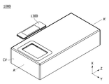
도 1은 실시예에 따른 카메라 모듈의 사시도이고,
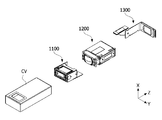
도 2는 실시예에 따른 카메라 모듈의 분해 사시도이고,
도 3는 도 1에서 AA’로 바라본 단면도이고,
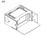
도 4는 실시에에 따른 제1 카메라 엑추에이터의 사시도이고,
도 5는 실시예에 따른 제1 카메라 엑추에이터의 분해 사시도이고,
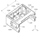
도 6a는 실시예에 따른 제1 카메라 엑추에이터의 제1 하우징의 사시도이고,
도 6b는 도 6a와 상이한 방향의 사시도이고,
도 6c는 실시예에 따른 제1 카메라 엑추에이터의 제1 하우징의 정면도이고,
도 7은 실시예에 따른 제1 카메라 엑추에이터의 광학부재의 사시도이고,
도 8a는 실시예에 따른 제1 카메라 엑추에이터의 홀더의 사시도이고,
도 8b는 실시예에 따른 제1 카메라 엑추에이터의 홀더의 저면도이고,
도 8c는 실시예에 따른 제1 카메라 엑추에이터의 홀더의 정면도이고,
도 8d는 실시예에 따른 제1 카메라 엑추에이터의 제2 부재의 후면도이고,
도 8e는 실시예에 따른 제1 카메라 엑추에이터의 제2 부재의 저면도이고,
도 9a는 실시예에 따른 제1 카메라 엑추에이터의 틸팅 가이드부의 사시도이고,
도 9b는 도 9a와 상이한 방향의 사시도이고,
도 9c는 도 9a에서 FF’로 바라본 단면도이고,
도 10은 실시예에 따른 제1 카메라 엑추에이터의 제1 구동부를 도시한 도면이고,
도 11a는 실시예에 따른 제1 카메라 엑추에이터의 사시도이고,
도 11b는 도 11a에서 PP’로 바라본 단면도이고,
도 11c는 도 11a에서 QQ’로 바라본 단면도이고,
도 12a는 실시예에 따른 제1 카메라 엑추에이터의 사시도이고,
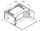
도 12b는 도 12a에서 SS’로 바라본 단면도이고,
도 12c는 도 12b에 도시된 제1 카메라 엑추에이터의 이동의 예시도이다.
도 13a는 도 12a에서 RR’로 바라본 단면도이고,
도 13b는 도 13a에 도시된 제1 카메라 엑추에이터의 이동의 예시도이고,
도 14는 실시예에 따른 제1 카메라 엑추에이터의 조립 순서를 설명하는 도면이고,
도 15는 실시예에 따른 제2 카메라 엑추에이터의 사시도이고,
도 16는 실시예에 따른 제2 카메라 엑추에이터의 분해 사시도이고,
도 17은 도 15에서 DD’로 바라본 단면도이고,
도 18는 도 15에서 EE’로 바라본 단면도이고,
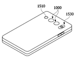
도 19는 실시예에 따른 카메라 모듈이 적용된 이동 단말기의 사시도이고,
도 20은 실시예에 따른 카메라 모듈이 적용된 차량의 사시도이다.1 is a perspective view of a camera module according to an embodiment;
2 is an exploded perspective view of a camera module according to an embodiment;
3 is a cross-sectional view taken along line AA' in FIG. 1;
4 is a perspective view of a first camera actuator according to an embodiment;
5 is an exploded perspective view of a first camera actuator according to an embodiment;
6A is a perspective view of a first housing of a first camera actuator according to an embodiment;
Figure 6b is a perspective view in a different direction from Figure 6a,
6C is a front view of a first housing of a first camera actuator according to an embodiment;
7 is a perspective view of an optical member of a first camera actuator according to an embodiment;
8A is a perspective view of a holder of a first camera actuator according to an embodiment;
8B is a bottom view of the holder of the first camera actuator according to the embodiment;
8C is a front view of the holder of the first camera actuator according to the embodiment;
8D is a rear view of a second member of the first camera actuator according to the embodiment;
8E is a bottom view of a second member of the first camera actuator according to the embodiment;
9A is a perspective view of a tilting guide part of a first camera actuator according to an embodiment;
9B is a perspective view in a different direction from FIG. 9A;
9C is a cross-sectional view taken along FF' in FIG. 9A;
10 is a view illustrating a first driving unit of a first camera actuator according to an embodiment;
11A is a perspective view of a first camera actuator according to an embodiment;
11B is a cross-sectional view taken from PP' in FIG. 11A;
11c is a cross-sectional view taken along QQ' in FIG. 11a;
12A is a perspective view of a first camera actuator according to an embodiment;
12B is a cross-sectional view taken along SS' in FIG. 12A;
12C is an exemplary diagram of movement of the first camera actuator shown in FIG. 12B .
13A is a cross-sectional view taken along RR' in FIG. 12A;
13B is an exemplary view of the movement of the first camera actuator shown in FIG. 13A;
14 is a view for explaining the assembly sequence of the first camera actuator according to the embodiment;
15 is a perspective view of a second camera actuator according to an embodiment;
16 is an exploded perspective view of a second camera actuator according to the embodiment;
17 is a cross-sectional view taken along DD' in FIG. 15;
18 is a cross-sectional view taken along EE' in FIG. 15;
19 is a perspective view of a mobile terminal to which a camera module according to an embodiment is applied;
20 is a perspective view of a vehicle to which a camera module according to an embodiment is applied.
본 발명은 다양한 변경을 가할 수 있고 여러 가지 실시예를 가질 수 있는 바, 특정 실시예들을 도면에 예시하고 설명하고자 한다. 그러나, 이는 본 발명을 특정한 실시 형태에 대해 한정하려는 것이 아니며, 본 발명의 사상 및 기술 범위에 포함되는 모든 변경, 균등물 내지 대체물을 포함하는 것으로 이해되어야 한다. Since the present invention may have various changes and may have various embodiments, specific embodiments will be illustrated and described in the drawings. However, this is not intended to limit the present invention to specific embodiments, and it should be understood to include all modifications, equivalents and substitutes included in the spirit and scope of the present invention.
제2, 제1 등과 같이 서수를 포함하는 용어는 다양한 구성요소들을 설명하는데 사용될 수 있지만, 구성요소들은 용어들에 의해 한정되지는 않는다. 용어들은 하나의 구성요소를 다른 구성요소로부터 구별하는 목적으로만 사용된다. 예를 들어, 본 발명의 권리 범위를 벗어나지 않으면서 제2 구성요소는 제1 구성요소로 명명될 수 있고, 유사하게 제1 구성요소도 제2 구성요소로 명명될 수 있다. 및/또는 이라는 용어는 복수의 관련된 기재된 항목들의 조합 또는 복수의 관련된 기재된 항목들 중의 어느 항목을 포함한다. Terms including an ordinal number such as second, first, etc. may be used to describe various elements, but the elements are not limited by the terms. The terms are used only for the purpose of distinguishing one component from another. For example, without departing from the scope of the present invention, the second component may be referred to as the first component, and similarly, the first component may also be referred to as the second component. and/or includes a combination of a plurality of related listed items or any of a plurality of related listed items.
어떤 구성요소가 다른 구성요소에 "연결되어" 있다거나 "접속되어" 있다고 언급된 때에는, 그 다른 구성요소에 직접적으로 연결되어 있거나 또는 접속되어 있을 수도 있지만, 중간에 다른 구성요소가 존재할 수도 있다고 이해되어야 할 것이다. 반면에, 어떤 구성요소가 다른 구성요소에 "직접 연결되어" 있다거나 "직접 접속되어" 있다고 언급된 때에는, 중간에 다른 구성요소가 존재하지 않는 것으로 이해되어야 할 것이다. When an element is referred to as being “connected” or “connected” to another element, it is understood that it may be directly connected or connected to the other element, but other elements may exist in between. it should be On the other hand, when it is said that a certain element is "directly connected" or "directly connected" to another element, it should be understood that the other element does not exist in the middle.
본 출원에서 사용한 용어는 단지 특정한 실시예를 설명하기 위해 사용된 것으로, 본 발명을 한정하려는 의도가 아니다. 단수의 표현은 문맥상 명백하게 다르게 뜻하지 않는 한, 복수의 표현을 포함한다. 본 출원에서, "포함하다" 또는 "가지다" 등의 용어는 명세서상에 기재된 특징, 숫자, 단계, 동작, 구성요소, 부품 또는 이들을 조합한 것이 존재함을 지정하려는 것이지, 하나 또는 그 이상의 다른 특징들이나 숫자, 단계, 동작, 구성요소, 부품 또는 이들을 조합한 것들의 존재 또는 부가 가능성을 미리 배제하지 않는 것으로 이해되어야 한다. The terms used in the present application are only used to describe specific embodiments, and are not intended to limit the present invention. The singular expression includes the plural expression unless the context clearly dictates otherwise. In the present application, terms such as “comprise” or “have” are intended to designate that a feature, number, step, operation, component, part, or combination thereof described in the specification exists, but one or more other features It should be understood that this does not preclude the existence or addition of numbers, steps, operations, components, parts, or combinations thereof.
다르게 정의되지 않는 한, 기술적이거나과학적인 용어를 포함해서 여기서 사용되는 모든 용어들은 본 발명이 속하는 기술 분야에서 통상의 지식을 가진 자에 의해 일반적으로 이해되는 것과 동일한 의미를 가지고 있다. 일반적으로 사용되는 사전에 정의되어 있는 것과 같은 용어들은 관련 기술의 문맥 상 가지는 의미와 일치하는 의미를 가지는 것으로 해석되어야 하며, 본 출원에서 명백하게 정의하지 않는 한, 이상적이거나 과도하게 형식적인 의미로 해석되지 않는다. Unless defined otherwise, all terms used herein, including technical or scientific terms, have the same meaning as commonly understood by one of ordinary skill in the art to which this invention belongs. Terms such as those defined in commonly used dictionaries should be interpreted as having a meaning consistent with the meaning in the context of the related art, and should not be interpreted in an ideal or excessively formal meaning unless explicitly defined in the present application. does not
이하, 첨부된 도면을 참조하여 실시예를 상세히 설명하되, 도면 부호에 관계없이 동일하거나 대응하는 구성 요소는 동일한 참조 번호를 부여하고 이에 대한 중복되는 설명은 생략하기로 한다. Hereinafter, the embodiment will be described in detail with reference to the accompanying drawings, but the same or corresponding components are given the same reference numerals regardless of reference numerals, and overlapping descriptions thereof will be omitted.
도 1은 실시예에 따른 카메라 모듈의 사시도이고, 도 2는 실시예에 따른 카메라 모듈의 분해 사시도이고, 도 3는 도 1에서 AA’로 바라본 단면도이다.1 is a perspective view of a camera module according to an embodiment, FIG. 2 is an exploded perspective view of a camera module according to an embodiment, and FIG. 3 is a cross-sectional view taken along line AA′ in FIG. 1 .
도 1 및 도 2를 참조하면, 실시예에 따른 카메라 모듈(1000)은 커버(CV), 제1 카메라 엑추에이터(1100), 제2 카메라 엑추에이터(1200), 및 회로 기판(1300)으로 이루어질 수 있다. 여기서, 제1 카메라 엑추에이터(1100)는 제1 엑추에이터로, 제2 카메라 엑추에이터(1200)는 제2 엑추에이터로 혼용될 수 있다.1 and 2 , the
커버(CV)는 제1 카메라 엑추에이터(1100) 및 제2 카메라 엑추에이터(1200)를 덮을 수 있다. 커버(CV)에 의해 제1 카메라 엑추에이터(1100)와 제2 카메라 엑추에이터(1200) 간의 결합력이 개선될 수 있다.The cover CV may cover the
나아가, 커버(CV)는 전자파 차단을 수행하는 재질로 이루어질 수 있다. 이에, 커버(CV) 내의 제1 카메라 엑추에이터(1100)와 제2 카메라 엑추에이터(1200)를 용이하게 보호할 수 있다.Furthermore, the cover CV may be made of a material that blocks electromagnetic waves. Accordingly, the
그리고 제1 카메라 엑추에이터(1100)는 OIS(Optical Image Stabilizer) 엑추에이터일 수 있다. 예컨대, 제1 카메라 엑추에이터(1100)는 광축에 대해 수직한 방향으로 광학 부재를 이동시킬 수 있다.In addition, the
제1 카메라 엑추에이터(1100)는 소정의 경통(미도시)에 배치된 고정 초점거리 렌즈(fixed focal length les)를 포함할 수 있다. 고정 초점거리 렌즈(fixed focal length les)는“단일 초점거리 렌즈” 또는 “단(單) 렌즈”로 칭해질 수도 있다.The
제1 카메라 엑추에이터(1100)는 광의 경로를 변경할 수 있다. 실시예로, 제1 카메라 엑추에이터(1100)는 내부의 광학 부재(예컨대, 프리즘 또는 미러)를 통해 광 경로를 수직으로 변경할 수 있다. 이러한 구성에 의하여, 이동 단말기의 두께가 감소하더라도 광 경로의 변경을 통해 이동 단말기의 두께보다 큰 렌즈 구성이 이동 단말기 내에 배치되어 배율, 오토 포커싱(AF) 및 OIS 기능이 수행될 수 있다.The
다만, 이에 한정되는 것은 아니며 제1 카메라 엑추에이터(1100)는 광 경로를 복수 회 수직 또는 소정의 각도로 변경할 수 있다.However, the present invention is not limited thereto, and the
제2 카메라 엑추에이터(1200)는 제1 카메라 엑추에이터(1100) 후단에 배치될 수 있다. 제2 카메라 엑추에이터(1200)는 제1 카메라 엑추에이터(1100)와 결합할 수 있다. 그리고 상호 간의 결합은 다양한 방식에 의해 이루어질 수 있다.The
또한, 제2 카메라 엑추에이터(1200)는 줌(Zoom) 엑추에이터 또는 AF(Auto Focus) 엑추에이터일 수 있다. 예를 들어, 제2 카메라 엑추에이터(1200)는 하나 또는 복수의 렌즈를 지지하며 소정의 제어부의 제어신호에 따라 렌즈를 움직여 오토 포커싱 기능 또는 줌 기능을 수행할 수 있다.Also, the
그리고 하나 또는 복수의 렌즈는 독립 또는 개별적으로 광축 방향을 따라 이동하여 and one or a plurality of lenses are moved independently or individually along the optical axis direction to
회로 기판(1300)은 제2 카메라 엑추에이터(1200) 후단에 배치될 수 있다. 회로 기판(1300)은 제2 카메라 엑추에이터(1200) 및 제1 카메라 엑추에이터(1100)와 전기적으로 연결될 수 있다. 또한, 회로 기판(1300)은 복수 개일 수 있다. The
실시예에 따른 카메라 모듈은 단일 또는 복수의 카메라 모듈로 이루어질 수도 있다. 예컨대, 복수의 카메라 모듈은 제1 카메라 모듈과 제2 카메라 모듈을 포함할 수 있다.The camera module according to the embodiment may be formed of a single or a plurality of camera modules. For example, the plurality of camera modules may include a first camera module and a second camera module.
그리고 제1 카메라 모듈은 단일 또는 복수의 엑추에이터를 포함할 수 있다. 예를 들어, 제1 카메라 모듈은 제1 카메라 엑추에이터(1100)와 제2 카메라 엑추에이터(1200)를 포함할 수 있다. And the first camera module may include a single or a plurality of actuators. For example, the first camera module may include a
그리고 제2 카메라 모듈은 소정의 하우징(미도시)에 배치되고, 렌즈부를 구동할 수 있는 엑추에이터(미도시)를 포함할 수 있다. 엑추에이터는 보이스 코일 모터, 마이크로 엑추에이터, 실리콘 엑추에이터 등일 수 있고, 정전방식, 써멀 방식, 바이 모프 방식, 정전기력 방식 등 여러 가지로 응용될 수 있으며 이에 한정되는 것은 아니다. 또한, 본 명세서에서 카메라 엑추에이터는 엑추에이터 등으로 언급할 수 있다. 또한, 복수 개의 카메라 모듈로 이루어진 카메라 모듈은 이동 단말기 등 다양한 전자 기기 내에 실장될 수 있다.In addition, the second camera module is disposed in a predetermined housing (not shown) and may include an actuator (not shown) capable of driving the lens unit. The actuator may be a voice coil motor, a micro actuator, a silicon actuator, etc., and may be applied in various ways, such as an electrostatic method, a thermal method, a bimorph method, an electrostatic force method, and the like, but is not limited thereto. Also, in this specification, the camera actuator may be referred to as an actuator or the like. In addition, a camera module including a plurality of camera modules may be mounted in various electronic devices such as a mobile terminal.
도 3을 참조하면, 실시예에 따른 카메라 모듈은 OIS 기능을 하는 제1 카메라 엑추에이터(1100) 및 주밍(zooming) 기능 및 AF 기능을 하는 제2 카메라 엑추에이터(1200)를 포함할 수 있다.Referring to FIG. 3 , the camera module according to the embodiment may include a
광은 제1 카메라 엑추에이터(1100)의 상면에 위치한 개구 영역을 통해 카메라 모듈 또는 제1 카메라 엑추에이터 내로 입사될 수 있다. 즉, 광은 광축 방향(예컨대, X축 방향)을 따라 제1 카메라 엑추에이터(1100)의 내부로 입사되고, 광학 부재를 통해 광경로가 수직 방향(예컨대, Z축 방향)으로 변경될 수 있다. 그리고 광은 제2 카메라 엑추에이터(1200)를 통과하고, 제2 카메라 엑추에이터(1200)의 일단에 위치하는 이미지 센서(IS)로 입사될 수 있다(PATH).Light may be incident into the camera module or the first camera actuator through an opening area located on the upper surface of the
본 명세서에서, 저면은 제1 방향에서 일측을 의미한다. 그리고 제1 방향은 도면 상 X축 방향이고 제2 축 방향 등과 혼용될 수 있다. 제2 방향은 도면 상 Y축 방향이며 제1 축 방향 등과 혼용될 수 있다. 제2 방향은 제1 방향과 수직한 방향이다. 또한, 제3 방향은 도면 상 Z축 방향이고, 제3 축 방향 등과 혼용될 수 있다. 그리고 제3 방향은 제1 방향 및 제2 방향에 모두 수직한 방향이다. 여기서, 제3 방향(Z축 방향)은 광축의 방향에 대응하며, 제1 방향(X축 방향)과 제2 방향(Y축 방향)은 광축에 수직한 방향이며 제2 카메라 엑추에이터에 의해 틸팅될 수 있다. 또한, 이하에서 제1 카메라 엑추에이터(1100)에 대한 설명에서 광축 방향은 제3 방향(Z축 방향)이며 이를 기준으로 이하 설명한다. In this specification, the bottom means one side in the first direction. In addition, the first direction is the X-axis direction in the drawing, and may be used interchangeably with the second axis direction. The second direction is the Y-axis direction in the drawing, and may be used interchangeably with the first axis direction. The second direction is a direction perpendicular to the first direction. Also, the third direction is the Z-axis direction in the drawing, and may be used interchangeably with the third axis direction. And the third direction is a direction perpendicular to both the first direction and the second direction. Here, the third direction (Z-axis direction) corresponds to the direction of the optical axis, and the first direction (X-axis direction) and the second direction (Y-axis direction) are directions perpendicular to the optical axis and are to be tilted by the second camera actuator. can In addition, in the description of the
또한, 본 명세서에서 내측은 커버(CV)에서 제1 카메라 엑추에이터를 향한 방향일 수 있고, 외측은 내측의 반대 방향일 수 있다. 즉, 제1 카메라 엑추에이터, 제2 카메라 엑추에이터는 커버(CV) 내측에 위치하고, 커버(CV)는 제1 카메라 엑추에이터 또는 제2 카메라 엑추에이터의 외측에 위치할 수 있다.In addition, in this specification, the inner side may be a direction from the cover (CV) toward the first camera actuator, and the outer side may be the opposite direction of the inner side. That is, the first camera actuator and the second camera actuator may be located inside the cover CV, and the cover CV may be located outside the first camera actuator or the second camera actuator.
그리고 이러한 구성에 의하여, 실시예에 따른 카메라 모듈은 광의 경로를 변경하여 제1 카메라 엑추에이터 및 제2 카메라 엑추에이터의 공간적 한계를 개선할 수 있다. 즉, 실시예에 따른 카메라 모듈은 광의 경로 변경에 대응하여 카메라 모듈의 두께가 최소화하면서 광 경로를 확장할 수 있다. 나아가, 제2 카메라 엑추에이터는 확장된 광 경로에서 초점 등을 제어하여 높은 범위의 배율을 제공할 수도 있음을 이해해야 한다.And with this configuration, the camera module according to the embodiment may improve the spatial limitation of the first camera actuator and the second camera actuator by changing the path of light. That is, the camera module according to the embodiment may extend the optical path while minimizing the thickness of the camera module in response to the change in the path of the light. Furthermore, it should be understood that the second camera actuator may provide a high range of magnification by controlling a focus or the like in the extended optical path.
또한, 실시예에 따른 카메라 모듈은 제1 카메라 엑추에이터를 통해 광경로의 제어를 통해 OIS를 구현할 수 있으며, 이에 따라 디센터(decent)나 틸트(tilt) 현상의 발생을 최소화하고, 최상의 광학적 특성을 낼 수 있다. In addition, the camera module according to the embodiment can implement OIS through control of the optical path through the first camera actuator, thereby minimizing the occurrence of a decent or tilt phenomenon, and providing the best optical characteristics. can pay
나아가, 제2 카메라 엑추에이터(1200)는 광학계와 렌즈 구동부를 포함할 수 있다. 예를 들어, 제2 카메라 엑추에이터(1200)는 제1 렌즈 어셈블리, 제2 렌즈 어셈블리, 제3 렌즈 어셈블리 및 가이드 핀 중 적어도 하나 이상이 배치될 수 있다.Furthermore, the
또한. 제2 카메라 엑추에이터(1200)는 코일과 마그넷을 구비하여 고배율 주밍 기능을 수행할 수 있다. Also. The
예를 들어, 제1 렌즈 어셈블리와 제2 렌즈 어셈블리는 코일, 마그넷과 가이드 핀을 통해 이동하는 이동 렌즈(moving lens)일 수 있으며, 제3 렌즈 어셈블리는 고정 렌즈일 수 있으나 이에 한정되는 것은 아니다. 예를 들어, 제3 렌즈 어셈블리는 광을 특정 위치에 결상하는 집광자(focator)의 기능을 수행할 수 있고, 제1 렌즈 어셈블리는 집광자인 제3 렌즈 어셈블리에서 결상된 상을 다른 곳에 재결상시키는 변배자(variator) 기능을 수행할 수 있다. 한편, 제1 렌즈 어셈블리에서는 피사체와의 거리 또는 상 거리가 많이 바뀌어서 배율변화가 큰 상태일 수 있으며, 변배자인 제1 렌즈 어셈블리는 광학계의 초점거리 또는 배율변화에 중요한 역할을 할 수 있다. 한편, 변배자인 제1 렌즈 어셈블리에서 결상되는 상점은 위치에 따라 약간 차이가 있을 수 있다. 이에 제2 렌즈 어셈블리는 변배자에 의해 결상된 상에 대한 위치 보상 기능을 할 수 있다. 예를 들어, 제2 렌즈 어셈블리는 변배자인 제1 렌즈 어셈블리에서 결상된 상점을 실제 이미지 센서 위치에 정확히 결상시키는 역할을 수행하는 보상자(compensator) 기능을 수행할 수 있다. 예를 들어, 제1 렌즈 어셈블리와 제2 렌즈 어셈블리는 코일과 마그넷의 상호작용에 의한 전자기력으로 구동될 수 있다. 상술한 내용은 후술하는 렌즈 어셈블리에 적용될 수 있다. 또한, 제1 렌즈 어셈블리 내지 제3 렌즈 어셈블리는 광축 방향 즉, 제3 방향을 따라 이동할 수 있다. 그리고 제1 렌즈 어셈블리 내지 제3 렌즈 어셈블리는 서로 독립 또는 종속하여 제3 방향으로 이동할 수 있다.For example, the first lens assembly and the second lens assembly may be a moving lens that moves through a coil, a magnet, and a guide pin, and the third lens assembly may be a fixed lens, but is not limited thereto. For example, the third lens assembly may function as a concentrator to image light at a specific position, and the first lens assembly may re-image an image formed by the third lens assembly, which is a concentrator, to another location. It can perform the function of a variable (variator). Meanwhile, in the first lens assembly, the magnification change may be large because the distance to the subject or the image distance changes a lot, and the first lens assembly as the variable magnification may play an important role in changing the focal length or magnification of the optical system. On the other hand, the image formed in the first lens assembly, which is a variable changer, may be slightly different depending on the location. Accordingly, the second lens assembly may perform a position compensation function for the image formed by the variable magnifier. For example, the second lens assembly may perform a compensator function that accurately forms an image formed by the first lens assembly, which is a variable changer, at an actual image sensor position. For example, the first lens assembly and the second lens assembly may be driven by electromagnetic force due to an interaction between a coil and a magnet. The above may be applied to a lens assembly to be described later. Also, the first to third lens assemblies may move along the optical axis direction, that is, the third direction. In addition, the first to third lens assemblies may move in the third direction independently or depending on each other.
한편, 본 발명의 실시예에 따라 OIS용 엑추에이터와 AF 또는 Zoom용 엑추에이터가 배치될 경우, OIS 구동 시 AF 또는 Zoom용 마그넷과의 자계 간섭이 방지될 수 있다. 제1 카메라 엑추에이터(1100)의 제1 구동 마그넷이 제2 카메라 엑추에이터(1200)와 분리되어 배치되므로, 제1 카메라 엑추에이터(1100)와 제2 카메라 엑추에이터(1200) 간 자계 간섭이 방지될 수 있다. 본 명세서에서, OIS는 손떨림 보정, 광학식 이미지 안정화, 광학식 이미지 보정, 떨림 보정 등의 용어와 혼용될 수 있다. On the other hand, when the actuator for OIS and the actuator for AF or zoom are disposed according to an embodiment of the present invention, magnetic field interference with the magnet for AF or zoom can be prevented when OIS is driven. Since the first driving magnet of the
도 4는 실시에에 따른 제1 카메라 엑추에이터의 사시도이고, 도 5는 실시예에 따른 제1 카메라 엑추에이터의 분해 사시도이다.4 is a perspective view of a first camera actuator according to an embodiment, and FIG. 5 is an exploded perspective view of the first camera actuator according to an embodiment.
도 4 및 도 5를 참조하면, 실시예에 따른 제1 카메라 엑추에이터(1100)는 제1 하우징(1120), 무버(1130), 회전부(1140), 제1 구동부(1150), 제1 부재(1126) 및 제2 부재(1131a)를 포함한다.4 and 5 , the
무버(1130)는 홀더(1131) 및 홀더(1131)에 안착하는 광학 부재(1132)를 포함할 수 있다. 그리고 회전부(1140)는 틸팅 가이드부(1141), 틸팅 가이드부(1141)를 가압하도록 서로 다른 극성을 갖는 제2 자성체(1142) 및 제1 자성체(1143)를 포함할 수 있다. 또한, 제1 구동부(1150)는 구동 마그넷(1151), 구동 코일(1152), 홀 센서부(1153), 제1 기판부(1154) 및 요크부(1155)를 포함한다. The
먼저, 제1 카메라 엑추에이터(1100)는 쉴드 캔(미도시됨)을 포함할 수 있다. 쉴드 캔(미도시됨)은 제1 카메라 엑추에이터(1100)의 최외측에 위치하여 후술하는 회전부(1140)와 제1 구동부(1150)를 감싸도록 위치할 수 있다. First, the
이러한 쉴드 캔(미도시됨)은 외부에서 발생한 전자기파를 차단 또는 저감할 수 있다. 즉, 쉴드 캔(미도시됨)은 회전부(1140) 또는 제1 구동부(1150)에서 오작동의 발생을 감소시킬 수 있다. Such a shield can (not shown) may block or reduce electromagnetic waves generated from the outside. That is, the shield can (not shown) may reduce the occurrence of a malfunction in the rotating unit 1140 or the
제1 하우징(1120)은 쉴드 캔(미도시됨) 내부에 위치할 수 있다. 쉴드 캔이 없는 경우, 제1 하우징(1120)은 제1 카메라 엑추에이터의 최외측에 위치할 수 있다. The
또한, 제1 하우징(1120)은 후술하는 제1 기판부(1154) 내측에 위치할 수 있다. 제1 하우징(1120)은 쉴드 캔(미도시됨)과 서로 끼워지거나 맞춰져 체결될 수 있다. Also, the
제1 하우징(1120)은 제1 하우징 측부(1121), 제2 하우징 측부(1122), 제3 하우징 측부(1123) 및 제4 하우징 측부(1124)를 포함할 수 있다. 이에 대한 자세한 설명은 후술한다.The
제1 부재(1126)는 제1 하우징(1120)에 배치될 수 있다. 제1 부재(1126)는 제2 부재(1131a)와 하우징 사이에 배치될 수 있다. 제1 부재(1126)는 하우징 내 배치 또는 포함될 수 있다. 이에 대한 설명은 후술한다.The
무버(1130)는 홀더(1131) 및 홀더(1131)에 안착하는 광학 부재(1132)를 포함한다. The
홀더(1131)는 제1 하우징(1120)의 수용부(1125)에 안착할 수 있다. 홀더(1131)는 제1 하우징 측부(1121), 제2 하우징 측부(1122), 제3 하우징 측부(1123), 제1 부재(1126)에 각각 대응하는 제1 홀더 외측면 내지 제4 홀더 외측면을 포함할 수 있다. 예컨대, 제1 홀더 외측면 내지 제4 홀더 외측면은 제1 하우징 측부(1121), 제2 하우징 측부(1122), 제3 하우징 측부(1123), 제1 부재(1126) 각각의 내측면과 대응하는 또는 마주할 수 있다.The
또한, 홀더(1131)는 제4 안착홈에 배치되는 제2 부재(1131a)를 포함할 수 있다. 이에 대한 자세한 설명은 후술한다.Also, the
광학 부재(1132)는 홀더(1131)에 안착할 수 있다. 이를 위해, 홀더(1131)는 안착면을 가질 수 있으며, 안착면은 수용홈에 의해 형성될 수 있다. 실시예로 광학 부재(1132)는 미러(mirror) 또는 프리즘으로 이루어질 수 있다. 이하에서는 프리즘을 기준으로 도시하나, 상술한 실시예에서와 같이 복수 개의 렌즈로 이루어질 수도 있다. 또는 광학 부재(1132)는 복수의 렌즈와 프리즘 또는 미러로 이루어질 수 있다. 그리고 광학 부재(1132)는 내부에 배치되는 반사부를 포함할 수 있다. 다만, 이에 한정되는 것은 아니다.The
또한, 광학 부재(1132)는 외부(예컨대, 물체)로부터 반사된 광을 카메라 모듈 내부로 반사할 수 있다. 다시 말해, 광학 부재(1132)는 반사된 광의 경로를 변경하여 제1 카메라 엑추에이터 및 제2 카메라 엑추에이터의 공간적 한계를 개선할 수 있다. 이로써, 카메라 모듈은 두께가 최소화하면서 광 경로를 확장하여 높은 범위의 배율을 제공할 수도 있음을 이해해야 한다.Also, the
추가적으로, 제2 부재(1131a)는 홀더(1131)와 결합할 수 있다. 제2 부재(1131a)는 홀더(1131)의 외측 및 하우징 내측에 배치될 수 있다. 그리고 제2 부재(1131a)는 홀더(1131)에서 제4 홀더 외측면에서 제4 안착홈 이외의 영역에 위치한 추가 홈 내에 안착할 수 있다. 이를 통해, 제2 부재(1131a)는 홀더(1131)와 결합하고, 제2 부재(1131a)와 홀더(1131) 사이에는 제1 부재(1126)의 적어도 일부가 위치할 수 있다. 예컨대, 제1 부재(1126)의 적어도 일부는 제2 부재(1131a)와 홀더(1131) 간에 형성된 공간을 관통할 수 있다.Additionally, the
또한, 제2 부재1231a)는 홀더(1131)와 분리된 구조로 이루어질 수 있다. 이러한 구성에 의하여, 후술하는 바와 같이 제1 카메라 엑추에이터의 조립이 용이하게 수행될 수 있다. 또는 제2 부재(1131a)는 홀더(1131)와 일체로 형성될 수 있으나, 이하에서는 분리된 구조로 설명한다.In addition, the second member 1231a may have a structure separated from the
회전부(1140)는 틸팅 가이드부(1141), 틸팅 가이드부(1141)를 가압하도록 서로 다른 극성을 갖는 제2 자성체(1142) 및 제1 자성체(1143)를 포함한다.The rotating part 1140 includes a tilting
틸팅 가이드부(1141)는 상술한 무버(1130) 및 제1 하우징(1120)과 결합할 수 있다. 구체적으로, 틸팅 가이드부(1141)는 홀더(1131)와 제1 부재(1126) 사이에 배치될 수 있다. 이에, 틸팅 가이드부(1141)는 홀더(1131)의 무버(1130) 및 제1 하우징(1120)과 결합할 수 있다. 다만, 상술한 내용과 달리, 본 실시예에서 틸팅 가이드부(1141)는 제1 부재(1126)와 홀더(1131) 사이에 배치될 수 있다. 구체적으로, 틸팅 가이드부(1141)는 제1 부재(1126)와 홀더(1131)의 제4 안착홈 사이에 위치할 수 있다.The tilting
제3 방향(Z축 방향)으로, 제2 부재(1131a), 제1 부재(1126), 틸팅 가이드부(1141) 및 홀더(1131) 순으로 배치될 수 있다. 또한, 제2 자성체(1142)와 제1 자성체(1143)는 각각 제2 부재(1131a)에 형성된 제1 홈(gr1)과 제1 부재(1126)에 형성된 제2 홈(gr2)에 안착할 수 있다. 본 실시예에서, 제1 홈(gr1)과 제2 홈(gr2)은 상술한 다른 실시예에서 설명한 제1,2 홈과 위치가 상이할 수 있다. 다만, 제1 홈(gr1)은 제2 부재(1131a) 내에 위치하며 홀더와 일체로 이동하며, 제2 홈(gr2)은 제1 홈(gr1)에 대응하여 제1 부재(1126) 상에 위치하여 제1 하우징(1120)과 결합한다. 이에, 본 용어를 혼용하여 설명한다.In the third direction (Z-axis direction), the
또한, 틸팅 가이드부(1141)는 광축과 인접하게 배치될 수 있다. 이로써, 실시예에 따른 엑추에이터는 후술하는 제1,2 축 틸트에 따라 광 경로의 변경을 용이하게 수행할 수 있다.Also, the tilting
틸팅 가이드부(1141)는 제1 방향(X축 방향)으로 이격 배치되는 제1 돌출부와 제2 방향(Y축 방향)으로 이격 배치되는 제2 돌출부를 포함할 수 있다. 또한, 제1 돌출부와 제2 돌출부는 서로 반대 방향으로 돌출될 수 있다. 이에 대한 자세한 설명은 후술한다. The tilting
또한, 상술한 바와 같이 제2 자성체(1142)는 제2 부재(1131a) 내에 위치할 수 있다. 또한, 제1 자성체(1143)는 제1 부재(1126) 내에 위치할 수 있다. Also, as described above, the second
제2 자성체(1142)와 제1 자성체(1143)는 서로 동일한 극성을 가질 수 있다. 예를 들어, 제2 자성체(1142)는 N극을 갖는 마그넷일 수 있고, 제1 자성체(1143)는 N극을 갖는 마그넷일 수 있다. 또는 반대로 제2 자성체(1142)는 S극을 갖는 마그넷일 수 있고, 제1 자성체(1143)는 S극을 갖는 마그넷일 수 있다The second
예컨대, 제1 자성체(1143)의 제1 극면과 상기 제1 극면과 마주보는 제2 자성체(1142)의 제2 극면은 서로 동일 극성을 가질 수 있다.For example, the first pole surface of the first
제2 자성체(1142)와 제1 자성체(1143)는 상술한 극성에 의해 서로 간에 척력(replusive force)을 생성할 수 있다. 이러한 구성에 의하여, 상술한 척력은 제2 자성체(1142)에 결합된 제2 부재(1131a) 또는 홀더(1131)와 제1 자성체(1143)에 결합된 제1 부재(1126) 또는 제1 하우징(1120)에 가해질 수 있다. 이 때, 제2 부재(1131a)에 가해지는 척력은 제2 부재(1131a)와 결합한 홀더(1131)에 전달될 수 있다. 이로써, 제2 부재(1131a)와 제1 부재(1126) 사이에 배치되는 틸팅 가이드부(1141)가 척력에 의해 가압될 수 있다. 즉, 척력은 틸팅 가이드부(1141)가 홀더(1131)와 제1 하우징(1120)(또는 제1 부재(1126)) 사이에서 위치하는 것을 유지할 수 있다. 이러한 구성에 의하여, X축 틸트 또는 Y축 틸트 시에도 무버(1130)와 제1 하우징(1120) 간의 위치를 유지할 수 있다. 또한, 틸팅 가이드부는 제1 자성체(1143)와 제2 자성체(1142) 간의 척력에 의해 제1 부재(1126)와 홀더(1131)에 밀착될 수 있다.The second
제1 구동부(1150)는 구동 마그넷(1151), 구동 코일(1152), 홀 센서부(1153), 제1 기판부(1154) 및 요크부(1155)를 포함한다. 이에 대한 내용은 후술한다.The
도 6a는 실시예에 따른 제1 카메라 엑추에이터의 제1 하우징의 사시도이고, 도 6b는 도 6a와 상이한 방향의 사시도이고, 도 6c는 실시예에 따른 제1 카메라 엑추에이터의 제1 하우징의 정면도이다.6A is a perspective view of a first housing of the first camera actuator according to the embodiment, FIG. 6B is a perspective view different from that of FIG. 6A, and FIG. 6C is a front view of the first housing of the first camera actuator according to the embodiment.
도 6a 내지 도 6c를 참조하면, 실시예에 따른 제1 하우징(1120)은 제1 하우징 측부(1121) 내지 제4 하우징 측부(1124)를 포함 수 있다. 또한, 제1 부재(1126)는 제1 하우징(1120)과 결합되어 이체로 이루어질 수 있다. 이에, 제1 부재(1126)는 제1 하우징(1120)에 포함되는 구성일 수 있다. 즉, 제1 하우징(1120)은 제1 부재(1126)와 결합되어 일체로 이루어질 수 있다. 또는 제1 하우징(1120)은 제1 부재(1126)를 포함할 수 있다.6A to 6C , the
제1 하우징 측부(1121)와 제2 하우징 측부(1122)는 서로 마주보도록 배치될 수 있다. 또한, 제3 하우징 측부(1123)와 제4 하우징 측부(1124)는 서로 마주보도록 배치될 수 있다.The
그리고 제3 하우징 측부(1123)와 제4 하우징 측부(1124)는 제1 하우징 측부(1121)와 제2 하우징 측부(1122) 사이에 배치될 수 있다. And the
제3 하우징 측부(1123) 및 제4 하우징 측부(1124)는 제1 하우징 측부(1121), 제2 하우징 측부(1122) 및 제4 하우징 측부(1124)와 접할 수 있다. 그리고 제3 하우징 측부(1123)는 제1 하우징(1120)에서 저면일 수 있다. 그리고 제4 하우징 측부(1124)는 제1 하우징(1120)에서 상부면일 수 있다. 또한, 방향에 대한 설명도 상술한 내용이 동일하게 적용될 수 있다.The
그리고 제1 하우징 측부(1121)는 제1 하우징 홀(1121a)을 포함할 수 있다. 제1 하우징 홀(1121a)에는 후술하는 제1 코일이 위치할 수 있다. In addition, the
또한, 제2 하우징 측부(1122)는 제2 하우징 홀(1122a)을 포함할 수 있다. 그리고 제2 하우징 홀(1122a)에는 후술하는 제2 코일(1152b)이 위치할 수 있다.Also, the
또한, 제1 하우징 측부(1121)와 제2 하우징 측부(1122)는 제1 하우징(1120)의 측면일 수 있다.In addition, the
제1 코일과 제2 코일은 제1 기판부와 결합할 수 있다. 실시예로, 제1 코일과 제2 코일은 제1 기판부와 전기적으로 연결되어 전류가 흐를 수 있다. 이러한 전류는 제2 카메라 엑추에이터가 X축을 기준으로 틸팅할 수 있는 전자기력의 요소이다. The first coil and the second coil may be coupled to the first substrate unit. In an embodiment, the first coil and the second coil may be electrically connected to the first substrate part so that a current may flow. This current is a component of electromagnetic force that allows the second camera actuator to tilt with respect to the X-axis.
또한, 제3 하우징 측부(1123)는 제3 하우징 홀(1123a)을 포함할 수 있다. Also, the third
제3 하우징 홀(1123a)에는 후술하는 제3 코일이 위치할 수 있다. 또한, 제3 코일(1152c)은 제1 하우징(1120)과 접하는 제1 기판부와 전기적으로 연결되고 서로 결합할 수 있다. 이에, 제3 코일은 제1 기판부와 전기적으로 연결되어 제1 기판부로부터 전류를 제공받을 수 있다. 이러한 전류는 제2 카메라 엑추에이터가 Y축을 기준으로 틸팅할 수 있는 전자기력의 요소이다. A third coil to be described later may be positioned in the
제1 하우징 측부(1121) 내지 제4 하우징 측부(1124) 사이에는 제1 부재(1126)가 안착할 수 있다. 이에 따라, 제1 부재(1126)는 제3 하우징 측부(1123) 상에 위치할 수 있다. 예컨대, 제1 부재(1126)는 일측에 위치할 수 있다. 제3 방향을 기준으로, 제1 부재(1126)와 홀더는 순차로 위치할 수 있다. A
제4 하우징 측부(1124)는 제1 하우징 측부(1121), 제2 하우징 측부(1122) 사이에 배치되고, 제1 하우징 측부(1121), 제2 하우징 측부(1122) 및 제3 하우징 측부(1123)와 접할 수 있다. The
또한, 제4 하우징 측부(1124)는 제4 하우징 홀(1124a)을 포함할 수 있다. 제4 하우징 홀(1124a)은 광학 부재 상부에 위치할 수 있다. 이에, 광이 제4 하우징 홀(1124a)을 통과하여 광학 부재로 입사될 수 있다.Also, the
또한, 제1 하우징(1120)은 제1 하우징 측부(1121) 내지 제4 하우징 측부(1124)에 의해 형성되는 수용부(1125)를 포함할 수 있다. 수용부(1125)에는 구성요소로 제1 부재(1126), 제2 부재(1131a), 무버(1130)가 위치할 수 있다. Also, the
또한, 제1 하우징(1120)은 제1 부재(1126)와 마주보는 제5 하우징 측부를 더 포함할 수 있다. 그리고 제5 하우징 측부는 제1 하우징 측부(1121)와 제2 하우징 측부(1122) 사이에 배치되고, 제1 하우징 측부(1121), 제2 하우징 측부(1122) 및 제3 하우징 측부(1123)와 접할 수 있다. 또한, 제5 하우징 측부는 개구 영역을 포함하여 광학 부재(1132)에서 반사된 광이 이동하는 경로를 제공할 수 있다. 또한, 제5 하우징 측부는 돌기 또는 그루브 등을 포함하여 인접한 다른 카메라 엑추에이터와의 용이한 결합을 제공할 수 있다. 이러한 구성에 의하여, 광 경로를 제공함과 동시에 광 경로를 제공하는 개구가 형성된 제5 하우징 측부와 다른 구성 요소 간의 결합력을 개선하여 이격 등에 의한 개구의 이동을 억제하여 광 경로의 변경을 최소화할 수 있다.In addition, the
또한, 상술한 바와 같이 제1 부재(1126)는 제1 하우징(1120)과 결합하여, 제1 하우징(1120)에 포함된 구성일 수 있다. 즉, 제1 하우징(1120)은 제1 부재(1126)를 포함할 수 있다.Also, as described above, the
그리고 제1 부재(1126)는 제1 하우징(1120)에 배치될 수 있다. 또는 제1 부재(1126)는 제1 하우징(1120) 내에 위치할 수 있다. In addition, the
그리고 제1 부재(1126)는 제1 하우징(1120)과 결합할 수 있다. 실시예로, 제1 부재(1126)는 제1 하우징 측부(1121)와 제2 하우징 측부(1122) 사이에 위치할 수 있다. 또한, 제1 부재(1126)는 제3 하우징 측부(1123)와 제4 하우징 측부(1124) 사이에 위치할 수 있다. In addition, the
그리고 제1 부재(1126)는 제3 하우징 측부(1123) 상에 위치하며, 제1 하우징 측부 내지 제3 하우징 측부와 접합 수 있다. In addition, the
또한, 제1 하우징 측부(1121)의 내측면에는 제1 스토퍼(1121b)가 위치할 수 있다. 또한, 제2 하우징 측부(1122)의 내측면에는 제2 스토퍼(1122b)가 위치할 수 있다.In addition, a
제1 스토퍼(1121b)와 제2 스토퍼(1122b)는 제1 방향(X축 방향)을 기준으로 대칭으로 위치할 수 있다. 제1 스토퍼(1121b)와 제2 스토퍼(1122b)는 제1 방향(X축 방향)으로 연장될 수 있다. 이러한 구성에 의하여, 제1 부재(1126)가 제1 하우징(1120) 내로 이동하더라도 제1 스토퍼(1121b)와 제2 스토퍼(1122b)에 의해 위치가 유지될 수 있다. 다시 말해, 제1 스토퍼(1121b)와 제2 스토퍼(1122b)는 제1 부재(1126)가 제1 하우징(1120)에서 일측에 위치하는 것을 유지할 수 있다.The
나아가, 제1 스토퍼(1121b)와 제2 스토퍼(1122b)는 제1 부재(1126)의 위치를 고정하여 제1 부재(1126)와 무버 사이에서 틸팅 가이드부의 위치를 고정하여 진동 등의 오차 발생 요인을 제거할 수 있다. 이로써, 실시예에 따른 제1 카메라 엑추에이터는 X축 틸트 및 Y축 틸트가 정확하게 수행될 수 있다.Furthermore, the
또한, 제1 스토퍼(1121b)와 제2 스토퍼(1122b) 간의 제2 방향(Y축 방향)으로 이격 거리(L2)는 제1 부재(1126)의 제2 방향(Y축 방향)으로 최대 길이(L1)보다 작을 수 있다. 이에, 제1 부재(1126)가 제1 하우징(1120)에 대해 측면으로 조립 또는 삽입되어 제1 하우징(1120)과 결합할 수 있다.In addition, the separation distance L2 in the second direction (Y-axis direction) between the
또한, 제1 부재(1126)는 틸팅 가이드부의 제2 돌출부가 안착하는 제2 돌기홈을 포함한다. 제2 돌기홈(PH2)은 제1 부재(1126)의 내측면(1126s1)에 위치할 수 있다. 이에 따라, 제1 부재(1126)는 틸팅 가이드부의 돌출부(예컨대, 제2 돌출부)가 제4 안착홈 내에서 프리즘에 인접하게 배치하여 틸트의 기준축인 돌출부가 무버(1130)의 무게중심에 가까이 배치되게 한다. 이로써, 홀더가 틸트하는 경우 틸트를 위해 무버(1130)를 이동시키는 모멘트가 최소화될 수 있다. 이에, 코일을 구동하는 전류 소모도 최소화되므로, 카메라 엑추에이터의 전력 소모가 감소될 수 있다.In addition, the
또한, 제1 부재(1126)는 관통홀(1126a, 1126b)을 포함할 수 있다. 관통홀은 복수 개로 제1 관통홀(1126a)과 제2 관통홀(1126b)로 이루어질 수 있다.Also, the
제1 관통홀(1126a)과 제2 관통홀(1126b)로는 후술하는 제2 부재의 제1,2 연장부가 각각 관통할 수 있다. 이를 통해, 제2 부재와 제1 부재가 결합할 수 있다. 다시 말해, 제1 하우징과 무버가 서로 결합할 수 있다.The first and second extension portions of the second member to be described later may pass through the first through
제1 관통홀(1126a)과 제2 관통홀(1126b) 사이에는 제2 돌기홈(PH2)이 위치할 수 있다. 이러한 구성에 의하여, 틸팅 가이드부(1141)와 제1 부재(1126) 간의 결합력이 향상되어 틸팅 가이드부(1141)가 제1 하우징 내에서 이동하여 발생하는 틸트의 정확도 저하가 차단될 수 있다.A second protrusion groove PH2 may be positioned between the first through
또한, 제1 부재(1126)의 외측면(1126s2)에는 제2 홈(gr2)이 위치할 수 있다. 제2 홈(gr2)에는 제1 자성체가 안착할 수 있다. 그리고 제1 부재(1126)의 외측면(1126s2)은 제2 부재 또는 부재 베이스부의 내측면과 마주할 수 있다. 나아가, 제2 부재에 안착한 제2 자성체와 제1 부재(1126)의 제1 자성체는 서로 마주하고 상술한 척력을 생성할 수 있다. 이에, 제1 부재(1126)가 척력에 의해 틸팅 가이드부를 내측으로 또는 홀더를 가압하므로, 코일로의 전류 주입이 없더라도 무버가 제1 하우징 내에서 제3 하우징 측부와 소정 거리 이격될 수 있다. 다시 말해, 무버와 하우징 및 틸팅 가이드부 간의 결합력이 유지될 수 있다.In addition, a second groove gr2 may be positioned on the outer surface 1126s2 of the
또한, 제1 부재(1126)는 제1 하우징(1120)과 일체로 이루어진 경우 제1 부재(1126)와 제1 하우징(1120)의 결합력이 향상되어 카메라 엑추에이터의 신뢰성이 개선될 수 있다. 또한, 분리되어 이루어진 경우 제1 부재(1126)와 제1 하우징(1120)의 조립 및 제작의 용이성이 향상될 수 있다. In addition, when the
그리고 실시예로 제1 부재(1126)는 상술한 바와 같이 제1 관통홀(1126a)과 제2 관통홀(1126b)을 포함할 수 있다. 그리고 제1 관통홀(1126a)과 제2 관통홀(1126b)은 제2 방향(Y축 방향)으로 나란히 배치되어 서로 중첩될 수 있다.And in an embodiment, the
그리고 제1 부재(1126)는 제1 관통홀(1126a) 및 제2 관통홀(1126b)의 상부에 위치한 상부부재(UA), 제1 관통홀(1126a) 및 제2 관통홀(1126b)의 하부에 위치한 하부부재(BA)를 포함할 수 있다. 이에, 제1 관통홀(1126a) 및 제2 관통홀(1126b)은 제1 부재(1126)의 중간에 위치할 수 있다. 즉, 제1 부재(1126)는 제1 관통홀(1126a) 및 제2 관통홀(1126b)의 측부에 위치한 연결부재(MA)를 포함할 수 있다. 즉, 상부부재(UA)와 하부부재(BA)는 연결부재(MA)를 통해 서로 연결될 수 있다. 그리고 하부부재(BA)는 제1,2 관통홀을 형성하기 위해 복수 개일 수 있으며, 제2 방향(Y축 방향)으로 서로 이격 배치될 수 있다.And the
이로써, 제1 부재(1126)는 상부부재(UA)를 가짐으로써 강성이 향상될 수 있다. 예컨대, 상부부재(UA)가 없는 경우 대비 제1 부재(1126)의 강성이 증가할 수 있다. 예를 들어, 본 실시예에서 강성은 단위가 N/㎛일 수 있다. 이에 따라, 실시예에 따른 제1 카메라 엑추에이터의 신뢰성이 개선될 수 있다.Accordingly, the rigidity of the
또한, 제1 부재(1126)의 외측면(1126s2)에는 제1 결합홈(1126k)이 위치할 수 있다. 제1 결합홈(1126k)은 제1 부재(1126)의 외측면(1126s2)의 가장자리에 위치할 수 있다. 특히, 제1 결합홈(1126k)은 제1 부재(1126)의 외측면(1126s2)에서 단부(예컨대, 좌우측부)에 위치하여, 제1 하우징 측부(1121)와 인접하게 위치할 수 있다. In addition, a
제1 결합홈(1126k)은 제1 하우징 측부(1121) 및 제2 하우징 측부(1122)의 제2 결합홈(1121m, 1122m)과 대응하게 위치할 수 있다. 실시예로, 제1 결합홈(1126k)은 제1 하우징 측부(1121) 및 제2 하우징 측부(1122)의 제2 결합홈(1121m, 1122m)과 마주하게 위치할 수 있다. 제2 결합홈(1121m, 1122m)은 상술한 제1 부재(1126)의 외측면(1126s2)에 인접하고 동일면을 이루는 측면 상에 위치할 수 있다. The
실시예로, 제1 결합홈(1126k) 및 제2 결합홈(1121m, 1122m)은 복수 개일 수 있으며, 복수 개의 제1 결합홈(1126k) 및 제2 결합홈(1121m, 1122m)은 제1 방향 또는 제2 방향으로 대칭되게 위치할 수 있다. In an embodiment, the
그리고 제1 결합홈(1126k) 및 제2 결합홈(1121m, 1122m)에는 결합부재가 도포될 수 있다. 즉, 접합부재는 제1 하우징 측부(또는 제2 하우징 측부)와 제1 부재(1126) 사이에 도포되어, 하우징(1120)과 제1 부재(1126) 간의 결합력을 향상시킬 수 있다. 이러한 접합부재는 에폭시 등을 포함할 수 있으나, 이러한 재질에 한정되는 것은 아니다.In addition, a coupling member may be applied to the
또한, 제1 부재(1126)은 제1 돌기부와 제2 돌기부를 더 포함할 수 있다. 제1 돌기부는 제1 하우징 측부와 접하고, 제2 돌기부는 제2 하우징 측부와 접할 수 있다. 제1 돌기부는 제1 부재의 외측면(1126s2)의 일단부에서 제3 방향(Z축 방향) 연장될 수 있다. 제2 돌기부는 제1 부재의 외측면(1126s2)의 타단부에서 제3 방향(Z축 방향)으로 연장될 수 있다. 즉, 제1 돌기부와 제2 돌기부는 홀더를 향해 연장될 수 있다.Also, the
제1 돌기부는 제1 스토퍼(1121b)에 의해 위치가 유지되고, 제2 돌기부는 제2 스토퍼(1122b)에 의해 위치가 유지될 수 있다. 이에 따라, 실시예에 따른 카메라 엑추에이터는 신뢰성이 개선될 수 있다.The position of the first protrusion may be maintained by the
도 7은 실시예에 따른 제1 카메라 엑추에이터의 광학부재의 사시도이다.7 is a perspective view of an optical member of a first camera actuator according to an embodiment.
광학 부재(1132)는 홀더 상에 안착할 수 있다. 이러한 광학 부재(1132)는 반사부로서 직각 프리즘일 수 있으나, 이에 한정하는 것은 아니다. The
실시예로, 광학 부재(1132)는 외측면 일부에 돌기부(미도시됨)를 가질 수 있다. 광학 부재(1132)는 돌기부(미도시됨)를 통해 홀더와 용이하게 결합할 수 있다. 또한, 홀더가 홈 또는 돌기를 가짐으로써, 광학 부재(1132)와 결합될 수도 있다. In an embodiment, the
또한, 광학 부재(1132)는 저면(1132b)이 홀더의 안착면 상에 안착할 수 있다. 이에, 광학 부재(1132)는 저면(1132b)이 홀더의 안착면과 대응할 수 있다. 실시예로, 저면(1132b)은 홀더의 안착과 동일하게 경사면으로 이루어질 수 있다. 이에 따라, 홀더의 이동에 따라 프리즘이 이동함과 동시에 이동에 따라 광학 부재(1132)가 홀더로부터 분리되는 것을 방지할 수 있다. In addition, the
또한, 광학 부재(1132)의 저면(1132b)에 홈이 형성되고 접합 부재가 도포되어, 광학 부재(1132)는 홀더와 결합할 수 있다. 또는, 홀더의 홈 또는 돌기에 접합 부재가 도포되어 홀더가 광학 부재(1132)와 결합될 수도 있다.In addition, a groove is formed on the
또한, 상술한 바와 같이, 광학 부재(1132)는 외부(예컨대, 물체)로부터 반사된 광을 카메라 모듈 내부로 반사할 수 있는 구조로 이루어질 수 있다. 실시예와 같이, 광학 부재(1132)는 단일의 미러로 이루어질 수도 있다. 또한, 광학 부재(1132)는 반사된 광의 경로를 변경하여 제1 카메라 엑추에이터 및 제2 카메라 엑추에이터의 공간적 한계를 개선할 수 있다. 이로써, 카메라 모듈은 두께가 최소화하면서 광 경로를 확장하여 높은 범위의 배율을 제공할 수도 있음을 이해해야 한다. 또한, 실시예에 따른 카메라 엑추에이터를 포함하는 카메라 모듈은 두께가 최소화하면서 광 경로를 확장하여 높은 범위의 배율을 제공할 수도 있음을 이해해야 한다.Also, as described above, the
도 8a는 실시예에 따른 제1 카메라 엑추에이터의 홀더의 사시도이고, 도 8b는 실시예에 따른 제1 카메라 엑추에이터의 홀더의 저면도이고, 도 8c는 실시예에 따른 제1 카메라 엑추에이터의 홀더의 정면도이고, 도 8d는 실시예에 따른 제1 카메라 엑추에이터의 제2 부재의 후면도이고, 도 8e는 실시예에 따른 제1 카메라 엑추에이터의 제2 부재의 저면도이다. 8A is a perspective view of the holder of the first camera actuator according to the embodiment, FIG. 8B is a bottom view of the holder of the first camera actuator according to the embodiment, and FIG. 8C is a front view of the holder of the first camera actuator according to the embodiment 8D is a rear view of the second member of the first camera actuator according to the embodiment, and FIG. 8E is a bottom view of the second member of the first camera actuator according to the embodiment.
도 8a 내지 도 8e를 참조하면, 홀더(1131)는 광학 부재(1132)가 안착하는 안착면(1131k)을 포함할 수 있다. 안착면(1131k)은 경사면일 수 있다. 또한, 홀더(1131)는 안착면(1131k) 상부에 턱부(를 포함할 수 있다. 그리고 홀더(1131)에서 턱부는 광학 부재(1132)의 돌기부(미도시됨)와 결합할 수 있다. 8A to 8E , the
홀더(1131)는 복수 개의 외측면을 포함할 수 있다. 예컨대, 홀더(1131)는 제1 홀더 외측면(1131S1), 제2 홀더 외측면(1131S2), 제3 홀더 외측면(1131S3) 및 제4 홀더 외측면(1131S4)을 포함할 수 있다.The
제1 홀더 외측면(1131S1)은 제2 홀더 외측면(1131S2)과 마주보도록 위치할 수 있다. 즉, 제1 홀더 외측면(1131S1)은 제2 홀더 외측면(1131S2)과 제1 방향(X축 방향)을 기준으로 대칭으로 배치될 수 있다. The first holder outer surface 1131S1 may be positioned to face the second holder outer surface 1131S2 . That is, the first holder outer surface 1131S1 may be symmetrically disposed with respect to the second holder outer surface 1131S2 and the first direction (X-axis direction).
제1 홀더 외측면(1131S1)은 제1 하우징 측부와 대응하게 위치할 수 있다. 즉, 제1 홀더 외측면(1131S1)은 제1 하우징 측부와 마주보게 위치할 수 있다. 그리고 제2 홀더 외측면(1131S2)은 제2 하우징 측부와 대응하게 위치할 수 있다. 즉, 제2 홀더 외측면(1131S2)은 제2 하우징 측부와 마주보게 위치할 수 있다. The first holder outer surface 1131S1 may be positioned to correspond to the side of the first housing. That is, the first holder outer surface 1131S1 may be positioned to face the side of the first housing. In addition, the second holder outer surface 1131S2 may be positioned to correspond to the second housing side. That is, the second holder outer surface 1131S2 may be positioned to face the second housing side.
또한, 제1 홀더 외측면(1131S1)은 제1 안착홈(1131S1a)을 포함할 수 있다. 그리고 제2 홀더 외측면(1131S2)은 제2 안착홈(1131S2a)을 포함할 수 있다. 제1 안착홈(1131S1a)과 제2 안착홈(1131S2a)은 제1 방향(X축 방향)을 기준으로 서로 대칭으로 배치될 수 있다. In addition, the first holder outer surface 1131S1 may include a first seating groove 1131S1a. In addition, the second holder outer surface 1131S2 may include a second seating groove 1131S2a. The first seating groove 1131S1a and the second seating groove 1131S2a may be symmetrically disposed with respect to the first direction (X-axis direction).
또한, 제1 안착홈(1131S1a)과 제2 안착홈(1131S2a)은 제2 방향(Y축 방향)으로 중첩되도록 배치될 수 있다. 그리고 제1 안착홈(1131S1a)에는 제1 마그넷(1151a)이 배치될 수 있고, 제2 안착홈(1131S2a)에는 제2 마그넷(1151b)이 배치될 수 있다. 제1 마그넷(1151a)과 제2 마그넷(1151b)도 제1 방향(X축 방향)을 기준으로 서로 대칭으로 배치될 수 있다. 본 명세서에서, 제1 마그넷 내지 제3 마그넷은 요크 또는 접합 부재를 통해 하우징과 결합될 수 있음을 이해해야 한다. Also, the first seating groove 1131S1a and the second seating groove 1131S2a may be disposed to overlap in the second direction (Y-axis direction). In addition, a
상술한 바와 같이, 제1, 2 안착홈과 제1, 2 마그넷의 위치에 의하여, 각 마그넷에 의해 유발된 전자기력이 제1 홀더 외측면(S1231S1)과 제2 홀더 외측면(1131S2)으로 동일 축 상에 제공될 수 있다. 예를 들어, 제1 홀더 외측면(S1231S1) 상에 가해지는 영역(예컨대, 전자기력이 가장 강한 부분)과 제2 홀더 외측면(S1231S1) 상에 가해지는 영역(예컨대, 전자기력이 가장 강한 부분)은 제2 방향(Y축 방향)과 평행한 축 상에 위치할 수 있다. 이로써, X축 틸팅이 정확하게 이루어질 수 있다. As described above, due to the positions of the first and second seating grooves and the first and second magnets, the electromagnetic force induced by each magnet is coaxial to the first holder outer surface S1231S1 and the second holder outer surface 1131S2. may be provided. For example, the region (eg, the portion having the strongest electromagnetic force) applied on the first holder outer surface S1231S1 and the region applied on the second holder outer surface S1231S1 (eg, the portion having the strongest electromagnetic force) are It may be located on an axis parallel to the second direction (Y-axis direction). Thereby, the X-axis tilting can be made accurately.
제1 안착홈(1131S1a)에는 제1 마그넷(1151a)이 배치될 수 있고, 제2 안착홈(1131S2a)에는 제2 마그넷(1151b)이 배치될 수 있다. A
제3 홀더 외측면(1131S3)은 제1 홀더 외측면(1131S1)과 제2 홀더 외측면(1131S2)과 접하고, 제1 홀더 외측면(1131S1)과 제2 홀더 외측면(1131S2)의 일측에서 제2 방향(Y축 방향)으로 연장된 외측면일 수 있다. 또한, 제3 홀더 외측면(1131S3)은 제1 홀더 외측면(1131S1)과 제2 홀더 외측면(1131S2) 사이에 위치할 수 있다. 제3 홀더 외측면(1131S3)은 홀더(1131)에서 저면일 수 있다. 즉, 제3 홀더 외측면(1131S3)은 제3 하우징 측부와 마주보게 위치할 수 있다.The third holder outer surface 1131S3 is in contact with the first holder outer surface 1131S1 and the second holder outer surface 1131S2, and from one side of the first holder outer surface 1131S1 and the second holder outer surface 1131S2 It may be an outer surface extending in two directions (Y-axis direction). Also, the third holder outer surface 1131S3 may be positioned between the first holder outer surface 1131S1 and the second holder outer surface 1131S2 . The third holder outer surface 1131S3 may be a bottom surface of the
또한, 제3 홀더 외측면(1131S3)은 제3 안착홈(1131S3a)을 포함할 수 있다. 제3 안착홈(1131S3a)에는 제3 마그넷(1151c)이 배치될 수 있다. 제3 홀더 외측면(1131S3)은 제3 하우징 측부(1123)와 마주보게 위치할 수 있다.In addition, the third holder outer surface 1131S3 may include a third seating groove 1131S3a. A
또한, 제3 하우징 홀(1123a)은 제3 안착홈(1131S3a)과 제1 방향(X축 방향)으로 적어도 일부 중첩될 수 있다. 이에 따라, 제3 안착홈(1131S3a) 내의 제3 마그넷(1151c)과 제3 하우징 홀(1123a) 내의 제3 코일(1152c)이 서로 마주보게 위치할 수 있다. 그리고 제3 마그넷(1151c)과 제3 코일(1152c)은 전자기력을 발생시킴으로써 제2 카메라 엑추에이터가 Y축 틸팅할 수 있다. Also, the
또한, X축 틸트가 복수의 마그넷(제1, 2 마그넷(1151a, 1251b))에 의해 이루어지는 반면, Y축 틸트는 제3 마그넷(1151c)에 의해서만 이루어질 수 있다.In addition, while the X-axis tilt is performed by a plurality of magnets (first and
실시예로, 제3 안착홈(1131S3a)은 제1 안착홈(1131S1a) 또는 제2 안착홈(1131S2a)보다 넓이가 클 수 있다. 이러한 구성에 의하여, Y축 틸트를 X축 틸트와 유사한 전류 제어로 수행할 수 있다. In an embodiment, the third seating groove 1131S3a may have a larger width than the first seating groove 1131S1a or the second seating groove 1131S2a. With this configuration, the Y-axis tilt can be performed with current control similar to the X-axis tilt.
제4 홀더 외측면(1131S4)은 제1 홀더 외측면(1131S1)과 제2 홀더 외측면(1131S2)과 접하고, 제1 홀더 외측면(1131S1)과 제2 홀더 외측면(1131S2)에서 제1 방향(X축 방향)으로 연장된 외측면일 수 있다. 또한, 제4 홀더 외측면(1131S4)은 제1 홀더 외측면(1131S1)과 제2 홀더 외측면(1131S2) 사이에 위치할 수 있다. 즉, 제4 홀더 외측면(1131S4)은 제1 부재와 마주보게 위치할 수 있다.The fourth holder outer surface 1131S4 is in contact with the first holder outer surface 1131S1 and the second holder outer surface 1131S2, and in the first direction from the first holder outer surface 1131S1 and the second holder outer surface 1131S2 It may be an outer surface extending in the (X-axis direction). Also, the fourth holder outer surface 1131S4 may be positioned between the first holder outer surface 1131S1 and the second holder outer surface 1131S2 . That is, the fourth holder outer surface 1131S4 may be positioned to face the first member.
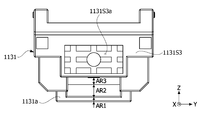
제4 홀더 외측면(1131S4)은 제4 안착홈(1131S4a)을 포함할 수 있다. 제4 안착홈(1131S4a)에는 틸팅 가이드부(1141)가 위치할 수 있다. 또한, 제4 안착홈(1131S4a)에는 제2 부재(1131a)와 제1 부재(1126)가 위치할 수 있다. 그리고 제4 안착홈(1131S4a)은 복수 개의 영역을 포함할 수 있다. 제1 영역(AR1)과 제2 영역(AR2) 그리고 제3 영역(AR3)을 포함할 수 있다. The fourth holder outer surface 1131S4 may include a fourth seating groove 1131S4a. A tilting
제1 영역(AR1)에는 제2 부재(1131a)가 위치할 수 있다. 즉, 제1 영역(AR1)은 제2 부재(1131a)와 제1 방향(X축 방향)으로 중첩될 수 있다. 특히, 제1 영역(AR1)은 제2 부재(1131a)의 부재 베이스부가 위치하는 영역일 수 있다. 이 때, 제1 영역(AR1)은 제4 홀더 외측면(1131S4) 상에 위치할 수 있다. 즉, 제1 영역(AR1)은 제4 안착홈(1131S4a)의 상부에 위치한 영역에 대응할 수 있다. 이 경우, 제1 영역(AR1)은 제4 안착홈(1131S4a) 내의 일 영역이 아닐 수도 있다.A
제2 영역(AR2)에는 제1 부재(1126)가 위치할 수 있다. 즉, 제2 영역(AR2)은 제1 부재(1126)와 제1 방향(X축 방향)으로 중첩될 수 있다. A
또한, 제2 영역(AR2)은 제1 영역과 같이 제4 홀더 외측면(1131S4) 상에 위치할 수 있다. 즉, 제2 영역(AR2)은 제4 안착홈(1131S4a)의 상부에 위치한 영역에 대응할 수 있다Also, the second area AR2 may be located on the fourth holder outer surface 1131S4 like the first area. That is, the second area AR2 may correspond to an area located above the fourth seating groove 1131S4a.
제3 영역(AR3)에는 틸팅 가이드부가 위치할 수 있다. 특히, 제3 영역(AR3)에는 틸팅 가이드부의 베이스가 위치할 수 있다. 즉, 제3 영역(AR3)은 틸팅 가이드부(예로, 베이스)와 제1 방향(X축 방향)으로 중첩될 수 있다. A tilting guide unit may be positioned in the third area AR3 . In particular, the base of the tilting guide part may be positioned in the third area AR3 . That is, the third area AR3 may overlap the tilting guide part (eg, the base) in the first direction (X-axis direction).
또한, 제2 영역(AR2)은 제1 영역(AR1)과 제3 영역(AR3) 사이에 위치할 수 있다. Also, the second area AR2 may be positioned between the first area AR1 and the third area AR3 .
그리고 제1 영역(AR1)에는 제2 부재가 배치되고, 제2 부재(1131a)는 제1 홈(gr1)을 포함할 수 있다. 실시예로, 제2 부재(1131a)는 내측면(1131aas)에 형성된 제1 홈(gr1)을 포함할 수 있다. 그리고 제1 홈(gr1)에는 상술한 바와 같이 제2 자성체가 배치될 수 있다. In addition, a second member may be disposed in the first area AR1 , and the
그리고 상술한 바와 같이 제2 영역(AR2)에는 제1 부재가 배치될 수 있다. 제1 홈(gr1)은 제2 홈(gr2)과 마주보게 위치할 수 있다. 예컨대, 제1 홈(gr1)은 제2 홈(gr2)과 제3 방향(Z축 방향)으로 적어도 일부 중첩될 수 있다.And as described above, the first member may be disposed in the second area AR2 . The first groove gr1 may be positioned to face the second groove gr2 . For example, the first groove gr1 may at least partially overlap the second groove gr2 in the third direction (Z-axis direction).
그리고 제2 자성체에서 발생한 척력이 제2 부재를 통해 홀더(1131)의 제4 안착홈(1131S4a)으로 전달될 수 있다. 이에, 홀더는 제2 자성체에서 발생한 척력과 동일한 방향으로 틸팅 가이드부로 힘을 가할 수 있다.In addition, the repulsive force generated by the second magnetic body may be transmitted to the fourth seating groove 1131S4a of the
제1 부재는 외측면에 형성된 제1 홈(gr1)과 마주하는 제2 홈(gr2)을 포함할 수 있다. 또한, 제1 부재는 상술한 바와 같이 내측면에 형성된 제2 돌기홈을 포함할 수 있다. 그리고 제2 돌기홈에는 제2 돌출부가 안착할 수 있다.The first member may include a second groove gr2 facing the first groove gr1 formed on the outer surface. In addition, the first member may include a second protrusion groove formed on the inner surface as described above. In addition, the second protrusion may be seated in the second protrusion groove.
또한, 제2 자성체와 마찬가지로, 제1 자성체와 제2 자성체에 의해 발생한 척력이 제1 부재에 가해질 수 있다. 이에 따라, 제1 부재와 제2 부재는 척력을 통해 제1 부재와 홀더(1131) 사이에 배치된 틸팅 가이드부를 가압할 수 있다.Also, like the second magnetic body, a repulsive force generated by the first magnetic body and the second magnetic body may be applied to the first member. Accordingly, the first member and the second member may press the tilting guide part disposed between the first member and the
제3 영역(AR3)에는 틸팅 가이드부(1141)가 배치될 수 있다. A tilting
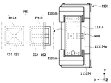
그리고 제1 돌기홈(PH1)은 제4 안착홈(1131S4a)에 위치할 수 있다. 또한, 제1 돌기홈(PH1)에는 틸팅 가이드부(1141)의 제1 돌출부가 수용될 수 있다. 이에, 제1 돌출부(PR1)는 제1 돌기홈과 접할 수 있다. 제1 돌기홈(PH1)은 최대 직경이 제1 돌출부(PR1)의 최대 직경에 대응할 수 있다. 이는 제2 돌기홈과 제2 돌출부(PR2)에도 동일하게 적용될 수 있다. 즉, 제2 돌기홈은 최대 직경이 제2 돌출부(PR2)의 최대 직경에 대응할 수 있다. 이에, 제2 돌출부는 제2 돌기홈과 접할 수 있다. 이러한 구성에 의하여, 제1 돌출부를 기준으로 제1 축 틸트와 제2 돌출부를 기준으로 제2 축 틸트가 용이하게 일어날 수 있으며, 틸트의 반경이 향상될 수 있다.In addition, the first protrusion groove PH1 may be located in the fourth seating groove 1131S4a. In addition, the first protrusion of the tilting
또한, 실시예로, 제1 돌기홈(PH1)은 복수 개일 수 있다. 예컨대, 제1 돌기홈(PH1) 및 제2 돌기홈(PH2) 중 어느 하나는 제1-1 돌기홈(PH1a)과 제1-2 돌기홈(PH1b)을 포함할 수 있다. 이하에서, 제1 돌기홈(PH1)이 제1-1 돌기홈(PH1a)과 제1-2 돌기홈(PH1b)을 포함하는 것으로 설명한다. 그리고 이하의 설명은 제2 돌기홈(PH2)에도 동일하게 적용될 수 있다. 예컨대, 제2 돌기홈(PH2)은 제2-1 돌기홈 및 제2-2 돌기홈을 포함하고, 제2-1 돌기홈은 제1-1 돌기홈의 설명이 적용되고, 제2-2 돌기홈은 제1-2 돌기홈의 설명이 적용될 수 있다.Also, in an embodiment, the number of the first protrusion grooves PH1 may be plural. For example, any one of the first protrusion groove PH1 and the second protrusion groove PH2 may include a 1-1 protrusion groove PH1a and a 1-2 protrusion groove PH1b. Hereinafter, it will be described that the first protrusion groove PH1 includes a 1-1 protrusion groove PH1a and a 1-2 protrusion groove PH1b. And the following description may be equally applied to the second protrusion groove PH2. For example, the second protrusion groove PH2 includes the 2-1 protrusion groove and the 2-2 protrusion groove, and the description of the 1-1 protrusion groove is applied to the 2-1 protrusion groove, and the 2-2 protrusion groove is applied. For the protrusion groove, the description of the 1-2 protrusion groove may be applied.
제1-1 돌기홈(PH1a)과 제1-2 돌기홈(PH1b)은 제1 방향(x축 방향)으로 나란히 배치될 수 있다. 제1-1 돌기홈(PH1a)과 제1-2 돌기홈(PH1b)은 최대 넓이가 서로 동일할 수 있다. The 1-1 protrusion groove PH1a and the 1-2 protrusion groove PH1b may be arranged side by side in the first direction (x-axis direction). The 1-1 protrusion groove PH1a and the 1-2 protrusion groove PH1b may have the same maximum width.
복수 개의 제1 돌기홈(PH1)은 경사면의 개수가 서로 상이할 수 있다. 예컨대, 제1 돌기홈(PH1)은 홈저면 및 경사면을 포함할 수 있다. 이 때, 복수 개의 돌기홈은 경사면의 개수가 서로 상이할 수 있다. 또한, 돌기 홈에서 저면의 넓이도 상이할 수 있다. The number of inclined surfaces of the plurality of first protrusion grooves PH1 may be different from each other. For example, the first protrusion groove PH1 may include a bottom surface of the groove and an inclined surface. In this case, the number of inclined surfaces of the plurality of protrusion grooves may be different from each other. Also, the width of the bottom surface of the projection groove may be different.
예컨대, 제1-1 돌기홈(PH1a)은 제1 홈저면(LS1)과 제1 경사면(CS1)을 포함할 수 있다. 제1-2 돌기홈(PH1b)은 제2 홈저면(LS2)과 제2 경사면(CS2)을 포함할 수 있다.For example, the 1-1 protrusion groove PH1a may include a first groove bottom surface LS1 and a first inclined surface CS1. The 1-2 protrusion groove PH1b may include a second groove bottom surface LS2 and a second inclined surface CS2.
이 때, 제1 홈저면(LS1)과 제2 홈저면(LS2)은 넓이가 서로 상이할 수 있다. 제1 홈저면(LS1)의 넓이는 제2 홈저면(LS2)의 넓이보다 작을 수 있다. In this case, the first groove bottom surface LS1 and the second groove bottom surface LS2 may have different widths. An area of the first groove bottom surface LS1 may be smaller than an area of the second groove bottom surface LS2.
또한, 제1 홈저면(LS1)과 접하는 제1 경사면(CS1)의 개수는 제2 경사면(CS2)의 개수와 상이할 수 있다. 예컨대, 제1 경사면(CS1)의 개수는 제2 경사면(CS2)의 개수보다 클 수 있다. Also, the number of the first inclined surfaces CS1 in contact with the first groove bottom surface LS1 may be different from the number of the second inclined surfaces CS2 . For example, the number of the first inclined surfaces CS1 may be greater than the number of the second inclined surfaces CS2 .
이러한 구성에 의하여, 제1 돌기홈(PH1)에 안착하는 제1 돌출부의 조립 공차를 용이하게 보완할 수 있다. 예컨대, 제1 경사면(CS1)의 개수가 제2 경사면(CS2)의 개수보다 많으므로 제1 돌출부가 보다 많은 경사면과 접하여, 제1-1 돌기홈(PH1a)에서 제1 돌출부의 위치를 보다 정확하게 유지할 수 있다. With this configuration, the assembly tolerance of the first protrusion seated in the first protrusion groove PH1 can be easily supplemented. For example, since the number of the first inclined surfaces CS1 is greater than the number of the second inclined surfaces CS2, the first protrusions come into contact with the more inclined surfaces, so that the position of the first protrusions in the 1-1 protrusion groove PH1a is more accurately determined. can keep
이와 달리, 제1-2 돌기홈(PH1b)에서는 제1 돌출부와 접하는 경사면의 개수가 제1-1 돌기홈(PH1b) 대비 작은 바, 제1 돌출부의 위츠 조정이 수월하게 이루어질 수 있다.On the other hand, in the 1-2 protrusion groove PH1b, the number of inclined surfaces in contact with the first protrusion is smaller than that of the 1-1 protrusion groove PH1b, so that the positions of the first protrusion can be easily adjusted.
실시예로, 제2 경사면(CS2)은 제2 방향(Y축 방향)으로 서로 이격 배치될 수 있다. 그리고 제2 홈저면(LS2)은 제1 방향(X축 방향)으로 연장되어 제1 돌출부가 제2 경사면(CS2)과 접한 상태에서 제1 방향(X축 방향)으로 용이하게 이동할 수 있다. 즉, 제1-2 돌기홈(PH1b)에서는 제1 돌출부가 용이하게 위치 조정될 수 있다.In an embodiment, the second inclined surfaces CS2 may be spaced apart from each other in the second direction (Y-axis direction). In addition, the second groove bottom surface LS2 extends in the first direction (X-axis direction) so that the first protrusion can easily move in the first direction (X-axis direction) while the first protrusion is in contact with the second inclined surface CS2 . That is, the position of the first protrusion may be easily adjusted in the 1-2 protrusion groove PH1b.
또한, 본 실시예에서, 제1 영역(AR1), 제2 영역(AR2) 및 제3 영역(AR3)은 제1 방향(X축 방향)으로 높이가 상이할 수 있다. 실시예로, 제1 영역(AR1)은 제2 영역(AR2) 및 제3 영역(AR3)보다 제1 방향(X축 방향)으로 높이가 더 클 수 있다. 이에, 제1 영역(AR1)과 제2 영역(AR2) 사이에 단차가 위치할 수 있다Also, in the present exemplary embodiment, the first area AR1 , the second area AR2 , and the third area AR3 may have different heights in the first direction (X-axis direction). In an embodiment, the first area AR1 may have a greater height in the first direction (X-axis direction) than the second area AR2 and the third area AR3 . Accordingly, a step may be positioned between the first area AR1 and the second area AR2 .
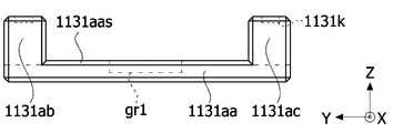
또한, 제2 부재(1131a)는 제1 홈(gr1)을 포함할 수 있다. 다시 말해, 부재 베이스부(1131aa)의 내측면에는 제1 홈(gr1)이 위치할 수 있다. 그리고 제1 홈(gr1)에는 상술한 제2 자성체가 안착할 수 있다. 또한, 제1 홈(gr1)은 제2 자성체의 개수에 따라 복수 개일 수 있다. 즉, 제1 홈(gr1)은 제2 자성체의 개수에 대응한 개수로 이루어질 수 있다.Also, the
또한, 제2 부재(1131a)는 부재 베이스부(1131aa), 제1 연장부(1131ab) 및 제2 연장부(1131ac)를 포함할 수 있다.In addition, the
부재 베이스부(1131aa)는 제1 카메라 엑추에이터의 최외측에 위치할 수 있다. 부재 베이스부(1131aa)는 제1 부재의 외측에 위치할 수 있다. 즉, 제1 부재는 부재 베이스부(1131aa)와 틸팅 가이드부 사이에 위치할 수 있다.The member base portion 1131aa may be located at the outermost side of the first camera actuator. The member base portion 1131aa may be positioned outside the first member. That is, the first member may be positioned between the member base part 1131aa and the tilting guide part.
제1 연장부(1131ab)는 부재 베이스부(1131aa)의 가장자리에서 제3 방향(Z축 방향)으로 연장될 수 있다. 즉, 제1 연장부(1131ab)는 부재 베이스부(1131aa)에서 홀더(1131)를 향해 연장될 수 있다. 이는 제2 연장부(1131ac)도 마찬가지이다. 또한, 제2 연장부(1131ac)는 부재 베이스부(1131aa)의 가장자리에서 제3 방향(Z축 방향)을 연장될 수 있다. 실시예로, 제1 연장부(1131ab)와 제2 연장부(1131ac)는 부재 베이스부(1131aa)의 제2 방향(Y축 방향)으로 가장자리에 위치할 수 있다. 그리고 제1 연장부(1131ab)와 제2 연장부(1131ac)는 상부부재와 하부부재 사이에 배치될 수 있다.The first extension portion 1131ab may extend in the third direction (Z-axis direction) from the edge of the member base portion 1131aa. That is, the first extension portion 1131ab may extend from the member base portion 1131aa toward the
이에, 제2 부재(1131a)는 제1 연장부(1131ab)와 제2 연장부(1131ac)에 의해 형성된 그루브(groove)를 가질 수 있다. 즉, 그루브(groove)는 제1 연장부(1131ab)와 제2 연장부(1131ac) 사이에 위치할 수 있다. 이에, 제1 연장부(1131ab)와 제2 연장부(1131ac)는 부재 베이스부(1131aa)에 의해서만 서로 연결될 수 있다. 이러한 구성에 의하여, 제2 부재(1131a)는 부재 베이스부(1131aa)의 중앙 특히, 제1 홈(gr1)에 안착한 제2 자성체에 의한 척력을 지속적으로 받을 수 있다. Accordingly, the
그리고 제2 부재(1131a)는 홀더와 결합하여 X축 틸트 및 Y축 틸트 시 이동하는 바, 제2 부재(1131a)의 강성이 제1 부재의 강성보다 더 클 수 있다. In addition, since the
나아가, 상술한 바와 같이 실시예에 따른 제1 부재는 상부부재와 하부부재를 가짐으로써 강성이 증가할 수 있다. 이러한 구성에 의하여, 제2 부재와 제1 부재 간의 강성 차이가 줄어들 수 있다. 이로써, 제2 부재(1131a)와 제2 부재(1131a)에 결합된 홀더(1131)가 함께 X축 틸트 또는 Y축 틸트되는 경우, 제2 부재(1131a)는 제1 부재와의 인접거리가 작아지고, 제1 부재와 접촉할 수 있다. 이에, 제1 부재가 상술한 바와 같이 향상된 강성을 가짐으로써 스토퍼로서 동작을 용이하게 수행할 수 있다. 즉, 카메라 엑추에이터의 신뢰성이 개선될 수 있다.Furthermore, as described above, the rigidity of the first member according to the embodiment may be increased by having the upper member and the lower member. With this configuration, a difference in stiffness between the second member and the first member may be reduced. Accordingly, when the
나아가, 제1 부재와 제2 부재 간의 강성 차이가 감소하여 틸트 시 접촉에 의한 데미지가 최소화될 수 있다. 즉, 카메라 엑추에이터의 신뢰성이 향상될 수 있다.Furthermore, since the difference in stiffness between the first member and the second member is reduced, damage due to contact during tilting may be minimized. That is, the reliability of the camera actuator may be improved.
또한, 제1 연장부(1131ab)는 제2 연장부(1131ac)와 제2 방향(Y축 방향)으로 이격되어 이격 공간을 형성할 수 있다. 이러한 이격 공간에는 제1 부재와 틸팅 가이드부가 안착할 수 있다. 또한, 이격 공간에는 제2 자성체와 제1 자성체가 위치할 수 있다.In addition, the first extension portion 1131ab may be spaced apart from the second extension portion 1131ac in the second direction (Y-axis direction) to form a separation space. The first member and the tilting guide unit may be seated in this spaced apart space. In addition, the second magnetic body and the first magnetic body may be positioned in the separation space.
또한, 제1 연장부(1131ab)와 제2 연장부(1131ac)는 제3 방향(Z축 방향)으로 길이가 동일할 수 있다. 이에, 결합력 및 무게 등이 균형있게 형성되어 홀더의 틸트가 일측으로 기울어지지 않고 정확하게 이루어질 수 있다.Also, the first extension 1131ab and the second extension 1131ac may have the same length in the third direction (Z-axis direction). Accordingly, since the coupling force and weight are balanced, the tilt of the holder can be accurately performed without inclining to one side.
그리고 제1 연장부(1131ab)와 제2 연장부(1131ac)는 홀더와 결합할 수 있다. 본 명세서에서 결합은 상술한 돌기 및 홈 구조 이외에 접합 부재를 통해 서로 결합될 수 있음을 이해해야 한다. 실시예로, 제1 연장부(1131ab)와 제2 연장부(1131ac)는 제3 방향(Z축 방향)으로 형성된 제3 결합홈(1131k)을 포함할 수 있다. 또한, 제4 안착홈(1131S4a)에서 제1 연장부(1131ab)와 제2 연장부(1131ac)와 제3 방향(Z축 방향)으로 중첩되는 영역에는 결합 돌기(1131m)가 위치할 수 있다. 결합 돌기(1131m)는 제3 결합홈(1131k)과 대응하여 위치할 수 있다. In addition, the first extension portion 1131ab and the second extension portion 1131ac may be coupled to the holder. In this specification, it should be understood that the coupling may be coupled to each other through a bonding member other than the above-described protrusion and groove structures. In an embodiment, the first extension portion 1131ab and the second extension portion 1131ac may include a
예컨대, 제3 결합홈(1131k)에는 에폭시 등의 접합 부재가 도포될 수 있다. 그리고 결합 돌기(1131m)는 제1 연장부(1131ab)와 제2 연장부(1131ac)의 제3 결합홈(1131k)으로 삽입될 수 있다. 이러한 구성에 의하여, 제2 부재(1131a)와 홀더(1131)가 서로 결합할 수 있다. 또한, 이러한 결합으로 제2 부재(1131a)에 가해지는 척력이 홀더(1130)으로 전달될 수 있다.For example, a bonding member such as epoxy may be applied to the
다만, 상술한 바와 같이 돌기 및 홈 구조는 서로 위치가 바뀔 수도 있음을 이해해야 한다.However, it should be understood that the positions of the protrusion and the groove structure may be changed from each other as described above.
도 9a는 실시예에 따른 제1 카메라 엑추에이터의 틸팅 가이드부의 사시도이고, 도 9b는 도 9a와 상이한 방향의 사시도이고, 도 9c는 도 9a에서 FF’로 바라본 단면도이다.9A is a perspective view of a tilting guide part of a first camera actuator according to an embodiment, FIG. 9B is a perspective view in a different direction from FIG. 9A, and FIG. 9C is a cross-sectional view taken along FF′ in FIG. 9A.
실시예에 따른 틸팅 가이드부(1141)는 베이스(BS), 베이스(BS)의 제1 면(1141a)으로부터 돌출되는 제1 돌출부(PR1), 베이스(BS)의 제2 면(1141b)으로부터 돌출되는 제2 돌출부(PR2)를 포함할 수 있다. 또한, 구조에 따라 제1 돌출부와 제2 돌출부는 형성된 면이 반대일 수 있으나, 도면을 기준으로 이하 설명한다. 또한, 제1 돌출부(PR1)와 제2 돌출부(PR2)는 베이스(BS)와 일체로 형성될 수 있으며, 도면과 같이 제1 돌출부(PR1)와 제2 돌출부(RP2)는 볼과 같이 구 형상을 가질 수 있음을 이해해야 한다. The tilting
먼저, 베이스(BS)는 제1 면(1141a) 및 제1 면(1141a)에 대향하는 제2 면(1141b)을 포함할 수 있다. 즉, 제1 면(1141a)은 제2 면(1141b)과 제3 방향(Z축 방향)으로 이격될 수 있고, 틸팅 가이드부(1141) 내에서 서로 대향하는 또는 서로 마주보는 외측면일 수 있다. First, the base BS may include a
틸팅 가이드부(1141)는 제1 면(1141a) 상에서 일측으로 연장된 제1 돌출부(PR1)를 포함할 수 있다. 실시예에 따르면, 제1 돌출부(PR1)는 제1 면(1141a)에서 홀더를 향해 돌출될 수 있다. 제1 돌출부(PR1)는 복수 개로, 제1-1 돌출부(PR1a)와 제1-2 돌출부(PR1b)를 포함할 수 있다. The tilting
제1-1 돌출부(PR1a)와 제1-2 돌출부(PR1b)는 제1 방향(X축 방향)으로 나란히 위치할 수 있다. 다시 말해, 제1-1 돌출부(PR1a)와 제1-2 돌출부(PR1b)는 제1 방향(X축 방향)으로 중첩될 수 있다. 또한, 실시예에서 제1-1 돌출부(PR1a)와 제1-2 돌출부(PR1b)는 제1 방향(X축 방향)으로 연장된 가상선에 의해 이등분될 수 있다.The 1-1 protrusion PR1a and the 1-2 protrusion PR1b may be positioned side by side in the first direction (X-axis direction). In other words, the 1-1 protrusion PR1a and the 1-2 protrusion PR1b may overlap in the first direction (X-axis direction). Also, in the embodiment, the 1-1 protrusion PR1a and the 1-2 protrusion PR1b may be bisected by an imaginary line extending in the first direction (X-axis direction).
또한, 제1-1 돌출부(PR1a)와 제1-2 돌출부(PR1b)는 곡률을 가지며, 예를 들어 반구 형상일 수 있다. 그리고 제1-1 돌출부(PR1a)와 제1-2 돌출부(PR1b)는 베이스(BS)의 제1 면(1141a)로부터 가장 이격된 지점에서 하우징의 제1 홈과 접할 수 있다. In addition, the 1-1 protrusion PR1a and the 1-2 protrusion PR1b may have a curvature and, for example, may have a hemispherical shape. In addition, the 1-1 protrusion PR1a and the 1-2 protrusion PR1b may contact the first groove of the housing at a point most spaced apart from the
또한, 제1 면(1141a)에는 얼라인 홈(1141aa)이 위치할 수 있다. 얼라인 홈(1141aa)은 제1 면(1141a)에서 일측에 배치되어, 조립 공정시 틸팅 가이드부(1141)의 조립 위치 또는 조립 방향을 제공할 수 있다.Also, an alignment groove 1141aa may be positioned on the
또한, 틸팅 가이드부(1141)는 제2 면(1141a) 상에서 일측으로 연장된 제2 돌출부(PR2)를 포함할 수 있다. 실시예에 따르면, 제2 돌출부(PR2)는 제2 면(1141b)에서 하우징을 향해 돌출될 수 있다. 그리고 제2 돌출부(PR2)는 복수 개이며, 실시예에서 제2-1 돌출부(PR2a)와 제2-2 돌출부(PR2b)를 포함할 수 있다.Also, the tilting
제2-1 돌출부(PR2a)와 제2-2 돌출부(PR2b)는 제2 방향(Y축 방향)으로 나란히 위치할 수 있다. 즉, 제2-1 돌출부(PR2a)와 제2-2 돌출부(PR2b)는 제2 방향(Y축 방향)으로 중첩될 수 있다. 또한, 실시예에서 제2-1 돌출부(PR2a)와 제2-2 돌출부(PR2b)는 제2 방향(Y축 방향)으로 연장된 가상선에 의해 이등분될 수 있다.The 2-1 protrusion PR2a and the 2-2 protrusion PR2b may be positioned side by side in the second direction (Y-axis direction). That is, the 2-1 protrusion PR2a and the 2-2 protrusion PR2b may overlap in the second direction (Y-axis direction). Also, in the exemplary embodiment, the 2-1 th protrusion PR2a and the 2-2 th protrusion PR2b may be bisected by an imaginary line extending in the second direction (Y-axis direction).
제2-1 돌출부(PR2a)와 제2-2 돌출부(PR2b)는 곡률을 가질 수 있으며, 예를 들어 반구 형상일 수 있다. 그리고 제2-1 돌출부(PR2a)와 제2-2 돌출부(PR2b)는 베이스(BS)의 제2 면(1141b)로부터 이격된 지점에서 제2 부재(1131a)와 접할 수 있다.The second-first protrusion PR2a and the second-second protrusion PR2b may have a curvature, for example, a hemispherical shape. In addition, the second-first protrusion PR2a and the second-second protrusion PR2b may contact the
제1-1 돌출부(PR1a)와 제1-2 돌출부(PR1b)는 제2 방향으로 제2-1 돌출부(PR2a)와 제2-2 돌출부(PR2b) 사이 영역에 위치할 수 있다. 실시예에 따르면, 제2 방향으로 제2-1 돌출부(PR2a)와 제2-2 돌출부(PR2b) 간의 이격 공간의 중앙에 제1-1 돌출부(PR1a)와 제1-2 돌출부(PR1b)가 위치할 수 있다. 이러한 구성에 의하여, 실시예에 따른 엑추에이터는 X축을 기준으로 X축 틸트의 각도가 동일 범위를 가지게 할 수 있다. 다시 말해, 틸팅 가이드부(1141)는 제1-1 돌출부(PR1a)와 제1-2 돌출부(PR1b)를 기준으로 홀더가 X축 틸트가 가능한 범위(예컨대, 양/음의 범위)를 X축을 기준으로 동일하게 제공할 수 있다.The 1-1 protrusion PR1a and the 1-2 protrusion PR1b may be positioned in a region between the 2-1 protrusion PR2a and the 2-2 protrusion PR2b in the second direction. According to the embodiment, the 1-1 protrusion PR1a and the 1-2 protrusion PR1b are disposed in the center of the space between the 2-1 protrusion PR2a and the 2-2 protrusion PR2b in the second direction. can be located With this configuration, the actuator according to the embodiment may have the X-axis tilt angle with respect to the X-axis in the same range. In other words, the tilting
또한, 제2-1 돌출부(PR2a)와 제2-2 돌출부(PR2b)는 제1 방향으로 제1-1 돌출부(PR1a)와 제1-2 돌출부(PR1b) 사이 영역에 위치할 수 있다. 실시예에 따르면, 제1 방향으로 제1-1 돌출부(PR1a)와 제1-2 돌출부(PR1b) 간의 이격 공간의 중앙에 제2-1 돌출부(PR2a)와 제2-2 돌출부(PR2b)가 위치할 수 있다. 이러한 구성에 의하여, 실시예에 따른 엑추에이터는 Y축을 기준으로 Y축 틸트의 각도가 동일 범위를 가지게 할 수 있다. 다시 말해, 제2-1 돌출부(PR2a)와 제2-2 돌출부(PR2b)를 기준으로 틸팅 가이드부(1141) 및 홀더는 Y축 틸트가 가능한 범위(예컨대, 양/음의 범위)를 Y축을 기준으로 동일하게 제공할 수 있다.Also, the 2-1 protrusion PR2a and the 2-2 protrusion PR2b may be positioned in a region between the 1-1 protrusion PR1a and the 1-2 protrusion PR1b in the first direction. According to the embodiment, the 2-1 protrusion PR2a and the 2-2 protrusion PR2b are disposed at the center of the space between the 1-1 protrusion PR1a and the 1-2 protrusion PR1b in the first direction. can be located With this configuration, the actuator according to the embodiment can have the angle of the Y-axis tilt with respect to the Y-axis in the same range. In other words, the tilting
구체적으로, 제1 면(1141a)은 제1 외측선(M1), 제2 외측선(M2), 제3 외측선(M3) 및 제4 외측선(M4)을 포함할 수 있다. 제1 외측선(M1)과 제2 외측선(M2)은 서로 마주보고, 제3 외측선(M3)과 제4 외측선(M4)은 서로 마주볼 수 있다. 그리고 제1 외측선(M1)과 제2 외측선(M2) 사이에 제3 외측선(M3) 및 제4 외측선(M4)이 위치할 수 있다. 그리고 제1 외측선(M1)과 제2 외측선(M2)은 제1 방향(X축 방향)과 수직하나, 제3 외측선(M3)과 제4 외측선(M4)은 제1 방향(X축 방향)과 평행할 수 있다. Specifically, the
이 때, 제1 돌출부(PR1)는 제1 가상선(VL1) 상에 위치할 수 있다. 여기서, 제1 가상선(LV1)은 제1 외측선(M1)과 제2 외측선(M2)을 이등분하는 선이다. 또는 제1,3 가상선(LV1, LV1')은 베이스(BS)를 제2 방향(Y축 방향)으로 이등분하는 선이다. 이에 따라, 제1 돌출부(PR1)를 통해 틸팅 가이드부(1141)가 X축 틸트를 용이하게 수행할 수 있다. 뿐만 아니라, 틸팅 가이드부(1141)가 X축 틸트를 제1 가상선(VL1)을 기준으로 수행하므로 회전력이 틸팅 가이드부(1141)에 균일하게 가해질 수 있다. 이에, X축 틸트가 정교하게 이루어지고 소자의 신뢰성이 개선될 수 있다. In this case, the first protrusion PR1 may be positioned on the first virtual line VL1 . Here, the first virtual line LV1 is a line that bisects the first outer line M1 and the second outer line M2 . Alternatively, the first and third virtual lines LV1 and LV1' are lines that bisect the base BS in the second direction (Y-axis direction). Accordingly, the tilting
또한, 제1-1 돌출부(PR1a)와 제1-2 돌출부(PR1b)는 제1 가상선(VL1) 및 제2 가상선(VL2)을 기준으로 대칭으로 배치될 수 있다. 또는 제1-1 돌출부(PR1a)와 제1-2 돌출부(PR1b)는 제1 중심점(C1)을 기준으로 대칭으로 위치할 수 있다. 이러한 구성에 의하여, X축 틸트 시 제1 돌출부(PR1)에 의해 지지되는 지지력이 제2 가상선(VL2)을 기준으로 상측과 하측에 동일하게 가해질 수 있다. 이에, 틸팅 가이드부의 신뢰성이 개선될 수 있다. 여기서, 제2 가상선(VL2)은 제3 외측선(M3)과 제4 외측선(M4)을 이등분하는 선이다. 또는 제2,4 가상선(LV2, LV2')은 베이스(BS)를 제1 방향(X축 방향)으로 이등분하는 선이다.Also, the 1-1 protrusion PR1a and the 1-2 protrusion PR1b may be symmetrically disposed with respect to the first imaginary line VL1 and the second imaginary line VL2 . Alternatively, the 1-1 protrusion PR1a and the 1-2 protrusion PR1b may be symmetrically positioned with respect to the first central point C1 . With this configuration, the support force supported by the first protrusion PR1 may be equally applied to the upper and lower sides of the second virtual line VL2 when tilting the X-axis. Accordingly, the reliability of the tilting guide unit may be improved. Here, the second virtual line VL2 is a line that bisects the third outer line M3 and the fourth outer line M4 . Alternatively, the second and fourth virtual lines LV2 and LV2' are lines that bisect the base BS in the first direction (X-axis direction).
그리고 제1 중심점(C1)은 제1 가상선(VL1)과 제2 가상선(VL2)의 교점일 수 있다. 또는, 틸팅 가이드부(1141)의 형상에 따라 무게 중심에 대응하는 지점일 수도 있다. In addition, the first central point C1 may be an intersection of the first virtual line VL1 and the second virtual line VL2 . Alternatively, it may be a point corresponding to the center of gravity according to the shape of the tilting
또한, 제2 면(1141b)은 제5 외측선(M1’), 제6 외측선(M2’), 제7 외측선(M3’) 및 제8 외측선(M4’)을 포함할 수 있다. 제5 외측선(M1’)과 제6 외측선(M2’)은 서로 마주보고, 제7 외측선(M3’)과 제8 외측선(M4’)은 서로 마주볼 수 있다. 그리고 제5 외측선(M1’)과 제6 외측선(M2’) 사이에 제7 외측선(M3’) 및 제8 외측선(M4’)이 위치할 수 있다. 그리고 제5 외측선(M1’)과 제6 외측선(M2’)은 제1 방향(X축 방향)과 수직하나, 제7 외측선(M3’)과 제8 외측선(M4’)은 제1 방향(X축 방향)과 평행할 수 있다.In addition, the
뿐만 아니라, 틸팅 가이드부(1141)가 Y축 틸트를 제4 가상선(VL2’)을 기준으로 수행하므로 회전력이 틸팅 가이드부(1141)에 균일하게 가해질 수 있다. 이에, Y축 틸트가 정교하게 이루어지고 소자의 신뢰성이 개선될 수 있다. In addition, since the tilting
또한, 제2-1 돌출부(PR2a)와 제2-2 돌출부(PR2b)는 제4 가상선(VL2’) 상에 서 제3 가상선(VL1’)에 대칭으로 배치될 수 있다. 또는 제2-1 돌출부(PR2a)와 제2-2 돌출부(PR2b)는 제2 중심점(C1’)을 기준으로 대칭으로 위치할 수 있다. 이러한 구성에 의하여, Y축 틸트 시 제2 돌출부(PR2)에 의해 지지되는 지지력이 제4 가상선(VL2’)을 기준으로 틸팅 가이드부의 상측과 하측에 동일하게 가해질 수 있다. 이에, 틸팅 가이드부의 신뢰성이 개선될 수 있다. 여기서, 제3 가상선(LV1’)은 제5 외측선(M1’)과 제6 외측선(M2’)을 이등분하는 선이다. 그리고 제2 중심점(C1’)은 제3 가상선(VL1’)과 제4 가상선(VL2’)의 교점일 수 있다. 또는, 틸팅 가이드부(1141)의 형상에 따라 무게 중심에 대응하는 지점일 수도 있다.Also, the 2-1 protrusion PR2a and the 2-2 protrusion PR2b may be symmetrically disposed on the fourth imaginary line VL2 ′ to the third imaginary line VL1 ′. Alternatively, the second-first protrusion PR2a and the second-second protrusion PR2b may be symmetrically positioned with respect to the second central point C1 ′. According to this configuration, the supporting force supported by the second protrusion PR2 may be equally applied to the upper and lower sides of the tilting guide unit with respect to the fourth virtual line VL2 ′ when the Y-axis is tilted. Accordingly, the reliability of the tilting guide unit may be improved. Here, the third virtual line LV1' is a line that bisects the fifth outer line M1' and the sixth outer line M2'. In addition, the second central point C1' may be an intersection of the third virtual line VL1' and the fourth virtual line VL2'. Alternatively, it may be a point corresponding to the center of gravity according to the shape of the tilting
또한, 제1-1 돌출부(PR1a)와 제1-2 돌출부(PR1b) 사이의 제1 방향(X축 방향)으로 간격(DR2)은 제2 돌출부(PR2)의 제1 방향(X축 방향)으로 길이보다 클 수 있다. 이에, 제1-1 돌출부(PR1a) 및 제1-2 돌출부(PR1b)를 기준으로 X축 틸트 수행 시, 제2 돌출부(PR2)에 의한 저항을 최소화할 수 있다.In addition, the interval DR2 in the first direction (X-axis direction) between the 1-1 protrusion PR1a and the 1-2 protrusion PR1b is in the first direction (X-axis direction) of the second protrusion PR2 . can be greater than the length. Accordingly, when the X-axis tilt is performed based on the 1-1 protrusion PR1a and the 1-2 protrusion PR1b, resistance due to the second protrusion PR2 may be minimized.
이와 대응하여, 제2-1 돌출부(PR2a)와 제2-2 돌출부(PR2b) 사이의 제2 방향(Y축 방향)으로 간격(ML2)은 제1 돌출부(PR1)의 제2 방향(Y축 방향)으로 길이보다 클 수 있다. 이에, 제2-1 돌출부(PR2a) 및 제2-2 돌출부(PR2b)를 기준으로 Y축 틸트 수행 시, 제1 돌출부(PR1)에 의한 저항을 최소화할 수 있다.Correspondingly, the interval ML2 in the second direction (Y-axis direction) between the 2-1 protrusion PR2a and the 2-2 protrusion PR2b is in the second direction (Y-axis) of the first protrusion PR1 . direction) may be greater than the length. Accordingly, when the Y-axis tilt is performed based on the 2-1 protrusion PR2a and the 2-2 protrusion PR2b, resistance due to the first protrusion PR1 may be minimized.
도 10은 실시예에 따른 제1 카메라 엑추에이터의 제1 구동부를 도시한 도면이다.10 is a diagram illustrating a first driving unit of a first camera actuator according to an embodiment.
도 10을 참조하면, 제1 구동부(1150)는 구동 마그넷(1151), 구동 코일(1152), 홀 센서부(1153), 제1 기판부(1154) 및 요크부(1155)를 포함한다. Referring to FIG. 10 , the
또한, 상술한 바와 같이 구동 마그넷(1151)은 전자기력에 의한 구동력을 제공하는 제1 마그넷(1151a), 제2 마그넷(1151b) 및 제3 마그넷(1151c)을 포함할 수 있다. 제1 마그넷(1151a), 제2 마그넷(1151b) 및 제3 마그넷(1151c)은 각각 홀더(1131)의 외측면에 위치할 수 있다. Also, as described above, the
또한, 구동 코일(1152)은 복수 개의 코일을 포함할 수 있다. 실시예로, 구동 코일(1152)은 제1 코일(1152a), 제2 코일(1152b) 및 제3 코일(1152c)을 포함할 수 있다. Also, the driving
제1 코일(1152a)은 제1 마그넷(1151a)과 대향하게 위치할 수 있다. 이에, 제1 코일(1152a)은 상술한 바와 같이 제1 하우징 측부(1121)의 제1 하우징 홀(1121a)에 위치할 수 있다. 또한, 제2 코일(1152b)은 제2 마그넷(1151b)과 대향하게 위치할 수 있다. 이에, 제2 코일(1152b)은 상술한 바와 같이 제2 하우징 측부(1122)의 제2 하우징 홀(1122a)에 위치할 수 있다. The
실시예에 따른 제2 카메라 엑추에이터는 구동 마그넷(1151)과 구동 코일(1152) 간의 전자기력에 의해 무버(1130)를 제1 축(X축 방향) 또는 제2 축(Y축 방향)으로 회전 제어함으로써 OIS 구현 시 디센터(decent)나 틸트(tilt) 현상의 발생을 최소화하여 최상의 광학적 특성을 제공할 수 있다. The second camera actuator according to the embodiment rotates the
또한, 실시예에 의하면 제1 하우징(1120)과 무버(1130) 사이에 배치되는 회전부(1140)의 틸팅 가이드부(1141)를 통해, OIS 구현함으로써 엑추에이터의 사이즈 제한을 해소하여 초슬림, 초소형의 카메라 엑추에이터 및 이를 포함하는 카메라 모듈을 제공할 수 있다. In addition, according to the embodiment, through the tilting
제1 기판부(1154)는 제1 기판 측부(1154a), 제2 기판 측부(1154b) 및 제3 기판 측부(1154c)를 포함할 수 있다. The
제1 기판 측부(1154a)와 제2 기판 측부(1154b)는 서로 마주보게 배치될 수 있다. 그리고 제3 기판 측부(1154c)는 제1 기판 측부(1154a)와 제2 기판 측부(1154b) 사이에 위치할 수 있다. The first
또한, 제1 기판 측부(1154a)는 제1 하우징 측부와 쉴드 캔 사이에 위치할 수 있고, 제2 기판 측부(1154b)는 제2 하우징 측부와 쉴드 캔 사이에 위치할 수 있다. 또한, 제3 기판 측부(1154c)는 제3 하우징 측부와 쉴드 캔 사이에 위치할 수 있고, 제1 기판부(1154)의 저면일 수 있다. Also, the
제1 기판 측부(1154a)는 제1 코일(1152a)과 결합하고, 전기적으로 연결될 수 있다. 또한, 제1 기판 측부(1154a)는 제1 홀 센서(1153a)와 결합하고, 전기적으로 연결될 수 있다. The first
제2 기판 측부(1154b)는 제2 코일(1152b)과 결합하고 전기적으로 연결될 수 있다. 또한, 제2 기판 측부(1154b)는 제1 홀 센서와 결합하고 전기적으로 연결될 수도 있음을 이해해야 한다. The
제3 기판 측부(1154c)는 제3 코일(1152c)과 결합하고 전기적으로 연결될 수 있다. 또한, 제3 기판 측부(1154c)는 제2 홀 센서(1153b)와 결합하고 전기적으로 연결될 수 있다. The
요크부(1155)는 제1 요크(1155a), 제2 요크(1155b) 및 제3 요크(1155c)를 포함할 수 있다. 제1 요크(1155a)는 제1 안착홈 내에 위치하고, 제1 마그넷(1151a)과 결합할 수 있다. 또한, 제2 요크(1155b)는 제2 안착홈 내에 위치하고 제2 마그넷(1151b)과 결합할 수 있다. 또한, 제3 요크(1155c)는 제3 안착홈 내에 위치하고, 제3 마그넷(1151c)과 결합할 수 있다. 이러한 제1 요크 내지 제3 요크(1155a 내지 1155c)는 제1 마그넷 내지 제3 마그넷(1151a 내지 1151c)이 제1 내지 제3 안착홈에 용이하게 안착하여 하우징과 결합하게 한다.The
도 11a는 실시예에 따른 제1 카메라 엑추에이터의 사시도이고, 도 11b는 도 11a에서 PP’로 바라본 단면도이고, 도 11c는 도 11a에서 QQ’로 바라본 단면도이다.11A is a perspective view of a first camera actuator according to an embodiment, FIG. 11B is a cross-sectional view taken along line PP′ in FIG. 11A, and FIG. 11C is a cross-sectional view taken along QQ′ in FIG. 11A.
도 11a 내지 도 11c를 참조하면, 제1 코일(1152a)은 제1 하우징 측부(1121)에 위치하고, 제1 마그넷(1151a)은 홀더(1131)의 제1 홀더 외측면(1131S1)에 위치할 수 있다. 이에, 제1 코일(1152a)과 제1 마그넷(1151a)은 서로 대향하여 위치할 수 있다. 제1 마그넷(1151a)은 제1 코일(1152a)과 제2 방향(Y축 방향)으로 적어도 일부 중첩될 수 있다.11A to 11C , the
또한, 제2 코일(1152b)은 제2 하우징 측부(1122)에 위치하고, 제2 마그넷(1151b)은 홀더(1131)의 제2 홀더 외측면(1131S2)에 위치할 수 있다. 이에, 제2 코일(1152b)과 제2 마그넷(1151b)은 서로 대향하여 위치할 수 있다. 제2 마그넷(1151b)은 제2 코일(1152b)과 제2 방향(Y축 방향)으로 적어도 일부 중첩될 수 있다. In addition, the
또한, 제1 코일(1151a)과 제2 코일(1152b)은 제2 방향(Y축 방향)으로 중첩되고, 제1 마그넷(1151a)과 제2 마그넷(1151b)은 제2 방향(Y축 방향)으로 중첩될 수 있다. In addition, the
이러한 구성에 의하여, 홀더의 외측면(제1 홀더 외측면 및 제2 홀더 외측면)에 가해지는 전자기력이 제2 방향(Y축 방향)으로 평행 축 상에 위치하여 X축 틸트가 정확하고 정밀하게 수행될 수 있다. With this configuration, the electromagnetic force applied to the outer surface of the holder (the first holder outer surface and the second holder outer surface) is located on the parallel axis in the second direction (Y-axis direction), so that the X-axis tilt is accurate and precise. can be performed.
또한, 틸팅 가이드부(1141)의 제2 돌출부(PR2a, PR2b)는 제1 하우징(1120)의 제1 부재(1126)와 접할 수 있다. 제2 돌출부(PR2)는 제1 부재(1126)의 일측면에 형성된 제2 돌기홈(PH2) 내에 안착할 수 있다. 그리고 X축 틸트를 수행하는 경우, 제2 돌출부(PR2a, PR2b)가 틸트의 기준축(또는 회전축)일 수 있다. 이에, 틸팅 가이드부(1141), 무버(1130)가 제2 방향을 따라 이동할 수 있다. In addition, the second protrusions PR2a and PR2b of the tilting
또한, 제1 홀 센서(1153a)는 상술한 바와 같이 제1 기판부(1154)와 전기적 연결 및 결합을 위해 외측에 위치할 수 있다. 다만, 이러한 위치에 한정되는 것은 아니다. Also, as described above, the
또한, 제3 코일(1151c)은 제3 하우징 측부(1123)에 위치하고, 제3 마그넷(1152c)은 홀더(1131)의 제3 홀더 외측면(1131S3)에 위치할 수 있다. 제3 코일(1151c)과 제3 마그넷(1152c)은 제1 방향(X축 방향)으로 적어도 일부 중첩될 수 있다. 이에 따라, 제3 코일(1151c)과 제3 마그넷(1152c) 간의 전자기력의 세기가 용이하게 제어될 수 있다. Also, the
틸팅 가이드부(1141)는 상술한 바와 같이 홀더(1131)의 제4 홀더 외측면(1131S4) 상에 위치할 수 있다. 또한, 틸팅 가이드부(1141)는 제4 홀더 외측면의 제4 안착홈(1131S4a) 내에 안착할 수 있다. 상술한 바와 같이 제4 안착홈(1131S4a)은 상술한 제1 영역(AR1), 제2 영역(AR2) 및 제3 영역(AR3)을 포함할 수 있다. The tilting
제1 영역(AR1)에는 제2 부재(1131a)가 배치되고, 제2 부재(1131a)는 내측면에 형성된 제1 홈(gr1)을 포함할 수 있다. 그리고 제1 홈(gr1)에는 상술한 바와 같이 제2 자성체(1142)가 배치되며, 제2 자성체(1142)에서 발생한 척력(RF2)이 제2 부재(1131a)를 통해 홀더(1131)의 제4 안착홈(1131S4a)으로 전달될 수 있다(RF2’). 이에, 홀더(1131)는 제2 자성체(1142)에서 발생한 척력(RF2)과 동일한 방향으로 틸팅 가이드부(1141)로 힘을 가할 수 있다.A
제2 영역(AR2)에는 제1 부재(1126)가 배치될 수 있다. 제1 부재(1126)는 제1 홈(gr1)과 마주하는 제2 홈(gr2)을 포함할 수 있다. 또한, 제1 부재(1126)는 제2 홈(gr2)과 대응하는 면에 배치되는 제2 돌기홈(PH2)을 포함할 수 있다. 그리고 제1 자성체(1143)에서 발생한 척력(RF1)이 제1 부재(1126)에 가해질 수 있다. 이에 따라, 제1 부재(1126)와 제2 부재(1131a)는 발생한 척력(RF1, RF2’)을 통해 제1 부재(1126)와 홀더(1131) 사이에 배치된 틸팅 가이드부(1141)를 가압할 수 있다. 이에, 제1,2 코일 또는 제3 코일(1152c)로 인가되는 전류에 의해 홀더가 X축 틸트 또는 Y축 틸트된 이후에도 홀더(1131), 제1 하우징(1120) 및 틸팅 가이드부(1141) 간의 결합이 유지될 수 있다.A
제3 영역(AR3)에는 틸팅 가이드부(1141)가 배치될 수 있다. 틸팅 가이드부(1141)는 상술한 바와 같이 제1 돌출부(PR1)와 제2 돌출부(PR2)를 포함할 수 있다. 이 때, 제1 돌출부(PR1)와 제2 돌출부(PR2)는 베이스(BS)의 제2 면(1141b)과 제1 면(1141a)에 각각 배치될 수도 있다. 이와 같이, 이하 설명하는 다른 실시예에서도 제1 돌출부(PR1)와 제2 돌출부(PR2)는 베이스(BS)의 마주보는 면 상에 다양하게 위치할 수 있다. A tilting
제1 돌기홈(PH1)은 제4 안착홈(1131S4a)에 위치할 수 있다. 그리고 제1 돌기홈(PH1)에는 틸팅 가이드부(1141)의 제1 돌출부(PR1)가 수용될 수 있다. 이에, 제1 돌출부(PR1)는 제1 돌기홈(PH1)과 접할 수 있다. 제1 돌기홈(PH1)은 최대 직경이 제1 돌출부(PR1)의 최대 직경에 대응할 수 있다. 이는 제2 돌기홈(PH2)과 제2 돌출부(PR2)에도 동일하게 적용될 수 있다. 즉, 제2 돌기홈(PH2)은 최대 직경이 제2 돌출부(PR2)의 최대 직경에 대응할 수 있다. 또한, 이에, 제2 돌출부(PR2)는 제2 돌기홈(PH2)과 접할 수 있다. 이러한 구성에 의하여, 제1 돌출부(PR1)를 기준으로 제1 축 틸트와 제2 돌출부(PR2)를 기준으로 제2 축 틸트가 용이하게 일어날 수 있으며, 틸트의 반경이 향상될 수 있다. The first protrusion groove PH1 may be located in the fourth seating groove 1131S4a. In addition, the first protrusion PR1 of the tilting
또한, 틸팅 가이드부(1141)가 제3 방향(Z축 방향)으로 제2 부재(1131a) 및 제1 부재(1126)와 나란히 배치되어, 틸팅 가이드부(1141)가 광학 부재(1132)와 제1 방향(X축 방향)으로 중첩될 수 있다. 보다 구체적으로, 실시예에서 제1 돌출부(PR1)가 제1 방향(X축 방향)으로 광학 부재(1132)와 중첩될 수 있다. 나아가, 제1 돌출부(PR1)는 적어도 일부가 제3 코일(1152c) 또는 제3 마그넷(1151c)과 제1 방향(X축 방향)으로 중첩될 수 있다. 즉, 실시예에 따른 카메라 엑추에이터에서 틸트의 중심축인 각 돌출부가 무버(1130)의 무게 중심에 인접하게 위치할 수 있다. 이로써, 틸팅 가이드부가 홀더의 무게 중심에 인접하게 위치할 수 있다. 이로써, 실시예에 따른 카메라 엑추에이터는 홀더를 틸트시키는 모멘트 값을 최소화할 수 있고, 홀더를 틸트시키기 위해 코일부 등에 인가되는 전류의 소모량도 최소화할 수 있어 전력 소모량 및 소자의 신뢰도를 개선할 수 있다.In addition, the tilting
뿐만 아니라, 제2 자성체(1142) 및 제1 자성체(1143)는 제3 코일(1151c) 또는 광학 부재(1132)와 제1 방향(X축 방향)으로 중첩되지 않을 수 있다. 다시 말해, 실시예에서 제2 자성체(1142) 및 제1 자성체(1143)는 제3 코일(1151c) 또는 광학 부재(1132)와 제3 방향(Z축 방향)으로 이격 배치될 수 있다. 이로써, 제3 코일(1151c)은 제2 자성체(1142)와 제1 자성체(1143)로부터 전달받는 자력이 최소화될 수 있다. 이에, 실시예에 따른 카메라 엑추에이터는 상하 구동(Y축 틸트)을 용이하게 수행할 수 있으며, 소비전력을 최소화할 수 있다.In addition, the second
나아가, 상술한 바와 같이 제3 코일(1153c) 내측에 위치하는 제2 홀 센서(1153b)는 자속 변화를 감지하고, 이에 의해 제3 마그넷(1151c)과 제2 홀 센서(1153b) 간의 위치 센싱이 수행될 수 있다. 이 때, 제2 홀 센서(1153b)는 제2 자성체(1142) 및 제1 자성체(1143)로부터 형성된 자기장의 영향에 따라 오프셋 전압이 변경될 수 있다. Furthermore, as described above, the
실시예에 따른 제1 카메라 엑추에이터는 제3 방향으로 제2 부재(1131a), 제2 자성체(1142), 제1 자성체(1143), 제1 부재(1126), 틸팅 가이드부(1141) 및 홀더(1131) 순으로 배치될 수 있다. 다만, 제2 자성체는 제2 부재 내에 위치하고, 제1 자성체는 제1 부재 내에 위치하는 바, 제2 부재, 제1 부재, 틸팅 가이드부, 홀더 순으로 배치될 수 있다. The first camera actuator according to the embodiment includes a
그리고 실시예로 제2 자성체(1142) 및 제1 자성체(1143)는 홀더(1131)(또는 광학 부재(1132))로부터 제3 방향으로 이격 거리가 틸팅 가이드부(1141) 간의 이격 거리 대비 클 수 있다. 이로써, 홀더(1131) 하부의 제2 홀 센서(1153b)도 제2 자성체(1142) 및 제1 자성체(1143)와 소정 거리만큼 이격 배치될 수 있다. 이에, 제2 홀 센서(1153b)는 제2 자성체(1142) 및 제1 자성체(1143)로부터 형성된 자기장의 영향이 최소화되어, 홀 전압이 양 또는 음으로 집중되어 포화되는 것을 방지할 수 있다. 즉, 이러한 구성은 홀 전극이 홀 캘리브레이션(Hall Calibration)이 수행될 수 있는 범위를 가질 수 있게 한다. 나아가, 온도도 홀 센서의 전극에 영향을 받고, 온도에 따라 카메라 렌즈의 해상력이 가변하나, 실시예에서는 홀 전압이 양 또는 음으로 집중되는 경우를 방지하여 렌즈의 해상력에 대한 보상도 이에 대응하여 이루어져 해상력 저하를 용이하게 방지할 수 있다.And in an embodiment, the separation distance between the second
또한, 제2 홀 센서(1153b)의 출력(즉, 홀 전압)에 대한 오프셋(offset)을 보상하기 위한 회로 설계도 용이하게 이루어질 수 있다.In addition, a circuit design for compensating for an offset with respect to the output (ie, Hall voltage) of the
또한, 실시에에 따르면, 틸팅 가이드부(1141)는 홀더(1131)의 제4 홀더 외측면 대비 일부 영역이 제4 홀더 외측면의 외측에 위치할 수 있다.Also, according to the embodiment, in the tilting
틸팅 가이드부(1141)는 제1 돌출부(PR1) 및 제2 돌출부(PR2)를 제외하고, 베이스(BS)를 기준으로 제4 안착홈(1131S4a) 내에 안착할 수 있다. 다시 말해, 베이스(BS)의 제3 방향(Z축 방향)으로 길이는 제4 안착홈(1131S4a)의 제3 방향(Z축 방향)으로 길이보다 작을 수 있다. 이러한 구성에 의하여, 소형화를 용이하게 도모할 수 있다.The tilting
또한, 틸팅 가이드부(1141)는 제3 방향(Z축 방향)으로 최대길이가 제4 안착홈(1131S4a)의 제3 방향(Z축 방향)으로 길이보다 클 수 있다. 이에, 상술한 바와 같이, 제2 돌출부(PR2)의 끝단이 제4 홀더 외측면과 제1 부재(1126) 사이에 위치할 수 있다. 즉, 제2 돌출부(PR2)는 적어도 일부가 홀더(1131)보다 제3 방향(Z축 방향)의 반대 방향에 위치할 수 있다. 다시 말해, 홀더(1131)는 제2 돌출부(PR2)의 끝단 (제2 돌기홈과 접하는 부분)에서 제3 방향(Z축 방향)으로 소정 거리 이격될 수 있다.In addition, the maximum length of the tilting
또한, 실시예에 따른 제2 부재(1131a)의 전면(1131aes)은 제2 부재(1126)의 전면(1126es)과 이격될 수 있다. 특히, 실시예에 따른 제2 부재(1131a)의 전면(1131aes)은 제2 부재(1126)의 전면(1126es)에서 제3 방향(Z축 방향)을 향해 위치할 수 있다. 또는 실시예에 따른 제2 부재(1131a)의 전면(1131aes)은 제2 부재(1126)의 전면(1126es)의 내측에 위치할 수 있다. 이를 위해, 제1 부재(1126)는 내측으로 연장 및 절곡된 구조를 가질 수 있다. 그리고, 제2 부재(1131a)는 일부 영역이 상술한 제1 부재(1126)의 연장 및 절곡된 구조에 의한 홈에 위치할 수 있다.Also, the front surface 1131aes of the
이러한 구성에 의하여, 제2 부재(1131a)가 제2 부재(1126) 내측에 위치함으로써, 공간 효율을 향상시키고 소형화가 구현될 수 있다. 나아가, 전자기력에 의한 구동(무버(1130)의 틸팅 또는 회전)이 수행되더라도 제2 부재(1131a)가 제1 부재(1126) 외측으로 돌출되지 않아 주위의 소자와의 접촉이 차단될 수 있다. 이에, 신뢰성이 개선될 수 있다.With this configuration, since the
또한, 제2 자성체(1142) 와 제1 자성체(1143) 사이에는 소정의 이격 공간이 존재할 수 있다. 다시 말해, 제2 자성체(1142)와 제1 자성체91143)는 동일 극성으로 서로 대향할 수 있다. Also, a predetermined separation space may exist between the second
도 12a는 실시예에 따른 제1 카메라 엑추에이터의 사시도이고, 도 12b는 도 12a에서 SS’로 바라본 단면도이고, 도 12c는 도 12b에 도시된 제1 카메라 엑추에이터의 이동의 예시도이다.12A is a perspective view of a first camera actuator according to an embodiment, FIG. 12B is a cross-sectional view taken along SS′ in FIG. 12A, and FIG. 12C is an exemplary view of movement of the first camera actuator shown in FIG. 12B.
도 12a 내지 도 12c를 참조하면, 실시예에 따른 제1 카메라 엑추에이터에서 Y축 틸트가 수행될 수 있다. 즉, 제1 방향(X축 방향)으로 회전하여 OIS 구현이 이루어질 수 있다. 12A to 12C , the Y-axis tilt may be performed by the first camera actuator according to the embodiment. That is, the OIS may be implemented by rotating in the first direction (X-axis direction).
실시예로, 홀더(1131)의 하부에 배치되는 제3 마그넷(1151c)은 제3 코일(1152c)과 전자기력을 형성하여 제2 방향(Y축 방향)을 기준으로 무버(1130)를 틸팅 또는 회전시킬 수 있다. In an embodiment, the
구체적으로, 제2 자성체(1142)와 제1 자성체(1143) 간의 척력이 제2 부재(1131a) 및 제1 부재(1126)로 전달되고, 최종적으로 제1 부재(1126)와 홀더(1131) 사이에 배치되는 틸팅 가이드부(1141)로 전달될 수 있다. 이에 따라, 틸팅 가이드부(1141)는 상술한 척력에 의해 무버(1130)와 제1 하우징(1120)에 의해 가압될 수 있다. Specifically, the repulsive force between the second
또한, 제2 돌출부(PR2)는 제1 부재(1126)에 의해 지지될 수 있다. 이 때, 실시예로 틸팅 가이드부(1141)는 제1 부재(1126)를 향해 돌출된 제2 돌출부(PR2)를 기준축(또는 회전축)으로 즉, 제2 방향(Y축 방향)을 기준으로 회전 또는 틸팅할 수 있다. 다시 말해, 틸팅 가이드부(1141)는 제1 부재(1126)를 향해 돌출된 제2 돌출부(PR2)를 기준축(또는 회전축)으로 제1 방향(X축 방향)으로 회전 또는 틸팅할 수 있다.Also, the second protrusion PR2 may be supported by the
예를 들어, 제3 안착홈에 배치된 제3 마그넷(1151c)과 제3 기판 측부 상에 배치된 제3 코일부(1152c) 간의 제1 전자기력(F1A, F1B)에 의해 무버(1130)를 X축 방향으로 제1 각도(θ1) 회전(X1->X1a)하면서 OIS 구현이 이루어질 수 있다. For example, the
반대로, 제3 안착홈에 배치된 제3 마그넷(1151c)과 제3 기판 측부 상에 배치된 제3 코일부(1152c) 간의 제1 전자기력(F1A, F1B)에 의해 무버(1130)를 X축 방향의 반대 방향으로 제1 각도(θ1)로 회전(X1->X1b)하면서 OIS 구현이 이루어질 수 있다. Conversely, the
제1 각도(θ1)는 ±1° 내지 ±3°일 수 있다. 다만, 이에 한정되는 것은 아니다. The first angle θ1 may be ±1° to ±3°. However, the present invention is not limited thereto.
또한, 제2 자성체(1142)의 중심(MC1)과 제1 자성체(1143)의 중심(MC2)은 제3 방향(Z축 방향)을 따라 나란히 배치될 수 있다. 다시 말해, 제2 자성체(1142)의 중심(MC1)과 제1 자성체(1143)의 중심(MC2)을 연결한 중심선(TL1)은 제3 방향(Z축 방향)과 평행할 수 있다.Also, the center MC1 of the second
그리고 제2 돌출부(PR2)를 이등분하고 제3 방향(Z축 방향)에 대응하는 이등분선(TL2)은 중심선(TL1)과 나란할 수 있다. 다시 말해, 이등분선(TL2)은 제2 돌출부(PR2)를 제1 방향(X축 방향)으로 이등분하는 선일 수 있으며, 복수 개일 수 있다.In addition, a bisector line TL2 that bisects the second protrusion portion PR2 and corresponds to the third direction (Z-axis direction) may be parallel to the center line TL1 . In other words, the bisector line TL2 may be a line that bisects the second protrusion portion PR2 in the first direction (X-axis direction), and may be plural.
실시예로, 이러한 이등분선(TL2)은 중심선(TL1)과 제1 방향(X축 방향)으로 이격 배치될 수 있다. 이등분선(TL2)은 중심선(TL1)보다 상부에 위치할 수 있다. 이러한 구성에 의하여, 제3 코일(1152c) 또는 제3 마그넷(1151c) 간의 이격 거리가 증가하여 홀더는 보다 정확하게 2축 틸트할 수 있다. 나아가, 코일에 전류 인가가 이루어지지 않은 경우에 홀더의 위치를 동일하게 유지할 수 있다.In an embodiment, the bisector TL2 may be spaced apart from the center line TL1 in the first direction (X-axis direction). The bisector line TL2 may be positioned above the center line TL1 . With this configuration, the separation distance between the
보다 구체적으로, 제2 자성체(1142)의 중심(MC1)과 제1 자성체(1143)의 중심(MC2)이 이등분선(TL2)과 제1 방향(X축 방향)으로 이격되므로, 제2 자성체(1142)와 제1 자성체(1143) 간의 힘(예로, 척력)은 광축에 대응하는 이등분선(TL2)에서 제1 방향(X축 방향)으로 이격되어 작용할 수 있다. 그리고 이러한 힘에 의해 무버(1130)에 모멘텀이 발생한다. 다만, 제2 자성체(1142)의 중심(MC1)과 제1 자성체(1143)의 중심(MC2)이 이등분선(TL2) 상에 위치하면 캘리브레이션 진행이 회전 가이드부 및 제2 자성체(1142)의 위치가 틸트 이후에 유지되지 않는 문제가 존재한다. 즉, 실시예에 따른 카메라 엑추에이터는 제2 자성체(1142)의 중심(MC1)과 제1 자성체(1143)의 중심(MC2)이 이등분선(TL2) 상에 배치되지 않게하므로, 틸팅 또는 회전 후에 틸팅 가이드부 및 제2 자성체(1142)의 위치를 유지할 수 있다.More specifically, since the center MC1 of the second
다른 실시예로, 제2 자성체(1142)의 중심(MC1)과 제1 자성체(1143)의 중심(MC2)은 제1 방향(X축 방향)으로 이격 배치될 수 있다. In another embodiment, the center MC1 of the second
또한, 제2 자성체(1142)의 중심(MC1)과 제1 자성체(1143)의 중심(MC2)은 이등분선(TL2) 상에 위치하지 않을 수 있다. 예컨대, 제2 자성체(1142)의 중심(MC1)과 제1 자성체(1143)의 중심(MC2)은 이등분선(TL2) 상부에 위치할 수 있다.Also, the center MC1 of the second
이로써, 제3 코일(1152c) 또는 제3 마그넷(1151c) 간의 이격 거리가 증가하여 홀더는 보다 정확하게 2축 틸트할 수 있다. 나아가, 코일에 전류 인가가 이루어지지 않은 경우에 홀더의 위치를 동일하게 유지할 수 있다.Accordingly, the separation distance between the
또한, 제2 자성체(1142)와 제1 자성체(1143)는 제1 방향(X축 방향)으로 길이가 서로 상이할 수 있다. Also, the second
실시예로, 제2 부재(1131a)와 결합하여 무버(1130)와 함께 틸트되는 제2 자성체(1142)는 면적이 제1 자성체(1143)의 면적보다 클 수 있다. 예로, 제2 자성체(1142)는 제1 방향(X축 방향)으로의 길이가 제1 자성체(1143)의 제1 방향(X축 방향)으로 길이보다 클 수 있다. 또한, 제2 자성체(1142)는 제2 방향(Y축 방향)으로 길이가 제1 자성체(1143)의 제2 방향(Y축 방향)으로 길이보다 클 수 있다. 또한, 제2 자성체(1142)의 양 끝단을 제3 방향으로 연장하는 가상의 직선 내에 제1 자성체(1143)가 위치할 수 있다.In an embodiment, the area of the second
이러한 구성에 의하여, 틸팅 또는 회전 시, 일측 자성체(예로, 제2 자성체)가 틸트되더라도 틸트에 의해 수직힘이 아닌 다른 힘이 발생하는 것을 용이하게 방지할 수 있다. 즉, 제2 자성체가 무버(1130)와 함께 상하 틸트되더라도 제1 자성체(1143)로부터 틸트에 대향하는 힘(예로, 척력 또는 인력)을 받지 않을 수 있다. 이로써, 구동 효율이 개선될 수 있다.Due to this configuration, it is possible to easily prevent a force other than a vertical force from being generated by tilting even if one magnetic material (eg, a second magnetic material) is tilted during tilting or rotation. That is, even if the second magnetic body is tilted up and down together with the
도 13a는 도 12a에서 RR’로 바라본 단면도이고, 도 13b는 도 13a에 도시된 제1 카메라 엑추에이터의 이동의 예시도이다.13A is a cross-sectional view taken along line RR' in FIG. 12A , and FIG. 13B is an exemplary view of the movement of the first camera actuator shown in FIG. 13A .
도 13a 및 도 13b를 참조하면, X축 틸트가 수행될 수 있다. 즉, Y축 방향으로 무버(1130)가 틸팅 또는 회전하면서 OIS 구현이 이루어질 수 있다. 13A and 13B , an X-axis tilt may be performed. That is, OIS may be implemented while the
실시예로, 홀더(1131)에 배치되는 제1 마그넷(1151a) 및 제2 마그넷(1151b)은 각각이 제1 코일(1152a) 및 제2 코일(1152b)과 전자기력을 형성하여 제1 방향(X축 방향)을 기준으로 틸팅 가이드부(1141) 및 무버(1130)를 틸팅 또는 회전시킬 수 있다. In an embodiment, the
구체적으로, 제2 자성체(1142)와 제1 자성체(1143) 간의 척력이 제1 부재(1126) 및 홀더(1131)로 전달되며, 최종적으로 홀더(1131)와 제1 부재(1126) 사이에 배치되는 틸팅 가이드부(1141)로 전달될 수 있다. 이에 따라, 틸팅 가이드부(1141)는 상술한 척력에 의해 무버(1130)와 제1 하우징(1120)에 의해 가압될 수 있다.Specifically, the repulsive force between the second
그리고 제1-1 돌출부(PR1a)와 제1-2 돌출부(PR1b)는 제1 방향(X축 방향)으로 이격되어 홀더(1131)의 제4 안착홈(1131S4a)에 형성된 제1 돌기홈(PH1)에 의해 지지될 수 있다. 또한, 실시예로 틸팅 가이드부(1141)는 홀더(1131)를 향해(예컨대, 제3 방향을 향해) 돌출된 제1 돌출부(PR1)를 기준축(또는 회전축)으로 즉, 제1 방향(X축 방향)을 기준으로 회전 또는 틸팅할 수 있다. And the 1-1 protrusion PR1a and the 1-2 protrusion PR1b are spaced apart from each other in the first direction (X-axis direction), and the first protrusion groove PH1 formed in the fourth seating groove 1131S4a of the
예를 들어, 제1 안착홈에 배치된 제1, 2 마그넷(1151a, 1251b)과 제1, 2 기판 측부 상에 배치된 제1, 2 코일부(1152a, 1252b) 간의 제2 전자기력(F2A, F2B)에 의해 무버(1130)를 Y축 방향으로 제2 각도(θ2) 회전(Y1->Y1a)하면서 OIS 구현이 이루어질 수 있다. 또한, 제1 안착홈에 배치된 제1, 2 마그넷(1151a, 1251b)과 제1, 2 기판 측부 상에 배치된 제1, 2 코일부(1152a, 1252b) 간의 제2 전자기력(F2A, F2B)에 의해 무버(1130)를 Y축 방향으로 제2 각도(θ2) 회전(Y1->Y1b)하면서 OIS 구현이 이루어질 수 있다. 제2 각도(θ2)는 ±1° 내지 3°일 수 있다. 다만, 이에 한정되는 것은 아니다. For example, the second electromagnetic force F2A between the first and
이와 같이, 실시예에 따른 제2 엑추에이터는 홀더 내의 구동 마그넷과 제1 하우징에 배치되는 구동 코일 간의 전자기력에 의해 무버(1130)를 제1 방향(X축 방향) 또는 제2 방향(Y축 방향)으로 회전 제어함으로써, OIS 구현 시 디센터(decent)나 틸트(tilt) 현상의 발생을 최소화하고 최상의 광학적 특성을 제공할 수 있다. 또한, 상술한 바와 같이 ‘Y축 틸트’는 제1 방향(X축 방향)으로 회전 또는 틸트하는 것을 의미하고, ‘X축 틸트’는 제2 방향(Y축 방향)으로 회전 또는 틸트하는 것을 의미한다. As such, the second actuator according to the embodiment moves the
도 14는 실시예에 따른 제1 카메라 엑추에이터의 조립 순서를 설명하는 도면이다.14 is a view for explaining an assembly procedure of the first camera actuator according to the embodiment.
도 14를 참조하면, 실시예에 따른 제1 카메라 엑추에이터의 조립 방법은 제1 하우징에 제1 코일 내지 제3 코일 및 제1 기판부를 결합하는 단계, 제1 하우징에 제1 무버(1130), 틸팅 가이드부(1141), 제1 부재(1126) 및 제2 부재(1131a)를 결합하는 단계, 결합된 무버(1130), 틸팅 가이드부(1141), 제1 부재(1126) 및 제2 부재(1131a)를 제1 하우징(1120)에 삽입하는 단계로 이루어질 수 있다.Referring to FIG. 14 , a method of assembling a first camera actuator according to an embodiment includes coupling a first coil to a third coil and a first substrate unit to a first housing, a
실시예로 제1 하우징에 제1 코일 내지 제3 코일 및 제1 기판부를 결합하는 단계 이후에 결합된 무버(1130), 틸팅 가이드부(1141), 제1 부재(1126) 및 제2 부재(1131a)를 제1 하우징(1120)에 삽입하는 단계를 수행할 수 있다. 이로 인해, 제1 코일 내지 제3 코일 및 제1 기판부를 제1 하우징과 결합하면서 발생하는 공차 또는 이물질 등이 광학 부재나 홀더에 영향이 가는 것을 최소화할 수 있다. 이로 인해, 제1 카메라 엑추에이터의 구동 정확도가 개선될 수 있다.In an embodiment, the
나아가, 결합된 무버(1130), 틸팅 가이드부(1141), 제1 부재(1126) 및 제2 부재(1131a)를 제1 하우징(1120)에 측부에서 예컨대, 제3 방향(Z축 방향)으로 삽입하므로, 상하 방향으로 삽입하는 경우 대비 결합된 무버(1130), 틸팅 가이드부(1141), 제1 부재(1126) 및 제2 부재(1131a)에 가해지는 충격을 최소화할 수 있다. Furthermore, the combined
또한, 제1 부재(1126)의 중앙부(틸팅 가이드부와 대응하는 또는 제3 방향으로 중첩되는 또는 제1 관통홀과 제2 관통홀 사이로 '연결부재'에 대응)의 제3 방향(Z축 방향)으로 길이(ka)와 제2 부재(1131a)의 부재 베이스부의 제3 방향(Z축 방향)으로 길이(kb)의 합은 제1 부재(1126)의 중앙부와 연결된 상하부 프레임(상부부재와 하부부재에 대응)의 제3 방향(Z축 방향)으로 길이(kc)이하일 수 있다. 이러한 구성에 의하여, 상술한 바와 같이 제2 부재(1131a)가 틸트 또는 회전하더라도 제1 부재(1126)의 외측면보다 외측으로 돌출되지 않을 수 있다. In addition, the third direction (Z-axis direction) of the central portion of the first member 1126 (corresponding to the tilting guide portion or overlapping in the third direction, or corresponding to the 'connection member' between the first through hole and the second through hole) ), the sum of the length ka and the length kb in the third direction (Z-axis direction) of the member base portion of the
또한, 제1 부재(1126)는 상술하는 바와 같이 제1 하우징(1120)과 결합하여 하나의 하우징일 수 있다. 예컨대, 하나의 하우징은 제1 부재인 제1-2 하우징과 제1-1 하우징(11200으로 이루어질 수 있다.Also, as described above, the
도 15는 실시예에 따른 제2 카메라 엑추에이터의 사시도이고, 도 16는 실시예에 따른 제2 카메라 엑추에이터의 분해 사시도이고, 도 17은 도 15에서 DD’로 바라본 단면도이고, 도 18는 도 15에서 EE’로 바라본 단면도이다.15 is a perspective view of a second camera actuator according to the embodiment, FIG. 16 is an exploded perspective view of the second camera actuator according to the embodiment, FIG. 17 is a cross-sectional view taken along DD′ in FIG. 15, and FIG. It is a cross-sectional view viewed from EE'.
도 15 내지 도 18을 참조하면, 실시예에 따른 제2 카메라 엑추에이터(1200)는 렌즈부(1220), 제2 하우징(1230), 제2 구동부(1250), 베이스부(미도시됨) 및 제2 기판부(1270)를 포함할 수 있다. 나아가, 제2 카메라 엑추에이터(1200)는 제2 쉴드 캔(미도시됨), 탄성부(미도시됨) 및 접합 부재(미도시됨)를 더 포함할 수 있다. 나아가, 실시예에 따른 제2 카메라 엑추에이터(1200)는 이미지 센서(IS)를 더 포함할 수 있다.15 to 18 , the
제2 쉴드 캔(미도시됨)은 제2 카메라 엑추에이터(1200)의 일 영역(예컨대, 최외측)에 위치하여, 후술하는 구성요소(렌즈부(1220), 제2 하우징(1230), 탄성부(미도시됨), 제2 구동부(1250), 베이스부(미도시됨), 제2 기판부(1270) 및 이미지 센서(IS))를 감싸도록 위치할 수 있다.The second shield can (not shown) is located in one region (eg, the outermost) of the
이러한 제2 쉴드 캔(미도시됨)은 외부에서 발생한 전자기파를 차단 또는 저감할 수 있다. 이에 따라, 제2 구동부(1250)에서 오작동의 발생이 감소할 수 있다. The second shield can (not shown) may block or reduce electromagnetic waves generated from the outside. Accordingly, the occurrence of a malfunction in the second driving unit 1250 may be reduced.
렌즈부(1220)는 제2 쉴드 캔(미도시됨) 내에 위치할 수 있다. 렌즈부(1220)는 제3 방향(Z축 방향)으로 이동할 수 있다. 이에 따라 상술한 AF 기능이 수행될 수 있다.The
구체적으로, 렌즈부(1220)는 렌즈 어셈블리(1221) 및 보빈(1222)을 포함할 수 있다.Specifically, the
렌즈 어셈블리(1221)는 적어도 하나 이상의 렌즈를 포함할 수 있다. 또한, 렌즈 어셈블리(1221)는 복수 개일 수 있으나, 이하에서는 하나를 기준으로 설명한다.The
렌즈 어셈블리(1221)는 보빈(1222)과 결합되어 보빈(1222)에 결합된 제4 마그넷(1252a) 및 제2 마그넷(1252b)에서 발생한 전자기력에 의해 제3 방향(Z축 방향)으로 이동할 수 있다.The
보빈(1222)은 렌즈 어셈블리(1221)를 감싸는 개구 영역을 포함할 수 있다. 그리고 보빈(1222)은 렌즈 어셈블리(1221)와 다양한 방법에 의해 결합될 수 있다. 또한, 보빈(1222)은 측면에 홈을 포함할 수 있으며, 상기 홈을 통해 제4 마그넷(1252a) 및 제2 마그넷(1252b)과 결합할 수 있다. 상기 홈에는 접합 부재 등이 도포될 수 있다.The
또한, 보빈(1222)은 상단 및 후단에 탄성부(미도시됨)와 결합될 수 있다. 이에, 보빈(1222)은 제3 방향(Z축 방향)으로 이동하는데 탄성부(미도시됨)로부터 지지될 수 있다. 즉, 보빈(1222)의 위치가 유지되면서 제3 방향(Z축 방향)으로 유지될 수 있다. 탄성부(미도시됨)는 판스프링으로 이루어질 수 있다.In addition, the
제2 하우징(1230)은 렌즈부(1220)와 제2 쉴드 캔(미도시됨) 사이에 배치될 수 있다. 그리고 제2 하우징(1230)은 렌즈부(1220)를 둘러싸도록 배치될 수 있다. The
제2 하우징(1230)은 측부에 홀이 형성될 수 있다. 상기 홀에는 제4 코일(1251a) 및 제5 코일(1251b)이 배치될 수 있다. 상기 홀은 상술한 보빈(1222)의 홈에 대응하도록 위치할 수 있다.A hole may be formed in a side of the
제4 마그넷(1252a)은 제4 코일(1251a)과 마주보게 위치할 수 있다. 또한, 제2 마그넷(1252b)은 제5 코일(1251b)과 마주보게 위치할 수 있다. The
탄성부(미도시됨)는 제1 탄성부재(미도시됨) 및 제2 탄성부재(미도시됨)를 포함할 수 있다. 제1 탄성부재(미도시됨)는 보빈(1222)의 상면과 결합될 수 있다. 제2 탄성부재(미도시됨)는 보빈(1222)의 하면과 결합할 수 있다. 또한, 제1 탄성부재(미도시됨)와 제2 탄성부재(미도시됨)는 상술한 바와 같이 판 스프링으로 형성될 수 있다. 또한, 제1 탄성부재(미도시됨)와 제2 탄성부재(미도시됨)는 보빈(1222)의 이동에 대한 탄성을 제공할 수 있다. The elastic part (not shown) may include a first elastic member (not shown) and a second elastic member (not shown). The first elastic member (not shown) may be coupled to the upper surface of the
제2 구동부(1250)는 렌즈부(1220)를 제3 방향(Z축 방향)으로 이동시키는 구동력(F3, F4)을 제공할 수 있다. 이러한 제2 구동부(1250)는 구동 코일(1251) 및 구동 마그넷(1252)을 포함할 수 있다.The second driving unit 1250 may provide driving forces F3 and F4 for moving the
구동 코일(1251)및 구동 마그넷(1252) 간에 형성된 전자기력으로 렌즈부(1220)가 제3 방향(Z축 방향)으로 이동할 수 있다.The
구동 코일(1251)은 제4 코일(1251a) 및 제5 코일(1251b)을 포함할 수 있다. 제4 코일(1251a) 및 제5 코일(1251b)은 제2 하우징(1230)의 측부에 형성된 홀 내에 배치될 수 있다. 그리고 제4 코일(1251a) 및 제5 코일(1251b)은 제2 기판부(1270)와 전기적으로 연결될 수 있다. 이에, 제4 코일(1251a) 및 제5 코일(1251b)은 제2 기판부(1270)를 통해 전류 등을 공급받을 수 있다.The driving
구동 마그넷(1252)은 제4 마그넷(1252a) 및 제5 마그넷(1252b)을 포함할 수 있다. 제4 마그넷(1252a) 및 제5 마그넷(1252b)은 보빈(1222)의 상술한 홈에 배치될 수 있으며, 제4 코일(1251a) 및 제5 코일(1251b)에 대응하도록 위치할 수 있다.The
베이스부(미도시됨)는 렌즈부(1220)와 이미지 센서(IS) 사이에 위치할 수 있다. 베이스부(미도시됨)는 필터 등의 구성요소가 고정될 수 있다. 또한, 베이스부(미도시됨)는 이미지 센서(IS)를 둘러싸도록 배치될 수 있다. 이러한 구성에 의하여, 이미지 센서(IS)는 이물질 등으로부터 자유로워지므로, 소자의 신뢰성이 개선될 수 있다.The base unit (not shown) may be positioned between the
또한, 제2 카메라 엑추에이터는 줌(Zoom) 엑추에이터 또는 AF(Auto Focus) 엑추에이터일 수 있다. 예를 들어, 제2 카메라 엑추에이터는 하나 또는 복수의 렌즈를 지지하며 소정의 제어부의 제어신호에 따라 렌즈를 움직여 오토포커싱 기능 또는 줌 기능을 수행할 수 있다.Also, the second camera actuator may be a zoom actuator or an auto focus (AF) actuator. For example, the second camera actuator may support one or a plurality of lenses and may perform an autofocusing function or a zooming function by moving the lenses according to a control signal of a predetermined control unit.
그리고 제2 카메라 엑추에이터는 고정줌 또는 연속줌일 수 있다. 예컨대, 제2 카메라 엑추에이터는 렌즈 어셈블리(1221)의 이동을 제공할 수 있다.And the second camera actuator may be a fixed zoom or a continuous zoom. For example, the second camera actuator may provide movement of the
뿐만 아니라, 제2 카메라 엑추에이터는 복수 개의 렌즈 어셈블리로 이루어질 수 있다. 예컨대, 제2 카메라 엑추에이터는 제1 렌즈 어셈블리(미도시됨), 제2 렌즈 어셈블리(미도시됨), 제3 렌즈 어셈블리(미도시됨), 및 가이드 핀(미도시됨) 중 적어도 하나 이상이 배치될 수 있다. 이에 대해서는 상술한 내용이 적용될 수 있다. 이에, 제2 카메라 엑추에이터는 구동부를 통해 고배율 주밍 기능을 수행할 수 있다. 예를 들어, 제1 렌즈 어셈블리(미도시됨)와 제2 렌즈 어셈블리(미도시됨)는 구동부와 가이드 핀(미도시됨)을 통해 이동하는 이동 렌즈(moving lens)일 수 있으며, 제3 렌즈 어셈블리(미도시됨)는 고정 렌즈일 수 있으나 이에 한정되는 것은 아니다. 예를 들어, 제3 렌즈 어셈블리(미도시됨)는 광을 특정 위치에 결상하는 집광자(focator)의 기능을 수행할 수 있고, 제1 렌즈 어셈블리(미도시됨)는 집광자인 제3 렌즈 어셈블리(미도시됨)에서 결상된 상을 다른 곳에 재결상시키는 변배자(variator) 기능을 수행할 수 있다. 한편, 제1 렌즈 어셈블리(미도시됨)에서는 피사체와의 거리 또는 상거리가 많이 바뀌어서 배율변화가 큰 상태일 수 있으며, 변배자인 제1 렌즈 어셈블리(미도시됨)는 광학계의 초점거리 또는 배율변화에 중요한 역할을 할 수 있다. 한편, 변배자인 제1 렌즈 어셈블리(미도시됨)에서 결상되는 상점은 위치에 따라 약간 차이가 있을 수 있다. 이에 제2 렌즈 어셈블리(미도시됨)는 변배자에 의해 결상된 상에 대한 위치 보상 기능을 할 수 있다. 예를 들어, 제2 렌즈 어셈블리(미도시됨)는 변배자인 제1 렌즈 어셈블리(미도시됨)에서 결상된 상점을 실제 이미지 센서 위치에 정확히 결상시키는 역할을 수행하는 보상자(compensator) 기능을 수행할 수 있다. In addition, the second camera actuator may be formed of a plurality of lens assemblies. For example, the second camera actuator may include at least one of a first lens assembly (not shown), a second lens assembly (not shown), a third lens assembly (not shown), and a guide pin (not shown). can be placed. In this regard, the above description may be applied. Accordingly, the second camera actuator may perform a high-magnification zooming function through the driving unit. For example, the first lens assembly (not shown) and the second lens assembly (not shown) may be a moving lens that moves through a driving unit and a guide pin (not shown), and the third lens The assembly (not shown) may be a fixed lens, but is not limited thereto. For example, a third lens assembly (not shown) may perform a function of a concentrator to image light at a specific location, and a first lens assembly (not shown) may function as a concentrator. (not shown) may perform a variator function to reimage the image formed in another place. On the other hand, in the first lens assembly (not shown), the distance to the subject or the image distance is changed a lot, so the magnification change may be large. can play an important role in On the other hand, the image formed by the first lens assembly (not shown), which is a variable changer, may be slightly different depending on the location. Accordingly, the second lens assembly (not shown) may perform a position compensation function for the image formed by the variable changer. For example, the second lens assembly (not shown) functions as a compensator to accurately image the image formed by the first lens assembly (not shown), which is a variable changer, at the actual image sensor position. can be done
이미지 센서(IS)는 제2 카메라 엑추에이터의 내측에 또는 외측에 위치할 수 있다. 실시예로는, 도시한 바와 같이 이미지 센서(IS)가 제2 카메라 엑추에이터의 내측에 위치할 수 있다. 이미지 센서(IS)는 광을 수신하고, 수광된 광을 전기신호로 변환할 수 있다. 또한, 이미지 센서(IS)는 복수 개의 픽셀이 어레이 형태로 이루어질 수 있다. 그리고 이미지 센서(IS)는 광축 상에 위치할 수 있다. The image sensor IS may be located inside or outside the second camera actuator. In an embodiment, as shown, the image sensor IS may be located inside the second camera actuator. The image sensor IS may receive light and convert the received light into an electrical signal. Also, the image sensor IS may have a plurality of pixels in the form of an array. And the image sensor IS may be located on the optical axis.
도 19는 실시예에 따른 카메라 모듈이 적용된 이동 단말기의 사시도이다. 19 is a perspective view of a mobile terminal to which a camera module according to an embodiment is applied.
도 19에 도시된 바와 같이, 실시예의 이동단말기(1500)는 후면에 제공된 카메라 모듈(1000), 플래쉬모듈(1530), 자동초점장치(1510)를 포함할 수 있다. As shown in FIG. 19 , the mobile terminal 1500 of the embodiment may include a
카메라 모듈(1000)은 이미지 촬영 기능 및 자동 초점 기능을 포함할 수 있다. 예컨대, 카메라 모듈(1000)은 이미지를 이용한 자동 초점 기능을 포함할 수 있다. The
카메라 모듈(1000)은 촬영 모드 또는 화상 통화 모드에서 이미지 센서에 의해 얻어지는 정지 영상 또는 동영상의 화상 프레임을 처리한다. The
처리된 화상 프레임은 소정의 디스플레이부에 표시될 수 있으며, 메모리에 저장될 수 있다. 이동단말기 바디의 전면에도 카메라(미도시)가 배치될 수 있다. The processed image frame may be displayed on a predetermined display unit and stored in a memory. A camera (not shown) may also be disposed on the front of the mobile terminal body.
예를 들어, 카메라 모듈(1000)은 제1 카메라 모듈(1000)과 제2 카메라 모듈(1000)을 포함할 수 있고, 제1 카메라 모듈(1000A)에 의해 AF 또는 줌 기능과 함께 OIS 구현이 가능할 수 있다. For example, the
플래쉬모듈(1530)은 내부에 광을 발광하는 발광 소자를 포함할 수 있다. 플래쉬모듈(1530)은 이동단말기의 카메라 작동 또는 사용자의 제어에 의해 작동될 수 있다. The
자동초점장치(1510)는 발광부로서 표면 광 방출 레이저 소자의 패키지 중의 하나를 포함할 수 있다. The
자동초점장치(1510)는 레이저를 이용한 자동 초점 기능을 포함할 수 있다. 자동초점장치(1510)는 카메라 모듈(1000)의 이미지를 이용한 자동 초점 기능이 저하되는 조건, 예컨대 10m 이하의 근접 또는 어두운 환경에서 주로 사용될 수 있다. The auto-focusing
자동초점장치(1510)는 수직 캐비티 표면 방출 레이저(VCSEL) 반도체 소자를 포함하는 발광부와, 포토 다이오드와 같은 빛 에너지를 전기 에너지로 변환하는 수광부를 포함할 수 있다. The
도 20은 실시예에 따른 카메라 모듈이 적용된 차량의 사시도이다. 20 is a perspective view of a vehicle to which a camera module according to an embodiment is applied.
예를들어, 도 20는 실시예에 따른 카메라 모듈(1000)이 적용된 차량 운전 보조 장치를 구비하는 차량의 외관도이다. For example, FIG. 20 is an external view of a vehicle including a vehicle driving assistance device to which the
도 20를 참조하면, 실시예의 차량(700)은, 동력원에 의해 회전하는 바퀴(13FL, 13FR), 소정의 센서를 구비할 수 있다. 센서는 카메라센서(2000)일 수 있으나 이에 한정되는 것은 아니다. Referring to FIG. 20 , the
카메라(2000)는 실시예에 따른 카메라 모듈(1000)이 적용된 카메라 센서일 수 있다. 실시예의 차량(700)은, 전방 영상 또는 주변 영상을 촬영하는 카메라센서(2000)를 통해 영상 정보를 획득할 수 있고, 영상 정보를 이용하여 차선 미식별 상황을 판단하고 미식별시 가상 차선을 생성할 수 있다. The
예를 들어, 카메라센서(2000)는 차량(700)의 전방을 촬영하여 전방 영상을 획득하고, 프로세서(미도시)는 이러한 전방 영상에 포함된 오브젝트를 분석하여 영상 정보를 획득할 수 있다. For example, the
예를 들어, 카메라센서(2000)가 촬영한 영상에 차선, 인접차량, 주행방해물, 및 간접 도로 표시물에 해당하는 중앙 분리대, 연석, 가로수 등의 오브젝트가 촬영된 경우, 프로세서는 이러한 오브젝트를 검출하여 영상 정보에 포함시킬 수 있다. 이때, 프로세서는 카메라센서(2000)를 통해 검출된 오브젝트와의 거리 정보를 획득하여, 영상 정보를 더 보완할 수 있다. For example, when objects such as a median, curb, and street tree corresponding to lanes, adjacent vehicles, driving obstructions, and indirect road markings are captured in the image captured by the
영상 정보는 영상에 촬영된 오브젝트에 관한 정보일 수 있다. 이러한 카메라센서(2000)는 이미지 센서와 영상 처리 모듈을 포함할 수 있다. The image information may be information about an object photographed in an image. The
카메라센서(2000)는 이미지 센서(예를 들면, CMOS 또는 CCD)에 의해 얻어지는 정지 영상 또는 동영상을 처리할 수 있다. The
영상 처리 모듈은 이미지센서를 통해 획득된 정지 영상 또는 동영상을 가공하여, 필요한 정보를 추출하고, 추출된 정보를 프로세서에 전달할 수 있다. The image processing module may process a still image or a moving image obtained through the image sensor, extract necessary information, and transmit the extracted information to the processor.
이때, 카메라센서(2000)는 오브젝트의 측정 정확도를 향상시키고, 차량(700)과 오브젝트와의 거리 등의 정보를 더 확보할 수 있도록 스테레오 카메라를 포함할 수 있으나 이에 한정되는 것은 아니다. In this case, the
이상에서 실시예를 중심으로 설명하였으나 이는 단지 예시일 뿐 본 발명을 한정하는 것이 아니며, 본 발명이 속하는 분야의 통상의 지식을 가진 자라면 본 실시예의 본질적인 특성을 벗어나지 않는 범위에서 이상에 예시되지 않은 여러 가지의 변형과 응용이 가능함을 알 수 있을 것이다. 예를 들어, 실시예에 구체적으로 나타난 각 구성 요소는 변형하여 실시할 수 있는 것이다. 그리고 이러한 변형과 응용에 관계된 차이점들은 첨부된 청구 범위에서 규정하는 본 발명의 범위에 포함되는 것으로 해석되어야 할 것이다.In the above, the embodiment has been mainly described, but this is only an illustration and does not limit the present invention, and those of ordinary skill in the art to which the present invention pertains are not exemplified above in the range that does not depart from the essential characteristics of the present embodiment. It can be seen that various modifications and applications are possible. For example, each component specifically shown in the embodiment can be implemented by modification. And differences related to such modifications and applications should be construed as being included in the scope of the present invention defined in the appended claims.
Claims (10)
상기 하우징과 결합하는 제1 부재;
광학부재를 포함하는 무버;
상기 제1 부재에 배치되는 제1 자성체;
상기 무버에 배치되는 제2 자성체; 및
상기 무버의 틸팅을 가이드하는 틸팅 가이드부;를 포함하고,
상기 무버는 상기 광학부재와 결합되는 홀더와 상기 홀더와 결합되는 제2 부재를 포함하고,
상기 틸팅 가이드부는 상기 제1 자성체와 상기 제2 자성체의 척력에 의해 상기 제1 부재와 상기 홀더에 밀착되는 카메라 엑추에이터.
housing;
a first member coupled to the housing;
a mover including an optical member;
a first magnetic body disposed on the first member;
a second magnetic body disposed on the mover; and
Including; a tilting guide part for guiding the tilting of the mover;
The mover includes a holder coupled to the optical member and a second member coupled to the holder,
The tilting guide unit is a camera actuator in close contact with the first member and the holder by the repulsive force of the first magnetic body and the second magnetic body.
상기 제1 부재는 제1 관통홀 및 상기 제1 관통홀에 이격 배치되는 제2 관통홀을 포함하고,
상기 제2 부재는 부재 베이스부; 상기 부재 베이스부의 가장자리에 위치하고 상기 홀더를 향해 연장되는 제1 연장부; 및 상기 제1 연장부와 이격되고 상기 무버를 향해 연장되는 제2 연장부;를 포함하는 카메라 엑추에이터.
According to claim 1,
The first member includes a first through hole and a second through hole spaced apart from the first through hole,
The second member may include a member base portion; a first extension portion positioned at an edge of the member base portion and extending toward the holder; and a second extension that is spaced apart from the first extension and extends toward the mover.
상기 제1 연장부는 상기 제1 관통홀을 관통하고,
상기 제2 연장부는 상기 제2 관통홀을 관통하는 카메라 엑추에이터.
3. The method of claim 2,
The first extension passes through the first through hole,
The second extension portion is a camera actuator penetrating the second through hole.
상기 제1 부재는,
상기 제1 관통홀 및 상기 제2 관통홀 상부에 배치되는 상부부재;
상기 제1 관통홀 및 상기 제2 관통홀 하부에 배치되는 하부부재;
상기 상부부재와 상기 하부부재를 연결하는 연결부재;
상기 상부부재의 일측에서 홀더를 향해 연장되는 제1 돌기부; 및
상기 상부부재의 타측에서 홀더를 향해 연장되는 제2 돌기부;를 포함하고,
상기 제1 연장부 및 상기 제2 연장부는 상기 상부부재와 상기 하부부재 사이에 배치되는 카메라 엑추에이터.
4. The method of claim 3,
The first member is
an upper member disposed on the first through hole and the second through hole;
a lower member disposed under the first through hole and the second through hole;
a connecting member connecting the upper member and the lower member;
a first protrusion extending from one side of the upper member toward the holder; and
Including; a second protrusion extending toward the holder from the other side of the upper member;
The first extension part and the second extension part are disposed between the upper member and the lower member.
상기 하우징과 결합하는 제1 부재;
홀더를 포함하는 무버;
상기 제1 부재에 배치되는 제1 자성체;
상기 무버에 배치되는 제2 자성체; 및
상기 홀더와 상기 제1 부재 사이에 배치되는 틸팅 가이드부;를 포함하고,
상기 무버는 상기 홀더와 결합되는 제2 부재;를 포함하고,
상기 제1 부재의 일부는 상기 제2 부재와 상기 홀더 사이에 배치되고,
상기 제1 자성체의 제1 면과 상기 제1 면과 마주보는 상기 제2 자성체의 제2 면은 서로 동일 극성을 갖는 카메라 엑추에이터.
housing;
a first member coupled to the housing;
a mover including a holder;
a first magnetic body disposed on the first member;
a second magnetic body disposed on the mover; and
Including; a tilting guide part disposed between the holder and the first member;
The mover includes a second member coupled to the holder;
a portion of the first member is disposed between the second member and the holder;
The first surface of the first magnetic material and the second surface of the second magnetic material facing the first surface have the same polarity.
상기 제2 자성체의 중심과 상기 제2 부재의 중심은 서로 상이한 위치에 있도록 배치되는 카메라 엑추에이터.
6. The method of claim 5,
The camera actuator is disposed so that the center of the second magnetic body and the center of the second member are different from each other.
상기 제2 자성체의 중심은 상기 제2 부재의 중심의 상부 또는 하부에 위치하는 카메라 엑추에이터.
7. The method of claim 6,
The center of the second magnetic body is located above or below the center of the second member.
상기 제2 자성체의 면적은 상기 제1 자성체의 면적보다 크고,
상기 제1 자성체는 상기 제2 자성체의 양 끝 단을 광축 방향으로 연장하는 가상의 직선 내 위치하는 카메라 엑추에이터.
8. The method of claim 7,
The area of the second magnetic body is larger than the area of the first magnetic body,
The first magnetic body is a camera actuator positioned in a virtual straight line extending both ends of the second magnetic body in the optical axis direction.
상기 하우징과 결합하는 제1 부재;
상기 제1 부재에 배치되는 제1 자성체;
상기 제1 자성체에 대응하는 제2 자성체;
상기 제2 자성체가 배치되는 제2 부재;
상기 제2 부재와 결합하는 홀더; 및
상기 홀더와 상기 제1 부재 사이에 배치되는 틸팅 가이드부;를 포함하고,
상기 제1 부재의 일부는 상기 제2 부재와 상기 홀더 사이에 배치되는 카메라 엑추에이터.
housing;
a first member coupled to the housing;
a first magnetic body disposed on the first member;
a second magnetic body corresponding to the first magnetic body;
a second member on which the second magnetic body is disposed;
a holder coupled to the second member; and
Including; a tilting guide part disposed between the holder and the first member;
a portion of the first member is disposed between the second member and the holder.
상기 제1 자성체와 제2 자성체는 서로 동일 극성으로 대향하는 카메라 엑추에이터.10. The method of claim 9,
The first magnetic body and the second magnetic body are opposite to each other with the same polarity.
Priority Applications (9)
| Application Number | Priority Date | Filing Date | Title |
|---|---|---|---|
| KR1020200067527A KR102868494B1 (en) | 2020-06-04 | 2020-06-04 | Camera actuator and camera module comprising the same |
| EP26151239.6A EP4701217A2 (en) | 2020-06-04 | 2021-06-03 | Camera actuator and camera module including same |
| PCT/KR2021/006960 WO2021246808A1 (en) | 2020-06-04 | 2021-06-03 | Camera actuator and camera module including same |
| CN202180049838.8A CN115943343A (en) | 2020-06-04 | 2021-06-03 | Camera actuator and camera module including camera actuator |
| JP2022574637A JP7728803B2 (en) | 2020-06-04 | 2021-06-03 | Camera actuator and camera module including same |
| EP21818614.6A EP4163716B1 (en) | 2020-06-04 | 2021-06-03 | Camera actuator and camera module including same |
| US18/000,775 US12510799B2 (en) | 2020-06-04 | 2021-06-03 | Camera actuator and camera module including same |
| JP2025134887A JP2025169342A (en) | 2020-06-04 | 2025-08-13 | Camera actuator and camera module including same |
| US19/403,820 US20260086424A1 (en) | 2020-06-04 | 2025-11-29 | Camera actuator and camera module including same |
Applications Claiming Priority (1)
| Application Number | Priority Date | Filing Date | Title |
|---|---|---|---|
| KR1020200067527A KR102868494B1 (en) | 2020-06-04 | 2020-06-04 | Camera actuator and camera module comprising the same |
Publications (2)
| Publication Number | Publication Date |
|---|---|
| KR20210150737A true KR20210150737A (en) | 2021-12-13 |
| KR102868494B1 KR102868494B1 (en) | 2025-10-10 |
Family
ID=78831973
Family Applications (1)
| Application Number | Title | Priority Date | Filing Date |
|---|---|---|---|
| KR1020200067527A Active KR102868494B1 (en) | 2020-06-04 | 2020-06-04 | Camera actuator and camera module comprising the same |
Country Status (1)
| Country | Link |
|---|---|
| KR (1) | KR102868494B1 (en) |
Cited By (4)
| Publication number | Priority date | Publication date | Assignee | Title |
|---|---|---|---|---|
| US11741911B2 (en) | 2021-10-28 | 2023-08-29 | Lg Display Co., Ltd. | Display device and driving method for the same |
| WO2024144068A1 (en) * | 2022-12-26 | 2024-07-04 | 엘지이노텍 주식회사 | Camera actuator and camera module comprising same |
| WO2024155046A1 (en) * | 2023-01-18 | 2024-07-25 | 엘지이노텍 주식회사 | Camera actuator and camera module comprising same |
| WO2024177478A1 (en) * | 2023-02-20 | 2024-08-29 | 엘지이노텍(주) | Camera apparatus and optical device |
Citations (7)
| Publication number | Priority date | Publication date | Assignee | Title |
|---|---|---|---|---|
| KR20100109831A (en) * | 2009-04-01 | 2010-10-11 | 삼성테크윈 주식회사 | Voice coil module |
| US20110215889A1 (en) * | 2010-03-05 | 2011-09-08 | Digital Imaging Systems Gmbh | Stabilized ball bearings for camera lens |
| KR20180092251A (en) * | 2017-02-08 | 2018-08-17 | 삼성전기주식회사 | Camera module and portable electronic device including the same |
| KR20180094355A (en) * | 2017-02-15 | 2018-08-23 | 삼성전기주식회사 | Mirror Module for OIS and Camera module including the same |
| US20180367714A1 (en) * | 2017-06-16 | 2018-12-20 | Samsung Electro-Mechanics Co., Ltd. | Camera module |
| KR20200041067A (en) * | 2018-10-11 | 2020-04-21 | 엘지이노텍 주식회사 | Camera Actuator and Camera module including the same |
| EP4068751A1 (en) * | 2019-11-29 | 2022-10-05 | LG Innotek Co., Ltd. | Camera actuator and camera module including same |
-
2020
- 2020-06-04 KR KR1020200067527A patent/KR102868494B1/en active Active
Patent Citations (8)
| Publication number | Priority date | Publication date | Assignee | Title |
|---|---|---|---|---|
| KR20100109831A (en) * | 2009-04-01 | 2010-10-11 | 삼성테크윈 주식회사 | Voice coil module |
| US20110215889A1 (en) * | 2010-03-05 | 2011-09-08 | Digital Imaging Systems Gmbh | Stabilized ball bearings for camera lens |
| KR20180092251A (en) * | 2017-02-08 | 2018-08-17 | 삼성전기주식회사 | Camera module and portable electronic device including the same |
| KR20200013020A (en) * | 2017-02-08 | 2020-02-05 | 삼성전기주식회사 | Camera module and portable electronic device including the same |
| KR20180094355A (en) * | 2017-02-15 | 2018-08-23 | 삼성전기주식회사 | Mirror Module for OIS and Camera module including the same |
| US20180367714A1 (en) * | 2017-06-16 | 2018-12-20 | Samsung Electro-Mechanics Co., Ltd. | Camera module |
| KR20200041067A (en) * | 2018-10-11 | 2020-04-21 | 엘지이노텍 주식회사 | Camera Actuator and Camera module including the same |
| EP4068751A1 (en) * | 2019-11-29 | 2022-10-05 | LG Innotek Co., Ltd. | Camera actuator and camera module including same |
Cited By (4)
| Publication number | Priority date | Publication date | Assignee | Title |
|---|---|---|---|---|
| US11741911B2 (en) | 2021-10-28 | 2023-08-29 | Lg Display Co., Ltd. | Display device and driving method for the same |
| WO2024144068A1 (en) * | 2022-12-26 | 2024-07-04 | 엘지이노텍 주식회사 | Camera actuator and camera module comprising same |
| WO2024155046A1 (en) * | 2023-01-18 | 2024-07-25 | 엘지이노텍 주식회사 | Camera actuator and camera module comprising same |
| WO2024177478A1 (en) * | 2023-02-20 | 2024-08-29 | 엘지이노텍(주) | Camera apparatus and optical device |
Also Published As
| Publication number | Publication date |
|---|---|
| KR102868494B1 (en) | 2025-10-10 |
Similar Documents
| Publication | Publication Date | Title |
|---|---|---|
| KR102560396B1 (en) | Camera actuator and camera module comprising the same | |
| KR102868494B1 (en) | Camera actuator and camera module comprising the same | |
| US20240231184A1 (en) | Camera actuator and camera module comprising same | |
| KR20230022602A (en) | Camera actuator and camera module comprising the same | |
| EP4203455B1 (en) | Camera actuator and camera module comprising same | |
| KR20230170272A (en) | Camera actuator and camera module comprising the same | |
| KR20230060839A (en) | Camera actuator and camera module comprising the same | |
| KR20230169727A (en) | Camera actuator and camera module comprising the same | |
| KR20220012618A (en) | Camera actuator and camera module comprising the same | |
| KR20220051620A (en) | Camera actuator and camera device comprising the same | |
| KR20210137719A (en) | Camera actuator and camera device comprising the same | |
| KR20210088351A (en) | Camera actuator and camera device comprising the same | |
| KR20230077835A (en) | Camera actuator and camera module comprising the same | |
| KR20230099412A (en) | Camera actuator, lens moving device and camera device comprising the same | |
| KR20230099413A (en) | Camera actuator, lens moving device and camera device comprising the same | |
| KR20220022755A (en) | Camera actuator and camera module comprising the same | |
| KR20230015136A (en) | Camera actuator and camera module comprising the same | |
| KR102947818B1 (en) | Camera actuator and camera module comprising the same | |
| KR102896667B1 (en) | Camera actuator and camera module comprising the same | |
| KR20230168769A (en) | Camera actuator and camera module comprising the same | |
| KR20240022798A (en) | Camera actuator and camera module comprising the same | |
| KR20230168768A (en) | Camera actuator and camera module comprising the same | |
| KR20230077225A (en) | Lens drving device and camera device comprising the same | |
| JP2025528183A (en) | Camera actuator and camera module including same | |
| KR20230170410A (en) | Camera actuator and camera module comprising the same |
Legal Events
| Date | Code | Title | Description |
|---|---|---|---|
| PA0109 | Patent application |
St.27 status event code: A-0-1-A10-A12-nap-PA0109 |
|
| PN2301 | Change of applicant |
St.27 status event code: A-3-3-R10-R13-asn-PN2301 St.27 status event code: A-3-3-R10-R11-asn-PN2301 |
|
| PG1501 | Laying open of application |
St.27 status event code: A-1-1-Q10-Q12-nap-PG1501 |
|
| P22-X000 | Classification modified |
St.27 status event code: A-2-2-P10-P22-nap-X000 |
|
| P22-X000 | Classification modified |
St.27 status event code: A-2-2-P10-P22-nap-X000 |
|
| P22-X000 | Classification modified |
St.27 status event code: A-2-2-P10-P22-nap-X000 |
|
| PA0201 | Request for examination |
St.27 status event code: A-1-2-D10-D11-exm-PA0201 |
|
| D22 | Grant of ip right intended |
Free format text: ST27 STATUS EVENT CODE: A-1-2-D10-D22-EXM-PE0701 (AS PROVIDED BY THE NATIONAL OFFICE) |
|
| PE0701 | Decision of registration |
St.27 status event code: A-1-2-D10-D22-exm-PE0701 |
|
| F11 | Ip right granted following substantive examination |
Free format text: ST27 STATUS EVENT CODE: A-2-4-F10-F11-EXM-PR0701 (AS PROVIDED BY THE NATIONAL OFFICE) |
|
| PR0701 | Registration of establishment |
St.27 status event code: A-2-4-F10-F11-exm-PR0701 |
|
| PR1002 | Payment of registration fee |
St.27 status event code: A-2-2-U10-U11-oth-PR1002 Fee payment year number: 1 |
|
| U11 | Full renewal or maintenance fee paid |
Free format text: ST27 STATUS EVENT CODE: A-2-2-U10-U11-OTH-PR1002 (AS PROVIDED BY THE NATIONAL OFFICE) Year of fee payment: 1 |
|
| PG1601 | Publication of registration |
St.27 status event code: A-4-4-Q10-Q13-nap-PG1601 |
|
| Q13 | Ip right document published |
Free format text: ST27 STATUS EVENT CODE: A-4-4-Q10-Q13-NAP-PG1601 (AS PROVIDED BY THE NATIONAL OFFICE) |