KR20220080264A - Underwater mooring apparatus - Google Patents
Underwater mooring apparatus Download PDFInfo
- Publication number
- KR20220080264A KR20220080264A KR1020200169183A KR20200169183A KR20220080264A KR 20220080264 A KR20220080264 A KR 20220080264A KR 1020200169183 A KR1020200169183 A KR 1020200169183A KR 20200169183 A KR20200169183 A KR 20200169183A KR 20220080264 A KR20220080264 A KR 20220080264A
- Authority
- KR
- South Korea
- Prior art keywords
- fixed
- underwater
- gravity
- mooring
- measurement sensor
- Prior art date
- Legal status (The legal status is an assumption and is not a legal conclusion. Google has not performed a legal analysis and makes no representation as to the accuracy of the status listed.)
- Ceased
Links
Images

Classifications
-
- G—PHYSICS
- G01—MEASURING; TESTING
- G01D—MEASURING NOT SPECIALLY ADAPTED FOR A SPECIFIC VARIABLE; ARRANGEMENTS FOR MEASURING TWO OR MORE VARIABLES NOT COVERED IN A SINGLE OTHER SUBCLASS; TARIFF METERING APPARATUS; MEASURING OR TESTING NOT OTHERWISE PROVIDED FOR
- G01D11/00—Component parts of measuring arrangements not specially adapted for a specific variable
- G01D11/30—Supports specially adapted for an instrument; Supports specially adapted for a set of instruments
-
- G—PHYSICS
- G01—MEASURING; TESTING
- G01D—MEASURING NOT SPECIALLY ADAPTED FOR A SPECIFIC VARIABLE; ARRANGEMENTS FOR MEASURING TWO OR MORE VARIABLES NOT COVERED IN A SINGLE OTHER SUBCLASS; TARIFF METERING APPARATUS; MEASURING OR TESTING NOT OTHERWISE PROVIDED FOR
- G01D11/00—Component parts of measuring arrangements not specially adapted for a specific variable
- G01D11/16—Elements for restraining, or preventing the movement of, parts, e.g. for zeroising
-
- G—PHYSICS
- G01—MEASURING; TESTING
- G01D—MEASURING NOT SPECIALLY ADAPTED FOR A SPECIFIC VARIABLE; ARRANGEMENTS FOR MEASURING TWO OR MORE VARIABLES NOT COVERED IN A SINGLE OTHER SUBCLASS; TARIFF METERING APPARATUS; MEASURING OR TESTING NOT OTHERWISE PROVIDED FOR
- G01D11/00—Component parts of measuring arrangements not specially adapted for a specific variable
- G01D11/24—Housings ; Casings for instruments
-
- G—PHYSICS
- G01—MEASURING; TESTING
- G01D—MEASURING NOT SPECIALLY ADAPTED FOR A SPECIFIC VARIABLE; ARRANGEMENTS FOR MEASURING TWO OR MORE VARIABLES NOT COVERED IN A SINGLE OTHER SUBCLASS; TARIFF METERING APPARATUS; MEASURING OR TESTING NOT OTHERWISE PROVIDED FOR
- G01D11/00—Component parts of measuring arrangements not specially adapted for a specific variable
- G01D11/24—Housings ; Casings for instruments
- G01D11/245—Housings for sensors
-
- G—PHYSICS
- G01—MEASURING; TESTING
- G01D—MEASURING NOT SPECIALLY ADAPTED FOR A SPECIFIC VARIABLE; ARRANGEMENTS FOR MEASURING TWO OR MORE VARIABLES NOT COVERED IN A SINGLE OTHER SUBCLASS; TARIFF METERING APPARATUS; MEASURING OR TESTING NOT OTHERWISE PROVIDED FOR
- G01D21/00—Measuring or testing not otherwise provided for
- G01D21/02—Measuring two or more variables by means not covered by a single other subclass
Landscapes
- Physics & Mathematics (AREA)
- General Physics & Mathematics (AREA)
- Testing Or Calibration Of Command Recording Devices (AREA)
Abstract
본 발명은 수중 측정센서 계류를 위한 중력 고정식 수중 계류 장치에 관한 것으로서, 보다 상세하게는 측정 해역의 해저 바닥면에서 각종 정보를 수집하기 위한 측정센서를 계류하도록 하는 수중 측정센서 계류를 위한 중력 고정식 수중 계류 장치에 관한 것이다. 이를 위해 견인 와이어에 의해 수중 측정해역의 바닥면으로 이동되어 중력 고정되는 중력 고정식 하부 지지부, 가이드 와이어를 따라 가이드 되어 수중 측정해역의 바닥면으로 이동하는 이동식 상부 지지부, 이동식 상부 지지부로부터 걸림 고정되는 부유식 삼각뿔 구조체, 부유식 삼각뿔 구조체의 내측에 배치되어 수중 측정해역의 정보를 센싱하는 수중 측정 센서부를 포함하는 것을 특징으로 하는 수중 측정센서 계류를 위한 중력 고정식 수중 계류 장치가 개시된다.The present invention relates to a gravity-fixed underwater mooring device for mooring an underwater measurement sensor, and more particularly, to a gravity-fixed underwater mooring device for mooring a measurement sensor for collecting various information on the seafloor of a measurement sea area. It relates to mooring devices. For this purpose, the gravity-fixed lower support part is moved to the bottom of the underwater measurement area by a traction wire and gravity is fixed, the movable upper support part is guided along the guide wire and moves to the bottom of the underwater measurement area, and the floating upper part is caught and fixed from the movable upper support part. Disclosed is a gravity-fixed underwater mooring device for mooring an underwater measurement sensor, characterized in that it includes an underwater measurement sensor unit disposed inside the formula triangular pyramid structure and the floating triangle pyramid structure to sense information of an underwater measurement area.
Description
본 발명은 수중 측정센서 계류를 위한 중력 고정식 수중 계류 장치에 관한 것으로서, 보다 상세하게는 측정 해역의 해저 바닥면에서 각종 정보를 수집하기 위한 측정센서를 계류하도록 하는 수중 측정센서 계류를 위한 중력 고정식 수중 계류 장치에 관한 것이다.The present invention relates to a gravity-fixed underwater mooring device for mooring an underwater measurement sensor, and more particularly, to a gravity-fixed underwater mooring device for mooring a measurement sensor for collecting various information on the seafloor of a measurement sea area. It relates to mooring devices.
측정 해역의 해저 바닥면에서 각종 정보를 수집하기 위해서는 측정 센서를 계류하기 위한 장치가 필요하다. 이때, 배치되는 측정 센서는 조류나 파랑에 의해서도 위치가 변동되지 않고 제자리를 유지하는 것이 중요하다. 이러한 측정 센서의 위치를 고정하기 위해서는 조류나 파랑에 의해 영향을 받지 않으면서도 원활한 측정 및 정보 수집이 용이하도록 하는 수증 측정 센서의 계류 장치의 개발이 필요하다.In order to collect various types of information from the seafloor of the measurement area, a device for mooring the measurement sensor is required. At this time, it is important to maintain the position of the disposed measurement sensor without changing its position even by currents or waves. In order to fix the position of the measurement sensor, it is necessary to develop a mooring device for the water measurement sensor that facilitates smooth measurement and information collection without being affected by currents or waves.
따라서, 본 발명은 전술한 바와 같은 문제점을 해결하기 위하여 창출된 것으로서, 조류나 파랑에 의해서도 측정 해역의 해저에 계류된 수중 측정 센서의 위치가 변동되지 않으면서 측정 및 정보 수집을 원활히 할 수 있는 발명을 제공하는데 그 목적이 있다.Therefore, the present invention was created to solve the above-described problems, and the position of the underwater measurement sensor moored on the seabed of the measurement sea area is not changed even by currents or waves, and it is an invention that can smoothly measure and collect information Its purpose is to provide
그러나, 본 발명의 목적들은 상기에 언급된 목적으로 제한되지 않으며, 언급되지 않은 또 다른 목적들은 아래의 기재로부터 당업자에게 명확하게 이해될 수 있을 것이다.However, the objects of the present invention are not limited to the above-mentioned objects, and other objects not mentioned will be clearly understood by those skilled in the art from the following description.
전술한 본 발명의 목적은, 견인 와이어에 의해 수중 측정해역의 바닥면으로 이동되어 중력 고정되는 중력 고정식 하부 지지부, 가이드 와이어를 따라 가이드 되어 수중 측정해역의 바닥면으로 이동하는 이동식 상부 지지부, 이동식 상부 지지부로부터 걸림 고정되는 부유식 삼각뿔 구조체, 부유식 삼각뿔 구조체의 내측에 배치되어 수중 측정해역의 정보를 센싱하는 수중 측정 센서부를 포함하는 것을 특징으로 하는 수중 측정센서 계류를 위한 중력 고정식 수중 계류 장치를 제공함으로써 달성될 수 있다.The above-described object of the present invention is a fixed gravity lower support that is moved to the bottom of the underwater measurement area by a traction wire and fixed in gravity, a movable upper support that is guided along the guide wire and moves to the bottom of the underwater measurement area, a movable upper part Provides a gravity-fixed underwater mooring device for underwater measurement sensor mooring, characterized in that it comprises a floating triangular pyramid structure caught and fixed from the support, an underwater measurement sensor unit disposed inside the floating triangular pyramid structure to sense information of an underwater measurement area can be achieved by
또한, 중력 고정식 하부 지지부는 하부 플레이트의 양측에 각각 지지 고정되는 복수의 가이드 와이어 기둥부, 하부 플레이트의 각 모서리에 고정되는 복수의 하부 플레이트 견인 고정부를 포함한다.In addition, the gravity-fixed lower support portion includes a plurality of guide wire poles respectively supported and fixed on both sides of the lower plate, and a plurality of lower plate traction fixing portions fixed to each corner of the lower plate.
또한, 복수의 하부 플레이트 견인 고정부에 각각 고정되어 중력 고정식 하부 지지부를 바닥면으로 견인 이동시키는 복수의 하부 플레이트 견인 와이어, 복수의 가이드 와이어 기둥부의 내측으로 삽입되어 고정됨으로써 이동식 상부 지지부가 바닥면으로 이동할 때 이동식 상부 지지부의 양측영역에서 가이드 하는 복수의 상부 플레이트 가이드 와이어, 이동식 상부 지지부를 바닥면으로 이동시킬 때 이동식 상부 지지부의 중심영역에서 견인하는 상부 플레이트 견인 와이어를 포함한다.In addition, a plurality of lower plate traction wires that are respectively fixed to the plurality of lower plate traction fixing parts to traction and move the gravity fixed lower support to the floor surface, and a plurality of guide wire columns are inserted and fixed into the inner side of the movable upper support to the floor surface. A plurality of upper plate guide wires for guiding in both areas of the movable upper support when moving, and an upper plate traction wire for pulling from the central area of the movable upper support when moving the movable upper support to the bottom surface.
또한, 이동식 상부 지지부는 복수의 상부 플레이트 가이드 와이어가 각각 통과되도록 상부 플레이트의 양측에 각각 형성된 복수의 가이드 와이어 관통홈, 상부 플레이트 견인 와이어가 고정되도록 상부 플레이트의 중심에 배치되는 상부 플레이트 견인 와이어 고정부를 포함한다.In addition, the movable upper support portion includes a plurality of guide wire through grooves respectively formed on both sides of the upper plate so that a plurality of upper plate guide wires pass through, respectively, an upper plate traction wire fixing part disposed in the center of the upper plate so that the upper plate traction wire is fixed includes
전술한 바와 같은 본 발명에 의하면 조류나 파랑에 의해서도 측정 해역의 해저에 계류된 수중 측정 센서의 위치가 변동되지 않으면서 측정 및 정보 수집을 원활히 할 수 있는 효과가 있다.According to the present invention as described above, there is an effect of smoothly measuring and collecting information without changing the position of the underwater measuring sensor moored on the seabed of the measuring sea area even by currents or waves.
본 명세서에 첨부되는 다음의 도면들은 본 발명의 바람직한 일실시예를 예시하는 것이며, 발명의 상세한 설명과 함께 본 발명의 기술적 사상을 더욱 이해시키는 역할을 하는 것이므로, 본 발명은 그러한 도면에 기재된 사항에만 한정되어 해석 되어서는 아니 된다.
도 1은 본 발명의 일실시예에 따른 하부 플레이트를 도시한 도면이고,
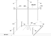
도 2는 본 발명의 일실시예에 따른 수중 측정센서 계류를 위한 중력 고정식 수중 계류 장치를 도시한 도면이고,
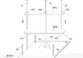
도 3은 본 발명의 일실시예에 따른 상부 플레이트가 해저 바닥면으로 이동한 것을 도시한 도면이다.The following drawings attached to the present specification illustrate a preferred embodiment of the present invention, and serve to further understand the technical spirit of the present invention together with the detailed description of the present invention, so the present invention is limited to the matters described in those drawings It should not be construed as being limited.
1 is a view showing a lower plate according to an embodiment of the present invention,
2 is a view showing a gravity-fixed underwater mooring device for mooring an underwater measurement sensor according to an embodiment of the present invention;
3 is a view showing the movement of the upper plate according to an embodiment of the present invention to the bottom of the sea.
이하, 도면을 참조하여 본 발명의 바람직한 일실시예에 대해서 설명한다. 또한, 이하에 설명하는 일실시예는 특허청구범위에 기재된 본 발명의 내용을 부당하게 한정하지 않으며, 본 실시 형태에서 설명되는 구성 전체가 본 발명의 해결 수단으로서 필수적이라고는 할 수 없다. 또한, 종래 기술 및 당업자에게 자명한 사항은 설명을 생략할 수도 있으며, 이러한 생략된 구성요소(방법) 및 기능의 설명은 본 발명의 기술적 사상을 벗어나지 아니하는 범위내에서 충분히 참조될 수 있을 것이다.Hereinafter, a preferred embodiment of the present invention will be described with reference to the drawings. In addition, one embodiment described below does not unreasonably limit the content of the present invention described in the claims, and it cannot be said that the entire configuration described in the present embodiment is essential as a solution for the present invention. In addition, descriptions of the prior art and matters obvious to those skilled in the art may be omitted, and the description of the omitted components (methods) and functions may be sufficiently referenced within the scope not departing from the technical spirit of the present invention.
본 발명의 일실시예에 따른 수중 측정센서 계류를 위한 중력 고정식 수중 계류 장치는 도 1 내지 도 3에 도시된 바와 같이 중력 고정식 하부 지지부(100), 이동식 상부 지지부(200), 부유식 삼각뿔 구조체(300), 수중 측정 센서부(400)를 포함함으로써 측정 해역에 부유식으로 고정되어 여러 가지 정보를 수집하도록 한 계류 장치이다. 이하에서는 첨부된 도면을 참고하여 본 발명의 일실시예에 따른 수중 측정센서 계류를 위한 중력 고정식 수중 계류 장치를 상세히 설명하기로 한다.Gravity-type underwater mooring device for mooring an underwater measurement sensor according to an embodiment of the present invention, as shown in FIGS. 1 to 3, a gravity fixed lower support part 100, a movable upper support part 200, a floating triangular pyramid structure ( 300), is a mooring device that is fixed to the measurement sea area by including the underwater measurement sensor unit 400 to collect various information. Hereinafter, a gravity-fixed underwater mooring device for mooring an underwater measurement sensor according to an embodiment of the present invention will be described in detail with reference to the accompanying drawings.
도 1 에 도시된 바와 같이 중력 고정식 하부 지지부(100)는 바지선 등에 의해 수면에서 견인되어 측정해역의 바닥으로 이동되며, 해저 바닥에 중력으로 고정된다. 중력 고정식 하부 지지부(100)의 하부 플레이트(101)는 대략적으로 388kg 정도의 무게가 있기 때문에 바지선 등에 의해 견인되어 측정 해역의 바닥면으로 이동될 수 있으며, 무게에 의해 해저 바닥면에 중력 고정될 수 있다.As shown in FIG. 1 , the gravity-fixed lower support part 100 is towed from the water surface by a barge or the like and moved to the bottom of the measurement area, and is fixed to the seabed by gravity. Since the
하부 플레이트(101)는 대략적으로 단면이 "직사각형 또는 정사각형" 형상으로 이루어진다. 하부 플레이트(101)의 4 모서리 영역에는 각각 제1,2,3,4 하부 플레이트 견인 고정부(121,122,123,124)가 배치 고정된다. 제1,2,3,4 하부 플레이트 견인 고정부(121,122,123,124)는 각각 견인 와이어를 결합 고정할 수 있는 결합 고정수단을 포함한다.The
제1,2,3,4 하부 플레이트 견인 와이어(21,22,23,24)의 일측 각각은 제1,2,3,4 하부 플레이트 견인 고정부(121,122,123,124)의 결합 고정수단에 각각 결합 고정된다. 제1,2,3,4 하부 플레이트 견인 와이어(21,22,23,24)의 타측 각각은 바지선에 각각 결합 고정된다. 따라서 하부 플레이트(101)를 견인하는 바지선이 제1,2,3,4 하부 플레이트 견인 와이어(21,22,23,24)를 통해 해저 바닥면으로 하부 플레이트(101)를 견인 이동시킨다. One side of the first, second, third, and fourth lower plate traction wires (21, 22, 23, 24) are respectively coupled and fixed to the coupling fixing means of the first, second, third, and fourth lower plate traction fixing parts (121, 122, 123, 124) . Each of the other sides of the first, second, third, and fourth lower plate traction wires (21, 22, 23, 24) is coupled and fixed to the barge, respectively. Accordingly, the barge towing the
하부 플레이트(101)에는 제1,2, 가이드 와이어 기둥부(111,112)가 각각 배치된다. 제1 가이드 와이어 기둥부(111)는 제1,3 하부 플레이트 견인 고정부(121,123)의 사이 공간에 배치 고정되며, 제2 가이드 와이어 기둥부(112)는 제2,4 하부 플레이트 견인 고정부(122,124)의 사이 공간에 배치 고정된다.The first, second, and guide
제1,2, 가이드 와이어 기둥부(111,112)는 일예로서 스테인리스 스틸 재질로 이루어지며, 내측으로 제1,2 상부 플레이트 가이드 와이어(11,12)가 삽입될 수 있는 지름을 가지는 것이 바람직하다. 제1,2 상부 플레이트 가이드 와이어(11,12)는 후술하는 상부 플레이트(201)가 해저 바닥면으로 이동할 때 가이드 하는 와이어이다. 제1,2 상부 플레이트 가이드 와이어(11,12)는 제1,2, 가이드 와이어 기둥부(111,112)에 삽입되면서 하부 플레이트(101)에 각각 결합 고정된다.The first and second
도 2에 도시된 바와 같이 이동식 상부 지지부(200)의 상부 플레이트(201)는 하부 플레이트(101)가 해저 바닥면에 중력 고정되면, 제1,2 상부 플레이트 가이드 와이어(11,12)에 의해 가이드 되어 하부 플레이트(101)로 내려 보낸다.As shown in FIG. 2 , the upper plate 201 of the movable upper support 200 is guided by the first and second upper
상부 플레이트(201)의 양측에는 제1,2 가이드 와이어 관통홈(211,212)이 형성된다. 제1,2 가이드 와이어 관통홈(211,212)은 제1,2 상부 플레이트 가이드 와이어(11,12) 및 제1,2 가이드 와이어 기둥부(111,112)가 통과될 수 있도록 지름이 형성되는 것이 바람직하다. 상부 플레이트(201)의 중심영역에는 상부 플레이트 견인 와이어 고정부(220)가 배치 고정된다. 상부 플레이트 견인 와이어 고정부(220)는 결합 고정수단을 구비하며, 결합 고정수단에 상부 플레이트 견인 와이어(31)가 결합 고정한다. 따라서 상부 플레이트(201)를 해저 바닥면으로 이동시킬 때, 상부 플레이트(201)는 양측에 배치된 제1,2 상부 플레이트 가이드 와이어(11,12)에 의해 가이드 되면서 동시에 상부 플레이트 견인 와이어(31)에 의해 견인되어 해저 바닥면으로 이동할 수 있다.First and second guide wire through
도 3에 도시된 바와 같이 하부 플레이트(101)가 먼저 해저 바닥면에 중력 고정된 후에 상부 플레이트(201a)가 해저 바닥면으로 제1,2 상부 플레이트 가이드 와이어(11,12)에 가이드 되면서 상부 플레이트 견인 와이어(31)에 의해 견인되어 해저 바닥면으로 이동한다. 이때, 상부 플레이트(201b)는 상부 플레이트 견인 와이어(31)의 견인 및 길이 조절에 따라 하부 플레이트(101)로부터 적절한 거리를 두고 떨어지면서 견인 고정된다. 상부 플레이트(201b)와 하부 플레이트(101)가 떨어진 거리 영역에는 후술하는 부유식 삼각뿔 구조체(300)가 배치 고정된다. 해저 바닥면으로 이동한 상부 플레이트(201b)는 제1,2 가이드 와이어 기둥부(111,112)를 통과한 후에 하부 플레이트(101)와 일정 거리 떨어져 배치 고정된다.As shown in FIG. 3 , after the
부유식 삼각뿔 구조체(300)는 걸림 고정수단을 구비하며, 걸림 고정수단은 걸림 고리에 걸림 고정된다. 걸림 고리는 상부 플레이트(201b)의 하부면에 배치 고정된 하부면 결합 고정수단에 결합 고정된다. 이에 따라 부유식 삼각뿔 구조체(300)는 하부 플레이트(101)로부터 플로팅되어 있으면서 상부 플레이트(201b)와 하부 플레이트(101)의 사이 공간에 배치 계류된다. 부유식 삼각뿔 구조체(300)의 내측에는 측정 해역의 각종 정보를 측정 및 수집하는 수중 측정 센서부(400)가 배치 고정된다. Floating triangular pyramid structure 300 is provided with a locking means, the locking means is fixed to the locking ring. The locking ring is fixed to the lower surface coupling fixing means arranged and fixed on the lower surface of the upper plate (201b). Accordingly, the floating triangular pyramid structure 300 is arranged and moored in the space between the
한편, 수중 측정 센서부(400)를 교체하기 위해서는 상부 플레이트 견인 와이어(31)를 끌어올린다. 상부 플레이트 견인 와이어(31)를 끌어올리면 양측에 있는 제1,2 상부 플레이트 가이드 와이어(11,12)에 의해 상부 플레이트(201)가 가이드 되면서 해수면 쪽으로 이동하며, 이와 동시에 상부 플레이트(201)에 걸림 고정된 부유식 삼각뿔 구조체(300) 및 수중 측정 센서부(400)도 함께 해수면 쪽으로 이동한다.On the other hand, in order to replace the underwater measurement sensor unit 400, the upper
본 발명을 설명함에 있어 종래 기술 및 당업자에게 자명한 사항은 설명을 생략할 수도 있으며, 이러한 생략된 구성요소(방법) 및 기능의 설명은 본 발명의 기술적 사상을 벗어나지 아니하는 범위내에서 충분히 참조될 수 있을 것이다. 또한, 상술한 본 발명의 구성요소는 본 발명의 설명의 편의를 위하여 설명하였을 뿐 여기에서 설명되지 아니한 구성요소가 본 발명의 기술적 사상을 벗어나지 아니하는 범위내에서 추가될 수 있다. In the description of the present invention, the description may be omitted for matters obvious to those skilled in the art and those skilled in the art, and the description of these omitted components (methods) and functions will be sufficiently referenced within the scope not departing from the technical spirit of the present invention. will be able In addition, the above-described components of the present invention have been described for convenience of description of the present invention, and components not described herein may be added within the scope without departing from the technical spirit of the present invention.
상술한 각부의 구성 및 기능에 대한 설명은 설명의 편의를 위하여 서로 분리하여 설명하였을 뿐 필요에 따라 어느 한 구성 및 기능이 다른 구성요소로 통합되어 구현되거나, 또는 더 세분화되어 구현될 수도 있다.The description of the configuration and function of each part has been described separately for convenience of description, and if necessary, one configuration and function may be implemented by being integrated into other components, or may be implemented more subdivided.
이상, 본 발명의 일실시예를 참조하여 설명했지만, 본 발명이 이것에 한정되지는 않으며, 다양한 변형 및 응용이 가능하다. 즉, 본 발명의 요지를 일탈하지 않는 범위에서 많은 변형이 가능한 것을 당업자는 용이하게 이해할 수 있을 것이다. 또한, 본 발명과 관련된 공지 기능 및 그 구성 또는 본 발명의 각 구성에 대한 결합관계에 대한 구체적인 설명이 본 발명의 요지를 불필요하게 흐릴 수 있다고 판단되는 경우에는, 그 구체적인 설명을 생략하였음에 유의해야 할 것이다.As mentioned above, although it has been described with reference to one embodiment of the present invention, the present invention is not limited thereto, and various modifications and applications are possible. That is, those skilled in the art will readily understand that many modifications are possible without departing from the gist of the present invention. In addition, it should be noted that, when it is determined that a detailed description of a known function related to the present invention and its configuration or a coupling relationship for each configuration of the present invention may unnecessarily obscure the gist of the present invention, the detailed description is omitted. something to do.
11 : 제1 상부 플레이트 가이드 와이어
12 : 제2 상부 플레이트 가이드 와이어
21 : 제1 하부 플레이트 견인 와이어
22 : 제2 하부 플레이트 견인 와이어
23 : 제3 하부 플레이트 견인 와이어
24 : 제4 하부 플레이트 견인 와이어
31 : 상부 플레이트 견인 와이어
100 : 중력 고정식 하부 지지부
101 : 하부 플레이트
111 : 제1 가이드 와이어 기둥부
112 : 제2 가이드 와이어 기둥부
121 : 제1 하부 플레이트 견인 고정부
122 : 제2 하부 플레이트 견인 고정부
123 : 제3 하부 플레이트 견인 고정부
124 : 제4 하부 플레이트 견인 고정부
200 : 이동식 상부 지지부
201,201a,201b : 상부 플레이트
211 : 제1 가이드 와이어 관통홈
212 : 제2 가이드 와이어 관통홈
220 : 상부 플레이트 견인 와이어 고정부
300 : 부유식 삼각뿔 구조체
400 : 수중 측정 센서부11: first upper plate guide wire
12: second upper plate guide wire
21: first lower plate traction wire
22: second lower plate traction wire
23: third lower plate traction wire
24: fourth lower plate traction wire
31: upper plate traction wire
100: gravity fixed lower support
101: lower plate
111: first guide wire pillar portion
112: second guide wire pillar portion
121: first lower plate traction fixing part
122: second lower plate traction fixing part
123: third lower plate traction fixing part
124: fourth lower plate traction fixing part
200: movable upper support
201,201a,201b: top plate
211: first guide wire through groove
212: second guide wire through groove
220: upper plate traction wire fixing part
300: floating triangular pyramid structure
400: underwater measurement sensor unit
Claims (4)
가이드 와이어를 따라 가이드 되어 상기 수중 측정해역의 바닥면으로 이동하는 이동식 상부 지지부,
상기 이동식 상부 지지부로부터 걸림 고정되는 부유식 삼각뿔 구조체,
상기 부유식 삼각뿔 구조체의 내측에 배치되어 상기 수중 측정해역의 정보를 센싱하는 수중 측정 센서부를 포함하는 것을 특징으로 하는 수중 측정센서 계류를 위한 중력 고정식 수중 계류 장치.
Gravity-fixed lower support that is moved to the bottom of the underwater measurement area by a traction wire and fixed by gravity;
A movable upper support part guided along the guide wire and moving to the bottom of the underwater measurement area;
A floating triangular pyramid structure that is caught and fixed from the movable upper support part,
A gravity-fixed underwater mooring device for mooring an underwater measurement sensor, characterized in that it is disposed inside the floating triangular pyramid structure and comprises an underwater measurement sensor unit for sensing information on the underwater measurement area.
상기 중력 고정식 하부 지지부는,
하부 플레이트의 양측에 각각 지지 고정되는 복수의 가이드 와이어 기둥부,
상기 하부 플레이트의 각 모서리에 고정되는 복수의 하부 플레이트 견인 고정부를 포함하는 것을 특징으로 하는 수중 측정센서 계류를 위한 중력 고정식 수중 계류 장치.
The method of claim 1,
The gravity fixed lower support portion,
A plurality of guide wire pillars respectively supported and fixed on both sides of the lower plate,
Gravity-fixed underwater mooring device for mooring an underwater measurement sensor, characterized in that it comprises a plurality of lower plate traction fixing parts fixed to each corner of the lower plate.
상기 복수의 하부 플레이트 견인 고정부에 각각 고정되어 상기 중력 고정식 하부 지지부를 상기 바닥면으로 견인 이동시키는 복수의 하부 플레이트 견인 와이어,
상기 복수의 가이드 와이어 기둥부의 내측으로 삽입되어 고정됨으로써 상기 이동식 상부 지지부가 상기 바닥면으로 이동할 때 상기 이동식 상부 지지부의 양측영역에서 가이드 하는 복수의 상부 플레이트 가이드 와이어,
상기 이동식 상부 지지부를 상기 바닥면으로 이동시킬 때 상기 이동식 상부 지지부의 중심영역에서 견인하는 상부 플레이트 견인 와이어를 포함하는 것을 특징으로 하는 수중 측정센서 계류를 위한 중력 고정식 수중 계류 장치.
3. The method of claim 2,
A plurality of lower plate traction wires that are respectively fixed to the plurality of lower plate traction fixing parts to traction and move the gravity fixed lower support part to the bottom surface;
A plurality of upper plate guide wires for guiding in both areas of the movable upper support part when the movable upper support part moves to the bottom surface by being inserted and fixed inside the plurality of guide wire pillar parts;
Gravity-fixed underwater mooring device for mooring an underwater measurement sensor, characterized in that it comprises an upper plate traction wire for pulling in a central region of the movable upper support when moving the movable upper support to the bottom surface.
상기 이동식 상부 지지부는,
상기 복수의 상부 플레이트 가이드 와이어가 각각 통과되도록 상부 플레이트의 양측에 각각 형성된 복수의 가이드 와이어 관통홈,
상기 상부 플레이트 견인 와이어가 고정되도록 상기 상부 플레이트의 중심에 배치되는 상부 플레이트 견인 와이어 고정부를 포함하는 것을 특징으로 하는 수중 측정센서 계류를 위한 중력 고정식 수중 계류 장치. 4. The method of claim 3,
The movable upper support part,
a plurality of guide wire through grooves respectively formed on both sides of the upper plate so that the plurality of upper plate guide wires pass through, respectively;
Gravity-fixed underwater mooring device for mooring an underwater measurement sensor, characterized in that it comprises an upper plate traction wire fixing part disposed at the center of the top plate so that the top plate traction wire is fixed.
Priority Applications (2)
| Application Number | Priority Date | Filing Date | Title |
|---|---|---|---|
| PCT/KR2020/017732 WO2022124427A1 (en) | 2020-12-07 | 2020-12-07 | Gravity-fixed underwater mooring device for mooring underwater measurement sensor |
| KR1020200169183A KR20220080264A (en) | 2020-12-07 | 2020-12-07 | Underwater mooring apparatus |
Applications Claiming Priority (1)
| Application Number | Priority Date | Filing Date | Title |
|---|---|---|---|
| KR1020200169183A KR20220080264A (en) | 2020-12-07 | 2020-12-07 | Underwater mooring apparatus |
Publications (1)
| Publication Number | Publication Date |
|---|---|
| KR20220080264A true KR20220080264A (en) | 2022-06-14 |
Family
ID=81973378
Family Applications (1)
| Application Number | Title | Priority Date | Filing Date |
|---|---|---|---|
| KR1020200169183A Ceased KR20220080264A (en) | 2020-12-07 | 2020-12-07 | Underwater mooring apparatus |
Country Status (2)
| Country | Link |
|---|---|
| KR (1) | KR20220080264A (en) |
| WO (1) | WO2022124427A1 (en) |
Citations (1)
| Publication number | Priority date | Publication date | Assignee | Title |
|---|---|---|---|---|
| KR101711285B1 (en) | 2015-05-14 | 2017-02-28 | 해주이엔씨 (주) | Device for tearing a net with mooring type in the sea water |
Family Cites Families (5)
| Publication number | Priority date | Publication date | Assignee | Title |
|---|---|---|---|---|
| US6418082B1 (en) * | 1999-06-30 | 2002-07-09 | Lockheed Martin Corporation | Bottom moored and tethered sensors for sensing amplitude and direction of pressure waves |
| KR100972396B1 (en) * | 2008-02-14 | 2010-07-27 | 주식회사 중원엔지니어링 | Water quality measuring device |
| KR200450558Y1 (en) * | 2008-08-13 | 2010-10-12 | 주식회사 중원엔지니어링 | Underwater floor detector |
| KR20140089932A (en) * | 2013-01-08 | 2014-07-16 | 지하정보기술(주) | Refloat Seabed Monitoring System having Self-defence Function from Dragnet |
| KR102171956B1 (en) * | 2019-04-18 | 2020-10-30 | 한국해양과학기술원 | Mounting frame of geoacoustic apparatus for measurement of sound speed and attenuation in sea floor sediment |
-
2020
- 2020-12-07 KR KR1020200169183A patent/KR20220080264A/en not_active Ceased
- 2020-12-07 WO PCT/KR2020/017732 patent/WO2022124427A1/en not_active Ceased
Patent Citations (1)
| Publication number | Priority date | Publication date | Assignee | Title |
|---|---|---|---|---|
| KR101711285B1 (en) | 2015-05-14 | 2017-02-28 | 해주이엔씨 (주) | Device for tearing a net with mooring type in the sea water |
Also Published As
| Publication number | Publication date |
|---|---|
| WO2022124427A1 (en) | 2022-06-16 |
Similar Documents
| Publication | Publication Date | Title |
|---|---|---|
| KR101536628B1 (en) | Model test apparatus of submerged body in towing tank with free motion type | |
| KR20140126022A (en) | mooring equipment of floating structure | |
| KR101820058B1 (en) | Apparatus inspecting the interior of the manhole | |
| DE3490708T1 (en) | MARINE SEISMIC SYSTEM | |
| KR101675527B1 (en) | Pontoon having device for maintaining tension of anchor | |
| KR101591741B1 (en) | 9 channel foldable fixed body 3 dimensional seismic exploration apparatus and method in small ships | |
| GB1578385A (en) | Apparatus for launching battered leg jackets for offshore platforms | |
| KR200469633Y1 (en) | depth-sounding apparatus | |
| WO2015099093A1 (en) | Sway reduction device and float provided with same | |
| US20160289907A1 (en) | Cable management for marine barriers and gate systems | |
| KR101859569B1 (en) | Data Collection System for Submarine Landform and Geographic Information | |
| JP2009007838A (en) | Underwater rubble leveling device and underwater rubble leveling method | |
| US20090202303A1 (en) | Enhanced wave power generators | |
| KR102384400B1 (en) | Folding 3-axis electric field sensors for under water | |
| CN205246071U (en) | On -board platform device of integrated mapping system under water on water | |
| KR920022318A (en) | A device for positioning a floating platform | |
| CN212388353U (en) | Underwater pier detection device | |
| KR102197558B1 (en) | Device for measuring the level of structures | |
| KR101635574B1 (en) | A loose-proof batten and Stage equipment to use it | |
| US10465822B2 (en) | Connection system for subsea pipelines | |
| CN111045014B (en) | Overwater geophysical prospecting detection scanning platform and method | |
| WO2022124427A1 (en) | Gravity-fixed underwater mooring device for mooring underwater measurement sensor | |
| JP2000203487A (en) | Floating mooring device | |
| KR102033529B1 (en) | Transverse connection method for floating marine structure | |
| KR101584571B1 (en) | Docking device and method for connecting floating dock and barge |
Legal Events
| Date | Code | Title | Description |
|---|---|---|---|
| A201 | Request for examination | ||
| PA0109 | Patent application |
Patent event code: PA01091R01D Comment text: Patent Application Patent event date: 20201207 |
|
| PA0201 | Request for examination | ||
| PG1501 | Laying open of application | ||
| E902 | Notification of reason for refusal | ||
| PE0902 | Notice of grounds for rejection |
Comment text: Notification of reason for refusal Patent event date: 20221121 Patent event code: PE09021S01D |
|
| E601 | Decision to refuse application | ||
| PE0601 | Decision on rejection of patent |
Patent event date: 20230227 Comment text: Decision to Refuse Application Patent event code: PE06012S01D Patent event date: 20221121 Comment text: Notification of reason for refusal Patent event code: PE06011S01I |