KR20220080385A - Socket for supporting closet rod - Google Patents
Socket for supporting closet rod Download PDFInfo
- Publication number
- KR20220080385A KR20220080385A KR1020200169430A KR20200169430A KR20220080385A KR 20220080385 A KR20220080385 A KR 20220080385A KR 1020200169430 A KR1020200169430 A KR 1020200169430A KR 20200169430 A KR20200169430 A KR 20200169430A KR 20220080385 A KR20220080385 A KR 20220080385A
- Authority
- KR
- South Korea
- Prior art keywords
- cover
- base
- hanger rod
- hanger
- socket
- Prior art date
- Legal status (The legal status is an assumption and is not a legal conclusion. Google has not performed a legal analysis and makes no representation as to the accuracy of the status listed.)
- Ceased
Links
Images

Classifications
-
- A—HUMAN NECESSITIES
- A47—FURNITURE; DOMESTIC ARTICLES OR APPLIANCES; COFFEE MILLS; SPICE MILLS; SUCTION CLEANERS IN GENERAL
- A47B—TABLES; DESKS; OFFICE FURNITURE; CABINETS; DRAWERS; GENERAL DETAILS OF FURNITURE
- A47B61/00—Wardrobes
- A47B61/003—Details of garment-holders
-
- A—HUMAN NECESSITIES
- A47—FURNITURE; DOMESTIC ARTICLES OR APPLIANCES; COFFEE MILLS; SPICE MILLS; SUCTION CLEANERS IN GENERAL
- A47B—TABLES; DESKS; OFFICE FURNITURE; CABINETS; DRAWERS; GENERAL DETAILS OF FURNITURE
- A47B2220/00—General furniture construction, e.g. fittings
- A47B2220/0036—Brackets
-
- A—HUMAN NECESSITIES
- A47—FURNITURE; DOMESTIC ARTICLES OR APPLIANCES; COFFEE MILLS; SPICE MILLS; SUCTION CLEANERS IN GENERAL
- A47B—TABLES; DESKS; OFFICE FURNITURE; CABINETS; DRAWERS; GENERAL DETAILS OF FURNITURE
- A47B2220/00—General furniture construction, e.g. fittings
- A47B2220/0061—Accessories
Landscapes
- Supports Or Holders For Household Use (AREA)
Abstract
본 발명은 베이스에 옷걸이 봉을 걸친 상태에서 커버를 씌워서 고정할 수 있게 구성함으로써, 베이스에 옷걸이 봉을 걸치기 전에 미리 옷걸이 봉에 커버를 끼우지 않고도 쉽고 편리하게 옷걸이 봉을 소켓에 조립할 수 있게 한 옷걸이 봉을 지지하는 소켓을 제공한다. 특히, 가구의 천장이나 벽면에 설치되는 베이스에 커버가 스냅 핏(Snap-fit) 방식으로 조립하거나 분리할 수 있게 구성함으로써, 베이스에 커버를 대고 누르면 쉽게 조립할 수 있게 한 옷걸이 봉을 지지하는 소켓을 제공한다. 또한, 커버의 한쪽을 옷걸이 봉에 끼운 상태에서 이 커버를 베이스에 마주하게 하여 조립할 수 있게 구성함으로써, 누구든지 쉽고 편리하게 베이스에 커버를 쉽게 조립하여 편리하게 사용할 수 있게 한 옷걸이 봉을 지지하는 소켓을 제공한다.The present invention is a hanger rod that allows the hanger rod to be easily and conveniently assembled into the socket without putting the cover on the hanger rod in advance before hanging the hanger rod on the base by covering it with the cover while the hanger rod is placed on the base. A socket is provided to support the In particular, by configuring the cover to be assembled or detached in a snap-fit method to the base installed on the ceiling or wall of furniture, the socket supporting the hanger bar can be easily assembled by pressing the cover on the base. to provide. In addition, by configuring the cover to face the base while assembling one side of the cover on the hanger bar, anyone can easily and conveniently assemble the cover on the base and use it conveniently. A socket supporting the hanger bar provides
Description
본 발명은 옷걸이 봉을 지지하는 소켓에 관한 것으로, 더욱 상세하게는 가구 등의 천장이나 벽면에 고정된 베이스에 옷걸이 봉을 걸친 상태에서 베이스에 커버를 조립하여 마감할 수 있게 구성함으로써, 커버를 옷걸이 봉에 끼우지 않고도 베이스에 커버를 조립할 수 있게 되어 조립 효율을 높일 수 있게 한 것이다. 이때, 커버는 베이스에 스냅 핏(Snap-fit) 방식으로 조립되거나 분리될 수 있게 구성함으로써, 때에 따라 쉽고 편리하게 분리하거나 조립할 수 있게 한 것이다.The present invention relates to a socket for supporting a hanger rod, and more particularly, by configuring the cover to be finished by assembling the cover to the base while the hanger rod is hung on the base fixed to the ceiling or wall surface of furniture, etc. It is possible to assemble the cover on the base without inserting it into the rod, thereby increasing the assembly efficiency. In this case, the cover is configured to be assembled or separated to the base in a snap-fit method, so that it can be easily and conveniently separated or assembled at times.
일반적으로 옷을 걸어두는 옷장과 같은 가구에는 한정된 공간에 많은 옷을 걸 수 있도록 적어도 하나의 옷걸이 봉이 구성된다. 이때, 옷걸이 봉은 가구의 천장이나 벽면에 고정된 소켓에 양단이 걸쳐지게 해서 옷걸이를 지지할 수 있게 구성한다. 이에, 옷걸이 봉은, 아래의 (특허문헌 1) 내지 (특허문헌 3)과 같이, 다양한 형태로 이루어진 소켓(또는 고정구)에 의해 지지 고정된다.In general, furniture such as a wardrobe for hanging clothes is configured with at least one hanger rod so that many clothes can be hung in a limited space. In this case, the hanger rod is configured to support the hanger by having both ends hang over the socket fixed to the ceiling or wall of the furniture. Accordingly, the hanger rod is supported and fixed by sockets (or fixtures) having various shapes as shown in the following (Patent Document 1) to (Patent Document 3).
(특허문헌 1) 한국공개특허 제10-2020-0059491호(Patent Document 1) Korean Patent Publication No. 10-2020-0059491
옷장의 좌·우 벽면 또는 천장 면에 설치되는 한 쌍의 옷걸이봉 고정구(bracket)에 관한 것으로, 하나의 고정구로 옷장 벽면에 일정간격으로 형성된 고정 홈에 손쉽고 견고하게 삽입하여 고정할 수 있게 하고 상기 고정 홈이 형성되지 않은 옷장 내벽에도 고정 설치할 수 있도록 하며 옷장의 천장 면에도 고정할 수 있도록 한 고정구에 관한 것이다. 상기 고정구는 옷걸이봉을 삽입하는 삽입 홈이 포함되고 방향제 및 탈취제를 보관하는 수납공간이 형성되며 수납공간 일면으로 통풍구가 형성되는 한편, 상부로 한 쌍의 제1 결합부와 하부로는 제2 결합부가 형성되는 본체; 상기 제1 결합부와 제2 결합부가 형성되고 통풍구가 형성되어 상기 본체의 수납공간 전면을 개폐하는 커버; 상기 본체의 삽입 홈에 형성된 결합 홈에 나사 결합하여 배면으로 돌출되는 고정 돌기; 상기 고정 돌기 일측으로 나사 형성되고 타측으로 방사형태의 탄성 편이 형성됨에 따라, 개폐 가능한 수납공간을 통해 탈취제 또는 방향제등을 보관할 수 있게 되고 상기 결합 홈에 결합된 고정 돌기에 의해 옷장 내벽의 고정 홈에 착탈 가능하게 할 수 있게 되고, 옷장 내벽에 고정 홈이 없는 경우에도 본체의 결합 홈을 통해 나사못으로 고정 설치할 수 있으며 'ㄱ'자 형의 고정 브래킷에 의해 옷장 천장 면에도 고정할 수 있음으로 하나의 고정구로 옷걸이봉을 사용할 수 있는 옷장용 옷걸이봉 고정구를 제공한다.It relates to a pair of hanger bar brackets installed on the left and right walls or ceiling surfaces of a wardrobe, and it is possible to easily and securely insert and fix it in a fixing groove formed at regular intervals on the wall of the wardrobe with one fastener, and the above It relates to a fixture that allows it to be fixedly installed on the inner wall of a wardrobe where a fixing groove is not formed and can also be fixed to the ceiling surface of the wardrobe. The fixture includes an insertion groove for inserting a hanger rod, a storage space for storing air fresheners and deodorants is formed, and a ventilation hole is formed on one surface of the storage space, while a pair of first coupling parts at the top and a second coupling at the bottom a body in which an addition is formed; a cover having the first coupling part and the second coupling part formed therein and having a ventilation hole to open and close the front of the storage space of the main body; a fixing protrusion which is screwed into the coupling groove formed in the insertion groove of the main body and protrudes toward the rear surface; As a screw is formed on one side of the fixing protrusion and a radial elastic piece is formed on the other side, a deodorant or air freshener can be stored through an openable and openable storage space, and by the fixing protrusion coupled to the coupling groove, in the fixing groove of the inner wall of the wardrobe. It can be made detachable, and even if there is no fixing groove on the inner wall of the wardrobe, it can be fixed and installed with screws through the coupling groove of the main body. It provides a hanger bar fixture for a wardrobe in which a hanger bar can be used as a fixture.
(특허문헌 2) 한국공개특허 제10-2020-0054795호(Patent Document 2) Korean Patent Publication No. 10-2020-0054795
가구용 옷걸이봉에 관한 것으로, 가구의 내부에 고정 설치되는 고정구; 상기 고정구에 탈착 가능하게 삽입되어 지지되는 옷봉; 및 상기 옷봉의 길이방향으로 이동 가능하게 상기 옷봉에 삽입되고, 상기 고정구의 일측에 끼워 맞추어져 상기 고정구와 상기 옷봉을 마감하는 마감캡;으로 구성되어 조립된 외관이 깔끔하고 미려하게 되고, 조립이 간편하고 견고하도록 한다.It relates to a furniture hanger rod, comprising: a fixture that is fixedly installed in the interior of furniture; a clothes bar that is detachably inserted and supported in the fixture; and a closing cap which is inserted into the clothes bar so as to be movable in the longitudinal direction of the clothes bar and is fitted to one side of the fixture to close the fixture and the clothes bar; and make it strong.
(특허문헌 3) 한국등록특허 제10-1867298호(Patent Document 3) Korean Patent No. 10-1867298
사용자의 키 또는 옷의 길이에 따라 옷장 내부에 설치된 옷걸이봉 조립체의 설치 높이를 적절하게 조절하여 사용할 수 있는 높이 조절이 가능한 옷걸이봉 조립체에 관한 것이다. 상기의 과제를 해결하기 위한 높이 조절이 가능한 옷걸이봉 조립체는, 수평의 길이를 가지면서 일단에 걸이 부재가 설치되는 제1 옷걸이봉; 일단에는 상기 제1 옷걸이봉의 타단이 삽입되고, 타단에는 걸이 부재가 설치되는 제2 옷걸이봉; 상기 제1, 2 옷걸이봉의 상기 걸이 부재에 각각 결합하여 고정되는 높이조절구; 및 옷장의 내부 양측 면에 각각 고정 설치되면서 상기 높이조절구가 삽입됨과 동시에 상하로 높이 조절 가능하게 안내하는 고정구를 포함하고, 상호 조립된 상기 제1, 2 옷걸이봉의 길이를 조절하여 상기 고정구로부터 위치 이동 또는 위치 고정되어 상하로 높이 조절되는 것을 특징으로 한다.The present invention relates to a height-adjustable clothes hanger bar assembly that can be used by appropriately adjusting the installation height of the hanger bar assembly installed inside the closet according to the user's height or the length of clothes. The height-adjustable clothes hanger bar assembly for solving the above problems includes: a first hanger bar having a horizontal length and having a hanging member installed at one end thereof; a second clothes hanger bar having one end inserted into the other end of the first hanger bar and having a hanger member installed at the other end thereof; a height adjuster fixed to each of the first and second hanger rods by being coupled to the hanging member; and a fixture for guiding the height adjustment tool up and down at the same time as being fixedly installed on both inner sides of the wardrobe, and adjusting the lengths of the first and second hanger rods assembled together to position them from the fixture It is characterized in that it is moved or the position is fixed and the height is adjusted up and down.
하지만, 이러한 기존의 옷걸이 봉 고정구는 다음과 같은 문제가 있다.However, these conventional hanger rod fixtures have the following problems.
(1) 옷걸이 봉을 걸쳐놓는 고정구에 커버를 씌워서 미감과 미관을 개선하게 되는데, 이때 커버가 옷걸이 봉에 끼워지게 해서 조립함에 따라 다음과 같은 문제가 발생한다.(1) The aesthetics and aesthetics are improved by putting a cover on the fixture on which the hanger rod is hung.
(2) 즉, 옷걸이 봉을 고정구에 걸쳐서 조립하기 전에 미리 커버를 고정구에 관통하게 끼운 상태에서 옷걸이 봉을 고정구에 걸쳐서 조립한 다음, 이 커버를 고정구에 조립해야 한다.(2) That is, before assembling the hanger bar over the fixture, insert the cover through the fixture in advance and assemble the hanger bar over the fixture, then assemble this cover to the fixture.
(3) 하지만, 때에 따라 옷걸이 봉에 커버를 삽입하지 않고 옷걸이 봉을 고정구에 걸쳐서 조립할 때가 종종 발생한다. 이는, 고정구에서 조립한 옷걸이 봉을 분리한 다음, 옷걸이 봉에 커버를 삽입한 뒤에 다시 옷걸이 봉을 고정구에 걸쳐서 조립하는 것을 반복해야 한다.(3) However, it often occurs when the hanger bar is assembled over the fixture without inserting the cover into the hanger bar. In this case, it is necessary to repeat the assembly of the hanger rod over the fixture after removing the assembled hanger rod from the fixture and inserting the cover into the hanger rod.
(4) 이에, 커버를 조립하는 시간이 길어져서 결과적으로 옷걸이 봉을 설치하는 조립 시간이 길어진다.(4) As a result, the time for assembling the cover becomes longer, and as a result, the time for assembling the hanger rod becomes longer.
본 발명은 이러한 점을 고려한 것으로, 베이스에 옷걸이 봉을 걸친 상태에서 커버를 씌워서 고정할 수 있게 구성함으로써, 베이스에 옷걸이 봉을 걸치기 전에 미리 옷걸이 봉에 커버를 끼우지 않고도 쉽고 편리하게 옷걸이 봉을 소켓에 조립할 수 있게 한 옷걸이 봉을 지지하는 소켓을 제공하는데 그 목적이 있다.The present invention is made in consideration of this point, and by configuring the cover to be fixed while the hanger rod is placed on the base, it is easy and convenient to attach the hanger rod to the socket without putting the cover on the hanger rod in advance before hanging the hanger rod on the base. An object of the present invention is to provide a socket for supporting a hanger rod that can be assembled.
특히, 본 발명은 가구의 천장이나 벽면에 설치되는 베이스에 커버가 스냅 핏(Snap-fit) 방식으로 조립하거나 분리할 수 있게 구성함으로써, 베이스에 커버를 대고 누르면 쉽게 조립할 수 있게 한 옷걸이 봉을 지지하는 소켓을 제공하는데 다른 목적이 있다.In particular, the present invention supports a hanger rod that can be easily assembled by pressing the cover against the base by configuring the cover to be assembled or separated in a snap-fit method to the base installed on the ceiling or wall of furniture. It serves another purpose to provide a socket for
또한, 본 발명은 커버의 한쪽을 옷걸이 봉에 끼운 상태에서 이 커버를 베이스에 마주하게 하여 조립할 수 있게 구성함으로써, 누구든지 쉽고 편리하게 베이스에 커버를 쉽게 조립하여 편리하게 사용할 수 있게 한 옷걸이 봉을 지지하는 소켓을 제공하는데 또 다른 목적이 있다.In addition, the present invention provides a hanger rod that allows anyone to easily and conveniently assemble the cover to the base and use it conveniently by configuring it to be assembled with the cover facing the base in a state where one side of the cover is inserted into the hanger rod. Another object is to provide a supporting socket.
이러한 목적을 달성하기 위한 본 발명에 따른 옷걸이 봉을 지지하는 소켓은, 가구 벽면에 고정될 수 있게 한쪽 면에 적어도 두 개의 제1체결 구멍(110)이 관통 형성되고, 한쪽에는 가구의 천장 면에 고정될 수 있도록 제2체결 구멍(120)이 관통 형성되며, 다른 한쪽에 상기 제2체결 구멍(120)이 형성된 부분보다 넓게 옷걸이 봉(B)을 걸칠 수 있도록 플랜지(130)가 돌출 형성된 베이스(100); 및 상기 플랜지(130)에 옷걸이 봉(B)이 걸쳐진 상태에서 이 옷걸이 봉(B)에 폭 방향으로 한쪽이 끼워지게 하면서 상기 베이스(100)에 스냅 핏 방식으로 고정되는 커버(200);가 포함된 것을 특징으로 한다.In order to achieve this object, the socket for supporting the hanger rod according to the present invention has at least two
특히, 상기 제2체결 구멍(120)이 형성된 상기 베이스(100)의 한쪽에는 상기 커버(200)와 마주하는 면의 폭 단면이 "T"자 형상으로 걸림 턱(140)이 형성되고; 상기 걸림 턱(140)과 마주하는 상기 커버(200)에는, 상기 걸림 턱(140)의 세로 부분이 강제로 끼워지거나 분리할 수 있도록 두 개의 압착 돌기(210)가 돌출 형성된 것을 특징으로 한다.In particular, on one side of the
또한, 상기 베이스(100)에는, 상기 플랜지(130)의 양측 면 외부에 턱(150)이 형성되되, 상기 턱(150)에는 상기 플랜지(130)에 걸쳐진 옷걸이 봉(B)을 감싸서 마감하도록 상기 커버(200)에 형성된 조립 홈(220)의 양쪽 가장자리가 걸쳐져서 하나의 면을 이루게 구성된 것을 특징으로 한다.In addition, the
마지막으로, 상기 플랜지(130)의 서로 마주하는 양쪽 면은 상기 커버(200) 안에 밀착하게 끼워지도록 구성되되, 양쪽에 각각 적어도 하나의 걸림 홈(131)이 형성되고; 상기 걸림 홈(131)과 마주하는 상기 커버(200)에는 상기 걸림 홈(131)에 강제로 끼워지거나 빠지도록 탄성 돌기(230)가 돌출 형성된 것을 특징으로 한다.Finally, both surfaces of the
본 발명에 따른 옷걸이 봉을 지지하는 소켓은 다음과 같은 효과가 있다.The socket for supporting the hanger rod according to the present invention has the following effects.
(1) 가구의 천장이나 벽면에 고정된 베이스에 옷걸이 봉을 걸친 상태에서도 쉽게 베이스에 커버를 씌워서 장착할 수 있다.(1) Even when the hanger rod is hung on the base fixed to the ceiling or wall of the furniture, it can be easily installed by covering the base with a cover.
(2) 이에, 베이스에서 걸친 옷걸이 봉을 분리해서 이 옷걸이 봉에 커버를 씌우는 과정을 생략할 수 있을 뿐만 아니라 이러한 과정을 반복함에 따라 조립 효율이 떨어지는 것을 방지할 수 있다.(2) Accordingly, it is possible to not only omit the process of separating the hanger rod from the base to put the cover on the hanger rod, but also to prevent the assembly efficiency from falling by repeating this process.
(3) 베이스에 커버를 고정할 때 스냅 핏(Snap-fit) 방식을 이용함으로, 베이스에 커버를 대고 누르면 쉽게 조립할 수 있어 누구든지 편리하고 간단하게 커버를 고정할 수 있다.(3) By using the snap-fit method when fixing the cover to the base, it can be easily assembled by pressing the cover on the base, so anyone can conveniently and simply fix the cover.
(4) 한편, 커버는 베이스에 형성된 턱에 걸쳐지게 하여 베이스를 향해 누름에 따라 돌기에 걸려 조립할 수 있게 구성함으로써, 때에 따라 베이스에서 커버를 쉽게 분리하여 필요한 작업 등을 할 수 있어 편리하다.(4) On the other hand, since the cover is configured to be hung over the chin formed on the base so that it can be assembled by hooking it on the protrusion when pressed toward the base, it is convenient because the cover can be easily separated from the base and necessary work can be performed at times.
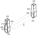
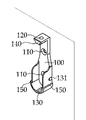
[도 1]은 본 발명에 따른 옷걸이 봉을 지지하는 소켓에 옷걸이 봉을 걸친 상태를 보여주는 사시도이다.
[도 2]는 본 발명에 따른 옷걸이 봉을 지지하는 소켓을 구성하는 베이스에 커버가 결합이 된 상태를 보여주는 사시도이다.
[도 3]은 본 발명에 따른 베이스에 커버가 결합이 되기 전 상태를 보여주는 분해 사시도이다.
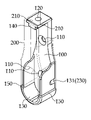
[도 4]는 본 발명에 따른 베이스의 전체 구성을 보여주는 사시도이다.
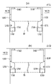
[도 5]는 본 발명에 따른 베이스를 가구 내에 고정된 상태를 보여주는 측면도로, (a)는 2개의 베이스가 가구의 양쪽 벽면에 고정된 상태를, (b)는 하나의 베이스는 벽면에 다른 하나의 베이스는 가구 천장에 각각 고정된 상태를 보여준다.
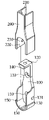
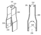
[도 6]은 본 발명에 따른 커버의 전체 구성을 보여주는 도면으로, (a)는 사시도이고, (b)는 배면도이다.
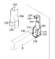
[도 7]은 본 발명에 따른 베이스가 가구 안에 고정된 상태를 보여주는 사시도이다.
[도 8]은 본 발명에 따라 가구 안에 고정된 베이스에 옷걸이 봉의 끝을 걸친 상태를 보여주는 사시도이다.
[도 9]는 본 발명에 따라 옷걸이 봉을 걸친 베이스에 커버를 씌워서 일체로 고정한 상태를 보여주는 사시도이다.[FIG. 1] is a perspective view showing a state in which a hanger rod is applied to a socket for supporting a hanger rod according to the present invention.
[Figure 2] is a perspective view showing a state in which the cover is coupled to the base constituting the socket for supporting the hanger rod according to the present invention.
[Figure 3] is an exploded perspective view showing a state before the cover is coupled to the base according to the present invention.
[Figure 4] is a perspective view showing the overall configuration of the base according to the present invention.
[Fig. 5] is a side view showing a state in which the base according to the present invention is fixed in the furniture, (a) is a state in which two bases are fixed to both walls of the furniture, (b) is a state in which one base is fixed to the wall and the other One base is each fixed to the furniture ceiling.
[Fig. 6] is a view showing the overall configuration of the cover according to the present invention, (a) is a perspective view, (b) is a rear view.
[Fig. 7] is a perspective view showing a state in which the base according to the present invention is fixed in the furniture.
[Fig. 8] is a perspective view showing a state in which the end of the hanger rod is hung on the base fixed in the furniture according to the present invention.
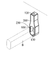
[Fig. 9] is a perspective view showing a state in which a cover is put on the base over which the hanger rod is applied according to the present invention and is integrally fixed.
이하, 첨부된 도면을 참조하여 본 발명의 바람직한 실시예를 더욱 상세히 설명하기로 한다. 이에 앞서, 본 명세서 및 청구범위에 사용된 용어나 단어는 통상적이거나 사전적인 의미로 한정해서 해석되어서는 안 되며, 발명자는 그 자신의 발명을 최고의 방법으로 설명하기 위해 용어의 개념을 적절하게 정의할 수 있다는 원칙에 따라 본 발명의 기술적 사상에 부합하는 의미와 개념으로 해석되어야만 한다.Hereinafter, preferred embodiments of the present invention will be described in more detail with reference to the accompanying drawings. Prior to this, the terms or words used in the present specification and claims should not be construed as being limited to their ordinary or dictionary meanings, and the inventor may properly define the concept of the term in order to best describe his invention. According to the principle that can be, it should be interpreted as meaning and concept consistent with the technical idea of the present invention.
따라서 본 명세서에 기재된 실시예와 도면에 도시된 구성은 본 발명의 가장 바람직한 일 실시예에 불과할 뿐이고 본 발명의 기술적 사상을 모두 대변하는 것은 아니므로, 본 출원 시점에서 이들을 대체할 수 있는 다양한 균등물과 변형례가 있을 수 있음을 이해하여야 한다.Therefore, since the embodiments described in this specification and the configurations shown in the drawings are only the most preferred embodiment of the present invention and do not represent all the technical spirit of the present invention, various equivalents that can be substituted for them at the time of the present application It should be understood that there may be variations and examples.
[소켓의 구성][Configuration of socket]
본 발명에 따른 옷걸이 봉을 지지하는 소켓에는, 베이스(100), 그리고 커버(200)가 포함된다.The socket for supporting the hanger rod according to the present invention includes a
특히, 상기 커버(200)는 가구의 벽면이나 천장에 고정된 베이스(100)에 옷걸이 봉(B)이 걸쳐진 상태에서도 이 베이스(100)에 조립할 수 있게 구성함으로써, 커버(200)를 옷걸이 봉(B)에 끼우지 않고도 쉽고 신속하게 조립할 수 있게 한 것이다.In particular, the
이때, 상기 커버(200)는 베이스(100)에 마주하게 끼우고 누르면 쉽게 조립되는 스냅 핏(Snap-fit) 방식으로 조립할 수 있게 구성함으로써, 누구든지 쉽고 편리하게 커버(200)를 조립하거나 때에 따라 베이스(100)에서 조립된 커버(200)를 분리할 수 있게 한 것이다.At this time, the
또한, 상기 커버(200)는 베이스(100)에 형성된 플랜지(130)를 감싸도록 끼워지되, 서로 마주하는 면에 걸림 홈(131)과 탄성 돌기(230)를 형성하여 탄성 변형을 이용하여 조립할 수 있게 구성함으로써, 커버(200)를 쉽게 조립했다가 때에 따라 쉽게 분리할 수 있게 한 것이다.In addition, the
이하, 이러한 구성에 관해 첨부도면을 참조하여 더욱 상세하게 설명하면 다음과 같다. 여기서, 도면부호 "B"는 옷걸이 등을 거는 옷걸이 봉을 나타낸다.Hereinafter, such a configuration will be described in more detail with reference to the accompanying drawings. Here, reference numeral "B" denotes a hanger rod for hanging a coat hanger or the like.
가. 베이스go. Base
베이스(100)는, [도 1] 내지 [도 5]와 같이, 가구의 벽면이나 천장에 고정하여 옷걸이 봉(B)의 끝을 지지할 수 있게 한다. 그리고 개방된 부분에는 후술할 커버(200)로 마감할 수 있게 구성된다.The
이러한 베이스(100)에는, [도 2] 내지 [도 5]와 같이, 제1체결 구멍(110), 제2체결 구멍(120), 플랜지(130)가 돌출 형성된다. 또한, 상기 베이스(100)에는 커버(200)를 스냅 핏 방식으로 고정할 수 있게 하는 걸림 턱(140)과 턱(150)이 추가로 구성된다.In this
1. 제1체결 구멍1. First fastening hole
제1체결 구멍(110)은, [도 2] 내지 [도 5(a)] 및 [도 7]과 같이, 베이스(100)의 한쪽 면에 적어도 두 개가 관통 형성된다. 이때, 제1체결 구멍(110)은 베이스(100)의 한쪽 면을 가구 벽면에 밀착하게 대고 스크루 등을 이용해서 베이스(100)를 고정하기 위한 구멍이다. 이러한 제1체결 구멍(110)은 베이스(100)의 길이에 따라 적어도 하나 관통 형성하는 것이 바람직하다.At least two of the first fastening holes 110 are formed through one side of the
2. 제2체결 구멍2. Second fastening hole
제2체결 구멍(120)은, [도 2] 내지 [도 4]와 같이, 상기 베이스(100)의 한쪽에 형성된다. 이때, 상기 제2체결 구멍(120)은 상술한 제1체결 구멍(110)과는 직각이 되게 베이스(100)의 한쪽이 꺾인 부분에 형성함으로써, [도 5(b)]와 같이, 옷걸이 봉(B)의 길이가 짧을 때는 이 베이스(100)를 가구 천장 면에 스크루 등을 이용해서 조립할 수 있게 한다. 즉, 상기 베이스(100)는 "ㄱ"자 형태가 되게 하여 세로 부분에는 제1체결 구멍(110)을 형성하여 가구의 벽면에 체결할 수 있게 하고, 가로 부분에는 제2체결 구멍(120)을 형성하여 가구의 천장 면에 밀착하게 해서 조립할 수 있게 한다. The
3. 플랜지3. Flange
플랜지(130)는, [도 2] 내지 [도 5]와 같이, 상술한 제2체결 구멍(120)과 마주하는 베이스(100)의 다른 한쪽에 형성된다. 이때, 상기 플랜지(130)는 상기 베이스(100)를 가구 천장이나 벽면에 고정한 상태에서 옷걸이 봉(B)의 끝이 걸쳐지게 하여 지지할 수 있게 구성한다.The
이를 위해, 상기 플랜지(130)는, [도 5] 및 [도 8]과 같이, 옷걸이 봉(B)의 외주를 감쌀 수 있는 형태로 제작하는 것이 바람직하다. 이때, 상기 플랜지(130)는 그 위에서 옷걸이 봉(B)의 끝 부분을 대고 삽입하면 이 옷걸이 봉(B)의 윗부분을 제외한 나머지 부분을 감싸면서 지지할 수 있게 형성하는 것이 가장 바람직하다.To this end, the
또한, 상기 플랜지(130)는, [도 1] 내지 [도 4]와 같이, 상술한 제2체결 구멍(120)이 형성된 쪽보다 넓게 형성함으로써, 후술할 커버(200)를 [도 3]과 같이 베이스(100) 위에서부터 끼울 때 쉽게 끼울 수 있게 형성하는 것이 바람직하다.In addition, the
한편, 상기 플랜지(130)에는, [도 2] 내지 [도 5]와 같이, 서로 마주하는 양쪽 면에 각각 적어도 하나의 걸림 홈(131)이 형성된다. 걸림 홈(131)은 이 플랜지(130)의 서로 마주하는 양쪽 면이 후술할 커버(200) 안쪽 면에 밀착하게 끼워질 때 이 커버(200)에 형성된 후술할 탄성 돌기(230)가 강제로 끼워지게 하여 쉽게 조립되게 하고, 강제로 분리할 때는 쉽게 분리될 수 있게 한다.On the other hand, in the
4. 걸림 턱4. Jaw Jaws
걸림 턱(140)은, [도 2] 내지 [도 4]와 같이, 상술한 제2체결 구멍(120)이 형성된 베이스(100)의 한쪽에 형성된다. 이때, 상기 걸림 턱(140)은 베이스(100)와 마주하여 커버(200)를 대고 이 커버(200)를 누르면 상기 걸림 턱(140)이 커버(200)의 후술할 압착 돌기(210) 사이에 강제로 끼게 하여 커버(200)를 베이스(100)에 고정할 수 있게 하기 위함이다. 이에, 상기 걸림 턱(140)은 커버(200)와 마주하는 베이스(100) 면에 폭 단면이 "T"자 형상으로 형성함으로써, 가로 부분에는 상술한 제2체결 구멍(120)을 형성하고, 세로 부분에는 후술할 두 개의 압착 돌기(210)가 강제로 끼게 하여 커버(200)를 베이스(100)에 강제로 끼워서 조립할 수 있게 한다.The locking
5. 턱5. chin
턱(150)은, [도 2] 내지 [도 5]와 같이, 상술한 플랜지(130)의 서로 마주하는 양쪽 면에 형성된다. 이때, 상기 플랜지(130)의 양쪽 면은 후술할 커버(200)에 끼워지게 되는데, 이때 이 커버(200)의 가장자리 부분이 이 턱(150)에 걸려 조립 위치를 쉽게 알 수 있게 할 뿐만 아니라 이들 베이스(100)와 커버(200)가 하나의 면을 이루게 하여 미감과 미관을 개선할 수 있게 한다. 물론, 이러한 턱(150)은 베이스(100)와 커버(200)가 하나의 면을 이루어지지 않더라도 상관은 없다.The
나. 커버me. cover
커버(200)는, [도 1] 내지 [도 3] 및 [도 6]과 같이, 상술한 베이스(100)에 걸쳐지게 지지가 된 옷걸이 봉(B)에 끼워지게 하면서 이 베이스(100)에 스냅 핏 방식으로 결합이 되어 마감할 수 있게 구성된다. 여기서, 스냅 핏(Snap-fit)은 손으로 눌러서 탄성 편이나 돌기가 구멍이나 턱에 걸려 쉽게 고정되게 하는 것을 말한다.The
이를 위해, 상기 커버(200)에는, [도 2]·[도 3] 및 [도 6]과 같이, 두 개의 압착 돌기(210), 조립 홈(220), 그리고 탄성 돌기(230)가 포함된다.To this end, the
1. 압착 돌기1. Pressing projection
압착 돌기(210)는, [도 2]·[도 3] 및 [도 6]과 같이, 상기 커버(200)를 베이스(100)에 조립하려고 마주하게 위치했을 때 상술한 걸림 턱(140)과 마주하는 위치에 형성된다. 이때, 상기 압착 돌기(210)는 두 개가 커버(200)에서 서로 마주하게 돌출 형성되고, 상기 베이스(100)에 커버(200)를 대고 누름에 따라 이들 압착 돌기(210) 사이에 턱(140)이 강제로 끼워지면서 베이스(100)에 커버(200)가 조립되게 한다.The
2. 조립 홈2. Assembly groove
조립 홈(220)은, [도 2]·[도 3] 및 [도 6]과 같이, 상술한 플랜지(130)에 걸쳐져서 지지가 된 옷걸이 봉(B)에 끼워질 수 있도록 커버(200) 한쪽에 형성된다. 이때, 상기 조립 홈(220)은 커버(200)를 상기 베이스(100)에 조립할 때, 이 베이스(100)에 걸쳐진 옷걸이 봉(B)의 폭 방향으로 미리 끼워서 마감할 수 있게 구성함으로써, 이처럼 옷걸이 봉(B)에 조립 홈(220)을 끼운 상태에서 커버(200)를 베이스(100)와 마주하게 하여 한 번에 바로 조립할 수 있게 구성된다.
이때, 상기 조립 홈(220)은 그 가장자리가, [도 2] 및 [도 8]과 같이, 상술한 턱(150)에 걸쳐지게 조립되게 구성함으로써, 정해진 위치에서 쉽게 조립할 수 있게 안내할 뿐만 아니라 베이스(100)와 커버(200)가 하나의 면을 이루게 하여 미감과 미관을 개선할 수 있게 한다.At this time, the assembling
3. 탄성 돌기3. Elastic protrusion
탄성 돌기(230)는, [도 2]·[도 3]·[도 6] 및 [도 8]과 같이, 상술한 플랜지(130)의 서로 마주하는 면이 커버(200)에 끼워질 때 이 마주하는 면에 형성된 걸림 홈(131)에 강제로 끼워져서 베이스(100)에 커버(200)를 고정하게 하는 돌기이다. 이러한 탄성 돌기(230)는 베이스(100)와 마주한 상태에서 커버(200)가 이 베이스(100)에 끼워짐에 따라 강제로 변형되었다가 상기 걸림 홈(131)에 걸려 베이스(100)에서 커버(200)가 이탈하는 것을 막아준다.The
이상과 같이 이루어진 본 발명은 가구의 벽면이나 천장에 고정된 베이스에 옷걸이 봉이 걸쳐서 지지가 된 상태에서도 쉽게 커버를 씌워서 일체로 조립할 수 있게 된다.According to the present invention made as described above, the cover can be easily put on the base fixed to the wall or ceiling of the furniture and assembled in one piece even when the hanger rod is supported.
100: 베이스
110, 120: 제1, 제2체결 구멍
130: 플랜지
131: 걸림 홈
140: 걸림 턱
150: 턱
200: 커버
210: 압착 돌기
220: 조립 홈
230: 탄성 돌기100: base
110, 120: first and second fastening holes
130: flange
131: jamming groove
140: jamming jaw
150: jaw
200: cover
210: pressing protrusion
220: assembly groove
230: elastic projection
Claims (4)
상기 플랜지(130)에 옷걸이 봉(B)이 걸쳐진 상태에서 이 옷걸이 봉(B)에 폭 방향으로 한쪽이 끼워지게 하면서 상기 베이스(100)에 스냅 핏 방식으로 고정되는 커버(200);가 포함된 것을 특징으로 하는 옷걸이 봉을 지지하는 소켓.
At least two first fastening holes 110 are formed through one side so as to be fixed to the furniture wall surface, and second fastening holes 120 are formed through one side to be fixed to the ceiling surface of the furniture, and the other side a base 100 on which a flange 130 protrudes so that the hanger rod (B) can be hung wider than the portion where the second fastening hole 120 is formed; and
A cover 200 fixed to the base 100 in a snap-fit manner while one side is fitted in the width direction to the hanger rod (B) in a state in which the hanger bar (B) is hung over the flange (130); A socket supporting the hanger rod, characterized in that.
상기 제2체결 구멍(120)이 형성된 상기 베이스(100)의 한쪽에는 상기 커버(200)와 마주하는 면의 폭 단면이 "T"자 형상으로 걸림 턱(140)이 형성되고,
상기 걸림 턱(140)과 마주하는 상기 커버(200)에는, 상기 걸림 턱(140)의 세로 부분이 강제로 끼워지거나 분리할 수 있도록 두 개의 압착 돌기(210)가 돌출 형성된 것을 특징으로 하는 옷걸이 봉을 지지하는 소켓.
In claim 1,
On one side of the base 100 in which the second fastening hole 120 is formed, a locking protrusion 140 is formed in a "T" shape with a cross-section of the surface facing the cover 200,
The cover 200 facing the locking jaw 140 has two pressing protrusions 210 protruding so that the vertical part of the locking jaw 140 can be forcibly fitted or separated. socket to support it.
상기 베이스(100)에는,
상기 플랜지(130)의 양측 면 외부에 턱(150)이 형성되되, 상기 턱(150)에는 상기 플랜지(130)에 걸쳐진 옷걸이 봉(B)을 감싸서 마감하도록 상기 커버(200)에 형성된 조립 홈(220)의 양쪽 가장자리가 걸쳐져서 하나의 면을 이루게 구성된 것을 특징으로 하는 옷걸이 봉을 지지하는 소켓.
In claim 1,
In the base 100,
An assembling groove formed in the cover 200 so as to wrap and finish the chin 150 is formed on both sides of the flange 130 on the outside of the chin 150 and the hanger rod B spanning the flange 130 ( 220) Socket for supporting a hanger rod, characterized in that configured to form a single side by being spanned.
상기 플랜지(130)의 서로 마주하는 양쪽 면은 상기 커버(200) 안에 밀착하게 끼워지도록 구성되되, 양쪽에 각각 적어도 하나의 걸림 홈(131)이 형성되고,
상기 걸림 홈(131)과 마주하는 상기 커버(200)에는 상기 걸림 홈(131)에 강제로 끼워지거나 빠지도록 탄성 돌기(230)가 돌출 형성된 것을 특징으로 하는 옷걸이 봉을 지지하는 소켓.According to any one of claims 1 to 3,
Both surfaces of the flange 130 facing each other are configured to fit closely in the cover 200, and at least one locking groove 131 is formed on both sides, respectively,
The cover 200 facing the locking groove 131 has an elastic protrusion 230 protruding so as to be forcibly inserted into or removed from the locking groove 131 .
Priority Applications (1)
| Application Number | Priority Date | Filing Date | Title |
|---|---|---|---|
| KR1020200169430A KR20220080385A (en) | 2020-12-07 | 2020-12-07 | Socket for supporting closet rod |
Applications Claiming Priority (1)
| Application Number | Priority Date | Filing Date | Title |
|---|---|---|---|
| KR1020200169430A KR20220080385A (en) | 2020-12-07 | 2020-12-07 | Socket for supporting closet rod |
Publications (1)
| Publication Number | Publication Date |
|---|---|
| KR20220080385A true KR20220080385A (en) | 2022-06-14 |
Family
ID=81980470
Family Applications (1)
| Application Number | Title | Priority Date | Filing Date |
|---|---|---|---|
| KR1020200169430A Ceased KR20220080385A (en) | 2020-12-07 | 2020-12-07 | Socket for supporting closet rod |
Country Status (1)
| Country | Link |
|---|---|
| KR (1) | KR20220080385A (en) |
Cited By (1)
| Publication number | Priority date | Publication date | Assignee | Title |
|---|---|---|---|---|
| KR102726912B1 (en) * | 2023-07-04 | 2024-11-06 | (주) 장성산업 | Seamless clothes hanger rod mounting bracket |
Citations (3)
| Publication number | Priority date | Publication date | Assignee | Title |
|---|---|---|---|---|
| KR101867298B1 (en) | 2018-01-17 | 2018-06-14 | 주식회사 카시모 | Height Adjustable Hanger |
| KR20200054795A (en) | 2018-11-12 | 2020-05-20 | (주)대진아트와이어 | Clothes hanger for furniture |
| KR20200059491A (en) | 2018-11-21 | 2020-05-29 | 김현식 | Clothes hanger pipe fittings |
-
2020
- 2020-12-07 KR KR1020200169430A patent/KR20220080385A/en not_active Ceased
Patent Citations (3)
| Publication number | Priority date | Publication date | Assignee | Title |
|---|---|---|---|---|
| KR101867298B1 (en) | 2018-01-17 | 2018-06-14 | 주식회사 카시모 | Height Adjustable Hanger |
| KR20200054795A (en) | 2018-11-12 | 2020-05-20 | (주)대진아트와이어 | Clothes hanger for furniture |
| KR20200059491A (en) | 2018-11-21 | 2020-05-29 | 김현식 | Clothes hanger pipe fittings |
Cited By (1)
| Publication number | Priority date | Publication date | Assignee | Title |
|---|---|---|---|---|
| KR102726912B1 (en) * | 2023-07-04 | 2024-11-06 | (주) 장성산업 | Seamless clothes hanger rod mounting bracket |
Similar Documents
| Publication | Publication Date | Title |
|---|---|---|
| US20140124598A1 (en) | Adjustable storage assembly | |
| ITMI20070588A1 (en) | DRAWER ON AT LEAST ONE SIDE WALL OF WOOD | |
| KR102203361B1 (en) | Clothes hanger for furniture | |
| US20200132249A1 (en) | Accessory mounting device | |
| KR20220080385A (en) | Socket for supporting closet rod | |
| CA2946632A1 (en) | Towel rack | |
| JP6836758B2 (en) | Hanger hook and wall utilization system using it | |
| US12433402B2 (en) | Storage system | |
| KR101833510B1 (en) | Bed drawer is equipped | |
| KR20200059491A (en) | Clothes hanger pipe fittings | |
| KR200363417Y1 (en) | construction structure of shelf | |
| KR100690160B1 (en) | Handle of the door for the refrigerator | |
| KR200397511Y1 (en) | A Hanger assembly | |
| KR20150096178A (en) | A clothes hanger | |
| KR101191311B1 (en) | Prefabricated kitchen shelves | |
| KR102726912B1 (en) | Seamless clothes hanger rod mounting bracket | |
| KR102124248B1 (en) | Furniture hangers | |
| KR200498595Y1 (en) | Multi-function hanger. | |
| JP3026016U (en) | Hanging shelf | |
| KR200167011Y1 (en) | Setting device for the toilet partition | |
| KR200445642Y1 (en) | Multi-purpose hanger with adjustable length | |
| JP5097549B2 (en) | Long cut flower packaging container | |
| KR200290741Y1 (en) | Wall sticking type a clothes hanger | |
| JP4937638B2 (en) | Chair hangers | |
| KR200393623Y1 (en) | A clothes hanger with folding multi-column hanging part |
Legal Events
| Date | Code | Title | Description |
|---|---|---|---|
| PA0109 | Patent application |
Patent event code: PA01091R01D Comment text: Patent Application Patent event date: 20201207 |
|
| PA0201 | Request for examination | ||
| PE0902 | Notice of grounds for rejection |
Comment text: Notification of reason for refusal Patent event date: 20220412 Patent event code: PE09021S01D |
|
| PG1501 | Laying open of application | ||
| E601 | Decision to refuse application | ||
| PE0601 | Decision on rejection of patent |
Patent event date: 20221020 Comment text: Decision to Refuse Application Patent event code: PE06012S01D Patent event date: 20220412 Comment text: Notification of reason for refusal Patent event code: PE06011S01I |
|
| E601 | Decision to refuse application | ||
| E801 | Decision on dismissal of amendment | ||
| PE0601 | Decision on rejection of patent |
Patent event date: 20230314 Comment text: Decision to Refuse Application Patent event code: PE06012S01D Patent event date: 20220412 Comment text: Notification of reason for refusal Patent event code: PE06011S01I |
|
| PE0801 | Dismissal of amendment |
Patent event code: PE08012E01D Comment text: Decision on Dismissal of Amendment Patent event date: 20230314 Patent event code: PE08011R01I Comment text: Amendment to Specification, etc. Patent event date: 20230220 Patent event code: PE08011R01I Comment text: Amendment to Specification, etc. Patent event date: 20220609 |