KR20230061663A - Battery system and electric vehicle comprising the same - Google Patents
Battery system and electric vehicle comprising the same Download PDFInfo
- Publication number
- KR20230061663A KR20230061663A KR1020210145894A KR20210145894A KR20230061663A KR 20230061663 A KR20230061663 A KR 20230061663A KR 1020210145894 A KR1020210145894 A KR 1020210145894A KR 20210145894 A KR20210145894 A KR 20210145894A KR 20230061663 A KR20230061663 A KR 20230061663A
- Authority
- KR
- South Korea
- Prior art keywords
- voltage
- battery
- output
- low
- converter
- Prior art date
- Legal status (The legal status is an assumption and is not a legal conclusion. Google has not performed a legal analysis and makes no representation as to the accuracy of the status listed.)
- Pending
Links
Images

Classifications
-
- H—ELECTRICITY
- H02—GENERATION; CONVERSION OR DISTRIBUTION OF ELECTRIC POWER
- H02J—ELECTRIC POWER NETWORKS; CIRCUIT ARRANGEMENTS OR SYSTEMS FOR SUPPLYING OR DISTRIBUTING ELECTRIC POWER; SYSTEMS FOR STORING ELECTRIC ENERGY
- H02J7/00—Circuit arrangements for charging or discharging batteries or for supplying loads from batteries
- H02J7/34—Parallel operation in networks using both storage and other DC sources, e.g. providing buffering
-
- B—PERFORMING OPERATIONS; TRANSPORTING
- B60—VEHICLES IN GENERAL
- B60L—PROPULSION OF ELECTRICALLY-PROPELLED VEHICLES; SUPPLYING ELECTRIC POWER FOR AUXILIARY EQUIPMENT OF ELECTRICALLY-PROPELLED VEHICLES; ELECTRODYNAMIC BRAKE SYSTEMS FOR VEHICLES IN GENERAL; MAGNETIC SUSPENSION OR LEVITATION FOR VEHICLES; MONITORING OPERATING VARIABLES OF ELECTRICALLY-PROPELLED VEHICLES; ELECTRIC SAFETY DEVICES FOR ELECTRICALLY-PROPELLED VEHICLES
- B60L53/00—Methods of charging batteries, specially adapted for electric vehicles; Charging stations or on-board charging equipment therefor; Exchange of energy storage elements in electric vehicles
- B60L53/20—Methods of charging batteries, specially adapted for electric vehicles; Charging stations or on-board charging equipment therefor; Exchange of energy storage elements in electric vehicles characterised by converters located in the vehicle
- B60L53/24—Using the vehicle's propulsion converter for charging
-
- G—PHYSICS
- G01—MEASURING; TESTING
- G01R—MEASURING ELECTRIC VARIABLES; MEASURING MAGNETIC VARIABLES
- G01R19/00—Arrangements for measuring currents or voltages or for indicating presence or sign thereof
- G01R19/165—Indicating that current or voltage is either above or below a predetermined value or within or outside a predetermined range of values
- G01R19/16533—Indicating that current or voltage is either above or below a predetermined value or within or outside a predetermined range of values characterised by the application
- G01R19/16538—Indicating that current or voltage is either above or below a predetermined value or within or outside a predetermined range of values characterised by the application in AC or DC supplies
- G01R19/16542—Indicating that current or voltage is either above or below a predetermined value or within or outside a predetermined range of values characterised by the application in AC or DC supplies for batteries
-
- H02J7/007182—
-
- H—ELECTRICITY
- H02—GENERATION; CONVERSION OR DISTRIBUTION OF ELECTRIC POWER
- H02J—ELECTRIC POWER NETWORKS; CIRCUIT ARRANGEMENTS OR SYSTEMS FOR SUPPLYING OR DISTRIBUTING ELECTRIC POWER; SYSTEMS FOR STORING ELECTRIC ENERGY
- H02J7/00—Circuit arrangements for charging or discharging batteries or for supplying loads from batteries
- H02J7/90—Regulation of charging or discharging current or voltage
- H02J7/96—Regulation of charging or discharging current or voltage in response to battery voltage
-
- H—ELECTRICITY
- H02—GENERATION; CONVERSION OR DISTRIBUTION OF ELECTRIC POWER
- H02M—APPARATUS FOR CONVERSION BETWEEN AC AND AC, BETWEEN AC AND DC, OR BETWEEN DC AND DC, AND FOR USE WITH MAINS OR SIMILAR POWER SUPPLY SYSTEMS; CONVERSION OF DC OR AC INPUT POWER INTO SURGE OUTPUT POWER; CONTROL OR REGULATION THEREOF
- H02M3/00—Conversion of DC power input into DC power output
- H02M3/22—Conversion of DC power input into DC power output with intermediate conversion into AC
- H02M3/24—Conversion of DC power input into DC power output with intermediate conversion into AC by static converters
- H02M3/28—Conversion of DC power input into DC power output with intermediate conversion into AC by static converters using discharge tubes with control electrode or semiconductor devices with control electrode to produce the intermediate AC
- H02M3/325—Conversion of DC power input into DC power output with intermediate conversion into AC by static converters using discharge tubes with control electrode or semiconductor devices with control electrode to produce the intermediate AC using devices of a triode or a transistor type requiring continuous application of a control signal
- H02M3/335—Conversion of DC power input into DC power output with intermediate conversion into AC by static converters using discharge tubes with control electrode or semiconductor devices with control electrode to produce the intermediate AC using devices of a triode or a transistor type requiring continuous application of a control signal using semiconductor devices only
- H02M3/337—Conversion of DC power input into DC power output with intermediate conversion into AC by static converters using discharge tubes with control electrode or semiconductor devices with control electrode to produce the intermediate AC using devices of a triode or a transistor type requiring continuous application of a control signal using semiconductor devices only in push-pull configuration
-
- B—PERFORMING OPERATIONS; TRANSPORTING
- B60—VEHICLES IN GENERAL
- B60L—PROPULSION OF ELECTRICALLY-PROPELLED VEHICLES; SUPPLYING ELECTRIC POWER FOR AUXILIARY EQUIPMENT OF ELECTRICALLY-PROPELLED VEHICLES; ELECTRODYNAMIC BRAKE SYSTEMS FOR VEHICLES IN GENERAL; MAGNETIC SUSPENSION OR LEVITATION FOR VEHICLES; MONITORING OPERATING VARIABLES OF ELECTRICALLY-PROPELLED VEHICLES; ELECTRIC SAFETY DEVICES FOR ELECTRICALLY-PROPELLED VEHICLES
- B60L2210/00—Converter types
- B60L2210/10—DC to DC converters
-
- B—PERFORMING OPERATIONS; TRANSPORTING
- B60—VEHICLES IN GENERAL
- B60L—PROPULSION OF ELECTRICALLY-PROPELLED VEHICLES; SUPPLYING ELECTRIC POWER FOR AUXILIARY EQUIPMENT OF ELECTRICALLY-PROPELLED VEHICLES; ELECTRODYNAMIC BRAKE SYSTEMS FOR VEHICLES IN GENERAL; MAGNETIC SUSPENSION OR LEVITATION FOR VEHICLES; MONITORING OPERATING VARIABLES OF ELECTRICALLY-PROPELLED VEHICLES; ELECTRIC SAFETY DEVICES FOR ELECTRICALLY-PROPELLED VEHICLES
- B60L2240/00—Control parameters of input or output; Target parameters
- B60L2240/40—Drive Train control parameters
- B60L2240/54—Drive Train control parameters related to batteries
- B60L2240/547—Voltage
-
- B—PERFORMING OPERATIONS; TRANSPORTING
- B60—VEHICLES IN GENERAL
- B60Y—INDEXING SCHEME RELATING TO ASPECTS CROSS-CUTTING VEHICLE TECHNOLOGY
- B60Y2200/00—Type of vehicle
- B60Y2200/90—Vehicles comprising electric prime movers
- B60Y2200/91—Electric vehicles
-
- H—ELECTRICITY
- H02—GENERATION; CONVERSION OR DISTRIBUTION OF ELECTRIC POWER
- H02J—ELECTRIC POWER NETWORKS; CIRCUIT ARRANGEMENTS OR SYSTEMS FOR SUPPLYING OR DISTRIBUTING ELECTRIC POWER; SYSTEMS FOR STORING ELECTRIC ENERGY
- H02J2207/00—Details of circuit arrangements for charging or discharging batteries or supplying loads from batteries
- H02J2207/10—Control circuit supply, e.g. means for supplying power to the control circuit
-
- H—ELECTRICITY
- H02—GENERATION; CONVERSION OR DISTRIBUTION OF ELECTRIC POWER
- H02J—ELECTRIC POWER NETWORKS; CIRCUIT ARRANGEMENTS OR SYSTEMS FOR SUPPLYING OR DISTRIBUTING ELECTRIC POWER; SYSTEMS FOR STORING ELECTRIC ENERGY
- H02J2207/00—Details of circuit arrangements for charging or discharging batteries or supplying loads from batteries
- H02J2207/20—Charging or discharging characterised by the power electronics converter
-
- Y—GENERAL TAGGING OF NEW TECHNOLOGICAL DEVELOPMENTS; GENERAL TAGGING OF CROSS-SECTIONAL TECHNOLOGIES SPANNING OVER SEVERAL SECTIONS OF THE IPC; TECHNICAL SUBJECTS COVERED BY FORMER USPC CROSS-REFERENCE ART COLLECTIONS [XRACs] AND DIGESTS
- Y02—TECHNOLOGIES OR APPLICATIONS FOR MITIGATION OR ADAPTATION AGAINST CLIMATE CHANGE
- Y02T—CLIMATE CHANGE MITIGATION TECHNOLOGIES RELATED TO TRANSPORTATION
- Y02T10/00—Road transport of goods or passengers
- Y02T10/60—Other road transportation technologies with climate change mitigation effect
- Y02T10/70—Energy storage systems for electromobility, e.g. batteries
-
- Y—GENERAL TAGGING OF NEW TECHNOLOGICAL DEVELOPMENTS; GENERAL TAGGING OF CROSS-SECTIONAL TECHNOLOGIES SPANNING OVER SEVERAL SECTIONS OF THE IPC; TECHNICAL SUBJECTS COVERED BY FORMER USPC CROSS-REFERENCE ART COLLECTIONS [XRACs] AND DIGESTS
- Y02—TECHNOLOGIES OR APPLICATIONS FOR MITIGATION OR ADAPTATION AGAINST CLIMATE CHANGE
- Y02T—CLIMATE CHANGE MITIGATION TECHNOLOGIES RELATED TO TRANSPORTATION
- Y02T10/00—Road transport of goods or passengers
- Y02T10/60—Other road transportation technologies with climate change mitigation effect
- Y02T10/7072—Electromobility specific charging systems or methods for batteries, ultracapacitors, supercapacitors or double-layer capacitors
Landscapes
- Engineering & Computer Science (AREA)
- Power Engineering (AREA)
- Transportation (AREA)
- Mechanical Engineering (AREA)
- Physics & Mathematics (AREA)
- General Physics & Mathematics (AREA)
- Charge And Discharge Circuits For Batteries Or The Like (AREA)
Abstract
배터리 시스템은, 복수의 배터리 셀을 포함하는 고전압 배터리, 상기 고전압 배터리를 관리하는 배터리 관리 시스템, 상기 고전압 배터리보다 낮은 저전압을 상기 배터리 관리 시스템에 공급하는 저전압 배터리, 상기 고전압 배터리의 양극 및 음극 사이의 배터리 전압을 공급받아 제1 출력 전압을 생성하는 DC-DC 컨버터, 및 상기 저전압 배터리의 출력 전압에 대응하는 감지 전압이 소정의 임계전압 보다 작을 때, 상기 DC-DC 컨버터의 출력 전압을 상기 배터리 관리 시스템 및 상기 저전압 배터리에 공급하는 전력 스위칭 회로를 포함할 수 있다. A battery system includes a high voltage battery including a plurality of battery cells, a battery management system for managing the high voltage battery, a low voltage battery for supplying a low voltage lower than that of the high voltage battery to the battery management system, and a battery between an anode and a cathode of the high voltage battery. A DC-DC converter that receives a battery voltage and generates a first output voltage, and when a sensing voltage corresponding to the output voltage of the low-voltage battery is less than a predetermined threshold voltage, the output voltage of the DC-DC converter is set to the battery management A system and a power switching circuit supplying the low voltage battery.

Description
본 개시는 배터리 시스템 및 이를 포함하는 전기차에 관한 것이다. The present disclosure relates to a battery system and an electric vehicle including the same.
전기차에 장착되는 배터리는 차량 구동을 위한 전력을 공급하는 고전압 배터리와 차량에 구비된 전장품에 전력을 공급하는 저전압 배터리를 포함할 수 있다. 이때, 저전압 배터리는 차량의 전장품 뿐만 아니라 고전압 배터리의 배터리 관리 시스템에도 전력을 공급할 수 있다.A battery installed in an electric vehicle may include a high-voltage battery that supplies power for driving the vehicle and a low-voltage battery that supplies power to electrical components included in the vehicle. In this case, the low voltage battery may supply power not only to electric components of the vehicle but also to the battery management system of the high voltage battery.
저전압 배터리가 배터리 관리 시스템의 전원인 경우, 저전압 배터리가 동작하지 않을 경우 고전압 배터리에 대한 진단이 수행되지 않는 문제가 발생할 수 있다. 이를 방지하기 위해서, 저전압 배터리의 방전 또는 셧다운과 같은 고장에 대한 대응 기술 또는 저전압 배터리를 대체할 수 있는 기술이 필요하다. When the low-voltage battery is a power source of the battery management system, a diagnosis of the high-voltage battery may not be performed when the low-voltage battery does not operate. In order to prevent this, a technique for responding to a failure such as discharging or shutting down the low-voltage battery or a technique for replacing the low-voltage battery is required.
저전압 배터리의 이상에 의해 고전압 배터리의 진단이 수행되지 않는 문제를 해결하기 위한 배터리 시스템 및 이를 포함하는 전기차를 제공하고자 한다. An object of the present invention is to provide a battery system and an electric vehicle including the battery system to solve a problem in which a high voltage battery is not diagnosed due to an abnormality of a low voltage battery.
발명의 한 특징에 따른 배터리 시스템은, 복수의 배터리 셀을 포함하는 고전압 배터리, 상기 고전압 배터리를 관리하는 배터리 관리 시스템, 상기 고전압 배터리보다 낮은 저전압을 상기 배터리 관리 시스템에 공급하는 저전압 배터리, 상기 고전압 배터리의 양극 및 음극 사이의 배터리 전압을 공급받아 제1 출력 전압을 생성하는 DC-DC 컨버터, 및 상기 저전압 배터리의 출력 전압에 대응하는 감지 전압이 소정의 임계전압 보다 작을 때, 상기 DC-DC 컨버터의 출력 전압을 상기 배터리 관리 시스템 및 상기 저전압 배터리에 공급하는 전력 스위칭 회로를 포함할 수 있다. A battery system according to one aspect of the present invention includes a high voltage battery including a plurality of battery cells, a battery management system managing the high voltage battery, a low voltage battery supplying a low voltage lower than that of the high voltage battery to the battery management system, and the high voltage battery. A DC-DC converter generating a first output voltage by receiving the battery voltage between the positive and negative electrodes of the low-voltage battery, and when the detection voltage corresponding to the output voltage of the low-voltage battery is less than a predetermined threshold voltage, the DC-DC converter and a power switching circuit supplying an output voltage to the battery management system and the low voltage battery.
상기 전력 스위칭 회로는, 상기 DC-DC 컨버터의 출력단과, 상기 저전압 배터리의 충전 단자 및 상기 배터리 관리 시스템 사이에 연결되어 있는 연결 스위치, 상기 연결 스위치의 제어단에 연결된 푸시-풀 회로, 및 상기 푸시-풀 회로의 제어단에 연결된 일단을 포함하고, 상기 감지 전압과 상기 임계 전압 비교 결과에 따라 동작하는 제어 트랜지스터를 포함할 수 있다.The power switching circuit includes a connection switch connected between an output terminal of the DC-DC converter, a charging terminal of the low voltage battery and the battery management system, a push-pull circuit connected to a control terminal of the connection switch, and the push-pull circuit. - A control transistor including one end connected to the control terminal of the full circuit and operating according to a result of comparing the sensing voltage and the threshold voltage.
상기 푸시-풀 회로는, 상기 DC-DC 컨버터의 출력단과 상기 연결 스위치의 제어단 사이에 연결되어 있는 제1 트랜지스터 및 상기 연결 스위치의 제어단과 그라운드 사이에 연결되어 있는 제2 트랜지스터를 포함할 수 있다.The push-pull circuit may include a first transistor connected between an output terminal of the DC-DC converter and a control terminal of the connection switch, and a second transistor connected between a control terminal of the connection switch and a ground. .
상기 전력 스위칭 회로는, 상기 감지 전압과 상기 임계 전압을 비교하는 비교 회로를 더 포함하고, 상기 비교 회로는 상기 감지 전압이 상기 임계 전압 이하일 때 상기 제어 트랜지스터를 온 시키는 출력을 생성하고, 상기 감지 전압이 상기 임계 전압 보다 높을 때 상기 제어 트랜지스터를 오프 시키는 출력을 생성할 수 있다.The power switching circuit further includes a comparison circuit that compares the sensing voltage with the threshold voltage, wherein the comparison circuit generates an output that turns on the control transistor when the sensing voltage is less than or equal to the threshold voltage, and the sensing voltage When the voltage is higher than the threshold voltage, an output that turns off the control transistor may be generated.
상기 제어 트랜지스터가 온 되면 상기 푸시-풀 회로에 의해 상기 연결 스위치가 온 되고, 상기 제어 트랜지스터가 오프 되면 상기 푸시-풀 회로에 의해 상기 연결 스위치가 오프 될 수 있다.When the control transistor is turned on, the connection switch may be turned on by the push-pull circuit, and when the control transistor is turned off, the connection switch may be turned off by the push-pull circuit.
상기 배터리 시스템은, 상기 저전압 배터리의 출력 전압 및 상기 DC-DC 컨버터의 출력 전압 중 더 높은 전압을 선택하여 상기 배터리 관리 시스템에 공급하는 전압 선택부를 더 포함할 수 있다.The battery system may further include a voltage selector configured to select a higher voltage among the output voltage of the low-voltage battery and the output voltage of the DC-DC converter and supply the selected voltage to the battery management system.
발명의 다른 특징에 따른 전기차는, 배터리 시스템, 상기 배터리 시스템으로부터 공급되는 전력을 변환하여 부하에 공급하는 인버터, 및 상기 배터리 시스템으로부터 전력을 공급받는 전자 기기를 포함할 수 있다. 상기 배터리 시스템은, 복수의 배터리 셀을 포함하고, 상기 인버터에 연결되어 있는 고전압 배터리, 상기 고전압 배터리보다 낮은 저전압을 상기 전자 기기에 공급하는 저전압 배터리, 상기 고전압 배터리의 양극 및 음극 사이의 배터리 전압을 공급받아 제1 출력 전압을 생성하는 DC-DC 컨버터, 및 상기 저전압 배터리의 출력 전압에 대응하는 감지 전압이 소정의 임계전압 보다 작을 때, 상기 DC-DC 컨버터의 출력 전압을 상기 전자 기기 및 상기 저전압 배터리에 공급하는 전력 스위칭 회로를 포함할 수 있다. An electric vehicle according to another feature of the present invention may include a battery system, an inverter converting power supplied from the battery system and supplying the converted power to a load, and an electronic device receiving power from the battery system. The battery system includes a high voltage battery including a plurality of battery cells and connected to the inverter, a low voltage battery supplying a lower voltage than the high voltage battery to the electronic device, and a battery voltage between an anode and a cathode of the high voltage battery. A DC-DC converter that is supplied and generates a first output voltage, and when a sensing voltage corresponding to an output voltage of the low-voltage battery is less than a predetermined threshold voltage, the output voltage of the DC-DC converter is set to the electronic device and the low voltage It may include a power switching circuit that supplies power to the battery.
상기 전력 스위칭 회로는, 상기 DC-DC 컨버터의 출력단과, 상기 전자 기기 및 상기 저전압 배터리의 충전 단자 사이에 연결되어 있는 연결 스위치, 상기 연결 스위치의 제어단에 연결된 푸시-풀 회로, 및 상기 푸시-풀 회로의 제어단에 연결된 일단을 포함하고, 상기 감지 전압과 상기 임계 전압 비교 결과에 따라 동작하는 제어 트랜지스터를 포함할 수 있다. The power switching circuit includes a connection switch connected between an output terminal of the DC-DC converter and a charging terminal of the electronic device and the low-voltage battery, a push-pull circuit connected to a control terminal of the connection switch, and the push-pull circuit. A control transistor including one end connected to the control terminal of the pull circuit and operating according to a result of comparing the sensing voltage and the threshold voltage.
상기 전력 스위칭 회로는, 상기 감지 전압과 상기 임계 전압을 비교하는 비교 회로를 더 포함하고, 상기 비교 회로는 상기 감지 전압이 상기 임계 전압 이하일 때 상기 제어 트랜지스터를 온 시키는 출력을 생성하고, 상기 감지 전압이 상기 임계 전압 보다 높을 때 상기 제어 트랜지스터를 오프 시키는 출력을 생성할 수 있다.The power switching circuit further includes a comparison circuit that compares the sensing voltage with the threshold voltage, wherein the comparison circuit generates an output that turns on the control transistor when the sensing voltage is less than or equal to the threshold voltage, and the sensing voltage When the voltage is higher than the threshold voltage, an output that turns off the control transistor may be generated.
상기 제어 트랜지스터가 온 되면 상기 푸시-풀 회로에 의해 상기 연결 스위치가 온 되고, 상기 제어 트랜지스터가 오프 되면 상기 푸시-풀 회로에 의해 상기 연결 스위치가 오프 될 수 있다.When the control transistor is turned on, the connection switch may be turned on by the push-pull circuit, and when the control transistor is turned off, the connection switch may be turned off by the push-pull circuit.
상기 배터리 시스템은, 상기 고전압 배터리를 관리하는 배터리 관리 시스템을 더 포함하고, 상기 저전압 배터리의 출력 전압에 대응하는 감지 전압이 소정의 임계전압 보다 작을 때, 상기 DC-DC 컨버터의 출력 전압이 상기 전력 스위칭 회로를 통해 상기 배터리 관리 시스템에 공급될 수 있다.The battery system may further include a battery management system that manages the high voltage battery, and when a detected voltage corresponding to an output voltage of the low voltage battery is less than a predetermined threshold voltage, an output voltage of the DC-DC converter determines the power It may be supplied to the battery management system through a switching circuit.
상기 배터리 시스템은, 상기 저전압 배터리의 출력 전압 및 상기 DC-DC 컨버터의 출력 전압 중 더 높은 전압을 선택하여 상기 전자 기기 및 상기 배터리 관리 시스템에 공급하는 전압 선택부를 더 포함할 수 있다. The battery system may further include a voltage selection unit that selects a higher voltage among the output voltage of the low-voltage battery and the output voltage of the DC-DC converter and supplies it to the electronic device and the battery management system.
상기 배터리 시스템은, 상기 저전압 배터리의 출력 전압 및 상기 DC-DC 컨버터의 출력 전압 중 더 높은 전압을 선택하여 상기 전자 기기에 공급하는 전압 선택부를 더 포함할 수 있다. The battery system may further include a voltage selector configured to select a higher voltage among the output voltage of the low-voltage battery and the output voltage of the DC-DC converter and supply the selected voltage to the electronic device.
저전압 배터리의 이상에 의해 고전압 배터리의 진단이 수행되지 않는 문제를 해결하기 위한 배터리 시스템 및 이를 포함하는 전기차를 제공한다. Provided is a battery system for solving a problem in which a high voltage battery is not diagnosed due to an abnormality of a low voltage battery and an electric vehicle including the same.
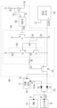
도 1은 일 실시예에 따른 배터리 시스템을 적용된 전기차를 도식적으로 나타낸 도면이다.
도 2는 일 실시예에 따른 전력 스위칭 회로를 나타낸 도면이다.1 is a diagram schematically illustrating an electric vehicle to which a battery system according to an exemplary embodiment is applied.
2 is a diagram illustrating a power switching circuit according to an exemplary embodiment.
이하, 첨부된 도면을 참조하여 본 명세서에 개시된 실시예를 상세히 설명하되, 동일하거나 유사한 구성요소에는 동일, 유사한 도면부호를 부여하고 이에 대한 중복되는 설명은 생략하기로 한다. 이하의 설명에서 사용되는 구성요소에 대한 접미사 "모듈" 및/또는 "부"는 명세서 작성의 용이함만이 고려되어 부여되거나 혼용되는 것으로서, 그 자체로 서로 구별되는 의미 또는 역할을 갖는 것은 아니다. 또한, 본 명세서에 개시된 실시예를 설명함에 있어서 관련된 공지 기술에 대한 구체적인 설명이 본 명세서에 개시된 실시예의 요지를 흐릴 수 있다고 판단되는 경우 그 상세한 설명을 생략한다. 또한, 첨부된 도면은 본 명세서에 개시된 실시예를 쉽게 이해할 수 있도록 하기 위한 것일 뿐, 첨부된 도면에 의해 본 명세서에 개시된 기술적 사상이 제한되지 않으며, 본 발명의 사상 및 기술 범위에 포함되는 모든 변경, 균등물 내지 대체물을 포함하는 것으로 이해되어야 한다.Hereinafter, the embodiments disclosed in this specification will be described in detail with reference to the accompanying drawings, but the same or similar reference numerals are given to the same or similar components, and overlapping descriptions thereof will be omitted. The suffixes "module" and/or "unit" for components used in the following description are given or used interchangeably in consideration of ease of writing the specification, and do not themselves have a meaning or role distinct from each other. In addition, in describing the embodiments disclosed in this specification, if it is determined that a detailed description of a related known technology may obscure the gist of the embodiment disclosed in this specification, the detailed description thereof will be omitted. In addition, the accompanying drawings are only for easy understanding of the embodiments disclosed in this specification, the technical idea disclosed in this specification is not limited by the accompanying drawings, and all changes included in the spirit and technical scope of the present invention , it should be understood to include equivalents or substitutes.
제1, 제2 등과 같이 서수를 포함하는 용어는 다양한 구성요소들을 설명하는데 사용될 수 있지만, 상기 구성요소들은 상기 용어들에 의해 한정되지는 않는다. 상기 용어들은 하나의 구성요소를 다른 구성요소로부터 구별하는 목적으로만 사용된다.Terms including ordinal numbers, such as first and second, may be used to describe various components, but the components are not limited by the terms. These terms are only used for the purpose of distinguishing one component from another.
본 출원에서, "포함한다" 또는 "가지다" 등의 용어는 명세서상에 기재된 특징, 숫자, 단계, 동작, 구성요소, 부품 또는 이들을 조합한 것이 존재함을 지정하려는 것이지, 하나 또는 그 이상의 다른 특징들이나 숫자, 단계, 동작, 구성요소, 부품 또는 이들을 조합한 것들의 존재 또는 부가 가능성을 미리 배제하지 않는 것으로 이해되어야 한다.In this application, terms such as "comprise" or "have" are intended to designate that there is a feature, number, step, operation, component, part, or combination thereof described in the specification, but one or more other features It should be understood that the presence or addition of numbers, steps, operations, components, parts, or combinations thereof is not precluded.
일 실시예에 따른 구성들 중 특정 제어 조건에서 다른 구성을 제어하는 구성에는, 다른 구성을 제어하기 위해 필요한 제어 알고리즘을 구체화한 명령어의 집합으로 구현된 프로그램이 설치될 수 있다. 제어 구성은 설치된 프로그램에 따라 입력 데이터 및 저장된 데이터를 처리하여 출력 데이터를 생성할 수 있다. 제어 구성은 프로그램을 저장하는 비휘발성 메모리 및 데이터를 저장하는 메모리를 포함할 수 있다. A program implemented as a set of commands embodying control algorithms necessary for controlling other components may be installed in a component that controls another component under a specific control condition among components according to an embodiment. The control component may generate output data by processing input data and stored data according to an installed program. The control component may include a non-volatile memory for storing programs and a memory for storing data.
이하, 도면을 참조하여, 일 실시예에 따른 전기차용 배터리 시스템을 설명한다. 전기차는 내연 기관 없이 모터로만 구동되는 차량, 내연 기관과 모터를 모두 포함하는 하이브리드 차량 등을 포함한다.Hereinafter, a battery system for an electric vehicle according to an embodiment will be described with reference to the drawings. An electric vehicle includes a vehicle driven only by a motor without an internal combustion engine, a hybrid vehicle including both an internal combustion engine and a motor, and the like.
도 1은 일 실시예에 따른 배터리 시스템을 적용된 전기차를 도식적으로 나타낸 도면이다.1 is a diagram schematically illustrating an electric vehicle to which a battery system according to an exemplary embodiment is applied.
전기차(1)는 배터리 시스템(10), 인버터(20), 모터(30), 및 전자 기기(40)를 포함한다. 모터(30)는 인버터(20)에 연결될 수 있는 전기차(1)의 전장 부하 중 일 예이다. The electric vehicle 1 includes a
인버터(20)는 배터리 시스템(10)의 고전압 배터리(100)으로부터 공급되는 전력을 변환하여 모터(30)에 공급할 수 있다.The inverter 20 may convert power supplied from the
전자 기기(40)는 전기차(1)에서 모터(30)를 제외한 다양한 종류의 전장 부하를 포함할 수 있다. 예를 들어, 전가 기기(40)는 블랙박스, 전기차(1)의 동작을 제어하는 다양한 종류의 전자 제어 장치, 속도 센서, 스위치, 스피커, 램프 등과 같이 전류가 흘러 전력을 소비하는 모든 종류의 전장 부하를 포함할 수 있다. The
모터(30)는 인버터(20)로부터 공급되는 전력에 따라 전기차(1)의 휠이 연결된 휠 축에 동력을 공급한다. The motor 30 supplies power to the wheel shaft to which the wheels of the electric vehicle 1 are connected according to the power supplied from the inverter 20 .
배터리 시스템(10)은 고전압 배터리(100), 배터리 관리 시스템(Battery Management System, BMS)(110), 컨텍터(120, 130), DC-DC 컨버터(140), 저전압 배터리(150), 전력 스위칭 회로(160), 및 전압 선택부(170)를 포함한다. The
고전압 배터리(100)는 직렬 연결된 복수의 배터리 셀(100_1~100_n)을 포함할 수 있다. 고전압 배터리(100)의 양극(P+) 및 음극(P-)은 컨택터(120, 130)의 제어에 따라 인버터(20)두 입력단(IN1, IN2)에 연결되거나 분리될 수 있다. 고전압 배터리(100)의 양극(P+) 및 음극(P-)은 DC-DC 컨버터(140)의 두 입력단(IN3, IN4)에 연결되어 있다. The
BMS(110)는 고전압 배터리(100)에 흐르는 배터리 전류, 고전압 배터리(100)의 온도, 및 복수의 배터리 셀(100_1~100_n)의 복수의 셀 전압에 대한 정보를 획득하여, 고전압 배터리(100)의 충방전을 제어하며, 복수의 배터리 셀(100_1~100_n)에 대한 셀 밸런싱 동작을 제어하고, 고전압 배터리(100)에서 발생할 수 있는 이상을 진단할 수 있다.The
컨택터(120)는 고전압 배터리(100)의 양극(P+)과 인버터(20)의 입력단(IN1) 사이에 연결되어 있고, 컨택터(130)는 고전압 배터리(100)의 음극(P-)과 인버터(20)의 입력단(IN2) 사이에 연결되어 있다. 컨택터(120, 130)는 BMS(110)의 제어에 따라 열리거나 닫힐 수 있다. 고전압 배터리(100)로부터 모터(30)로 전력이 공급될 때 BMS(110)의 제어에 의해 컨택터(120, 130)가 닫힐 수 있다.The
저전압 배터리(150)는 전자 기기(40) 및 BMS(110)에 전력을 공급할 수 있다. 저전압 배터리(150)의 양극에 연결된 출력 단자(P3)의 출력 전압(VOUT1)이 전자 기기(40) 및 BMS(110)의 전원 전압으로 공급될 수 있다. The
DC-DC 컨버터(140)의 입력단(IN3)은 고전압 배터리(100)의 양극(P+)에 연결되어 있고, 입력단(IN4)은 고전압 배터리(100)의 음극(P-)에 연결되어 있다. DC-DC 컨버터(140)는 고전압 배터리(100)의 양극(+)과 음극(-) 사이의 배터리 전압(VB)을 변환하여 출력 전압(VOUT2)을 생성하고, 연결 스위치(161)가 온 되어 있는 기간 동안, 출력 전압(VOUT2)이 전자 기기(40), BMS(110), 및 저전압 배터리(150)에 공급될 수 있다. 즉, DC-DC 컨버터(140)의 출력 전압(VOUT2)이 전자 기기(40) 및 BMS(110)의 전원 전압으로 공급될 수 있고, DC-DC 컨버터(140)은 저전압 배터리(150)를 충전할 수 있다. DC-DC 컨버터(140)는 고전압 배터리(100)의 배터리 전압(VB)을 전자 기기(40), BMS(110), 및 저전압 배터리(150)의 충전에 적합한 레벨의 출력 전압(VOUT2)으로 변환할 수 있는 다양한 방식의 컨버터로 구현될 수 있다. The input terminal IN3 of the DC-
이와 같이, 일 실시예에 따른 배터리 시스템(10)은 출력 전압(VOUT1)의 레벨에 따라, 전자 기기(40) 및 BMS(110)에 출력 전압(VOUT1) 및 출력 전압(VOUT2) 중 하나를 선택적으로 공급하고, 저전압 배터리(150)의 충방전을 제어할 수 있다. 저전압 배터리(150)의 출력 전압(VOUT1)이 소정의 임계치 이상일 때는 전자 기기(40) 및 BMS(110)는 저전압 배터리(150)로부터 전력을 공급받는다. 저전압 배터리(150)의 출력 전압(VOUT1)이 소정의 임계치 보다 낮아지면, DC-DC 컨버터(140)에 의해 충전되고, 전자 기기(40) 및 BMS(110)는 DC-DC 컨버터(140)로부터 전력을 공급 받을 수 있다. In this way, the
전력 스위칭 회로(160)는 저전압 배터리(150)의 출력 전압(VOUT1)을 측정하고, 측정된 전압(이하, 감지 전압)이 소정의 임계 전압(소정의 임계치에 대응하는 전압) 이하일 때 연결 스위치(161)를 온 시키고, 감지 전압이 임계 전압 보다 높을 때 연결 스위치(161)를 오프 시킨다. 전력 스위칭 회로(160)는 연결 스위치(161)의 스위칭 동작을 제어하는 게이트 전압(VG)을 생성할 수 있다. The
전압 선택부(170)는 두 출력 전압(VOUT1)을 입력받고, 두 출력 전압(VOUT1, VOUT2) 중 높은 전압을 출력한다. 전압 선택부(170)의 출력 전압은 “VOUT”으로 표시한다. 출력 전압(VOUT1)이 임계치 이하로 감소할 때 연결 스위치(161)가 온 되어 출력 전압(VOUT2)이 DC-DC 컨버터(140)로부터 전압 선택부(170)로 입력된다. 출력 전압(VOUT1)이 임계치 보다 높은 전압일 때는 출력 전압(VOUT1)만 전압 선택부(170)에 입력된다. 따라서, 전압 선택부(170)는 출력 전압(VOUT1)이 임계치 이하일 때 출력 전압(VOUT2)을 출력하고, 출력 전압(VOUT1)이 임계치 보다 높을 때 출력 전압(VOUT1)을 출력할 수 있다.The
BMS(110)는 전원 전압을 공급받는 단자(P1)를 포함하고, 단자(P1)에는 전압 선택부(170)의 출력 전압(VOUT)이 공급된다. 전자 기기(40)도 전원 전압을 공급받는 단자(P2)를 포함하고, 단자(P2)에는 전압 선택부(170)의 출력 전압(VOUT)이 공급된다. The
저전압 배터리(150)는 출력 단자(P3) 및 DC-DC 컨버터(140)에 연결된 충전 단자(P4)를 포함할 수 있다. 출력 단자(P3)는 전압 선택부(170)에 연결되어 있고, 출력 단자(P3)를 통해 출력 전압(VOUT1)이 출력된다. 연결 스위치(161)의 온 기간 동안 DC-DC 컨버터(140)의 출력 전압(VOUT2)이 충전 단자(P4)를 통해 저전압 배터리(150)에 공급되고, 저전압 배터리(150)는 출력 전압(VOUT2)에 의해 충전될 수 있다. 충전 단자(P4)는 저전압 배터리(150)의 양극에 연결될 수 있다. The
도 2는 일 실시예에 따른 전력 스위칭 회로를 나타낸 도면이다.2 is a diagram illustrating a power switching circuit according to an exemplary embodiment.
전력 스위칭 회로(160)는 연결 스위치(161), 비교 회로(162), 및 게이트 구동 회로(163)를 포함한다. 도 1에 도시된 연결 제어부(165)는 비교 회로(162) 및 게이트 구동 회로(163)로 구현될 수 있다. The
도 2에서 전압 선택부(170)는 두 개이 다이오드(D1, D2)를 포함하는 것으로 도시되어 있다. 전압 선택부(170)의 동작을 설명하기 위한 일 예로 발명이 이에 한정되는 것은 아니다. 다이오드(D1)의 애노드는 연결 스위치(161)의 드레인 단자에 연결되어 있고, 다이오드(D2)의 애노드는 저전압 배터리(150)의 출력 단자(P3)에 연결되어 있으며, 다이오드(D1, D2)의 캐소도는 단자(P1, P2)에 연결되어 있다.In FIG. 2 , the
감지 전압(VS)은 두 개의 저항(R1, R2)에 의해 전압 분배된 출력 전압(VOUT1)일 수 있다. 저전압 배터리(150)의 출력 단자(P3)는 직렬 연결된 두 저항(R1, R2) 중 하나인 저항(R1)의 일단에 연결되어 있고, 두 저항(R1, R2)는 접점(N4)과 그라운드 사이에 직렬 연결되어 있다. 일 실시예에서 연결 스위치(161)는 p 채널 타입의 트랜지스터로 구현되었다. 그러나 발명이 이에 한정되는 것은 아니고, 다른 채널 타입의 트랜지스터로 연결 스위치(161)가 구현될 수 있다. 아울러, 도 2에서 연결 스위치(161)가 하나의 트랜지스터로 구현된 것처럼 도시되어 있으나, 복수의 트랜지스터가 병렬 연결되어 연결 스위치(161)를 구현할 수 있다. The sensing voltage VS may be an output voltage VOUT1 voltage-divided by two resistors R1 and R2. The output terminal P3 of the
비교 회로(162)는 감지 전압(VS)과 임계 전압(Vth)을 비교한 결과에 따라 게이트 제어 신호(VGC)를 생성한다. 예를 들어, 비교 회로(162)는 감지 전압(VS)이 임계 전압(Vth) 보다 클 때 로우 레벨의 게이트 제어 신호(VGC)를 생성하고, 감지 전압(VS)이 임계 전압(Vth) 이하일 때 하이 레벨의 게이트 제어 신호(VGC)를 생성할 수 있다.The
게이트 구동 회로(163)는 제어 트랜지스터(T1) 및 푸시-풀 회로(164)를 포함한다. The
제어 트랜지스터(T1)는 비교 회로(162)의 출력인 게이트 제어 신호(VGC)에 따라 스위칭한다. 일 실시예에서 제어 트랜지스터(T1)는 n 채널 타입의 트랜지스터로 구현되어 있다. 따라서 제어 트랜지스터(T1)는 하이 레벨의 게이트 제어 신호(VGC)에 의해 턴 온 되고, 로우 레벨의 게이트 제어 신호(VGC)에 의해 턴 오프 된다.The control transistor T1 switches according to the gate control signal VGC, which is an output of the
두 저항(R3, R4)은 DC-DC 컨버터(140)의 출력단(N1)과 제어 트랜지스터(T1)의 드레인 사이에 직렬 연결되어 있다. 두 저항(R3, R4)이 연결된 접전(N2)은 푸시-풀 회로(164)를 구성하는 두 BJT(T2, T3)의 제어 단자인 베이스 단자에 연결되어 있다. BJT(T2)는 npn BJT로, BJT(T2)의 컬렉터 단자는 출력단(N1)에 연결되어 있고, BJT(T2)의 에미터 단자는 접점(N3)에 연결되어 있다. BJT(T3)는 pnp BJT로, BJT(T3)의 에미터 단자는 접점(N3)에 연결되어 있고, BJT(T3)의 컬렉터 단자는 저항(R5)의 일단에 연결되어 있으며, 저항(R5)의 타단은 그라운드에 연결되어 있다. 두 BJT(T2, T3)의 에미터 단자가 연결된 접점(N3)은 저항(R6)을 통해 연결 스위치(161)의 게이트 단자에 연결되어 있다. 저항(T6)을 통해 연결 스위치(161)의 게이트 단자에 공급되는 전압이 게이트 전압(VG)이다. 연결 스위치(161)의 소스 단자는 출력단(N1)에 연결되어 있고, 연결 스위치(161)의 드레인 단자는 전자 기기(40) 및 BMS(110)에 연결되어 있을 수 있다. Two resistors R3 and R4 are connected in series between the output terminal N1 of the DC-
제어 트랜지스터(T1)가 오프 상태일 때, 접점(N2)의 전압은 출력 전압(VOUT2)에 의해 BJT(T2)는 온 상태이고, BJT(T3)는 오프 상태이다. BJT(T2)를 통해 흐르는 전류에 의해 연결 스위치(161)의 게이트 단자 전압이 하이 레벨 전압이 되어 연결 스위치(161)는 오프(개방) 상태이다. 제어 트랜지스터(T1)가 온 상태일 때, 접점(N2)의 전압은 출력 전압(VOUT2)이 두 저항(R3, R4)에 의해 저항 분배된 전압이고, 접점(N2)의 전압에 의해 BJT(T3)는 온 상태이고, BJT(T2)는 오프 상태이다. BJT(T3)를 통해 흐르는 전류에 의해 연결 스위치(161)의 게이트 단자 전압이 로우 레벨 전압이 되어 연결 스위치(161)는 온(닫힘) 상태이다. When the control transistor T1 is in an off state, the voltage at the contact point N2 is an output voltage VOUT2, so that the BJT (T2) is in an on state and the BJT (T3) is in an off state. The gate terminal voltage of the
저전압 배터리(150)가 방전되어 출력 전압(VOUT1)이 감소하면, 감지 전압(VS) 역시 감소한다. 감지 전압(VS)이 임계 전압(Vth) 이하가 되면, 비교 회로(162)는 하이 레벨의 게이트 제어 신호(VGC)를 생성한다. 그러면, 제어 트랜지스터(T1)가 턴 온 되어, 연결 스위치(161)이 턴 온 된다. When the
온 상태인 연결 스위치(161)를 통해 DC-DC 컨버터(140)의 출력 전압(VOUT2)이 다이오드(D1)의 애노드에 공급되고, 저전압 배터리(150)의 출력 전압(VOUT1) 보다 출력 전압(VOUT2)이 높아 다이오드(D1)이 도통된다. 그러면, 다이오드(D1, D2)의 캐소드 전압은 출력 전압(VOUT2)이 되고, 다이오드(D2)는 역 바이어스에 의해 차단되며, 출력 전압(VOUT2)이 전자 기기(40) 및 BMS(110)에 공급된다. 이로써, 저전압 배터리가 방전 또는 고장에 의해 동작하지 않을 경우 BMS가 동작하지 않아 고전압 배터리에 대한 진단이 수행되지 않는 문제가 방지할 수 있다.The output voltage VOUT2 of the DC-
연결 스위치(161)의 온 기간 동안, 저전압 배터리(150)의 충전 단자(P4)를 통해 출력 전압(VOUT2)이 저전압 배터리(150)에 공급되어, 저전압 배터리(150)가 충전된다. 그러면, 저전압 배터리(150)의 출력 전압(VOUT1)이 증가할 수 있다. 출력 전압(VOUT1)이 증가하여 임계치 보다 높아지면, 감지 전압(VS)이 임계 전압(Vth) 보다 높은 전압이 될 수 있다. 그러면, 비교회로(162)는 로우 레벨의 게이트 제어 신호(VGC)를 생성하고 제어 트랜지스터(T1)가 턴 오프 되어, 연결 스위치(161)가 턴 오프 될 수 있다. During the ON period of the
연결 스위치(161)가 오프가 되면, 다이오드(D1)의 애노드는 플로팅 상태로 전압이 감소하여 다이오드(D1)은 역 바이어스에 의해 차단된다. 다이오드(D2)의 애노드 전압인 출력 전압(VOUT1)이 충전에 의해 증가하였으므로, 다이오드(D2)가 도통되고, 출력 전압(VOUT2)이 전자 기기(40) 및 BMS(110)에 공급된다. When the
이상에서 본 발명의 실시예에 대하여 상세하게 설명하였으나, 본 발명의 권리범위가 이에 한정되는 것은 아니며 본 발명이 속하는 분야에서 통상의 지식을 가진 자가 여러 가지로 변형 및 개량한 형태 또한 본 발명의 권리범위에 속한다.Although the embodiments of the present invention have been described in detail above, the scope of the present invention is not limited thereto, and various modifications and improvements made by those skilled in the art in the field to which the present invention belongs are also the rights of the present invention. belong to the range
1: 전기차
10: 배터리 시스템
20: 인버터
30: 모터
40: 전자 기기
100: 고전압 배터리
110: 배터리 관리 시스템(Battery Management System, BMS)
120, 130: 컨텍터
140: DC-DC 컨버터
150: 저전압 배터리
160: 전력 스위칭 회로
170: 전압 선택부1: EV
10: battery system
20: Inverter
30: motor
40: electronic device
100: high voltage battery
110: Battery Management System (BMS)
120, 130: contactor
140: DC-DC converter
150: low voltage battery
160: power switching circuit
170: voltage selector
Claims (13)
상기 고전압 배터리를 관리하는 배터리 관리 시스템;
상기 고전압 배터리보다 낮은 저전압을 상기 배터리 관리 시스템에 공급하는 저전압 배터리;
상기 고전압 배터리의 양극 및 음극 사이의 배터리 전압을 공급받아 제1 출력 전압을 생성하는 DC-DC 컨버터; 및
상기 저전압 배터리의 출력 전압에 대응하는 감지 전압이 소정의 임계전압 보다 작을 때, 상기 DC-DC 컨버터의 출력 전압을 상기 배터리 관리 시스템 및 상기 저전압 배터리에 공급하는 전력 스위칭 회로를 포함하는, 배터리 시스템.a high voltage battery including a plurality of battery cells;
a battery management system managing the high voltage battery;
a low voltage battery supplying a low voltage lower than that of the high voltage battery to the battery management system;
a DC-DC converter receiving a battery voltage between an anode and a cathode of the high voltage battery and generating a first output voltage; and
And a power switching circuit for supplying an output voltage of the DC-DC converter to the battery management system and the low-voltage battery when a sensing voltage corresponding to an output voltage of the low-voltage battery is less than a predetermined threshold voltage. Battery system.
상기 전력 스위칭 회로는,
상기 DC-DC 컨버터의 출력단과, 상기 저전압 배터리의 충전 단자 및 상기 배터리 관리 시스템 사이에 연결되어 있는 연결 스위치;
상기 연결 스위치의 제어단에 연결된 푸시-풀 회로; 및
상기 푸시-풀 회로의 제어단에 연결된 일단을 포함하고, 상기 감지 전압과 상기 임계 전압 비교 결과에 따라 동작하는 제어 트랜지스터를 포함하는, 배터리 시스템.According to claim 1,
The power switching circuit,
a connection switch connected between an output terminal of the DC-DC converter, a charging terminal of the low voltage battery, and the battery management system;
a push-pull circuit connected to the control terminal of the connection switch; and
A control transistor comprising one end connected to a control terminal of the push-pull circuit and operating according to a result of comparing the sensing voltage and the threshold voltage.
상기 푸시-풀 회로는,
상기 DC-DC 컨버터의 출력단과 상기 연결 스위치의 제어단 사이에 연결되어 있는 제1 트랜지스터; 및
상기 연결 스위치의 제어단과 그라운드 사이에 연결되어 있는 제2 트랜지스터를 포함하는, 배터리 시스템.According to claim 2,
The push-pull circuit,
a first transistor connected between an output terminal of the DC-DC converter and a control terminal of the connection switch; and
And a second transistor connected between the control terminal of the connection switch and the ground.
상기 전력 스위칭 회로는,
상기 감지 전압과 상기 임계 전압을 비교하는 비교 회로를 더 포함하고,
상기 비교 회로는 상기 감지 전압이 상기 임계 전압 이하일 때 상기 제어 트랜지스터를 온 시키는 출력을 생성하고, 상기 감지 전압이 상기 임계 전압 보다 높을 때 상기 제어 트랜지스터를 오프 시키는 출력을 생성하는, 배터리 시스템.According to claim 1,
The power switching circuit,
Further comprising a comparison circuit for comparing the sensing voltage and the threshold voltage,
The comparison circuit generates an output to turn on the control transistor when the sensing voltage is less than or equal to the threshold voltage, and generates an output to turn off the control transistor when the sensing voltage is higher than the threshold voltage.
상기 제어 트랜지스터가 온 되면 상기 푸시-풀 회로에 의해 상기 연결 스위치가 온 되고,
상기 제어 트랜지스터가 오프 되면 상기 푸시-풀 회로에 의해 상기 연결 스위치가 오프 되는, 배터리 시스템.According to claim 1,
When the control transistor is turned on, the connection switch is turned on by the push-pull circuit,
When the control transistor is turned off, the connection switch is turned off by the push-pull circuit.
상기 저전압 배터리의 출력 전압 및 상기 DC-DC 컨버터의 출력 전압 중 더 높은 전압을 선택하여 상기 배터리 관리 시스템에 공급하는 전압 선택부를 더 포함하는 배터리 시스템. According to claim 1,
and a voltage selector configured to select a higher voltage among the output voltage of the low-voltage battery and the output voltage of the DC-DC converter and supply the selected voltage to the battery management system.
상기 배터리 시스템으로부터 공급되는 전력을 변환하여 부하에 공급하는 인버터; 및
상기 배터리 시스템으로부터 전력을 공급받는 전자 기기를 포함하고,
상기 배터리 시스템은,
복수의 배터리 셀을 포함하고, 상기 인버터에 연결되어 있는 고전압 배터리;
상기 고전압 배터리보다 낮은 저전압을 상기 전자 기기에 공급하는 저전압 배터리;
상기 고전압 배터리의 양극 및 음극 사이의 배터리 전압을 공급받아 제1 출력 전압을 생성하는 DC-DC 컨버터; 및
상기 저전압 배터리의 출력 전압에 대응하는 감지 전압이 소정의 임계전압 보다 작을 때, 상기 DC-DC 컨버터의 출력 전압을 상기 전자 기기 및 상기 저전압 배터리에 공급하는 전력 스위칭 회로를 포함하는, 전기차.battery system;
an inverter converting power supplied from the battery system and supplying the converted power to a load; and
Including an electronic device receiving power from the battery system,
The battery system,
a high voltage battery including a plurality of battery cells and connected to the inverter;
a low voltage battery supplying a low voltage lower than that of the high voltage battery to the electronic device;
a DC-DC converter receiving a battery voltage between an anode and a cathode of the high voltage battery and generating a first output voltage; and
and a power switching circuit supplying the output voltage of the DC-DC converter to the electronic device and the low-voltage battery when a detected voltage corresponding to an output voltage of the low-voltage battery is less than a predetermined threshold voltage.
상기 전력 스위칭 회로는,
상기 DC-DC 컨버터의 출력단과, 상기 전자 기기 및 상기 저전압 배터리의 충전 단자 사이에 연결되어 있는 연결 스위치;
상기 연결 스위치의 제어단에 연결된 푸시-풀 회로; 및
상기 푸시-풀 회로의 제어단에 연결된 일단을 포함하고, 상기 감지 전압과 상기 임계 전압 비교 결과에 따라 동작하는 제어 트랜지스터를 포함하는, 전기차.According to claim 7,
The power switching circuit,
a connection switch connected between an output terminal of the DC-DC converter and a charging terminal of the electronic device and the low-voltage battery;
a push-pull circuit connected to the control terminal of the connection switch; and
and a control transistor including one end connected to a control terminal of the push-pull circuit and operating according to a result of comparing the sensing voltage and the threshold voltage.
상기 전력 스위칭 회로는,
상기 감지 전압과 상기 임계 전압을 비교하는 비교 회로를 더 포함하고,
상기 비교 회로는 상기 감지 전압이 상기 임계 전압 이하일 때 상기 제어 트랜지스터를 온 시키는 출력을 생성하고, 상기 감지 전압이 상기 임계 전압 보다 높을 때 상기 제어 트랜지스터를 오프 시키는 출력을 생성하는, 전기차.According to claim 7,
The power switching circuit,
Further comprising a comparison circuit for comparing the sensing voltage and the threshold voltage,
The comparison circuit generates an output to turn on the control transistor when the sensing voltage is less than or equal to the threshold voltage, and generates an output to turn off the control transistor when the sensing voltage is higher than the threshold voltage.
상기 제어 트랜지스터가 온 되면 상기 푸시-풀 회로에 의해 상기 연결 스위치가 온 되고,
상기 제어 트랜지스터가 오프 되면 상기 푸시-풀 회로에 의해 상기 연결 스위치가 오프 되는, 전기차.According to claim 7,
When the control transistor is turned on, the connection switch is turned on by the push-pull circuit,
When the control transistor is turned off, the connection switch is turned off by the push-pull circuit.
상기 배터리 시스템은,
상기 고전압 배터리를 관리하는 배터리 관리 시스템을 더 포함하고,
상기 저전압 배터리의 출력 전압에 대응하는 감지 전압이 소정의 임계전압 보다 작을 때, 상기 DC-DC 컨버터의 출력 전압이 상기 전력 스위칭 회로를 통해 상기 배터리 관리 시스템에 공급되는, 전기차.According to claim 7,
The battery system,
Further comprising a battery management system for managing the high voltage battery,
Wherein the output voltage of the DC-DC converter is supplied to the battery management system through the power switching circuit when the detected voltage corresponding to the output voltage of the low-voltage battery is less than a predetermined threshold voltage.
상기 배터리 시스템은,
상기 저전압 배터리의 출력 전압 및 상기 DC-DC 컨버터의 출력 전압 중 더 높은 전압을 선택하여 상기 전자 기기 및 상기 배터리 관리 시스템에 공급하는 전압 선택부를 더 포함하는, 전기차.According to claim 11,
The battery system,
The electric vehicle further includes a voltage selection unit that selects a higher voltage among the output voltage of the low-voltage battery and the output voltage of the DC-DC converter and supplies it to the electronic device and the battery management system.
상기 배터리 시스템은,
상기 저전압 배터리의 출력 전압 및 상기 DC-DC 컨버터의 출력 전압 중 더 높은 전압을 선택하여 상기 전자 기기에 공급하는 전압 선택부를 더 포함하는, 전기차.
According to claim 7,
The battery system,
The electric vehicle further includes a voltage selection unit that selects a higher voltage among the output voltage of the low-voltage battery and the output voltage of the DC-DC converter and supplies it to the electronic device.
Priority Applications (1)
| Application Number | Priority Date | Filing Date | Title |
|---|---|---|---|
| KR1020210145894A KR20230061663A (en) | 2021-10-28 | 2021-10-28 | Battery system and electric vehicle comprising the same |
Applications Claiming Priority (1)
| Application Number | Priority Date | Filing Date | Title |
|---|---|---|---|
| KR1020210145894A KR20230061663A (en) | 2021-10-28 | 2021-10-28 | Battery system and electric vehicle comprising the same |
Publications (1)
| Publication Number | Publication Date |
|---|---|
| KR20230061663A true KR20230061663A (en) | 2023-05-09 |
Family
ID=86408496
Family Applications (1)
| Application Number | Title | Priority Date | Filing Date |
|---|---|---|---|
| KR1020210145894A Pending KR20230061663A (en) | 2021-10-28 | 2021-10-28 | Battery system and electric vehicle comprising the same |
Country Status (1)
| Country | Link |
|---|---|
| KR (1) | KR20230061663A (en) |
-
2021
- 2021-10-28 KR KR1020210145894A patent/KR20230061663A/en active Pending
Similar Documents
| Publication | Publication Date | Title |
|---|---|---|
| CN103492888B (en) | On-off circuit, selection circuit and voltage measuring device | |
| US9627906B2 (en) | Load/charger detection circuit, battery management system comprising the same and driving method thereof | |
| US11101684B2 (en) | Dual input power supply with shortened switching | |
| JP2008206332A (en) | Charge / discharge control circuit and rechargeable power supply device | |
| US20080018174A1 (en) | Power control apparatus and method thereof | |
| JPWO2020129577A1 (en) | Battery monitoring control circuit | |
| US6433510B1 (en) | Control circuit for the charging current of batteries at the end of the charging phase, especially for lithium batteries | |
| US11936223B2 (en) | Battery polarity determination circuit, charger, and electronic device | |
| KR20170002135A (en) | Battery management system | |
| US20170005490A1 (en) | Charging/discharging control circuit, charging/discharging control device, and battery apparatus | |
| US9660513B2 (en) | Switching device | |
| US9472980B2 (en) | Integrated buck/boost battery management for power storage and delivery | |
| WO2017159035A1 (en) | Discharge circuit and power storage device | |
| WO2020183901A1 (en) | Electrification control device | |
| KR20230061661A (en) | Battery system and electric vehicle comprising the same | |
| CN113238161A (en) | Detection gating module, battery management system and battery management chip | |
| JP2016093005A (en) | Switch box | |
| KR20230061662A (en) | Battery system and electric vehicle comprising the same | |
| JP2021025855A (en) | Voltage measuring device | |
| KR20230039266A (en) | Power control system and battery system comprising the same | |
| CN216774327U (en) | Battery protection chip and battery system | |
| KR20220132940A (en) | Apparatus for managing battery and battery system including the same | |
| CN118707180B (en) | Voltage monitoring circuits and vehicles for new energy vehicles | |
| CN219611347U (en) | Reverse connection preventing circuit, power supply circuit and vehicle | |
| CN223514791U (en) | A Boost converter circuit capable of forced startup under undervoltage protection |
Legal Events
| Date | Code | Title | Description |
|---|---|---|---|
| PA0109 | Patent application |
St.27 status event code: A-0-1-A10-A12-nap-PA0109 |
|
| PG1501 | Laying open of application |
St.27 status event code: A-1-1-Q10-Q12-nap-PG1501 |
|
| P22-X000 | Classification modified |
St.27 status event code: A-2-2-P10-P22-nap-X000 |
|
| A201 | Request for examination | ||
| PA0201 | Request for examination |
St.27 status event code: A-1-2-D10-D11-exm-PA0201 |
|
| P22-X000 | Classification modified |
St.27 status event code: A-2-2-P10-P22-nap-X000 |
|
| D21 | Rejection of application intended |
Free format text: ST27 STATUS EVENT CODE: A-1-2-D10-D21-EXM-PE0902 (AS PROVIDED BY THE NATIONAL OFFICE) |
|
| PE0902 | Notice of grounds for rejection |
St.27 status event code: A-1-2-D10-D21-exm-PE0902 |