KR20240016632A - Modular pylon - Google Patents
Modular pylon Download PDFInfo
- Publication number
- KR20240016632A KR20240016632A KR1020220094631A KR20220094631A KR20240016632A KR 20240016632 A KR20240016632 A KR 20240016632A KR 1020220094631 A KR1020220094631 A KR 1020220094631A KR 20220094631 A KR20220094631 A KR 20220094631A KR 20240016632 A KR20240016632 A KR 20240016632A
- Authority
- KR
- South Korea
- Prior art keywords
- work
- steel tower
- assembly
- upper assembly
- coupled
- Prior art date
- Legal status (The legal status is an assumption and is not a legal conclusion. Google has not performed a legal analysis and makes no representation as to the accuracy of the status listed.)
- Granted
Links
- 229910000831 Steel Inorganic materials 0.000 claims abstract description 31
- 239000010959 steel Substances 0.000 claims abstract description 31
- 238000000034 method Methods 0.000 claims description 5
- 230000005540 biological transmission Effects 0.000 description 4
- 238000010586 diagram Methods 0.000 description 4
- 239000004567 concrete Substances 0.000 description 2
- 239000011150 reinforced concrete Substances 0.000 description 2
- 239000004744 fabric Substances 0.000 description 1
- 238000009434 installation Methods 0.000 description 1
- 239000000463 material Substances 0.000 description 1
- 238000012986 modification Methods 0.000 description 1
- 230000004048 modification Effects 0.000 description 1
- 238000005303 weighing Methods 0.000 description 1
Images



Classifications
-
- E—FIXED CONSTRUCTIONS
- E04—BUILDING
- E04H—BUILDINGS OR LIKE STRUCTURES FOR PARTICULAR PURPOSES; SWIMMING OR SPLASH BATHS OR POOLS; MASTS; FENCING; TENTS OR CANOPIES, IN GENERAL
- E04H12/00—Towers; Masts or poles; Chimney stacks; Water-towers; Methods of erecting such structures
- E04H12/02—Structures made of specified materials
- E04H12/08—Structures made of specified materials of metal
- E04H12/10—Truss-like structures
-
- E—FIXED CONSTRUCTIONS
- E04—BUILDING
- E04G—SCAFFOLDING; FORMS; SHUTTERING; BUILDING IMPLEMENTS OR AIDS, OR THEIR USE; HANDLING BUILDING MATERIALS ON THE SITE; REPAIRING, BREAKING-UP OR OTHER WORK ON EXISTING BUILDINGS
- E04G1/00—Scaffolds primarily resting on the ground
- E04G1/36—Scaffolds for particular parts of buildings or buildings of particular shape, e.g. for stairs, cupolas, domes
-
- E—FIXED CONSTRUCTIONS
- E04—BUILDING
- E04G—SCAFFOLDING; FORMS; SHUTTERING; BUILDING IMPLEMENTS OR AIDS, OR THEIR USE; HANDLING BUILDING MATERIALS ON THE SITE; REPAIRING, BREAKING-UP OR OTHER WORK ON EXISTING BUILDINGS
- E04G5/00—Component parts or accessories for scaffolds
- E04G5/001—Safety or protective measures against falling down relating to scaffoldings
-
- E—FIXED CONSTRUCTIONS
- E04—BUILDING
- E04G—SCAFFOLDING; FORMS; SHUTTERING; BUILDING IMPLEMENTS OR AIDS, OR THEIR USE; HANDLING BUILDING MATERIALS ON THE SITE; REPAIRING, BREAKING-UP OR OTHER WORK ON EXISTING BUILDINGS
- E04G5/00—Component parts or accessories for scaffolds
- E04G5/08—Scaffold boards or planks
-
- E—FIXED CONSTRUCTIONS
- E04—BUILDING
- E04G—SCAFFOLDING; FORMS; SHUTTERING; BUILDING IMPLEMENTS OR AIDS, OR THEIR USE; HANDLING BUILDING MATERIALS ON THE SITE; REPAIRING, BREAKING-UP OR OTHER WORK ON EXISTING BUILDINGS
- E04G5/00—Component parts or accessories for scaffolds
- E04G5/10—Steps or ladders specially adapted for scaffolds
-
- E—FIXED CONSTRUCTIONS
- E04—BUILDING
- E04H—BUILDINGS OR LIKE STRUCTURES FOR PARTICULAR PURPOSES; SWIMMING OR SPLASH BATHS OR POOLS; MASTS; FENCING; TENTS OR CANOPIES, IN GENERAL
- E04H12/00—Towers; Masts or poles; Chimney stacks; Water-towers; Methods of erecting such structures
- E04H12/34—Arrangements for erecting or lowering towers, masts, poles, chimney stacks, or the like
-
- E—FIXED CONSTRUCTIONS
- E04—BUILDING
- E04G—SCAFFOLDING; FORMS; SHUTTERING; BUILDING IMPLEMENTS OR AIDS, OR THEIR USE; HANDLING BUILDING MATERIALS ON THE SITE; REPAIRING, BREAKING-UP OR OTHER WORK ON EXISTING BUILDINGS
- E04G1/00—Scaffolds primarily resting on the ground
- E04G1/15—Scaffolds primarily resting on the ground essentially comprising special means for supporting or forming platforms; Platforms
- E04G2001/155—Platforms with an access hatch for getting through from one level to another
Landscapes
- Engineering & Computer Science (AREA)
- Architecture (AREA)
- Civil Engineering (AREA)
- Structural Engineering (AREA)
- Mechanical Engineering (AREA)
- Wood Science & Technology (AREA)
- Chemical & Material Sciences (AREA)
- Materials Engineering (AREA)
- Life Sciences & Earth Sciences (AREA)
- Ladders (AREA)
- Refuge Islands, Traffic Blockers, Or Guard Fence (AREA)
- Tents Or Canopies (AREA)
- Flexible Shafts (AREA)
- Sewage (AREA)
- Catching Or Destruction (AREA)
- Road Signs Or Road Markings (AREA)
Abstract
본 발명은 모듈형 철탑에 관한 것으로, 지면에 고정 설치되는 베이스부와, 베이스부에 장착되는 하부조립부와, 하부조립부에 결합되고 복수개가 적층되는 상부조립부와, 상부조립부에 장착되고 작업자의 작업공간을 형성하는 작업공간부를 포함하여, 작업 현장에서 신속하고 안전한 철탑 조립이 가능하다.The present invention relates to a modular steel tower, comprising a base portion fixed to the ground, a lower assembly portion mounted on the base portion, an upper assembly portion coupled to the lower assembly portion and stacked in plural pieces, and mounted on the upper assembly portion. It is possible to quickly and safely assemble the steel tower at the work site, including the workspace section that forms the worker's workspace.
Description
본 발명은 모듈형 철탑에 관한 것으로서, 보다 상세하게는 미리 제작된 모듈을 현장에서 조립하고, 작업자의 작업공간을 확보하여 작업자의 안전을 보장할 수 있는 모듈형 철탑에 관한 것이다.The present invention relates to a modular steel tower, and more specifically, to a modular steel tower that can ensure the safety of workers by assembling pre-manufactured modules on site and securing work space for workers.
일반적으로 송전철탑은 송전선로 등을 가설하기 위해 수십 미터의 지상 높이로 시공되는 트러스(truss) 형태의 철제 구조물로써, 수십 톤에서 수백 톤에 이르는 자체 중량뿐만 아니라 풍압 등 외력에 의해 발생되는 하중이 수십 톤에서 수백 톤에 이르는 구조물이다.In general, a transmission tower is a truss-shaped steel structure constructed at a height of several tens of meters above ground to install transmission lines, etc., and carries not only its own weight ranging from tens to hundreds of tons, but also loads generated by external forces such as wind pressure. It is a structure weighing from tens to hundreds of tons.
이러한 송전철탑은 보통 정사각형으로 배치되는 4개의 주주재를 가지는 것으로, 각 주주재는 하부의 철근콘크리트 기초에 매립되어 시공되며, 각 기초가 지반에 고정되어 철탑의 상부하중을 지지한다.These transmission towers usually have four main members arranged in a square shape. Each main member is built by being buried in a reinforced concrete foundation at the bottom, and each foundation is fixed to the ground to support the upper load of the tower.
이때, 철탑 하부의 철근 콘크리트 기초는 현장에서 철근 조립 후 콘크리트를 타설하여 시공하고, 각 기초에 매립되어 시공된 주주재와 상부의 철탑재를 연결하여 소요의 높이까지 순차적으로 조립하여 완성시키는 방식을 적용한다.At this time, the reinforced concrete foundation of the lower part of the steel tower is constructed by assembling the steel bars on site and then pouring concrete, and the main material embedded and constructed in each foundation is connected to the steel mount at the top to be sequentially assembled to the required height to be completed. Apply.
그러나, 종래에는 임시선로 구성시 현장에서 철탑을 설치하는 시간이 과도하게 소모되고 작업자의 작업공간이 부족하여 사고를 유발하는 문제점이 있다. 따라서, 이를 개선할 필요성이 요청된다.However, in the past, when constructing a temporary line, there was a problem that excessive time was spent on installing steel towers on site and accidents were caused due to insufficient work space for workers. Therefore, there is a need to improve this.
본 발명의 배경기술은 대한민국 공개특허공보 제2009-0129250호(2009.12.16. 공개, 발명의 명칭 : 송전철탑 조립공사용 조립형 보조크레인 및 그 설치방법)에 게시되어 있다.The background technology of the present invention is published in Republic of Korea Patent Publication No. 2009-0129250 (published on December 16, 2009, title of the invention: Assembled auxiliary crane for transmission tower assembly work and its installation method).
본 발명은 상기와 같은 문제점들을 개선하기 위해 안출된 것으로서, 미리 제작된 모듈을 현장에서 조립하고, 작업자의 작업공간을 확보하며, 작업자의 안전을 보장할 수 있는 모듈형 철탑을 제공하는데 그 목적이 있다.The present invention was conceived to improve the above problems, and its purpose is to provide a modular steel tower that can assemble pre-fabricated modules on site, secure work space for workers, and ensure worker safety. there is.
본 발명에 따른 모듈형 철탑은: 지면에 고정 설치되는 베이스부; 상기 베이스부에 장착되는 하부조립부; 상기 하부조립부에 결합되고 복수개가 적층되는 상부조립부; 및 상기 상부조립부에 장착되고, 작업자의 작업공간을 형성하는 작업공간부;를 포함하는 것을 특징으로 한다.The modular steel tower according to the present invention includes: a base portion fixed to the ground; A lower assembly portion mounted on the base portion; An upper assembly unit coupled to the lower assembly unit and stacked in plural pieces; and a work space portion mounted on the upper assembly portion and forming a work space for the operator.
상기 작업공간부는 상기 상부조립부의 상부에 결합되고, 작업자를 지지하는 작업발판부; 및 상기 상부조립부의 상부에 결합되고, 추락을 방지하는 작업안전부;를 포함하는 것을 특징으로 한다.The work space portion is coupled to the upper part of the upper assembly portion and includes a work stool portion that supports the operator; And a work safety part coupled to the upper part of the upper assembly and preventing a fall.
상기 작업공간부는 상기 작업발판부에 형성되고, 작업자가 통과 가능하도록 상기 작업발판부를 개폐하는 작업도어부;를 더 포함하는 것을 특징으로 한다.The work space portion is formed on the work platform and further includes a work door portion that opens and closes the work platform to allow workers to pass through.
본 발명에 따른 모듈형 철탑은: 상기 상부조립부와 상기 작업공간부 중 어느 하나에 결합되고, 작업자가 밟고 상하 이동할 수 있는 사다리부;를 더 포함하는 것을 특징으로 한다.The modular steel tower according to the present invention is characterized in that it further includes: a ladder part that is coupled to any one of the upper assembly part and the work space part and can be moved up and down by a worker stepping on it.
본 발명에 따른 모듈형 철탑은: 상기 사다리부에 장착되고, 작업자와 연결되어 작업자의 추락을 방지하는 안전레일부;를 더 포함하는 것을 특징으로 한다.The modular steel tower according to the present invention is characterized by further comprising: a safety rail part mounted on the ladder part and connected to the worker to prevent the worker from falling.
본 발명에 따른 모듈형 철탑은 지면에 베이스부를 설치하고, 베이스부에 하부조립부를 장착한 다음 상부조립부를 적층하여 현장에서 조립함으로써, 임시 철탑을 신속하게 조립 완료하고, 작업자의 작업공간을 확보하여 작업자의 안전을 보장할 수 있다.The modular steel tower according to the present invention installs the base on the ground, mounts the lower assembly on the base, and then stacks the upper assembly and assembles it on site, thereby quickly completing the assembly of the temporary steel tower and securing work space for workers. The safety of workers can be guaranteed.
도 1은 본 발명의 일 실시예에 따른 모듈형 철탑을 개략적으로 나타내는 도면이다.
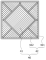
도 2는 본 발명의 일 실시예에 따른 작업공간부를 개략적으로 나타내는 평면도이다.
도 3은 본 발명의 일 실시예에 따른 작업공간부를 개략적으로 나타내는 측면도이다.
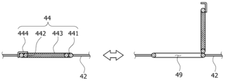
도 4는 본 발명의 일 실시예에 따른 작업도어부를 개략적으로 나타내는 도면이다.
도 5는 본 발명의 일 실시예에 따른 사다리부를 개략적으로 나타내는 평면도이다.
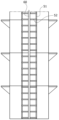
도 6은 본 발명의 일 실시예에 따른 사다리부를 개략적으로 나타내는 측면도이다.1 is a diagram schematically showing a modular steel tower according to an embodiment of the present invention.
Figure 2 is a plan view schematically showing a work space unit according to an embodiment of the present invention.
Figure 3 is a side view schematically showing a work space unit according to an embodiment of the present invention.
Figure 4 is a diagram schematically showing a work door portion according to an embodiment of the present invention.
Figure 5 is a plan view schematically showing a ladder portion according to an embodiment of the present invention.
Figure 6 is a side view schematically showing a ladder portion according to an embodiment of the present invention.
이하, 첨부된 도면들을 참조하여 본 발명에 따른 모듈형 철탑의 실시예를 설명한다. 이러한 과정에서 도면에 도시된 선들의 두께나 구성요소의 크기 등은 설명의 명료성과 편의상 과장되게 도시되어 있을 수 있다. 또한, 후술되는 용어들은 본 발명에서의 기능을 고려하여 정의된 용어들로서, 이는 사용자, 운용자의 의도 또는 관례에 따라 달라질 수 있다. 그러므로, 이러한 용어들에 대한 정의는 본 명세서 전반에 걸친 내용을 토대로 내려져야 할 것이다.Hereinafter, an embodiment of a modular steel tower according to the present invention will be described with reference to the attached drawings. In this process, the thickness of lines or sizes of components shown in the drawings may be exaggerated for clarity and convenience of explanation. In addition, the terms described below are terms defined in consideration of functions in the present invention, and may vary depending on the intention or custom of the user or operator. Therefore, definitions of these terms should be made based on the content throughout this specification.
도 1은 본 발명의 일 실시예에 따른 모듈형 철탑을 개략적으로 나타내는 도면이다. 도 1을 참조하면, 본 발명의 일 실시예에 따른 모듈형 철탑(1)은 베이스부(10)와, 하부조립부(20)와, 상부조립부(30)와, 작업공간부(40)를 포함한다.1 is a diagram schematically showing a modular steel tower according to an embodiment of the present invention. Referring to FIG. 1, the modular steel tower 1 according to an embodiment of the present invention includes a
베이스부(10)는 지면에 고정 설치된다. 일예로, 4개의 베이스부(10)는 굴착된 지면에 콘트리트가 타설되어 형성될 수 있다.The
하부조립부(20)는 베이스부(10)에 장착된다. 일예로, 하부조립부(20)는 각각의 베이스부(10)에 결합되는 하부지주부(21)와, 하부지주부(21)를 연결하는 하부연결부(22)를 포함할 수 있다.The
상부조립부(30)는 하부조립부(20)에 결합되고 복수개가 적층된다. 일예로, 상부조립부(30)는 크레인을 통해 하부조립부(20)에 적층되고, 하부조립부(20)와 상부조립부(30)의 조립이 완료되면, 크레인은 추가로 상부조립부(30)를 적층할 수 있다. 상부조립부(30)는 하부지지부(21)와 겹쳐져 조립되는 상부지주부(31)와, 상부지주부(31)를 연결하는 상부연결부(32)를 포함할 수 있다. 상부연결부(32)는 이격된 상부지주부(31)를 수평방향으로 연결하는 수평연결부(321)와, 이격된 상부지주부(31)를 경사방향으로 연결하는 경사연결부(322)를 포함할 수 있다. 이때, 하부연결부(22)의 일부와 상부연결부(32)의 일부는 겹쳐져 볼트 조립될 수 있다.The
작업공간부(40)는 상부조립부(30)에 장착되고, 작업자의 작업공간을 형성한다. 일예로, 작업공간부(40)는 상부조립부(30)의 상단부에 구비되고, 상부조립부(30)가 서로 적층되어 겹쳐지면 작업자는 작업공간부(40)에서 겹쳐진 상부조립부(30)를 볼트 결합할 수 있다.The
도 2는 본 발명의 일 실시예에 따른 작업공간부를 개략적으로 나타내는 평면도이고, 도 3은 본 발명의 일 실시예에 따른 작업공간부를 개략적으로 나타내는 측면도이다. 도 2와 도 3을 참조하면, 본 발명의 일 실시예에 따른 작업공간부(40)는 작업발판부(41)와 작업안전부(42)를 포함한다.Figure 2 is a plan view schematically showing a work space according to an embodiment of the present invention, and Figure 3 is a side view schematically showing a work space according to an embodiment of the present invention. Referring to FIGS. 2 and 3, the
작업발판부(41)는 상부조립부(30)의 상부에 결합되고, 작업자를 지지한다. 일예로, 작업발판부(41)는 상부지주부(31)의 상단부를 연결하는 수평연결부(321)에 결합되어 수평연결부(321)의 내부 빈 공간을 커버하는 철망이 될 수 있다. 이러한 작업발판부(41)에서 작업자는 안전하게 작업을 할 수 있다.The
작업안전부(42)는 상부조립부(30)의 상부에 결합되고, 작업자 또는 장비의 추락을 방지한다. 일예로, 작업안전부(42)는 사각형 형상을 하는 수평연결부(321)에 각각 장착되는 안전틀부(421)와, 안전틀부(421)에 장착되는 안전망부(422)를 포함할 수 있다. 안전틀부(421)는 상방으로 경사지게 배치되고, 수평연결부(321) 보다 확장된 사각형 형상을 할 수 있다. 안전망부(422)는 천으로 이루어진 그물망이 될 수 있다. 안전망부(422)는 안전틀부(421)와 수평연결부(321) 사이 공간에 배치될 수 있다. The
본 발명의 일 실시예에 따른 작업공간부는(40)는 작업지지부(43)를 더 포함할 수 있다. 작업지지부(43)는 상부조립부(30)에 결합되고, 작업안전부(42)를 지지한다. 일예로, 작업지지부(43)는 상부지주부(31) 또는 상부연결부(32)에 하단부가 결합되고, 안전틀부(421)에 상단부가 결합될 수 있다. 그 외, 작업지지부(43)는 상하로 적층되는 2개의 상부조립부(30) 중에서 상방에 배치되는 상부조립부(30)에 상단부가 결합되고, 하방에 배치되는 상부조립부(30)에 장착되는 작업안전부(42)에 하단부가 결합될 수 있다.The
도 4는 본 발명의 일 실시예에 따른 작업도어부를 개략적으로 나타내는 도면이다. 도 4를 참조하면, 본 발명의 일 실시예에 따른 작업공간부(40)는 작업도어부(44)를 더 포함할 수 있다.Figure 4 is a diagram schematically showing a work door portion according to an embodiment of the present invention. Referring to FIG. 4, the
작업도어부(44)는 작업발판부(41)에 형성되고, 작업자가 통과 가능하도록 작업발판부(41)를 개폐한다. 보다 구체적으로, 작업도어부(44)는 작업발판부(41)에 형성된 통과홀부(49)를 개폐할 수 있다. 일예로, 작업도어부(44)는 작업발판부(41)에 결합되고 통과홀부(49)를 형성하는 제1도어부(441)와, 제1도어부(441)에 회전 가능하도록 장착되고, 제1도어부(441)에 삽입 가능한 제2도어부(442)와, 제2도어부(442)의 내측에 연결되고 망 형상을 하여 작업자나 장비 추락을 방지하는 제3도어부(443)와, 제2도어부(442)에 결합되고, 제1도어부(441)에 걸려 제3도어부(443)가 통과홀부(49)를 커버하는 상태를 유지시키는 제4도어부(444)를 포함할 수 있다.The
도 5는 본 발명의 일 실시예에 따른 사다리부를 개략적으로 나타내는 평면도이고, 도 6은 본 발명의 일 실시예에 따른 사다리부를 개략적으로 나타내는 측면도이다. 도 5와 도 6을 참조하면, 본 발명의 일 실시예에 따른 모듈형 철탑(1)은 사다리부(50)를 더 포함할 수 있다.Figure 5 is a plan view schematically showing a ladder unit according to an embodiment of the present invention, and Figure 6 is a side view schematically showing the ladder unit according to an embodiment of the present invention. Referring to Figures 5 and 6, the modular steel tower 1 according to an embodiment of the present invention may further include a
사다리부(50)는 상부조립부(30)와 작업공간부(40) 중 어느 하나에 결합되고, 작업자가 밟고 상하 이동할 수 있다. 일예로, 사다리부(50)는 상부연결부(32)에 결합되고 상하로 길이를 갖는 한 쌍의 제1사다리부(51)와, 제1사다리부(51)에 양단부가 결합되어 발판이 되는 제2사다리부(52)를 포함할 수 있다. 사다리부(50)는 상부조립부(30)의 상단부에서 하단부까지 연장될 수 있다. 이로 인해, 상부조립부(30)가 적층된 경우, 각각의 상부조립부(30)에 장착된 사다리부(50)는 서로 연이어 배치되므로, 작업자는 사다리부(50)를 통해 적층된 상부조립부(30)를 이동할 수 있다. 그 외, 사다리부(50)는 제1사다리부(51)에 양단부가 결합되고 작업자를 감싸도록 구부러진 제3사다리부(53)를 더 포함할 수 있다.The
한편, 작업자가 사다리부(50)를 통해 이동 가능하도록, 작업안전부(42)의 일부에는 통과홀부(49)가 형성될 수 있으며, 통과홀부(49)를 개폐하는 작업도어부(44)는 필요에 따라 설치되거나 설치되지 않을 수 있다.Meanwhile, a pass-through
본 발명의 일 실시예에 따른 모듈형 철탑(1)은 안전레일부(60)를 더 포함할 수 있다. 안전레일부(60)는 사다리부(50)에 장착되고, 작업자와 연결되어 작업자의 추락을 방지한다. 일예로, 안전레일부(60)는 제1사다리부(51)와 상응하는 길이로 제1사다리부(51) 사이에 배치되고, 제2사다리부(52)에 결합될 수 있다. 작업자는 착용하고 있는 안전대의 고리를 안전레일부(60)에 걸어 둠으로써, 작업자가 사다리부(50)를 이용하여 승하강하는 동안 추락사고를 방지할 수 있다.The modular steel tower 1 according to an embodiment of the present invention may further include a
상기한 구성을 갖는 본 발명의 일 실시예에 따른 모듈형 철탑의 조립과정을 설명하면 다음과 같다.The assembly process of the modular steel tower according to an embodiment of the present invention having the above configuration will be described as follows.
임시가공선을 설치하기 위해 기존 철탑 근처에 베이스부(10)를 설치하고, 베이스부(10)에 하부조립부(20)를 장착한다.In order to install a temporary overhead line, a
하부조립부(20)가 장착되면, 하부조립부(20)의 상부에 상부조립부(30)를 복수개 적층하여 임시 철탑 조립 작업을 완료한다.When the
상부조립부(30)에는 작업발판부(41)가 결합되어 작업자를 지지하므로, 작업발판부(41) 내에서 작업자는 자유롭게 이동하면서 겹쳐진 상부조립부(30)를 볼트 결합시켜 상부조립부(30)를 적층시킬 수 있다. A
한편, 크레인을 통해 조립 완료된 하단 상부조립부(30) 상부에 조립이 필요한 상단 상부조립부(30)를 배치시키면, 작업자는 조립 완료된 하단 상부조립부(30)에 장착된 사다리부(50)를 타고 조립 완료된 상단 상부조립부(30)에 형성되는 작업공간부(40)에서 하단 상부조립부(30)와 상단 상부조립부(30)에 대한 조립 작업을 실시할 수 있다.Meanwhile, when the upper
본 발명의 일 실시예에 따른 모듈형 철탑(1)은 지면에 베이스부(10)를 설치하고, 베이스부(10)에 하부조립부(20)를 장착한 다음 상부조립부(30)를 적층하여 현장에서 조립함으로써, 임시 철탑을 신속하게 조립 완료하고, 작업자의 동선을 확보하여 작업자의 안전을 보장할 수 있다.The modular steel tower (1) according to an embodiment of the present invention installs the base portion (10) on the ground, mounts the lower assembly portion (20) on the base portion (10), and then stacks the upper assembly portion (30). By assembling it on site, the temporary steel tower can be assembled quickly and the safety of workers can be guaranteed by securing the movement of workers.
본 발명은 도면에 도시된 실시예를 참고로 하여 설명되었으나, 이는 예시적인 것에 불과하며, 당해 기술이 속하는 분야에서 통상의 지식을 가진 자라면 이로부터 다양한 변형 및 균등한 타 실시예가 가능하다는 점을 이해할 것이다. 따라서, 본 발명의 진정한 기술적 보호범위는 아래의 특허청구범위에 의해서 정하여져야 할 것이다.The present invention has been described with reference to the embodiments shown in the drawings, but these are merely exemplary, and those skilled in the art will recognize that various modifications and other equivalent embodiments are possible therefrom. You will understand. Therefore, the true technical protection scope of the present invention should be determined by the scope of the patent claims below.
10 : 베이스부 20 : 하부조립부
30 : 상부조립부 40 : 작업공간부
41 : 작업발판부 42 : 작업안전부
43 : 작업지지부 44 : 작업도어부
50 : 사다리부 60 : 안전레일부10: base part 20: lower assembly part
30: upper assembly part 40: work space part
41: work scaffolding part 42: work safety part
43: work support part 44: work door part
50: ladder part 60: safety rail part
Claims (5)
상기 베이스부에 장착되는 하부조립부;
상기 하부조립부에 결합되고 복수개가 적층되는 상부조립부; 및
상기 상부조립부에 장착되고, 작업자의 작업공간을 형성하는 작업공간부;를 포함하는 것을 특징으로 하는 모듈형 철탑.
A base portion fixed to the ground;
A lower assembly portion mounted on the base portion;
An upper assembly unit coupled to the lower assembly unit and stacked in plural pieces; and
A modular steel tower comprising a work space portion mounted on the upper assembly portion and forming a work space for an operator.
상기 상부조립부의 상부에 결합되고, 작업자를 지지하는 작업발판부; 및
상기 상부조립부의 상부에 결합되고, 추락을 방지하는 작업안전부;를 포함하는 것을 특징으로 하는 모듈형 철탑.
The method of claim 1, wherein the work space unit is
A work stool coupled to the upper part of the upper assembly and supporting the worker; and
A modular steel tower comprising a work safety part that is coupled to the upper part of the upper assembly and prevents falling.
상기 작업발판부에 형성되고, 작업자가 통과 가능하도록 상기 작업발판부를 개폐하는 작업도어부;를 더 포함하는 것을 특징으로 하는 모듈형 철탑.
The method of claim 2, wherein the work space unit is
A modular steel tower further comprising a work door portion formed on the work scaffold and opening and closing the work scaffold to allow workers to pass through.
상기 상부조립부와 상기 작업공간부 중 어느 하나에 결합되고, 작업자가 밟고 상하 이동할 수 있는 사다리부;를 더 포함하는 것을 특징으로 하는 모듈형 철탑.
According to clause 1,
A modular steel tower further comprising a ladder part that is coupled to one of the upper assembly part and the work space part and can be moved up and down by a worker stepping on it.
상기 사다리부에 장착되고, 작업자와 연결되어 작업자의 추락을 방지하는 안전레일부;를 더 포함하는 것을 특징으로 하는 모듈형 철탑.According to clause 4,
A modular steel tower further comprising a safety rail unit mounted on the ladder unit and connected to the worker to prevent the worker from falling.
Priority Applications (8)
| Application Number | Priority Date | Filing Date | Title |
|---|---|---|---|
| KR1020220094631A KR102704615B1 (en) | 2022-07-29 | 2022-07-29 | Modular pylon |
| KR1020240118636A KR102753685B1 (en) | 2022-07-29 | 2024-09-02 | Pylon |
| KR1020240118648A KR102768990B1 (en) | 2022-07-29 | 2024-09-02 | Pylon of module assembly type |
| KR1020240118642A KR102768991B1 (en) | 2022-07-29 | 2024-09-02 | Modular pylon |
| KR1020240119288A KR102768989B1 (en) | 2022-07-29 | 2024-09-03 | Modular pylon having work space |
| KR1020240119294A KR102768988B1 (en) | 2022-07-29 | 2024-09-03 | Modular pylon having walk plate |
| KR1020240119964A KR102759083B1 (en) | 2022-07-29 | 2024-09-04 | Modular pylon having passable walk plate |
| KR1020240120160A KR102758461B1 (en) | 2022-07-29 | 2024-09-04 | Modular pylon having work space |
Applications Claiming Priority (1)
| Application Number | Priority Date | Filing Date | Title |
|---|---|---|---|
| KR1020220094631A KR102704615B1 (en) | 2022-07-29 | 2022-07-29 | Modular pylon |
Related Child Applications (7)
| Application Number | Title | Priority Date | Filing Date |
|---|---|---|---|
| KR1020240118636A Division KR102753685B1 (en) | 2022-07-29 | 2024-09-02 | Pylon |
| KR1020240118642A Division KR102768991B1 (en) | 2022-07-29 | 2024-09-02 | Modular pylon |
| KR1020240118648A Division KR102768990B1 (en) | 2022-07-29 | 2024-09-02 | Pylon of module assembly type |
| KR1020240119288A Division KR102768989B1 (en) | 2022-07-29 | 2024-09-03 | Modular pylon having work space |
| KR1020240119294A Division KR102768988B1 (en) | 2022-07-29 | 2024-09-03 | Modular pylon having walk plate |
| KR1020240120160A Division KR102758461B1 (en) | 2022-07-29 | 2024-09-04 | Modular pylon having work space |
| KR1020240119964A Division KR102759083B1 (en) | 2022-07-29 | 2024-09-04 | Modular pylon having passable walk plate |
Publications (2)
| Publication Number | Publication Date |
|---|---|
| KR20240016632A true KR20240016632A (en) | 2024-02-06 |
| KR102704615B1 KR102704615B1 (en) | 2024-09-11 |
Family
ID=89858422
Family Applications (8)
| Application Number | Title | Priority Date | Filing Date |
|---|---|---|---|
| KR1020220094631A Active KR102704615B1 (en) | 2022-07-29 | 2022-07-29 | Modular pylon |
| KR1020240118642A Active KR102768991B1 (en) | 2022-07-29 | 2024-09-02 | Modular pylon |
| KR1020240118648A Active KR102768990B1 (en) | 2022-07-29 | 2024-09-02 | Pylon of module assembly type |
| KR1020240118636A Active KR102753685B1 (en) | 2022-07-29 | 2024-09-02 | Pylon |
| KR1020240119294A Active KR102768988B1 (en) | 2022-07-29 | 2024-09-03 | Modular pylon having walk plate |
| KR1020240119288A Active KR102768989B1 (en) | 2022-07-29 | 2024-09-03 | Modular pylon having work space |
| KR1020240119964A Active KR102759083B1 (en) | 2022-07-29 | 2024-09-04 | Modular pylon having passable walk plate |
| KR1020240120160A Active KR102758461B1 (en) | 2022-07-29 | 2024-09-04 | Modular pylon having work space |
Family Applications After (7)
| Application Number | Title | Priority Date | Filing Date |
|---|---|---|---|
| KR1020240118642A Active KR102768991B1 (en) | 2022-07-29 | 2024-09-02 | Modular pylon |
| KR1020240118648A Active KR102768990B1 (en) | 2022-07-29 | 2024-09-02 | Pylon of module assembly type |
| KR1020240118636A Active KR102753685B1 (en) | 2022-07-29 | 2024-09-02 | Pylon |
| KR1020240119294A Active KR102768988B1 (en) | 2022-07-29 | 2024-09-03 | Modular pylon having walk plate |
| KR1020240119288A Active KR102768989B1 (en) | 2022-07-29 | 2024-09-03 | Modular pylon having work space |
| KR1020240119964A Active KR102759083B1 (en) | 2022-07-29 | 2024-09-04 | Modular pylon having passable walk plate |
| KR1020240120160A Active KR102758461B1 (en) | 2022-07-29 | 2024-09-04 | Modular pylon having work space |
Country Status (1)
| Country | Link |
|---|---|
| KR (8) | KR102704615B1 (en) |
Citations (4)
| Publication number | Priority date | Publication date | Assignee | Title |
|---|---|---|---|---|
| JPH05280194A (en) * | 1992-03-31 | 1993-10-26 | Tokyo Electric Power Co Inc:The | Suspension scaffolding equipment for steel pipe mono-column steel tower |
| KR100461510B1 (en) * | 2004-06-30 | 2004-12-16 | (주)신우디엔시 | Workbench for telegraph pole |
| WO2009048955A1 (en) * | 2007-10-09 | 2009-04-16 | Willis Jeffrey O | Tower structure and method of assembling |
| KR20100002626U (en) * | 2008-08-29 | 2010-03-10 | 삼우플랜트(주) | Steel pipe holding |
-
2022
- 2022-07-29 KR KR1020220094631A patent/KR102704615B1/en active Active
-
2024
- 2024-09-02 KR KR1020240118642A patent/KR102768991B1/en active Active
- 2024-09-02 KR KR1020240118648A patent/KR102768990B1/en active Active
- 2024-09-02 KR KR1020240118636A patent/KR102753685B1/en active Active
- 2024-09-03 KR KR1020240119294A patent/KR102768988B1/en active Active
- 2024-09-03 KR KR1020240119288A patent/KR102768989B1/en active Active
- 2024-09-04 KR KR1020240119964A patent/KR102759083B1/en active Active
- 2024-09-04 KR KR1020240120160A patent/KR102758461B1/en active Active
Patent Citations (4)
| Publication number | Priority date | Publication date | Assignee | Title |
|---|---|---|---|---|
| JPH05280194A (en) * | 1992-03-31 | 1993-10-26 | Tokyo Electric Power Co Inc:The | Suspension scaffolding equipment for steel pipe mono-column steel tower |
| KR100461510B1 (en) * | 2004-06-30 | 2004-12-16 | (주)신우디엔시 | Workbench for telegraph pole |
| WO2009048955A1 (en) * | 2007-10-09 | 2009-04-16 | Willis Jeffrey O | Tower structure and method of assembling |
| KR20100002626U (en) * | 2008-08-29 | 2010-03-10 | 삼우플랜트(주) | Steel pipe holding |
Also Published As
| Publication number | Publication date |
|---|---|
| KR20240141658A (en) | 2024-09-27 |
| KR20240141657A (en) | 2024-09-27 |
| KR102768988B1 (en) | 2025-02-19 |
| KR20240136281A (en) | 2024-09-13 |
| KR20240136278A (en) | 2024-09-13 |
| KR20240136277A (en) | 2024-09-13 |
| KR20240137519A (en) | 2024-09-20 |
| KR102758461B1 (en) | 2025-01-22 |
| KR102768989B1 (en) | 2025-02-19 |
| KR20240138534A (en) | 2024-09-20 |
| KR102753685B1 (en) | 2025-01-15 |
| KR102768990B1 (en) | 2025-02-19 |
| KR102704615B1 (en) | 2024-09-11 |
| KR102768991B1 (en) | 2025-02-19 |
| KR102759083B1 (en) | 2025-01-24 |
Similar Documents
| Publication | Publication Date | Title |
|---|---|---|
| US4231148A (en) | Elevator erection method | |
| US20150292263A1 (en) | Supply Frame for a Tower; Tower with a Supply Frame and Method for Erecting a Supply Frame in the Interior of a Tower | |
| CN113719163B (en) | Cement plant storage warehouse with modular maintenance platform structure suspended inside the warehouse | |
| CN111894272A (en) | Intelligent construction platform and installation process and construction process thereof | |
| KR920701599A (en) | Building construction systems | |
| CN116181041B (en) | Building machine of multilayer quick construction | |
| JP4163177B2 (en) | Scaffolding system | |
| CN108396657A (en) | High pier bridge pier shaft reinforcing bar binding operation protective frame | |
| CN212897815U (en) | Modular maintenance platform structure and maintenance platform for cement plant storage warehouse | |
| KR102758461B1 (en) | Modular pylon having work space | |
| CN211815605U (en) | Construction device for pile column type pier tie beam and capping beam | |
| JP6438931B2 (en) | Temporary column, temporary column installation structure, and roof frame construction method | |
| JP3864189B2 (en) | Tower-like structure dismantling device and dismantling method using it | |
| CN112302320A (en) | Building stand column modularized assembly type scaffold module, system and construction method | |
| CN211369601U (en) | Protection device for construction site faces limit operation | |
| KR20220059108A (en) | A structure of a flared shieldin integrated with climbing system and the mounting method thereof | |
| CN220746666U (en) | Adjustable highway limit for height frame | |
| CN222879185U (en) | Operation platform for construction of assembled no-floor frame structure | |
| CN217453745U (en) | Shore bridge girder installation frock | |
| KR100508125B1 (en) | A safety way equipment for a tower crane and installing methods thereof | |
| CN218643209U (en) | Be used for high altitude construction pin-connected panel construction platform of column | |
| JP2997449B1 (en) | Rebar assembling work scaffold and construction method of rebar structure using this work scaffold | |
| CN213198127U (en) | Prefabricated stand prevents device that topples | |
| JP2690822B2 (en) | Steel construction method for low-rise buildings | |
| JP2019199779A (en) | Temporary frame column and method for constructing temporary scaffold using the same |
Legal Events
| Date | Code | Title | Description |
|---|---|---|---|
| PA0109 | Patent application |
Patent event code: PA01091R01D Comment text: Patent Application Patent event date: 20220729 |
|
| PA0201 | Request for examination | ||
| E902 | Notification of reason for refusal | ||
| PE0902 | Notice of grounds for rejection |
Comment text: Notification of reason for refusal Patent event date: 20231219 Patent event code: PE09021S01D |
|
| PG1501 | Laying open of application | ||
| E701 | Decision to grant or registration of patent right | ||
| PE0701 | Decision of registration |
Patent event code: PE07011S01D Comment text: Decision to Grant Registration Patent event date: 20240823 |
|
| GRNT | Written decision to grant | ||
| PR0701 | Registration of establishment |
Comment text: Registration of Establishment Patent event date: 20240904 Patent event code: PR07011E01D |
|
| PR1002 | Payment of registration fee |
Payment date: 20240905 End annual number: 3 Start annual number: 1 |
|
| PG1601 | Publication of registration |