KR20240053473A - Cleaner - Google Patents
Cleaner Download PDFInfo
- Publication number
- KR20240053473A KR20240053473A KR1020220133624A KR20220133624A KR20240053473A KR 20240053473 A KR20240053473 A KR 20240053473A KR 1020220133624 A KR1020220133624 A KR 1020220133624A KR 20220133624 A KR20220133624 A KR 20220133624A KR 20240053473 A KR20240053473 A KR 20240053473A
- Authority
- KR
- South Korea
- Prior art keywords
- diffuser
- impeller
- radiating
- axial
- main body
- Prior art date
- Legal status (The legal status is an assumption and is not a legal conclusion. Google has not performed a legal analysis and makes no representation as to the accuracy of the status listed.)
- Pending
Links
Images


Classifications
-
- A—HUMAN NECESSITIES
- A47—FURNITURE; DOMESTIC ARTICLES OR APPLIANCES; COFFEE MILLS; SPICE MILLS; SUCTION CLEANERS IN GENERAL
- A47L—DOMESTIC WASHING OR CLEANING; SUCTION CLEANERS IN GENERAL
- A47L9/00—Details or accessories of suction cleaners, e.g. mechanical means for controlling the suction or for effecting pulsating action; Storing devices specially adapted to suction cleaners or parts thereof; Carrying-vehicles specially adapted for suction cleaners
- A47L9/0081—Means for exhaust-air diffusion; Means for sound or vibration damping
-
- A—HUMAN NECESSITIES
- A47—FURNITURE; DOMESTIC ARTICLES OR APPLIANCES; COFFEE MILLS; SPICE MILLS; SUCTION CLEANERS IN GENERAL
- A47L—DOMESTIC WASHING OR CLEANING; SUCTION CLEANERS IN GENERAL
- A47L9/00—Details or accessories of suction cleaners, e.g. mechanical means for controlling the suction or for effecting pulsating action; Storing devices specially adapted to suction cleaners or parts thereof; Carrying-vehicles specially adapted for suction cleaners
- A47L9/10—Filters; Dust separators; Dust removal; Automatic exchange of filters
- A47L9/12—Dry filters
- A47L9/127—Dry filters tube- or sleeve-shaped
-
- A—HUMAN NECESSITIES
- A47—FURNITURE; DOMESTIC ARTICLES OR APPLIANCES; COFFEE MILLS; SPICE MILLS; SUCTION CLEANERS IN GENERAL
- A47L—DOMESTIC WASHING OR CLEANING; SUCTION CLEANERS IN GENERAL
- A47L9/00—Details or accessories of suction cleaners, e.g. mechanical means for controlling the suction or for effecting pulsating action; Storing devices specially adapted to suction cleaners or parts thereof; Carrying-vehicles specially adapted for suction cleaners
- A47L9/22—Mountings for motor fan assemblies
Landscapes
- Engineering & Computer Science (AREA)
- Mechanical Engineering (AREA)
- Structures Of Non-Positive Displacement Pumps (AREA)
Abstract
Description
본 개시는 디퓨저를 갖는 청소기에 관한 것이다.The present disclosure relates to a vacuum cleaner having a diffuser.
청소기는 실내의 오물(rubbish)을 제거하여 청결하게 하는 기구로서, 가정에서는 일반적으로 진공청소기가 많이 사용된다. 진공청소기는 팬모터 장치의 흡입력을 이용하여 공기를 빨아들인 후 흡입된 공기 중의 오물을 필터 등과 같은 장치로 분리해냄으로써 실내를 청결하게 한다. 이러한 진공청소기로는 캐니스터형(canister type)과 업라이트형(upright type)이 있으며, 최근에는 사용자의 조작 없이 청소 영역을 스스로 주행하며 피청소면으로부터 먼지 등의 오물을 흡입하여 청소 작업을 수행하는 로봇청소기가 대중화되고 있다.A vacuum cleaner is a device that removes indoor dirt and cleans it, and vacuum cleaners are commonly used in homes. A vacuum cleaner cleans the room by sucking in air using the suction power of a fan motor device and then separating the dirt in the sucked air with a device such as a filter. There are two types of vacuum cleaners: canister type and upright type. Recently, robot vacuum cleaners are used to perform cleaning work by automatically traveling through the cleaning area without user intervention and sucking in dust and other impurities from the surface being cleaned. is becoming popular.
청소기는 흡입력이 발생되도록 팬모터 장치를 포함할 수 있다. 팬모터 장치는 외부의 공기 및 오물을 청소기의 내부로 흡입한 후, 오물이 여과된 공기를 청소기의 외부로 배출시키도록 구성될 수 있다.The vacuum cleaner may include a fan motor device to generate suction force. The fan motor device may be configured to suck external air and dirt into the interior of the cleaner and then discharge the air with filtered dirt to the outside of the cleaner.
팬모터 장치는 임펠러와, 임펠러로부터 배출되는 공기를 확산시키기 위한 디퓨저를 포함할 수 있다. 디퓨저는 임펠러로부터 배출되는 공기를 확산시킴에 따라, 팬모터 장치의 효율을 증가시킬 수 있다. 디퓨저가 임펠러의 회전 축 방향으로 연장됨에 따라, 청소기의 길이 및/또는 무게가 증가할 수 있다.The fan motor device may include an impeller and a diffuser to diffuse air discharged from the impeller. The diffuser can increase the efficiency of the fan motor device by diffusing the air discharged from the impeller. As the diffuser extends in the direction of the impeller's rotation axis, the length and/or weight of the cleaner may increase.
본 개시의 일 측면은 길이를 감소시킬 수 있는 청소기를 제공한다.One aspect of the present disclosure provides a vacuum cleaner capable of reducing length.
본 개시의 일 측면은 무게를 감소시킬 수 있는 청소기를 제공한다.One aspect of the present disclosure provides a vacuum cleaner capable of reducing weight.
본 개시의 일 측면은 효율을 개선할 수 있는 청소기를 제공한다.One aspect of the present disclosure provides a vacuum cleaner capable of improving efficiency.
본 개시의 일 측면은 모터의 방열 효율이 증가될 수 있는 청소기를 제공한다.One aspect of the present disclosure provides a vacuum cleaner in which the heat dissipation efficiency of the motor can be increased.
본 문서에서 이루고자 하는 기술적 과제는 이상에서 언급한 기술적 과제로 제한되지 않으며, 언급되지 않은 또 다른 기술적 과제들은 아래의 기재로부터 본 발명이 속하는 기술분야에서 통상의 지식을 가진 자에게 명확하게 이해될 수 있을 것이다.The technical problem to be achieved in this document is not limited to the technical problem mentioned above, and other technical problems not mentioned can be clearly understood by those skilled in the art from the description below. There will be.
본 개시의 사상에 따른 청소기는 본체 배기구를 갖는 본체, 및 상기 본체의 내부에 흡입력을 발생시키도록 구성되는 팬모터 장치, 및 상기 팬모터 장치를 통과한 공기를 여과 가능하도록 상기 본체의 내부에 배치되는 필터를 포함한다. 상기 팬모터 장치는 흡입력을 발생시키기 위한 임펠러, 상기 임펠러에 동력을 제공하기 위한 모터, 및 상기 임펠러로부터 배출되는 공기를 상기 임펠러의 회전 축으로부터 방사 방향으로 가이드하도록 연장되는 방사 디퓨저 및 상기 방사 디퓨저를 통과한 공기를 상기 필터로 가이드하도록 연장되는 축 디퓨저를 포함하는 디퓨저 장치를 포함한다.A vacuum cleaner according to the spirit of the present disclosure includes a main body having a main body exhaust port, a fan motor device configured to generate suction force inside the main body, and a fan motor device disposed inside the main body so as to filter air passing through the fan motor device. Includes filters that are The fan motor device includes an impeller for generating suction force, a motor for providing power to the impeller, a radiating diffuser extending to guide air discharged from the impeller in a radial direction from the rotation axis of the impeller, and the radiating diffuser. and a diffuser device including an axial diffuser extending to guide passing air to the filter.
상기 방사 디퓨저는 상기 방사 디퓨저를 통과하는 공기를 확산시키기 위한 방사 블레이드를 포함할 수 있다.The radiating diffuser may include radiating blades for diffusing air passing through the radiating diffuser.
상기 축 디퓨저는 상기 축 디퓨저를 통과하는 공기를 확산시키기 위한 축 블레이드를 포함할 수 있다.The axial diffuser may include axial blades for diffusing air passing through the axial diffuser.
상기 축 디퓨저는 상기 방사 디퓨저로부터 연장되는 제1 축 디퓨저 및 상기 제1 축 디퓨저로부터 연장되는 제2 축 디퓨저를 포함할 수 있다.The axial diffuser may include a first axial diffuser extending from the radiating diffuser and a second axial diffuser extending from the first axial diffuser.
상기 제1 축 디퓨저는 상기 제1 축 디퓨저를 통과하는 공기를 확산시키기 위한 제1 축 블레이드를 포함할 수 있으며, 상기 제2 축 디퓨저는 상기 제2 축 디퓨저를 통과하는 공기를 확산시키기 위한 제2 축 블레이드를 포함할 수 있다.The first axis diffuser may include a first axis blade for diffusing air passing through the first axis diffuser, and the second axis diffuser may include a second axis blade for diffusing air passing through the second axis diffuser. It may include an axial blade.
상기 방사 디퓨저는 상기 임펠러가 공기를 배출하는 방향으로 연장되는 제1 방사 디퓨저를 포함할 수 있다.The radiating diffuser may include a first radiating diffuser extending in a direction in which the impeller discharges air.
상기 방사 디퓨저는 상기 제1 방사 디퓨저로부터 상기 임펠러의 회전 축에 수직한 방향으로 연장되는 제2 방사 디퓨저를 포함할 수 있다.The radiating diffuser may include a second radiating diffuser extending from the first radiating diffuser in a direction perpendicular to the rotation axis of the impeller.
상기 축 디퓨저는 상기 필터를 향해 공기를 배출하도록 형성될 수 있다.The axial diffuser may be configured to discharge air toward the filter.
상기 모터는 상기 임펠러의 공기를 흡입하는 일 측에 배치될 수 있다.The motor may be placed on one side of the impeller that sucks air.
상기 필터는 상기 임펠러의 회전 축에 대한 둘레 방향으로 상기 팬모터 장치를 둘러싸도록 형성될 수 있다.The filter may be formed to surround the fan motor device in a circumferential direction about the rotation axis of the impeller.
상기 디퓨저 장치는 상기 임펠러가 공기를 흡입하는 일 측을 향해 공기를 배출하도록 형성될 수 있다.The diffuser device may be configured to discharge air toward one side where the impeller sucks air.
상기 디퓨저 장치의 배출구는 상기 필터의 일 측에 인접하게 위치할 수 있으며, 상기 본체 배기구는 상기 필터의 일 측에 반대되는 타 측에 인접하게 위치할 수 있다.The outlet of the diffuser device may be located adjacent to one side of the filter, and the main body exhaust port may be located adjacent to the other side opposite to one side of the filter.
상기 필터는 상기 디퓨저 장치의 배출구로부터 상기 본체 배기구까지 연장될 수 있다.The filter may extend from the outlet of the diffuser device to the main body outlet.
상기 필터는 HEPA 필터(high efficiency particulate air filter)로 마련될 수 있다.The filter may be provided as a HEPA filter (high efficiency particulate air filter).
상기 필터는 상기 본체로부터 분리 가능하도록 마련될 수 있다.The filter may be provided to be detachable from the main body.
본 개시의 사상에 따른 청소기는 본체, 및 상기 본체의 내부에 흡입력을 발생시키도록 구성되는 팬모터 장치, 및 상기 팬모터 장치를 통과한 공기를 여과 가능하도록 상기 본체의 내부에 배치되는 필터를 포함한다. 상기 팬모터 장치는 흡입력을 발생시키기 위한 임펠러, 상기 임펠러의 공기를 흡입하는 일 측에 배치되며, 상기 임펠러에 동력을 제공하기 위한 모터, 상기 임펠러로부터 배출되는 공기를 상기 임펠러의 회전 축으로부터 방사 방향으로 가이드하도록 연장되는 방사 디퓨저 및 상기 방사 디퓨저를 통과한 공기를 상기 임펠러가 공기를 흡입하는 일 측을 향해 배출하도록 연장되는 축 디퓨저를 포함하는 디퓨저 장치를 포함한다.A vacuum cleaner according to the spirit of the present disclosure includes a main body, a fan motor device configured to generate suction force inside the main body, and a filter disposed inside the main body to filter air passing through the fan motor device. do. The fan motor device includes an impeller for generating suction force, a motor disposed on one side of the impeller to suck air, and a motor for providing power to the impeller, and a motor for moving air discharged from the impeller in a radial direction from the rotation axis of the impeller. It includes a diffuser device including a radiating diffuser extending to guide the radiating diffuser and an axial diffuser extending to discharge air passing through the radiating diffuser toward one side where the impeller intakes air.
상기 방사 디퓨저는 상기 방사 디퓨저를 통과하는 공기를 확산시키기 위한 방사 블레이드를 포함할 수 있으며, 상기 축 디퓨저는 상기 축 디퓨저를 통과하는 공기를 확산시키기 위한 축 블레이드를 포함할 수 있다.The radiating diffuser may include a radiating blade for diffusing air passing through the radiating diffuser, and the axial diffuser may include an axial blade for diffusing air passing through the axial diffuser.
상기 축 디퓨저는 상기 방사 디퓨저로부터 연장되며, 상기 제1 축 디퓨저를 통과하는 공기를 확산시키기 위한 제1 축 블레이드를 갖는 제1 축 디퓨저, 및 상기 제1 축 디퓨저로부터 연장되며, 상기 제2 축 디퓨저를 통과하는 공기를 확산시키기 위한 제2 축 블레이드를 갖는 제2 축 디퓨저를 포함할 수 있다.The axial diffuser extends from the radiating diffuser, a first axial diffuser having first axial blades for diffusing air passing through the first axial diffuser, and extending from the first axial diffuser, the second axial diffuser. It may include a second axis diffuser having second axis blades for diffusing the air passing through.
상기 방사 디퓨저는 상기 임펠러가 공기를 배출하는 방향으로 연장되는 제1 방사 디퓨저, 및 상기 제1 방사 디퓨저로부터 상기 임펠러의 회전 축에 수직한 방향으로 연장되는 제2 방사 디퓨저를 포함할 수 있다.The radiating diffuser may include a first radiating diffuser extending in a direction in which the impeller discharges air, and a second radiating diffuser extending from the first radiating diffuser in a direction perpendicular to the rotation axis of the impeller.
상기 필터는 상기 임펠러의 회전 축에 대한 둘레 방향으로 상기 팬모터 장치를 둘러싸도록 형성될 수 있다.The filter may be formed to surround the fan motor device in a circumferential direction about the rotation axis of the impeller.
본 개시의 사상에 따르면 청소기는 디퓨저가 임펠러의 회전 축으로부터 반경 방향으로 연장되는 부분을 가지므로, 임펠러의 회전 축 방향에 따른 길이가 감소될 수 있다.According to the spirit of the present disclosure, the diffuser of the vacuum cleaner has a portion extending radially from the rotation axis of the impeller, so the length along the direction of the rotation axis of the impeller can be reduced.
본 개시의 사상에 따르면 청소기는 임펠러의 회전 축 방향에 따른 길이가 감소됨에 따라, 무게가 감소될 수 있다.According to the spirit of the present disclosure, the weight of the vacuum cleaner can be reduced as the length along the rotation axis direction of the impeller is reduced.
본 개시의 사상에 따르면 청소기는 디퓨저가 임펠러의 회전 축으로부터 반경 방향으로 연장되는 부분을 가지므로, 효율이 개선될 수 있다.According to the spirit of the present disclosure, the efficiency of the vacuum cleaner can be improved because the diffuser has a portion extending radially from the rotation axis of the impeller.
본 개시의 사상에 따르면 청소기는 집진장치를 통과한 공기가 청소기의 외부로 배출되는 방향으로, 모터와, 임펠러와, 디퓨저가 순차적으로 배치됨에 따라, 상대적으로 저온의 공기가 모터를 통과할 수 있으므로, 모터의 방열 효율이 증가할 수 있다.According to the idea of the present disclosure, in the vacuum cleaner, a motor, an impeller, and a diffuser are sequentially arranged in the direction in which the air that has passed through the dust collection device is discharged to the outside of the cleaner, so that relatively low-temperature air can pass through the motor. , the heat dissipation efficiency of the motor can be increased.
본 개시의 사상에 따른 효과는 이상에서 언급한 효과로 제한되지 않으며, 언급되지 않은 또 다른 효과들은 아래의 기재로부터 본 발명이 속하는 기술분야에서 통상의 지식을 가진 자에게 명확하게 이해될 수 있을 것이다.The effects according to the spirit of the present disclosure are not limited to the effects mentioned above, and other effects not mentioned can be clearly understood by those skilled in the art from the description below. .
도 1은 일 실시예에 따른 청소기를 도시한다.
도 2는 도 1에 도시된 청소기의 일부 구성을 분해하여 도시한다.
도 3은 도 2에 도시된 청소기의 일부 구성을 도 2에서와 상이한 방향에서 도시한다.
도 4는 도 1에 표시된 A-A' 선에 따른 단면을 도시한다.
도 5는 도 4에 도시된 본체의 일부 구성을 분해하여 도시한다.
도 6은 도 5에 도시된 임펠러 커버와 디퓨저 장치가 결합된 모습을 도시한다.
도 7은 도 4에 표시된 B 부분을 확대하여 도시한다.
도 8은 일 실시예에 따른 임펠러 커버와 디퓨저 장치가 결합된 모습을 도시한다.
도 9는 도 8에 도시된 디퓨저 장치가 적용된 청소기를 도시한다.
도 10은 일 실시예에 따른 임펠러 커버와 디퓨저 장치가 결합된 모습을 도시한다.
도 11은 도 10에 도시된 디퓨저 장치가 적용된 청소기를 도시한다.
도 12는 일 실시예에 따른 임펠러 커버와 디퓨저 장치가 결합된 모습을 도시한다.
도 13은 도 12에 도시된 디퓨저 장치가 적용된 청소기를 도시한다.
도 14는 일 실시예에 따른 디퓨저 장치가 적용된 청소기를 도시한다.
도 15는 일 실시예에 따른 임펠러 커버와 디퓨저 장치가 결합된 모습을 도시한다.
도 16은 도 15에 도시된 디퓨저 장치가 적용된 청소기를 도시한다.
도 17은 일 실시예에 따른 디퓨저 장치가 적용된 청소기를 도시한다.1 shows a vacuum cleaner according to one embodiment.
FIG. 2 shows an exploded view of some components of the vacuum cleaner shown in FIG. 1.
FIG. 3 shows some configurations of the vacuum cleaner shown in FIG. 2 from a different direction than that in FIG. 2 .
Figure 4 shows a cross section along line AA' indicated in Figure 1.
Figure 5 shows an exploded view of a portion of the main body shown in Figure 4.
Figure 6 shows the impeller cover and diffuser device shown in Figure 5 combined.
Figure 7 shows an enlarged view of part B shown in Figure 4.
Figure 8 shows an impeller cover and a diffuser device combined according to one embodiment.
FIG. 9 shows a vacuum cleaner to which the diffuser device shown in FIG. 8 is applied.
Figure 10 shows an impeller cover and a diffuser device combined according to an embodiment.
FIG. 11 shows a vacuum cleaner to which the diffuser device shown in FIG. 10 is applied.
Figure 12 shows an impeller cover and a diffuser device combined according to an embodiment.
FIG. 13 shows a vacuum cleaner to which the diffuser device shown in FIG. 12 is applied.
Figure 14 shows a vacuum cleaner equipped with a diffuser device according to an embodiment.
Figure 15 shows an impeller cover and a diffuser device combined according to an embodiment.
Figure 16 shows a vacuum cleaner to which the diffuser device shown in Figure 15 is applied.
Figure 17 shows a vacuum cleaner equipped with a diffuser device according to an embodiment.
본 문서의 다양한 실시예들 및 이에 사용된 용어들은 본 문서에 기재된 기술적 특징들을 특정한 실시예들로 한정하려는 것이 아니며, 해당 실시예의 다양한 변경, 균등물, 또는 대체물을 포함하는 것으로 이해되어야 한다.The various embodiments of this document and the terms used herein are not intended to limit the technical features described in this document to specific embodiments, but should be understood to include various changes, equivalents, or replacements of the embodiments.
도면의 설명과 관련하여, 유사한 또는 관련된 구성요소에 대해서는 유사한 참조 부호가 사용될 수 있다.In connection with the description of the drawings, similar reference numbers may be used for similar or related components.
아이템에 대응하는 명사의 단수 형은 관련된 문맥상 명백하게 다르게 지시하지 않는 한, 상기 아이템 한 개 또는 복수 개를 포함할 수 있다.The singular form of a noun corresponding to an item may include one or more of the above items, unless the relevant context clearly indicates otherwise.
본 문서에서, "A 또는 B", "A 및 B 중 적어도 하나", "A 또는 B 중 적어도 하나", "A, B 또는 C", "A, B 및 C 중 적어도 하나", 및 "A, B, 또는 C 중 적어도 하나"와 같은 문구들 각각은 그 문구들 중 해당하는 문구에 함께 나열된 항목들 중 어느 하나, 또는 그들의 모든 가능한 조합을 포함할 수 있다.As used herein, “A or B”, “at least one of A and B”, “at least one of A or B”, “A, B or C”, “at least one of A, B and C”, and “A Each of phrases such as “at least one of , B, or C” may include any one of the items listed together in the corresponding phrase, or any possible combination thereof.
"및/또는"이라는 용어는 복수의 관련된 기재된 구성요소들의 조합 또는 복수의 관련된 기재된 구성요소들 중의 어느 구성요소를 포함한다.The term “and/or” includes any element of a plurality of related described elements or a combination of a plurality of related described elements.
"제1", "제2", 또는 "첫째" 또는 "둘째"와 같은 용어들은 단순히 해당 구성요소를 다른 해당 구성요소와 구분하기 위해 사용될 수 있으며, 해당 구성요소들을 다른 측면(예: 중요성 또는 순서)에서 한정하지 않는다.Terms such as "first", "second", or "first" or "second" may be used simply to distinguish one element from another, and may be used to distinguish such elements in other respects, such as importance or order) is not limited.
어떤(예: 제1) 구성요소가 다른(예: 제2) 구성요소에, "기능적으로" 또는 "통신적으로"라는 용어와 함께 또는 이런 용어 없이, "커플드" 또는 "커넥티드"라고 언급된 경우, 그것은 상기 어떤 구성요소가 상기 다른 구성요소에 직접적으로(예: 유선으로), 무선으로, 또는 제3 구성요소를 통하여 연결될 수 있다는 것을 의미한다.One (e.g. first) component is said to be "coupled" or "connected" to another (e.g. second) component, with or without the terms "functionally" or "communicatively". Where mentioned, it means that any of the components can be connected to the other components directly (e.g. wired), wirelessly, or through a third component.
"포함하다" 또는 "가지다"등의 용어는 본 문서에 기재된 특징, 숫자, 단계, 동작, 구성요소, 부품 또는 이들을 조합한 것이 존재함을 지정하려는 것이지, 하나 또는 그 이상의 다른 특징들이나 숫자, 단계, 동작, 구성요소, 부품 또는 이들을 조합한 것들의 존재 또는 부가 가능성을 미리 배제하지 않는다.Terms such as “include” or “have” are intended to designate the existence of features, numbers, steps, operations, components, parts, or combinations thereof described in this document, but do not include one or more other features, numbers, or steps. , does not exclude in advance the possibility of the existence or addition of operations, components, parts, or combinations thereof.
어떤 구성요소가 다른 구성요소와 "연결", "결합", "지지" 또는 "접촉"되어 있다고 할 때, 이는 구성요소들이 직접적으로 연결, 결합, 지지 또는 접촉되는 경우뿐 아니라, 제3 구성요소를 통하여 간접적으로 연결, 결합, 지지 또는 접촉되는 경우를 포함한다.When a component is said to be “connected,” “coupled,” “supported,” or “in contact” with another component, this means not only when the components are directly connected, coupled, supported, or in contact, but also when a third component This includes cases where it is indirectly connected, coupled, supported, or contacted through.
어떤 구성요소가 다른 구성요소 "상에" 위치하고 있다고 할 때, 이는 어떤 구성요소가 다른 구성요소에 접해 있는 경우뿐 아니라 두 구성요소 사이에 또 다른 구성요소가 존재하는 경우도 포함한다.When a component is said to be located “on” another component, this includes not only cases where a component is in contact with another component, but also cases where another component exists between the two components.
이하에서는 본 개시에 따른 실시예를 첨부된 도면을 참조하여 상세히 설명한다.Hereinafter, embodiments according to the present disclosure will be described in detail with reference to the attached drawings.
이하에서는 설명의 편의상 진공 청소기의 일종인 스틱형 청소기를 예로 설명하지만, 본 개시의 구성은 스틱형 청소기에 제한되지 않는다. 예를 들어, 본 개시의 구성은 캐니스터형 청소기 또는 로봇청소기 등에도 적용될 수 있다.Hereinafter, for convenience of explanation, a stick-type cleaner, which is a type of vacuum cleaner, will be used as an example. However, the configuration of the present disclosure is not limited to a stick-type cleaner. For example, the configuration of the present disclosure can also be applied to a canister-type vacuum cleaner or a robot vacuum cleaner.
도 1은 일 실시예에 따른 청소기를 도시한다. 도 2는 도 1에 도시된 청소기의 일부 구성을 분해하여 도시한다. 도 3은 도 2에 도시된 청소기의 일부 구성을 도 2에서와 상이한 방향에서 도시한다. 도 4는 도 1에 표시된 A-A' 선에 따른 단면을 도시한다.1 shows a vacuum cleaner according to one embodiment. FIG. 2 shows an exploded view of some components of the vacuum cleaner shown in FIG. 1. FIG. 3 shows some configurations of the vacuum cleaner shown in FIG. 2 from a different direction than that in FIG. 2 . Figure 4 shows a cross section along line A-A' indicated in Figure 1.
도 1 내지 도 4를 참조하면, 청소기(1)는 공기의 흡입력에 의해 피청소면의 먼지 등 이물질을 흡입하도록 마련되는 흡입 헤드(20) 및 흡입 헤드(20)를 통해 흡입된 이물질이 포집되도록 마련되는 본체(10)를 포함할 수 있다.Referring to FIGS. 1 to 4, the
청소기(1)는 흡입 헤드(20)와 본체(10) 사이를 연결하도록 마련되는 연결관(30)을 포함할 수 있다.The
흡입 헤드(20)는 흡입 브러시(미도시)를 포함하며, 피청소면에 밀착되어 피청소면의 공기와 이물질을 흡입할 수 있다. 흡입 헤드(20)는 연결관(30)에 회전 가능하게 결합될 수 있다.The
연결관(30)은 소정의 강성을 갖는 파이프 또는 플렉시블한 호스로 형성될 수 있다. 연결관(30)은 모터(111)를 통해 발생된 흡입력을 흡입 헤드(20)로 전달하고, 흡입 헤드(20)를 통해 흡입된 공기와 먼지 등 이물질을 본체(10)로 안내할 수 있다.The
연결관(30)은 흡입 헤드 커넥터(31)를 더 포함할 수 있다. 흡입 헤드 커넥터(31)는 흡입 헤드(20)를 본체(10)로부터 분리시키거나 본체(10)에 결합시키도록 마련될 수 있다.The
본체(10)는 피청소면에 흡입력을 발생시키도록 구성되는 팬모터 장치(100)와, 흡입된 공기에서 먼지를 분리하여 수집하도록 구성되는 집진장치(60)와, 사용자가 파지 가능하게 마련되는 핸들(40)과, 모터(111) 등 청소기(1)의 부품에 구동을 위해 필요한 전원을 공급하도록 마련되는 배터리(50)를 포함할 수 있다.The
본체(10)는 공기 및 이물질이 본체(10)의 내부로 흡입되는 본체 흡기구(11a) 및 본체(10)의 외부로 배출되는 본체 배기구(12a)를 포함할 수 있다. 본체(10)는 연결관(30)의 일 단과 연통되는 본체 흡입덕트(11)를 포함할 수 있으며, 본체 흡입덕트(11)의 양 단 중 연결관(30)의 일 단과 연결되는 일 단에 본체 흡기구(11a)가 형성될 수 있다. 흡입 헤드(20)에 의해 흡입된 공기 및 이물질은 연결관(30)을 지나, 본체 흡입덕트(11)의 본체 흡기구(11a)를 통해 본체(10)의 내부로 유입될 수 있다. 다만 이에 제한되지 않으며, 본체(10)는 본체 흡입덕트(11)와 같은 덕트 구조를 포함하지 않고 본체 흡기구(11a)와 연결관(30)이 직접 연결될 수 있다.The
본체(10)는 배기 케이스(12)를 포함할 수 있으며, 배기 케이스(12)의 외주면에는 공기가 본체(10) 외부로 배출되도록 마련되는 본체 배기구(12a)가 형성될 수 있다.The
본체(10)는 본체(10) 내부의 공기가 본체 배기구(12a)를 통해 본체(10)의 외부로 배출되기 전 공기 중 이물질을 여과할 수 있도록 필터(15)를 포함할 수 있다. 필터(15)는 헤파필터(HEPA filter, high efficiency particulate air filter) 일 수 있으나, 이에 제한되지 않는다.The
본체(10)는 조작부(17)를 포함할 수 있다. 사용자는 조작부(17)에 마련된 전원버튼 등을 조작하여 청소기(1)를 온/오프 시키거나 흡입강도를 조작할 수 있다.The
본체(10)에는 집진장치(60)가 마련될 수 있다. 집진장치(60)는 팬모터 장치(100)에 의한 본체(10)의 내부 공기의 유동 방향을 따라, 모터(111)보다 상류에 배치되어 집진장치(60)로 유입되는 공기로부터 이물질을 분리하고, 분리된 이물질을 수집하도록 구성될 수 있다.A
집진장치(60)는 공기로부터 분리된 이물질을 수집하도록 마련되는 집진 케이스(61)를 포함할 수 있다. 집진 케이스(61)는 집진장치(60)의 외관을 형성할 수 있다. 집진 케이스(61)는 내측에 공기로부터 분리된 이물질이 수집되는 집진 챔버(62)가 형성될 수 있다. 집진 챔버(62)는 제1 집진장치(제1 사이클론)(70)에 의해 분리된 이물질이 수집되는 공간으로 제1 집진 챔버(62)라고 지칭될 수 있다. 마찬가지로, 제1 집진 챔버(62)를 형성하는 집진 케이스(61)는 제1 집진 케이스(61)라고 지칭될 수 있다.The
제1 집진 케이스(61)의 일 측에는 흡입 헤드(20)로부터 제1 집진 챔버(62) 내부로 공기가 유입되는 유입구(63)가 형성될 수 있다. 유입구(63)는 본체 흡입 덕트(11)와 연통되도록 형성되며, 본체 흡기구(11a)를 통해 본체(10)의 내부에 유입된 공기는 유입구(63)를 통해 집진장치(60)의 내부로 유입될 수 있다. 유입구(63)는 제1 사이클론(70)으로 공기 및 이물질이 유입되도록 마련되는 점에서 제1 사이클론 유입구(63)라고 지칭될 수 있다.An
집진장치(60)는 본체(10)의 다른 구성으로부터 분리 가능하게 결합될 수 있다.The
집진장치(60)는 집진장치(60)를 본체(10)의 다른 구성에 연결시키는 연결 커버(66)와, 연결 커버(66)의 일 측에 마련되며 집진장치(60)를 본체(10)의 다른 구성으로부터 분리 가능하게 결합시키는 결합 버튼(67)을 포함할 수 있다. 보다 구체적으로, 도 1 내지 도 4에 도시된 바와 같이 연결 커버(66) 및 결합 버튼(67)은 배기 케이스(12)와 제1 집진 케이스(61)의 사이에 위치할 수 있다.The
결합 버튼(67)은 본체(10)의 일 측에 걸림 결합되도록 마련될 수 있다. 결합 버튼(67)이 본체(10)의 일 측에 걸림 결합되면, 집진장치(60)는 본체(10)에 장착될 수 있다.The
집진장치(60)가 본체(10)에 장착된 상태에서 사용자가 결합 버튼(67)을 가압하면, 결합 버튼(67)은 걸림 결합이 해제되도록 마련될 수 있으며, 이에 따라 집진장치(60)는 본체(10)로부터 분리될 수 있다. When the user presses the
집진장치(60)가 본체(10)의 다른 구성으로부터 분리되면, 사용자는 집진장치(60)에 수집된 이물질을 제거하거나, 집진장치(60)를 청소하거나, 집진장치(60) 내지 본체(10)의 부품들을 수리, 교체하는 등 다양한 동작을 수행할 수 있다. 다만 이에 제한되지 않으며, 집진장치(60)는 본체(10)로부터 다양한 방식으로 분리될 수 있다.When the
집진장치(60)는 제1 집진 케이스(61)에 마련되는 집진 케이스 도어(68)를 포함할 수 있다. 집진 케이스 도어(68)는 제1 집진 케이스(61)의 일 측에 마련되어, 제1 집진 챔버(62)를 개폐하도록 마련될 수 있다. 나아가, 집진 케이스 도어(68)는 제2 집진 챔버(81)를 개폐하도록 마련될 수 있다.The
집진 케이스 도어(68)는 회전축(68a)에 의해 제1 집진 케이스(61)에 회전 가능하게 마련될 수 있다. 집진 케이스 도어(68)는 도어 버튼(68b)을 포함할 수 있으며, 도어 버튼(68b)은 제1 집진 케이스(61)의 일 측에 걸림 결합되도록 마련될 수 있다. 도어 버튼(68b)이 제1 집진 케이스(61)의 일 측에 걸림 결합되면, 집진 케이스 도어(68)는 닫힌 상태를 유지할 수 있다. 집진 케이스 도어(68)가 닫힌 상태에서 사용자가 도어 버튼(68b)을 가압하면, 도어 버튼(68b)은 걸림 결합이 해제되도록 마련될 수 있으며, 이에 따라 집진 케이스 도어(68)는 개방될 수 있다.The dust
이에 따라, 사용자는 집진장치(60)를 본체(10)로부터 분리하거나, 또는 집진 케이스(61) 등 집진장치(60)의 구성을 분해하지 않더라고 제1 집진 챔버(62) 및 제2 집진 챔버(81) 내에 수집된 이물질을 용이하게 제거할 수 있다. 다만 집진 케이스 도어(68)에 대한 상기 설명은 본 개시의 사상에 따른 청소기(1)의 집진장치(60)로부터 수집된 이물질을 제거하기 위한 일 예시에 불과하며, 이에 본 개시의 사상은 제한되지 않는다.Accordingly, the user does not separate the
집진장치(60)는 제1 사이클론 유입구(63)를 통해 유입된 공기 및 이물질을 1차적으로 분리하도록 마련되는 제1 집진장치(70)와, 제1 집진장치(70)에 의해 이물질이 분리되고 배출된 공기가 유입되어 이물질을 2차적으로 분리하도록 마련되는 제2 집진장치(80)를 포함할 수 있다.The
제1 집진장치(70) 및 제2 집진장치(80)는 각각 사이클론 방식의 집진장치일 수 있다.The
사이클론 방식의 집진장치는 내부에서 공기 및 이물질이 회전 유동을 함에 따라 발생하는 원심력으로 이물질을 분리시키며, 공기가 유입되는 유입구는 나선형(helical) 입구, 접선 방향의 입구, 안내익 입구 등 공기의 회전 유동을 안내할 수 있는 구조를 갖도록 형성될 수 있다.The cyclone-type dust collector separates foreign substances by centrifugal force generated as air and foreign substances rotate inside, and the inlet through which air flows is a helical inlet, tangential inlet, guide wing inlet, etc. It can be formed to have a structure that can guide.
예를 들어, 제1 집진장치(70)는 제1 사이클론 유입구(63)를 통해 유입된 공기 및 이물질이 회전 유동할 수 있도록 안내하는 제1 사이클론 가이드(71)를 포함할 수 있다. 또한, 제2 집진장치(80)는 제1 집진장치(70)로부터 배출된 공기 및 이물질이 제2 집진장치(80) 내부로 유입되고, 이후 유입된 공기 및 이물질이 회전 유동할 수 있도록 안내하는 유입덕트를 포함할 수 있다.For example, the
제1 집진장치(70)에 의해 1차적으로 분리되는 이물질은 상대적으로 큰 크기의 이물질을 포함할 수 있다. 예를 들어 제1 집진장치(70)는 제1 사이클론 가이드(71)에 의해 공기가 유동하는 회전 반경이 상대적으로 크게 형성되도록 마련되고, 제1 집진 챔버(62) 또한 그에 대응되도록 크게 형성될 수 있다.Foreign substances primarily separated by the first
제2 집진장치(80)는 제1 집진장치(70)에 의해 충분히 분리되지 못한, 상대적으로 작은 크기의 이물질을 공기로부터 분리시킬 수 있다.The
제1 집진장치(70) 및 제2 집진장치(80)의 사이에는 사이클론 커버(90)가 배치될 수 있다. 사이클론 커버(90)는 제1 집진장치(70)로부터 배출된 공기 및 이물질이 사이클론 커버(90)를 지나 제2 집진장치(80)로 유입되도록 마련될 수 있다. 다시 말해서, 사이클론 커버(90)는 제1 집진장치(70)의 배출구이자, 제2 집진장치(80)의 유입구로서 기능할 수 있다.A
본체(10) 내부의 팬모터 장치(100)에 의해 흡입력이 발생하면 공기 및 이물질은 흡입 헤드(20)로 흡입될 수 있다. 흡입 헤드(20)로 흡입된 공기 및 먼지는 연결관(30)과 본체 흡기구(11a)를 거쳐 본체(10)의 내부로 흡입될 수 있다. 본체(10) 내부로 유입된 공기는 유입구(제1 사이클론 유입구)(63)를 거쳐 집진장치(60)로 유입될 수 있다. 집진장치(60)로 유입된 이물질은 1차적으로 제1 집진장치(70)에 의해 분리되어 제1 집진 챔버(62)에 수집될 수 있다. 제1 집진장치(70)에 의해 이물질이 분리된 공기는 사이클론 커버(90)를 통해 제1 집진장치(70)로부터 배출되어, 제2 집진장치(80)로 유입될 수 있다. 제2 집진장치(80)로 유입된 이물질은 제2 집진장치(80)에 의해 2차적으로 분리되어 제2 집진 챔버(81)에 수집될 수 있다. 제2 집진장치(80)에 의해 이물질이 분리된 공기는 팬모터 장치(100) 측으로 유동하며, 필터(15)에 의해 한번 더 여과된 후 본체 배기구(12a)를 통해 본체(10)의 외부로 배기될 수 있다.When suction force is generated by the
다만 전술한 바와 달리, 제1 집진장치(70)는 사이클론 방식의 집진장치로 구성되지 않을 수 있다. 예를 들어, 본 개시의 사상에 따른 제1 집진장치는 흡입 헤드로부터 유입된 공기에서 이물질을 1차적으로 분리시키는 집진장치로서, 예를 들어 다공성 필터를 통해 이물질을 분리시키는 방식의 집진장치 등 다양한 방식의 집진장치로 구성될 수 있다.However, unlike what was described above, the
청소기(1)는 집진장치(60)를 통과한 공기가 팬모터 장치(100)로 이동하는 동안, 공기로부터 이물질을 여과하기 위한 팬모터 필터(19)를 포함할 수 있다. 팬모터 필터(19)는 복수의 홀(hole)을 포함할 수 있다.The
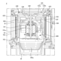
도 5는 도 4에 도시된 본체의 일부 구성을 분해하여 도시한다. 도 6은 도 5에 도시된 임펠러 커버와 디퓨저 장치가 결합된 모습을 도시한다. 도 7은 도 4에 표시된 B 부분을 확대하여 도시한다.Figure 5 shows an exploded view of a portion of the main body shown in Figure 4. Figure 6 shows the impeller cover and diffuser device shown in Figure 5 combined. Figure 7 shows an enlarged view of part B shown in Figure 4.
도 5 내지 도 7을 참조하면, 본체(10)는 본체 바디(101)를 포함할 수 있다. 본체 바디(101)의 내부에는 팬모터 장치(110)가 수용될 수 있다. 본체 바디(101)는 필터(15)로 공기를 배출하기 위한 연결구(102)를 포함할 수 있다. 연결구(102)는 본체 바디(101)의 외주면을 따라 형성될 수 있다. 연결구(102)는 팬모터 장치(100)를 통과한 공기를 필터(15)로 가이드할 수 있다.Referring to FIGS. 5 to 7 , the
본체(10)는 본체 바디(101)에 분리 가능하게 장착되는 본체 커버(106)를 포함할 수 있다. 본체 커버(106)는 배기 케이스(12)에 분리 가능하게 장착될 수 있다. 핸들(40)과, 조작부(17)는 본체 커버(106)에 마련될 수 있다. 본체 커버(106)는 본체 바디(101)의 개방된 일 측을 커버할 수 있다.The
배기 케이스(12)는 본체 커버(106)에 분리 가능하게 결합될 수 있다. 배기 케이스(12)는 필터(15)를 통과한 공기를 본체(10)의 외부로 배출하기 위한 본체 배기구(12a)를 포함할 수 있다. 본체 배기구(12a)를 통해 청소기(1)의 내부 공기는 청소기(1)의 외부로 배출될 수 있다. 일 예로, 본체 배기구(12a)는 슬릿 형상을 가질 수 있다. 일 예로, 본체 배기구(12a)는 홀(hole) 형상을 가질 수 있다. 본체 배기구(12a)는 배기 케이스(12)의 외주면을 따라 형성될 수 있다.The
필터(15)는 배기 케이스(12)의 내부에 수용될 수 있다. 필터(15)는 본체 바디(101)의 연결구(102)로부터 배출되는 공기로부터 이물질을 여과할 수 있다. 필터(15)는 팬모터 장치(100)를 통과한 공기를 여과 가능하도록 본체(10)의 내부에 배치될 수 있다. 필터(15)는 임펠러(120)의 회전 축에 대한 둘레 방향으로 팬모터 장치(100)를 둘러싸도록 형성될 수 있다.The
필터(15)는 적어도 일 부분이 연결구(102)와 마주하도록 배치될 수 있다. 필터(15)는 연결구(102)가 형성되는 본체(10)의 외주면을 따라 연장될 수 있다. 필터(15)는 연결구(102)로부터 본체 배기구(12a)까지 연장될 수 있다. 필터(15)가 연결구(102)로부터 본체 배기구(12a)까지 연장됨에 따라, 연결구(102)를 통해 배기 케이스(12)와 본체 바디(101) 사이의 공간으로 유입되는 공기는 필터(15)를 통과하며 여과된 후, 본체 배기구(12a)를 통해 배출될 수 있다. 필터(15)는 연결구(102)를 둘러싸도록 마련될 수 있다. 필터(15)는 양 측이 개방된 대략 원통 형상을 가질 수 있다.The
필터(15)는 본체(10)에 분리 가능하게 장착될 수 있다. 필터(15)는 본체 바디(101) 및/또는 본체 커버(106)에 분리 가능하게 장착될 수 있다. 사용자는 본체(10)로부터 필터(15)를 분리하여 유지 및/또는 보수를 할 수 있다.The
배기 케이스(12)는 필터(15)를 커버할 수 있다. 배기 케이스(12)는 본체 커버(106) 및/또는 본체 바디(101)에 분리 가능하게 장착될 수 있다. 배기 케이스(12)가 본체 커버(106) 및/또는 본체 바디(101)에 분리 가능하게 장착됨에 따라, 사용자는 필터(15)를 용이하게 교체할 수 있다.The
일 예로, 필터(15)는 헤파 필터(HEPA Filter, high efficiency particulate air filter)일 수 있다. 필터(15)는 집진장치(60)를 통과한 공기로부터 미세먼지와 같이 미세한 크기의 오물을 여과할 수 있다. 필터(15)를 통과하며 미세먼지가 여과된 공기는 배기 케이스(12)의 본체 배기구(12a)을 통해 청소기(1)의 외부로 배출될 수 있다.As an example, the
본체(10)의 내부에는 피청소면 상의 오물을 흡입하는데 필요한 흡입력을 발생시키는 팬모터 장치(100)가 구비될 수 있다. 팬모터 장치(100)는 본체(10)의 내부에 수용될 수 있다. 팬모터 장치(100)는 본체(10)의 내부에 흡입력을 발생시키도록 구성될 수 있다.The interior of the
팬모터 장치(100)는 모터(111)와, 모터(111)를 제어하기 위한 회로기판(112)을 포함할 수 있다. 회로기판(112)은 임펠러(120)가 결합되는 모터(111)의 일 측과 반대 측에 배치될 수 있다. 모터(111) 및/또는 회로기판(112)은 임펠러(120)가 공기를 흡입하는 일 측에 위치할 수 있다.The
모터(111)는 전자기력을 기계적인 회전력으로 전환시키는 기능을 수행할 수 있다. 위와 같은 기능을 수행하기 위해, 모터(111)는 코일이 마련되는 스테이터, 자성을 가지며 전자기력에 의해 회전이 가능한 로터 및 로터를 관통하며 회전 가능하게 마련되는 로터 샤프트(111c)를 포함할 수 있다. 본체(10)의 내부에는 모터(111)의 로터 샤프트(111c)를 통해 모터(111)에 연결되는 임펠러(120)가 마련될 수 있다.The
모터(111)는 디퓨저 장치(130)가 배치되는 임펠러(120)의 일 측과 반대되는 타 측에 배치될 수 있다. 집진장치(60)를 통과한 공기가 청소기(1)의 외부로 배출되는 방향으로, 모터(111)와, 임펠러(120)와, 디퓨저 장치(130)가 순차적으로 배치될 수 있다. 집진장치(60)를 통과한 공기가 청소기(1)의 외부로 배출되는 방향으로, 모터(111)와, 임펠러(120)와, 디퓨저 장치(130)가 순차적으로 배치됨에 따라, 상대적으로 저온의 공기가 모터(111)를 통과할 수 있으므로, 모터(111)의 방열 효율이 증가할 수 있다.The
본체(10)는 모터(111) 및/또는 회로기판(112)이 장착되는 모터 케이스(105)를 포함할 수 있다. 모터(111) 및/또는 회로기판(112)은 모터 케이스(105)의 내부에 수용될 수 있다. 모터 케이스(105)는 모터(111) 및/또는 회로기판(112)을 커버할 수 있다. 모터 케이스(105)는 바디(101)의 내부에 수용될 수 있다. 모터 케이스(105)는 본체 바디(101)에 결합될 수 있다.The
모터 케이스(105)에는 팬모터 필터(19)가 마련될 수 있다. 팬모터 필터(19)는 메쉬(mesh) 형상으로 마련되는 부분을 포함할 수 있다. 모터 케이스(105)는 팬모터 필터(19)를 통과한 공기가 팬모터 장치(100)로 유입되기 위한 팬모터 유입구(105a)를 포함할 수 있다. 팬모터 유입구(105a)는 복수의 홀(hole)을 포함할 수 있다.A
팬모터 장치(100)는 모터(111)와 결합되어 공기의 유동을 발생시키는 임펠러(120)를 포함할 수 있다. 모터(111)는 임펠러(120)에 동력을 제공할 수 있다. 임펠러(120)는 모터(111)로부터 동력을 전달받아 회전할 수 있다. 임펠러(120)는 모터 샤프트(111a)와 연결될 수 있다. 임펠러(120)는 모터(111)의 모터 샤프트(111a)를 통해 동력을 전달받을 수 있다. 임펠러(120)는 모터 샤프트(111a)에 결합된 때, 모터 샤프트(111a)와 함께 회전할 수 있다. 임펠러(120)는 흡입력을 발생시킬 수 있다.The
임펠러(120)는 허브(121)와, 허브(121)로부터 돌출되어 공기의 흐름을 형성하는 복수의 날개(122)를 포함할 수 있다.The
허브(121)는 본체(10)로 유입되는 공기가 배출되는 방향으로 갈수록 임펠러(120)의 회전 축에 수직한 단면이 커지는 형상을 가질 수 있다. 임펠러(120)는 임펠러(120)의 회전 축 방향으로 유입되는 공기를 임펠러(120)의 대략 반경 방향으로 배출하도록 마련될 수 있다.The
복수의 날개(122)는 허브(121)로부터 연장될 수 있다. 복수의 날개(122)는 임펠러(120)가 회전함에 따라, 허브(121)와 함께 기류를 형성할 수 있다. 복수의 날개(122)는 허브(121)의 공기가 유입되는 면으로부터 연장될 수 있다.A plurality of
팬모터 장치(100)는 임펠러(120)를 커버하기 위한 임펠러 커버(126)를 포함할 수 있다. 임펠러 커버(126)는 모터(111)의 적어도 일 부분을 커버하도록 마련될 수 있다. 임펠러 커버(126)는 모터(111)의 일 측에 결합될 수 있다. 임펠러 커버(126)는 디퓨저 장치(130)와 함께 임펠러(120)로부터 배출되는 공기를 가이드하는 유로를 형성할 수 있다.The
임펠러 커버(126)는 임펠러(120)를 수용할 수 있도록 임펠러(120)에 대응되는 임펠러 수용부(126a)를 포함할 수 있다. 임펠러 수용부(126a)는 공기가 흐르는 방향으로 갈수록 단면적이 커지는 형상을 가질 수 있다. 이러한 구성에 따라, 팬모터 장치(100)는 효율을 개선할 수 있다.The
팬모터 장치(100)는 디퓨저 장치(130)를 포함할 수 있다. 디퓨저장치 (130)는 임펠러(120)로부터 배출되는 공기를 가이드하도록 마련될 수 있다. 디퓨저 장치(130)는 임펠러(120)로부터 배출되는 공기를 확산시킬 수 있다. 디퓨저 장치(130)는 임펠러(120)의 회전 축에 평행한 방향으로 공기를 배출하도록 마련될 수 있다. 디퓨저 장치(130)는 대략 원판 형상을 가질 수 있다. 디퓨저 장치(130)는 임펠러(120)의 회전 축으로부터 방사 방향으로 연장될 수 있다.The
디퓨저 장치(130)는 임펠러(120)로부터 배출되는 공기를 임펠러(120)의 회전 축으로부터 방사 방향으로 가이드하도록 연장되는 방사 디퓨저(131)와, 방사 디퓨저를 통과한 공기를 필터(15)로 가이드하도록 연장되는 축 디퓨저(132)를 포함할 수 있다.The
방사 디퓨저(131)는 임펠러(120)의 회전 축으로부터 대략 방사 방향으로 연장될 수 있다. 방사 디퓨저(131)에 의해 디퓨저 장치(130)로 유입되는 공기는 임펠러(120)의 회전 축으로부터 대략 방사 방향으로 가이드될 수 있다. 방사 디퓨저(131)는 임펠러(120)의 회전 축으로부터 반경 방향으로 갈수록 임펠러(120)의 회전 축에 수직한 단면이 증가하게 형성된다.The radiating
팬모터 장치(100)는 임펠러(120)에 의한 풍량이 일정한 경우, 디퓨저 장치(130)를 통과하는 공기의 진공압에 의해 효율이 결정될 수 있다. 임펠러(120)의 회전 축으로부터 반경 방향으로 갈수록 임펠러(120)의 회전 축에 수직한 방사 디퓨저(131)의 단면이 증가함에 따라, 공기의 유속이 감소하게 된다. 방사 디퓨저(131)를 통과하는 동안 공기의 유속이 감소함에 따라, 진공압이 증가하게 된다. 방사 디퓨저(131)를 통과하는 동안 공기의 진공압이 증가함에 따라, 팬모터 장치(100)의 효율이 상승하게 된다.The efficiency of the
방사 디퓨저(131)는 임펠러(120)가 공기를 배출하는 방향으로 연장되는 제1 방사 디퓨저(131a)와, 제1 방사 디퓨저(131a)로부터 임펠러(120)의 회전 축에 대략 수직한 방향으로 연장되는 제2 방사 디퓨저(131b)를 포함할 수 있다.The radiating
디퓨저 장치(130)는 임펠러(120)가 공기를 배출하는 방향으로 연장되는 제1 방사 디퓨저(131a)를 포함함에 따라, 임펠러(120)로부터 배출되는 고속의 공기에 의한 난류의 발생을 저감시킬 수 있다. 임펠러(120)로부터 배출되는 공기에 의한 난류의 발생을 저감시킴에 따라, 디퓨저 장치(130)는 소음이 저감될 수 있다.The
임펠러(120)의 배출부에 인접한 임펠러 커버(126)의 일 부분은 임펠러(120)로부터 배출되는 공기의 방향으로 연장될 수 있다. 임펠러(120)의 배출부에 인접한 임펠러 커버(126)의 일 부분은 제1 방사 디퓨저(131a)와 함께 임펠러(120)로부터 배출되는 공기를 난류의 발생이 최소화되도록 가이드할 수 있다. 디퓨저 유입구(136)는 디퓨저 장치(130)와 임펠러 커버(126)에 의해 형성될 수 있다.A portion of the
임펠러 커버(126)는 제2 방사 디퓨저(131b)에 대응되는 부분을 포함할 수 있다. 임펠러 커버(126)는 임펠러(120)의 회전 축 방향과 대략 평행한 방향으로 연장되는 부분을 가질 수 있다. 디퓨저 배출구(137)는 디퓨저 장치(130)와 임펠러 커버(126)에 의해 형성될 수 있다. 디퓨저 배출구(137)는 제2 방사 디퓨저(131b)와 임펠러 커버(126)에 의해 형성될 수 있다.The
축 디퓨저(132)는 방사 디퓨저(131)로부터 연장될 수 있다. 축 디퓨저(132)는 제2 방사 디퓨저(131b)로부터 연장될 수 있다. 축 디퓨저(132)는 임펠러(120)의 회전 축에 대략 평행한 방향으로 연장될 수 있다. 축 디퓨저(132)는 임펠러(120)가 공기를 배출하는 방향과 반대 방향으로 공기를 가이드할 수 있다. 축 디퓨저(132)는 방사 디퓨저(131)를 통과한 공기를 임펠러(120)가 공기를 흡입하는 일 측을 향해 배출하도록 형성될 수 있다.The
디퓨저 장치(130)는 임펠러(120)가 공기를 흡입하는 일 측을 향해 공기를 배출하도록 형성될 수 있다. 디퓨저 장치(130)는 임펠러(120)를 통해 공기가 유입되는 디퓨저 유입구(136)와, 디퓨저 유입구(136)를 통해 유입되는 공기가 배출되는 디퓨저 배출구(137)가 대략 동일한 방향을 향하도록 형성될 수 있다.The
디퓨저 배출구(137)는 필터(15)의 일 측에 인접하게 위치할 수 있다. 본체 배기구(12a)는 필터(15)의 일 측에 반대되는 타 측에 인접하게 위치할 수 있다. 필터(15)는 디퓨저 배출구(137)로부터 본체 배기구(12a)까지 연장될 수 있다.The
임펠러(120)가 공기를 배출하는 방향과 반대 방향으로 축 디퓨저(132)가 공기를 배출하도록 형성됨에 따라, 본체(10)는 임펠러(120)의 회전 축 방향으로 길이가 증가하는 것을 방지할 수 있다. 일 실시예에 따른 청소기(1)는 임펠러(120)의 회전 축 방향에 따른 본체(10)의 길이를 줄일 수 있으므로, 전체적인 길이를 감소시킬 수 있으며, 전체적인 무게도 감소시킬 수 있다.As the
도 8은 일 실시예에 따른 임펠러 커버와 디퓨저 장치가 결합된 모습을 도시한다. 도 9는 도 8에 도시된 디퓨저 장치가 적용된 청소기를 도시한다.Figure 8 shows an impeller cover and a diffuser device combined according to one embodiment. FIG. 9 shows a vacuum cleaner to which the diffuser device shown in FIG. 8 is applied.
도 8 및 도 9를 참조하여, 일 실시예에 따른 청소기(2)의 팬모터 장치(200)의 디퓨저 장치(230)를 설명한다. 도 8 및 도 9에 도시된 청소기(2)의 구성을 설명함에 있어, 도 1 내지 도 7에 도시된 청소기(1)의 구성과 동일한 구성은 동일한 부재번호를 부여하고, 자세한 설명은 생략할 수 있다.With reference to FIGS. 8 and 9 , the
도 8 및 도 9를 참조하면, 일 실시예에 따른 청소기(2)의 팬모터 장치(200)는 디퓨저 장치(230)를 포함할 수 있다. 디퓨저 장치(230)는 임펠러(120)로부터 배출되는 공기를 임펠러(120)의 회전 축으로부터 방사 방향으로 가이드하도록 연장되는 방사 디퓨저(231)와, 방사 디퓨저(231)를 통과한 공기를 필터(15)로 가이드하도록 연장되는 축 디퓨저(232)를 포함할 수 있다.Referring to FIGS. 8 and 9 , the
도 9에 도시된 디퓨저 장치(230)의 방사 디퓨저(231)는 도 7에 도시된 디퓨저 장치(130)의 방사 디퓨저(131)의 제2 방사 디퓨저(131b)가 생략될 수 있다. 일 실시예에 따른 디퓨저 장치(230)의 방사 디퓨저(231)는 임펠러(120)가 공기를 배출하는 방향으로 연장되는 제1 방사 디퓨저(231a)를 포함할 수 있다. 축 디퓨저(132)는 제1 방사 디퓨저(231a)로부터 연장될 수 있다.The
일 실시예에 따른 디퓨저 장치(230)는 방사 디퓨저(231)가 임펠러(120)로부터 배출되는 공기의 방향을 따라 연장되는 제1 방사 디퓨저(231a)를 포함하며, 임펠러(120)의 회전 축 방향에 대략 수직하게 연장되는 부분이 생략되므로, 임펠러(120)로부터 배출되는 공기에 의한 난류 및/또는 소음을 더 효과적으로 저감시킬 수 있다.The
도 10은 일 실시예에 따른 임펠러 커버와 디퓨저 장치가 결합된 모습을 도시한다. 도 11은 도 10에 도시된 디퓨저 장치가 적용된 청소기를 도시한다.Figure 10 shows an impeller cover and a diffuser device combined according to an embodiment. FIG. 11 shows a vacuum cleaner to which the diffuser device shown in FIG. 10 is applied.
도 10 및 도 11을 참조하여, 일 실시예에 따른 청소기(3)의 팬모터 장치(300)의 디퓨저 장치(330)를 설명한다. 도 10 및 도 11에 도시된 청소기(3)의 구성을 설명함에 있어, 도 1 내지 도 7에 도시된 청소기(1)의 구성과 동일한 구성은 동일한 부재번호를 부여하고, 자세한 설명은 생략할 수 있다.10 and 11, the
도 10 및 도 11을 참조하면, 일 실시예에 따른 청소기(3)의 팬모터 장치(300)는 디퓨저 장치(330)를 포함할 수 있다. 디퓨저 장치(330)는 임펠러(120)로부터 배출되는 공기를 임펠러(120)의 회전 축으로부터 방사 방향으로 가이드하도록 연장되는 방사 디퓨저(331)와, 방사 디퓨저(331)를 통과한 공기를 필터(15)로 가이드하도록 연장되는 축 디퓨저(332)를 포함할 수 있다.Referring to FIGS. 10 and 11 , the
도 11에 도시된 디퓨저 장치(330)의 방사 디퓨저(331)는 도 7에 도시된 디퓨저 장치(130)의 방사 디퓨저(131)의 제2 방사 디퓨저(131b)가 생략될 수 있다. 일 실시예에 따른 디퓨저 장치(330)의 방사 디퓨저(331)는 임펠러(120)가 공기를 배출하는 방향으로 연장되는 제1 방사 디퓨저(331a)를 포함할 수 있다.The
일 실시예에 따른 디퓨저 장치(330)의 축 디퓨저(332)는 제1 방사 디퓨저(331a)로부터 필터(15)를 향해 연장될 수 있다. 디퓨저 장치(330)의 축 디퓨저(332)는 디퓨저 배출구(337)가 필터(15)를 향하도록 연장될 수 있다. 도 11에 도시된 디퓨저 장치(330)의 축 디퓨저(332)는 도 7에 도시된 디퓨저 장치(130)의 축 디퓨저(132)와 비교하였을 때, 임펠러(120)의 회전 축 방향에 대하여 경사지게 형성될 수 있다.The
일 실시예에 따른 디퓨저 장치(330)는 축 디퓨저(332)가 방사 디퓨저(331)로부터 필터(15)를 향해 연장되도록 마련되므로, 디퓨저 장치(330)로부터 배출되는 공기에 의해 필터(15)에서 발생할 수 있는 난류 및/또는 소음을 저감시킬 수 있다.The
도 12는 일 실시예에 따른 임펠러 커버와 디퓨저 장치가 결합된 모습을 도시한다. 도 13은 도 12에 도시된 디퓨저 장치가 적용된 청소기를 도시한다.Figure 12 shows an impeller cover and a diffuser device combined according to an embodiment. FIG. 13 shows a vacuum cleaner to which the diffuser device shown in FIG. 12 is applied.
도 12 및 도 13을 참조하여, 일 실시예에 따른 청소기(4)의 팬모터 장치(400)의 디퓨저 장치(430)를 설명한다. 도 12 및 도 13에 도시된 청소기(4)의 구성을 설명함에 있어, 도 1 내지 도 7에 도시된 청소기(1)의 구성과 동일한 구성은 동일한 부재번호를 부여하고, 자세한 설명은 생략할 수 있다.12 and 13, the
도 12 및 도 13을 참조하면, 일 실시예에 따른 청소기(4)의 팬모터 장치(400)는 디퓨저 장치(430)를 포함할 수 있다. 디퓨저 장치(430)는 임펠러(120)로부터 배출되는 공기를 임펠러(120)의 회전 축으로부터 방사 방향으로 가이드하도록 연장되는 방사 디퓨저(131)와, 방사 디퓨저(131)를 통과한 공기를 필터(15)로 가이드하도록 연장되는 축 디퓨저(132)를 포함할 수 있다. 방사 디퓨저(131)는 임펠러(120)가 공기를 배출하는 방향으로 연장되는 제1 방사 디퓨저(131a)와, 제1 방사 디퓨저(131a)로부터 임펠러(120)의 회전 축에 대략 수직한 방향으로 연장되는 제2 방사 디퓨저(131b)를 포함할 수 있다.Referring to FIGS. 12 and 13 , the
일 실시예에 따른 청소기(4)의 팬모터 장치(400)의 디퓨저 장치(430)는 축 디퓨저(132)의 내부에 마련되는 축 블레이드(433)를 포함할 수 있다. 축 블레이드(433)는 축 디퓨저(132)를 통과하는 공기를 확산시킬 수 있도록 형성된다. 일 실시예에 따른 청소기(4)는 축 디퓨저(132)에 축 블레이드(433)가 마련되므로, 효율이 개선될 수 있다.The
도 14는 일 실시예에 따른 디퓨저 장치가 적용된 청소기를 도시한다.Figure 14 shows a vacuum cleaner equipped with a diffuser device according to an embodiment.
도 14를 참조하여, 일 실시예에 따른 청소기(5)의 팬모터 장치(500)의 디퓨저 장치(530)를 설명한다. 도 14에 도시된 청소기(5)의 구성을 설명함에 있어, 도 1 내지 도 7에 도시된 청소기(1) 또는 도 13에 도시된 청소기(4)의 구성과 동일한 구성은 동일한 부재번호를 부여하고, 자세한 설명은 생략할 수 있다.Referring to FIG. 14, the
도 14를 참조하면, 일 실시예에 따른 청소기(5)의 팬모터 장치(500)는 디퓨저 장치(530)를 포함할 수 있다. 디퓨저 장치(530)는 임펠러(120)로부터 배출되는 공기를 임펠러(120)의 회전 축으로부터 방사 방향으로 가이드하도록 연장되는 방사 디퓨저(131)와, 방사 디퓨저(131)를 통과한 공기를 필터(15)로 가이드하도록 연장되는 축 디퓨저(132)를 포함할 수 있다. 방사 디퓨저(131)는 임펠러(120)가 공기를 배출하는 방향으로 연장되는 제1 방사 디퓨저(131a)와, 제1 방사 디퓨저(131a)로부터 임펠러(120)의 회전 축에 대략 수직한 방향으로 연장되는 제2 방사 디퓨저(131b)를 포함할 수 있다.Referring to FIG. 14 , the
일 실시예에 따른 청소기(5)의 팬모터 장치(500)의 디퓨저 장치(530)는 축 디퓨저(132)의 내부에 마련되는 축 블레이드(433)를 포함할 수 있다.The
일 실시예에 따른 청소기(5)의 팬모터 장치(500)의 디퓨저 장치(530)는 방사 디퓨저(131)의 내부에 마련되는 방사 블레이드(534)를 포함할 수 있다. 방사 블레이드(534)는 방사 디퓨저(131)의 제2 방사 디퓨저(131b)에 위치할 수 있다. 방사 블레이드(534)는 방사 디퓨저(131)를 통과하는 공기를 확산시킬 수 있도록 형성된다.The
일 실시예에 따른 청소기(5)는 축 디퓨저(132)에 축 블레이드(433)가 마련되며, 방사 디퓨저(131)에 방사 블레이드(534)가 마련되므로, 효율이 개선될 수 있다.In the
도 15는 일 실시예에 따른 임펠러 커버와 디퓨저 장치가 결합된 모습을 도시한다. 도 16은 도 15에 도시된 디퓨저 장치가 적용된 청소기를 도시한다.Figure 15 shows an impeller cover and a diffuser device combined according to an embodiment. Figure 16 shows a vacuum cleaner to which the diffuser device shown in Figure 15 is applied.
도 15 및 도 16을 참조하여, 일 실시예에 따른 청소기(6)의 팬모터 장치(600)의 디퓨저 장치(630)를 설명한다. 도 15 및 도 16에 도시된 청소기(6)의 구성을 설명함에 있어, 도 1 내지 도 7에 도시된 청소기(1) 또는 도 13에 도시된 청소기(4)의 구성과 동일한 구성은 동일한 부재번호를 부여하고, 자세한 설명은 생략할 수 있다.15 and 16, the
도 15 및 도 16을 참조하면, 일 실시예에 따른 청소기(6)의 팬모터 장치(600)는 디퓨저 장치(630)를 포함할 수 있다. 디퓨저 장치(630)는 임펠러(120)로부터 배출되는 공기를 임펠러(120)의 회전 축으로부터 방사 방향으로 가이드하도록 연장되는 방사 디퓨저(131)와, 방사 디퓨저(131)를 통과한 공기를 필터(15)로 가이드하도록 연장되는 축 디퓨저(632)를 포함할 수 있다. 방사 디퓨저(131)는 임펠러(120)가 공기를 배출하는 방향으로 연장되는 제1 방사 디퓨저(131a)와, 제1 방사 디퓨저(131a)로부터 임펠러(120)의 회전 축에 대략 수직한 방향으로 연장되는 제2 방사 디퓨저(131b)를 포함할 수 있다.Referring to FIGS. 15 and 16 , the
일 실시예에 따른 청소기(6)의 팬모터 장치(600)의 디퓨저 장치(630)의 축 디퓨저(632)는 방사 디퓨저(131)로부터 연장되는 제1 축 디퓨저(632a) 및 제1 축 디퓨저(632a)로부터 연장되는 제2 축 디퓨저(632b)를 포함할 수 있다. 제1 축 디퓨저(632a)와 제2 축 디퓨저(632b)는 임펠러(120)의 회전 축 방향과 평행한 방향으로 연장될 수 있다. 제1 축 디퓨저(632a)와 제2 축 디퓨저(632b)는 임펠러(120)의 회전 축 방향을 따라 적층될 수 있다. 제1 축 디퓨저(632a)와 제2 축 디퓨저(632b)는 임펠러(120)의 회전 축 방향을 따라 직렬로 배치될 수 있다.The
일 실시예에 따른 청소기(6)의 팬모터 장치(600)의 디퓨저 장치(430)는 축 디퓨저(632)의 내부에 마련되는 축 블레이드(633)를 포함할 수 있다. 축 블레이드(633)는 축 디퓨저(632)를 통과하는 공기를 확산시킬 수 있도록 형성된다. 축 블레이드(633)는 제1 축 디퓨저(632a)에 마련되는 제1 축 블레이드(633a) 및 제2 축 디퓨저(632b)에 마련되는 제2 축 블레이드(633b)를 포함할 수 있다. 제1 축 블레이드(633a)는 제1 축 디퓨저(632a)를 통과하는 공기를 확산시킬 수 있다. 제2 축 블레이드(633b)는 제2 축 디퓨저(632b)를 통과하는 공기를 확산시킬 수 있다.The
이러한 구성에 따라, 일 실시예에 따른 청소기(6)는 축 디퓨저(632)가 제1 축 디퓨저(632a) 및 제2 축 디퓨저(632b)를 포함하며, 제1 축 디퓨저(632a)에 제1 축 블레이드(633a)가 마련되고, 제2 축 디퓨저(632b)에 제2 축 블레이드(633b)가 마련되므로, 효율이 개선될 수 있다.According to this configuration, the
도 17은 일 실시예에 따른 디퓨저 장치가 적용된 청소기를 도시한다.Figure 17 shows a vacuum cleaner equipped with a diffuser device according to an embodiment.
도 17을 참조하여, 일 실시예에 따른 청소기(7)의 팬모터 장치(700)의 디퓨저 장치(730)를 설명한다. 도 17에 도시된 청소기(7)의 구성을 설명함에 있어, 도 1 내지 도 7에 도시된 청소기(1), 도 14에 도시된 청소기(5), 또는 도 16에 도시된 청소기(6)의 구성과 동일한 구성은 동일한 부재번호를 부여하고, 자세한 설명은 생략할 수 있다.Referring to FIG. 17, the
도 17을 참조하면, 일 실시예에 따른 청소기(7)의 팬모터 장치(700)는 디퓨저 장치(730)를 포함할 수 있다. 디퓨저 장치(730)는 임펠러(120)로부터 배출되는 공기를 임펠러(120)의 회전 축으로부터 방사 방향으로 가이드하도록 연장되는 방사 디퓨저(131)와, 방사 디퓨저(131)를 통과한 공기를 필터(15)로 가이드하도록 연장되는 축 디퓨저(632)를 포함할 수 있다. 방사 디퓨저(131)는 임펠러(120)가 공기를 배출하는 방향으로 연장되는 제1 방사 디퓨저(131a)와, 제1 방사 디퓨저(131a)로부터 임펠러(120)의 회전 축에 대략 수직한 방향으로 연장되는 제2 방사 디퓨저(131b)를 포함할 수 있다. 축 디퓨저(632)는 방사 디퓨저(131)로부터 연장되는 제1 축 디퓨저(632a) 및 제1 축 디퓨저(632a)로부터 연장되는 제2 축 디퓨저(632b)를 포함할 수 있다.Referring to FIG. 17 , the
일 실시예에 따른 청소기(7)의 팬모터 장치(700)의 디퓨저 장치(730)는 방사 디퓨저(131)의 내부에 마련되는 방사 블레이드(534)를 포함할 수 있다. 방사 블레이드(534)는 방사 디퓨저(131)를 통과하는 공기를 확산시킬 수 있도록 형성된다.The
일 실시예에 따른 청소기(7)의 팬모터 장치(700)의 디퓨저 장치(730)는 축 디퓨저(632)의 내부에 마련되는 축 블레이드(633)를 포함할 수 있다. 축 블레이드(633)는 축 디퓨저(632)를 통과하는 공기를 확산시킬 수 있도록 형성된다.The
축 블레이드(633)는 제1 축 디퓨저(632a)에 마련되는 제1 축 블레이드(633a) 및 제2 축 디퓨저(632b)에 마련되는 제2 축 블레이드(633b)를 포함할 수 있다. 제1 축 블레이드(633a)는 제1 축 디퓨저(632a)를 통과하는 공기를 확산시킬 수 있다. 제2 축 블레이드(633b)는 제2 축 디퓨저(632b)를 통과하는 공기를 확산시킬 수 있다.The
이러한 구성에 따라, 일 실시예에 따른 청소기(7)는 방사 디퓨저(131)의 내부에 방세 블레이드(534)가 마련되고, 축 디퓨저(632)가 제1 축 디퓨저(632a) 및 제2 축 디퓨저(632b)를 포함하며, 제1 축 디퓨저(632a)에 제1 축 블레이드(633a)가 마련되고, 제2 축 디퓨저(632b)에 제2 축 블레이드(633b)가 마련되므로, 효율이 개선될 수 있다.According to this configuration, the
이상에서는 특정의 실시예에 대하여 도시하고 설명하였다. 그러나, 상기한 실시예에만 한정되지 않으며, 발명이 속하는 기술분야에서 통상의 지식을 가진 자라면 이하의 청구범위에 기재된 발명의 기술적 사상의 요지를 벗어남이 없이 얼마든지 다양하게 변경 실시할 수 있을 것이다.In the above, specific embodiments are shown and described. However, it is not limited to the above-mentioned embodiments, and those skilled in the art can make various changes without departing from the gist of the technical idea of the invention as set forth in the claims below. .
1, 2, 3, 4, 5, 6, 7; 청소기
20; 흡입 헤드
30; 연결관
60; 집진장치
100, 200, 300, 400, 500, 600, 700; 팬모터 장치
111; 모터
112; 회로기판
120; 임펠러
126; 임펠러 커버
130, 230, 330, 430, 530, 630, 730; 디퓨저 장치
131, 231, 331; 방사 디퓨저
132, 332, 632; 축 디퓨저
136; 디퓨저 유입구
137; 디퓨저 배출구
433, 633; 축 블레이드
534; 방사 블레이드1, 2, 3, 4, 5, 6, 7; vacuum cleaner
20; suction head
30; connector
60; dust collection device
100, 200, 300, 400, 500, 600, 700; fan motor device
111; motor
112; circuit board
120; impeller
126; impeller cover
130, 230, 330, 430, 530, 630, 730; diffuser device
131, 231, 331; radiant diffuser
132, 332, 632; axial diffuser
136; diffuser inlet
137; diffuser outlet
433, 633; axis blade
534; radiating blade
Claims (20)
상기 본체의 내부에 흡입력을 발생시키도록 구성되는 팬모터 장치; 및
상기 팬모터 장치를 통과한 공기를 여과 가능하도록 상기 본체의 내부에 배치되는 필터;를 포함하며,
상기 팬모터 장치는,
흡입력을 발생시키기 위한 임펠러;
상기 임펠러에 동력을 제공하기 위한 모터; 및
상기 임펠러로부터 배출되는 공기를 상기 임펠러의 회전 축으로부터 방사 방향으로 가이드하도록 연장되는 방사 디퓨저 및 상기 방사 디퓨저를 통과한 공기를 상기 필터로 가이드하도록 연장되는 축 디퓨저를 포함하는 디퓨저 장치;를 포함하는 청소기.a body having a body exhaust port; and
a fan motor device configured to generate suction force inside the main body; and
It includes a filter disposed inside the main body to filter the air passing through the fan motor device,
The fan motor device,
Impeller for generating suction force;
a motor to provide power to the impeller; and
A diffuser device including a radiating diffuser extending to guide air discharged from the impeller in a radial direction from the rotation axis of the impeller and an axial diffuser extending to guide air passing through the radiating diffuser to the filter. A cleaner comprising a. .
상기 방사 디퓨저는 상기 방사 디퓨저를 통과하는 공기를 확산시키기 위한 방사 블레이드를 포함하는 청소기.According to paragraph 1,
The radiating diffuser is a cleaner including radiating blades for diffusing air passing through the radiating diffuser.
상기 축 디퓨저는 상기 축 디퓨저를 통과하는 공기를 확산시키기 위한 축 블레이드를 포함하는 청소기.According to paragraph 1,
The axial diffuser is a cleaner including axial blades for diffusing air passing through the axial diffuser.
상기 축 디퓨저는 상기 방사 디퓨저로부터 연장되는 제1 축 디퓨저 및 상기 제1 축 디퓨저로부터 연장되는 제2 축 디퓨저를 포함하는 청소기.According to paragraph 1,
The axial diffuser is a cleaner including a first axial diffuser extending from the radiating diffuser and a second axial diffuser extending from the first axial diffuser.
상기 제1 축 디퓨저는 상기 제1 축 디퓨저를 통과하는 공기를 확산시키기 위한 제1 축 블레이드를 포함하며,
상기 제2 축 디퓨저는 상기 제2 축 디퓨저를 통과하는 공기를 확산시키기 위한 제2 축 블레이드를 포함하는 청소기.According to clause 4,
The first axis diffuser includes a first axis blade for diffusing air passing through the first axis diffuser,
The second axis diffuser is a cleaner including a second axis blade for diffusing air passing through the second axis diffuser.
상기 방사 디퓨저는 상기 임펠러가 공기를 배출하는 방향으로 연장되는 제1 방사 디퓨저를 포함하는 청소기.According to paragraph 1,
The radiating diffuser is a cleaner including a first radiating diffuser extending in a direction in which the impeller discharges air.
상기 방사 디퓨저는 상기 제1 방사 디퓨저로부터 상기 임펠러의 회전 축에 수직한 방향으로 연장되는 제2 방사 디퓨저를 포함하는 청소기.According to clause 6,
The radiating diffuser is a cleaner including a second radiating diffuser extending from the first radiating diffuser in a direction perpendicular to the rotation axis of the impeller.
상기 축 디퓨저는 상기 필터를 향해 공기를 배출하도록 형성되는 청소기.According to paragraph 1,
The axial diffuser is configured to discharge air toward the filter.
상기 모터는 상기 임펠러의 공기를 흡입하는 일 측에 배치되는 청소기.According to paragraph 1,
A cleaner where the motor is disposed on one side of the impeller that sucks air.
상기 필터는 상기 임펠러의 회전 축에 대한 둘레 방향으로 상기 팬모터 장치를 둘러싸도록 형성되는 청소기.According to paragraph 1,
The filter is a cleaner formed to surround the fan motor device in a circumferential direction about the rotation axis of the impeller.
상기 디퓨저 장치는 상기 임펠러가 공기를 흡입하는 일 측을 향해 공기를 배출하도록 형성되는 청소기.According to paragraph 1,
The diffuser device is configured to discharge air toward one side where the impeller sucks air.
상기 디퓨저 장치의 배출구는 상기 필터의 일 측에 인접하게 위치하며,
상기 본체 배기구는 상기 필터의 일 측에 반대되는 타 측에 인접하게 위치하는 청소기.According to paragraph 1,
The outlet of the diffuser device is located adjacent to one side of the filter,
The main body exhaust port is located adjacent to the other side opposite to one side of the filter.
상기 필터는 상기 디퓨저 장치의 배출구로부터 상기 본체 배기구까지 연장되는 청소기.According to paragraph 1,
The filter extends from the outlet of the diffuser device to the main body outlet.
상기 필터는 HEPA 필터(high efficiency particulate air filter)로 마련되는 청소기.According to paragraph 1,
The filter is a vacuum cleaner provided with a HEPA filter (high efficiency particulate air filter).
상기 필터는 상기 본체로부터 분리 가능하도록 마련되는 청소기.According to paragraph 1,
A vacuum cleaner wherein the filter is detachable from the main body.
상기 본체의 내부에 흡입력을 발생시키도록 구성되는 팬모터 장치; 및
상기 팬모터 장치를 통과한 공기를 여과 가능하도록 상기 본체의 내부에 배치되는 필터;를 포함하며,
상기 팬모터 장치는,
흡입력을 발생시키기 위한 임펠러;
상기 임펠러의 공기를 흡입하는 일 측에 배치되며, 상기 임펠러에 동력을 제공하기 위한 모터; 및
상기 임펠러로부터 배출되는 공기를 상기 임펠러의 회전 축으로부터 방사 방향으로 가이드하도록 연장되는 방사 디퓨저 및 상기 방사 디퓨저를 통과한 공기를 상기 임펠러가 공기를 흡입하는 일 측을 향해 배출하도록 연장되는 축 디퓨저를 포함하는 디퓨저 장치;를 포함하는 청소기.main body; and
a fan motor device configured to generate suction force inside the main body; and
It includes a filter disposed inside the main body to filter the air passing through the fan motor device,
The fan motor device,
Impeller for generating suction force;
a motor disposed on one side of the impeller that sucks air and providing power to the impeller; and
It includes a radial diffuser extending to guide the air discharged from the impeller in a radial direction from the rotation axis of the impeller, and an axial diffuser extending to discharge the air passing through the radiating diffuser toward one side where the impeller intakes air. A vacuum cleaner containing a diffuser device.
상기 방사 디퓨저는 상기 방사 디퓨저를 통과하는 공기를 확산시키기 위한 방사 블레이드를 포함하며,
상기 축 디퓨저는 상기 축 디퓨저를 통과하는 공기를 확산시키기 위한 축 블레이드를 포함하는 청소기.According to clause 16,
The radiating diffuser includes radiating blades for diffusing air passing through the radiating diffuser,
The axial diffuser is a cleaner including axial blades for diffusing air passing through the axial diffuser.
상기 축 디퓨저는,
상기 방사 디퓨저로부터 연장되는 제1 축 디퓨저로서, 상기 제1 축 디퓨저를 통과하는 공기를 확산시키기 위한 제1 축 블레이드를 갖는 제1 축 디퓨저; 및
상기 제1 축 디퓨저로부터 연장되는 제2 축 디퓨저로서, 상기 제2 축 디퓨저를 통과하는 공기를 확산시키기 위한 제2 축 블레이드를 갖는 제2 축 디퓨저;를 포함하는 청소기.According to clause 16,
The axial diffuser,
a first axial diffuser extending from the radiating diffuser, the first axial diffuser having first axial blades for diffusing air passing through the first axial diffuser; and
A second axis diffuser extending from the first axis diffuser, the second axis diffuser having second axis blades for diffusing air passing through the second axis diffuser.
상기 방사 디퓨저는,
상기 임펠러가 공기를 배출하는 방향으로 연장되는 제1 방사 디퓨저; 및
상기 제1 방사 디퓨저로부터 상기 임펠러의 회전 축에 수직한 방향으로 연장되는 제2 방사 디퓨저;를 포함하는 청소기.According to clause 16,
The radiating diffuser,
a first radiating diffuser extending in a direction in which the impeller discharges air; and
A second radiating diffuser extending from the first radiating diffuser in a direction perpendicular to the rotation axis of the impeller.
상기 필터는 상기 임펠러의 회전 축에 대한 둘레 방향으로 상기 팬모터 장치를 둘러싸도록 형성되는 청소기.According to clause 16,
The filter is a cleaner formed to surround the fan motor device in a circumferential direction about the rotation axis of the impeller.
Priority Applications (5)
| Application Number | Priority Date | Filing Date | Title |
|---|---|---|---|
| KR1020220133624A KR20240053473A (en) | 2022-10-17 | 2022-10-17 | Cleaner |
| EP23879934.0A EP4509026A4 (en) | 2022-10-17 | 2023-07-04 | CLEANER |
| CN202380040504.3A CN119255737A (en) | 2022-10-17 | 2023-07-04 | Cleaner |
| PCT/KR2023/009405 WO2024085349A1 (en) | 2022-10-17 | 2023-07-04 | Cleaner |
| US18/236,017 US20240122420A1 (en) | 2022-10-17 | 2023-08-21 | Cleaner |
Applications Claiming Priority (1)
| Application Number | Priority Date | Filing Date | Title |
|---|---|---|---|
| KR1020220133624A KR20240053473A (en) | 2022-10-17 | 2022-10-17 | Cleaner |
Publications (1)
| Publication Number | Publication Date |
|---|---|
| KR20240053473A true KR20240053473A (en) | 2024-04-24 |
Family
ID=90737977
Family Applications (1)
| Application Number | Title | Priority Date | Filing Date |
|---|---|---|---|
| KR1020220133624A Pending KR20240053473A (en) | 2022-10-17 | 2022-10-17 | Cleaner |
Country Status (2)
| Country | Link |
|---|---|
| KR (1) | KR20240053473A (en) |
| WO (1) | WO2024085349A1 (en) |
Family Cites Families (6)
| Publication number | Priority date | Publication date | Assignee | Title |
|---|---|---|---|---|
| KR20090026919A (en) * | 2007-09-11 | 2009-03-16 | 엘지전자 주식회사 | Fan motor of vacuum cleaner |
| KR101943963B1 (en) * | 2017-06-30 | 2019-01-30 | 엘지전자 주식회사 | A Fan Motor |
| US11131311B2 (en) * | 2017-10-13 | 2021-09-28 | Ametek, Inc. | Motor-fan assembly with improved airflow and noise reduction properties |
| GB2586844B (en) * | 2019-09-05 | 2021-11-24 | Dyson Technology Ltd | A compressor |
| KR20220045717A (en) * | 2020-10-06 | 2022-04-13 | 삼성전자주식회사 | Cleaning system and docking device having the same |
| KR20220111968A (en) * | 2021-02-03 | 2022-08-10 | 삼성전자주식회사 | Vacuum Cleaner |
-
2022
- 2022-10-17 KR KR1020220133624A patent/KR20240053473A/en active Pending
-
2023
- 2023-07-04 WO PCT/KR2023/009405 patent/WO2024085349A1/en not_active Ceased
Also Published As
| Publication number | Publication date |
|---|---|
| WO2024085349A1 (en) | 2024-04-25 |
Similar Documents
| Publication | Publication Date | Title |
|---|---|---|
| US20240215777A1 (en) | Cleaner | |
| CN102878115B (en) | Chip purges and/or aspirator | |
| US8667638B2 (en) | Robot cleaner | |
| JP4964314B2 (en) | Silencer | |
| CN1277502C (en) | Cyclone dust collector for vacuum cleaner | |
| EP3840624B1 (en) | Sound reducing vacuum cleaner | |
| US20120186036A1 (en) | Diffuser for a vacuum cleaner motor-fan assembly | |
| CN110840326B (en) | Dust collection device and dust collection equipment | |
| US12059122B2 (en) | Dust collector and cleaner having the same | |
| KR100560327B1 (en) | Vacuum cleaner | |
| CN211484334U (en) | Dust suction device and dust suction equipment | |
| EP4509026A1 (en) | Cleaner | |
| KR20240053473A (en) | Cleaner | |
| CN101732001A (en) | Dust collecting barrel of suction cleaner | |
| KR20240104971A (en) | Cleaner | |
| JP2010279910A (en) | Apparatus for removing oil mist | |
| KR20240000978A (en) | Cleaner | |
| JP4625722B2 (en) | Electric blower and vacuum cleaner equipped with the same | |
| KR20240045905A (en) | Dust collector and cleaner having the same | |
| KR100445651B1 (en) | Cyclone type vacuum cleaner | |
| KR20230015566A (en) | Dust collector and cleaner having the same | |
| US20250185862A1 (en) | Cleaner | |
| CN222565689U (en) | A double dust chamber cyclone dust blocking handheld vacuum cleaner | |
| KR20230114510A (en) | Dust collector and cleaner having the same | |
| KR20250088256A (en) | Cleaner |
Legal Events
| Date | Code | Title | Description |
|---|---|---|---|
| PA0109 | Patent application |
Patent event code: PA01091R01D Comment text: Patent Application Patent event date: 20221017 |
|
| PG1501 | Laying open of application |