KR20240077246A - Battery pack - Google Patents
Battery pack Download PDFInfo
- Publication number
- KR20240077246A KR20240077246A KR1020220159545A KR20220159545A KR20240077246A KR 20240077246 A KR20240077246 A KR 20240077246A KR 1020220159545 A KR1020220159545 A KR 1020220159545A KR 20220159545 A KR20220159545 A KR 20220159545A KR 20240077246 A KR20240077246 A KR 20240077246A
- Authority
- KR
- South Korea
- Prior art keywords
- battery
- inclined surface
- battery pack
- battery module
- support frame
- Prior art date
- Legal status (The legal status is an assumption and is not a legal conclusion. Google has not performed a legal analysis and makes no representation as to the accuracy of the status listed.)
- Pending
Links
Images




Classifications
-
- H—ELECTRICITY
- H01—ELECTRIC ELEMENTS
- H01M—PROCESSES OR MEANS, e.g. BATTERIES, FOR THE DIRECT CONVERSION OF CHEMICAL ENERGY INTO ELECTRICAL ENERGY
- H01M50/00—Constructional details or processes of manufacture of the non-active parts of electrochemical cells other than fuel cells, e.g. hybrid cells
- H01M50/20—Mountings; Secondary casings or frames; Racks, modules or packs; Suspension devices; Shock absorbers; Transport or carrying devices; Holders
- H01M50/262—Mountings; Secondary casings or frames; Racks, modules or packs; Suspension devices; Shock absorbers; Transport or carrying devices; Holders with fastening means, e.g. locks
- H01M50/264—Mountings; Secondary casings or frames; Racks, modules or packs; Suspension devices; Shock absorbers; Transport or carrying devices; Holders with fastening means, e.g. locks for cells or batteries, e.g. straps, tie rods or peripheral frames
-
- H—ELECTRICITY
- H01—ELECTRIC ELEMENTS
- H01M—PROCESSES OR MEANS, e.g. BATTERIES, FOR THE DIRECT CONVERSION OF CHEMICAL ENERGY INTO ELECTRICAL ENERGY
- H01M50/00—Constructional details or processes of manufacture of the non-active parts of electrochemical cells other than fuel cells, e.g. hybrid cells
- H01M50/20—Mountings; Secondary casings or frames; Racks, modules or packs; Suspension devices; Shock absorbers; Transport or carrying devices; Holders
- H01M50/204—Racks, modules or packs for multiple batteries or multiple cells
- H01M50/207—Racks, modules or packs for multiple batteries or multiple cells characterised by their shape
- H01M50/209—Racks, modules or packs for multiple batteries or multiple cells characterised by their shape adapted for prismatic or rectangular cells
-
- H—ELECTRICITY
- H01—ELECTRIC ELEMENTS
- H01M—PROCESSES OR MEANS, e.g. BATTERIES, FOR THE DIRECT CONVERSION OF CHEMICAL ENERGY INTO ELECTRICAL ENERGY
- H01M50/00—Constructional details or processes of manufacture of the non-active parts of electrochemical cells other than fuel cells, e.g. hybrid cells
- H01M50/20—Mountings; Secondary casings or frames; Racks, modules or packs; Suspension devices; Shock absorbers; Transport or carrying devices; Holders
- H01M50/258—Modular batteries; Casings provided with means for assembling
-
- H—ELECTRICITY
- H01—ELECTRIC ELEMENTS
- H01M—PROCESSES OR MEANS, e.g. BATTERIES, FOR THE DIRECT CONVERSION OF CHEMICAL ENERGY INTO ELECTRICAL ENERGY
- H01M50/00—Constructional details or processes of manufacture of the non-active parts of electrochemical cells other than fuel cells, e.g. hybrid cells
- H01M50/20—Mountings; Secondary casings or frames; Racks, modules or packs; Suspension devices; Shock absorbers; Transport or carrying devices; Holders
- H01M50/204—Racks, modules or packs for multiple batteries or multiple cells
-
- H—ELECTRICITY
- H01—ELECTRIC ELEMENTS
- H01M—PROCESSES OR MEANS, e.g. BATTERIES, FOR THE DIRECT CONVERSION OF CHEMICAL ENERGY INTO ELECTRICAL ENERGY
- H01M50/00—Constructional details or processes of manufacture of the non-active parts of electrochemical cells other than fuel cells, e.g. hybrid cells
- H01M50/20—Mountings; Secondary casings or frames; Racks, modules or packs; Suspension devices; Shock absorbers; Transport or carrying devices; Holders
- H01M50/204—Racks, modules or packs for multiple batteries or multiple cells
- H01M50/207—Racks, modules or packs for multiple batteries or multiple cells characterised by their shape
- H01M50/211—Racks, modules or packs for multiple batteries or multiple cells characterised by their shape adapted for pouch cells
-
- H—ELECTRICITY
- H01—ELECTRIC ELEMENTS
- H01M—PROCESSES OR MEANS, e.g. BATTERIES, FOR THE DIRECT CONVERSION OF CHEMICAL ENERGY INTO ELECTRICAL ENERGY
- H01M50/00—Constructional details or processes of manufacture of the non-active parts of electrochemical cells other than fuel cells, e.g. hybrid cells
- H01M50/20—Mountings; Secondary casings or frames; Racks, modules or packs; Suspension devices; Shock absorbers; Transport or carrying devices; Holders
- H01M50/233—Mountings; Secondary casings or frames; Racks, modules or packs; Suspension devices; Shock absorbers; Transport or carrying devices; Holders characterised by physical properties of casings or racks, e.g. dimensions
- H01M50/242—Mountings; Secondary casings or frames; Racks, modules or packs; Suspension devices; Shock absorbers; Transport or carrying devices; Holders characterised by physical properties of casings or racks, e.g. dimensions adapted for protecting batteries against vibrations, collision impact or swelling
-
- H—ELECTRICITY
- H01—ELECTRIC ELEMENTS
- H01M—PROCESSES OR MEANS, e.g. BATTERIES, FOR THE DIRECT CONVERSION OF CHEMICAL ENERGY INTO ELECTRICAL ENERGY
- H01M50/00—Constructional details or processes of manufacture of the non-active parts of electrochemical cells other than fuel cells, e.g. hybrid cells
- H01M50/20—Mountings; Secondary casings or frames; Racks, modules or packs; Suspension devices; Shock absorbers; Transport or carrying devices; Holders
- H01M50/244—Secondary casings; Racks; Suspension devices; Carrying devices; Holders characterised by their mounting method
-
- H—ELECTRICITY
- H01—ELECTRIC ELEMENTS
- H01M—PROCESSES OR MEANS, e.g. BATTERIES, FOR THE DIRECT CONVERSION OF CHEMICAL ENERGY INTO ELECTRICAL ENERGY
- H01M50/00—Constructional details or processes of manufacture of the non-active parts of electrochemical cells other than fuel cells, e.g. hybrid cells
- H01M50/20—Mountings; Secondary casings or frames; Racks, modules or packs; Suspension devices; Shock absorbers; Transport or carrying devices; Holders
- H01M50/262—Mountings; Secondary casings or frames; Racks, modules or packs; Suspension devices; Shock absorbers; Transport or carrying devices; Holders with fastening means, e.g. locks
-
- H—ELECTRICITY
- H01—ELECTRIC ELEMENTS
- H01M—PROCESSES OR MEANS, e.g. BATTERIES, FOR THE DIRECT CONVERSION OF CHEMICAL ENERGY INTO ELECTRICAL ENERGY
- H01M50/00—Constructional details or processes of manufacture of the non-active parts of electrochemical cells other than fuel cells, e.g. hybrid cells
- H01M50/20—Mountings; Secondary casings or frames; Racks, modules or packs; Suspension devices; Shock absorbers; Transport or carrying devices; Holders
- H01M50/271—Lids or covers for the racks or secondary casings
-
- H—ELECTRICITY
- H01—ELECTRIC ELEMENTS
- H01M—PROCESSES OR MEANS, e.g. BATTERIES, FOR THE DIRECT CONVERSION OF CHEMICAL ENERGY INTO ELECTRICAL ENERGY
- H01M50/00—Constructional details or processes of manufacture of the non-active parts of electrochemical cells other than fuel cells, e.g. hybrid cells
- H01M50/20—Mountings; Secondary casings or frames; Racks, modules or packs; Suspension devices; Shock absorbers; Transport or carrying devices; Holders
- H01M50/289—Mountings; Secondary casings or frames; Racks, modules or packs; Suspension devices; Shock absorbers; Transport or carrying devices; Holders characterised by spacing elements or positioning means within frames, racks or packs
-
- H—ELECTRICITY
- H01—ELECTRIC ELEMENTS
- H01M—PROCESSES OR MEANS, e.g. BATTERIES, FOR THE DIRECT CONVERSION OF CHEMICAL ENERGY INTO ELECTRICAL ENERGY
- H01M50/00—Constructional details or processes of manufacture of the non-active parts of electrochemical cells other than fuel cells, e.g. hybrid cells
- H01M50/50—Current conducting connections for cells or batteries
- H01M50/502—Interconnectors for connecting terminals of adjacent batteries; Interconnectors for connecting cells outside a battery casing
- H01M50/507—Interconnectors for connecting terminals of adjacent batteries; Interconnectors for connecting cells outside a battery casing comprising an arrangement of two or more busbars within a container structure, e.g. busbar modules
-
- H—ELECTRICITY
- H01—ELECTRIC ELEMENTS
- H01M—PROCESSES OR MEANS, e.g. BATTERIES, FOR THE DIRECT CONVERSION OF CHEMICAL ENERGY INTO ELECTRICAL ENERGY
- H01M2220/00—Batteries for particular applications
- H01M2220/20—Batteries in motive systems, e.g. vehicle, ship, plane
-
- Y—GENERAL TAGGING OF NEW TECHNOLOGICAL DEVELOPMENTS; GENERAL TAGGING OF CROSS-SECTIONAL TECHNOLOGIES SPANNING OVER SEVERAL SECTIONS OF THE IPC; TECHNICAL SUBJECTS COVERED BY FORMER USPC CROSS-REFERENCE ART COLLECTIONS [XRACs] AND DIGESTS
- Y02—TECHNOLOGIES OR APPLICATIONS FOR MITIGATION OR ADAPTATION AGAINST CLIMATE CHANGE
- Y02E—REDUCTION OF GREENHOUSE GAS [GHG] EMISSIONS, RELATED TO ENERGY GENERATION, TRANSMISSION OR DISTRIBUTION
- Y02E60/00—Enabling technologies; Technologies with a potential or indirect contribution to GHG emissions mitigation
- Y02E60/10—Energy storage using batteries
Landscapes
- Chemical & Material Sciences (AREA)
- Chemical Kinetics & Catalysis (AREA)
- Electrochemistry (AREA)
- General Chemical & Material Sciences (AREA)
- Battery Mounting, Suspending (AREA)
Abstract
Description
본 발명은 배터리 팩에 관한 것이다.The present invention relates to a battery pack.
이차전지(배터리 셀)는 일차전지와 달리 충방전이 가능하다는 편리성이 있어, 각종 모바일 기기 및 전기 자동차 등의 동력원으로 많은 주목을 받고 있다. 배터리 모듈은 이러한 배터리 셀을 복수 개 연결하여 모듈화한 것이며, 배터리 팩은 배터리 모듈 및/또는 배터리 셀을 다수 개 연결하여 대용량의 에너지 저장 장치로 구성한 것이다.Unlike primary batteries, secondary batteries (battery cells) are convenient in that they can be charged and discharged, and are receiving a lot of attention as a power source for various mobile devices and electric vehicles. A battery module is modularized by connecting a plurality of these battery cells, and a battery pack is configured as a large-capacity energy storage device by connecting a plurality of battery modules and/or battery cells.
이차전지가 충방전을 거듭함에 따라, 이차전지의 내부에서 가스가 발생되어 폭 방향으로 팽창하는 현상이 발생될 수 있다. 이차전지를 다수 포함하는 배터리 모듈 및 배터리 팩에 있어서, 이와 같은 이차전지의 폭 방향의 변형은 배터리 모듈 또는 배터리 팩의 전기적 성능을 저하시키고, 배터리 모듈의 외형을 야기할 우려가 있다.As the secondary battery continues to charge and discharge, gas may be generated inside the secondary battery and expand in the width direction. In battery modules and battery packs containing multiple secondary batteries, such deformation in the width direction of the secondary batteries may deteriorate the electrical performance of the battery module or battery pack and cause the external appearance of the battery module to change.
한편, 배터리 모듈 및 배터리 팩에 요구되는 에너지 용량이 점차 증가됨에 따라, 대용량의 배터리 모듈 및 배터리 팩을 신속하게 제작할 수 있는 구조 및 배터리 모듈 및 배터리 팩의 에너지 밀도를 높일 수 있는 구조가 요구된다.Meanwhile, as the energy capacity required for battery modules and battery packs gradually increases, structures that can quickly manufacture large-capacity battery modules and battery packs and structures that can increase the energy density of battery modules and battery packs are required.
따라서, 조립 용이성을 확보하면서 이와 동시에 배터리 셀의 팽창압을 충분히 흡수할 수 있는 구조를 가지는 배터리 모듈 및 배터리 팩이 요구된다.Accordingly, there is a need for a battery module and battery pack that has a structure that can sufficiently absorb the expansion pressure of the battery cell while ensuring ease of assembly.
본 발명은 상기와 같은 종래 기술의 문제점 중 적어도 일부를 해결하고자 안출된 것으로, 구조적으로 간결하면서도, 배터리 셀의 팽창압을 충분히 흡수할 수 있는 구조를 가지는 배터리 모듈 및 배터리 팩을 제공하는 것이다.The present invention was made to solve at least some of the problems of the prior art as described above, and provides a battery module and a battery pack that are structurally simple and have a structure that can sufficiently absorb the expansion pressure of the battery cell.
또한 본 발명의 목적은 배터리 모듈과 팩 하우징이 신속하고 정확하면서도 견고하게 결합될 수 있는 구조를 가지는 배터리 팩을 제공하는 것이다.Another object of the present invention is to provide a battery pack having a structure in which a battery module and a pack housing can be quickly, accurately, and robustly combined.
또한 본 발명의 목적은 높은 에너지 밀도 및 방열 효율을 가지면서, 배터리 셀의 스웰링에 강한 저항성을 가지는 배터리 모듈 및 배터리 팩을 제공하는 것이다.Another object of the present invention is to provide a battery module and battery pack that have high energy density and heat dissipation efficiency, and are highly resistant to swelling of battery cells.
위와 같은 목적을 달성하기 위해, 본 발명의 실시예들에서, 제1 방향으로 적층된 복수의 배터리 셀을 포함하는 셀 적층체, 및 셀 적층체와 제1 방향으로 대향하는 사이드 커버를 포함하는 하나 이상의 배터리 모듈; 및 하나 이상의 배터리 모듈과 제1 방향으로 대향하는 서포트 프레임을 포함하고, 사이드 커버는 서포트 프레임과 대면하며 제1 방향에 대해 경사진 제1 경사면을 포함하는 배터리 팩이 제공된다.In order to achieve the above object, in embodiments of the present invention, a cell stack including a plurality of battery cells stacked in a first direction, and a side cover facing the cell stack in the first direction or more battery modules; and a support frame facing one or more battery modules in a first direction, wherein the side cover faces the support frame and includes a first inclined surface inclined with respect to the first direction.
실시예들에서, 배터리 팩은 하나 이상의 배터리 모듈이 안착되는 하부 프레임을 더 포함하고, 제1 경사면과 셀 적층체 사이의 제1 방향의 간격은 하부 프레임에 가까워지는 방향으로 감소할 수 있다.In embodiments, the battery pack further includes a lower frame on which one or more battery modules are mounted, and the gap in the first direction between the first inclined surface and the cell stack may decrease in a direction approaching the lower frame.
실시예들에서, 서포트 프레임은 제1 방향에 대해 경사진 제2 경사면을 포함할 수 있다.In embodiments, the support frame may include a second inclined surface inclined relative to the first direction.
실시예들에서, 제1 경사면과 하부 프레임의 상부면의 사잇각은 예각을 이루며, 제2 경사면과 하부 프레임의 상부면의 사잇각은 둔각을 이룰 수 있다.In embodiments, the angle between the first inclined surface and the upper surface of the lower frame may form an acute angle, and the angle between the second inclined surface and the upper surface of the lower frame may form an obtuse angle.
는 배터리 팩.is a battery pack.
실시예들에서, 제1 경사면과 제2 경사면은 서로 나란한 배터리 팩.In embodiments, the first inclined surface and the second inclined surface are parallel to each other.
실시예들에서, 사이드 커버는 일면이 셀 적층체와 제1 방향으로 대면하는 바디부; 및 바디부의 타면에서 돌출되어 서포트 프레임에 결합되는 연장부를 더 포함하며, 제1 경사면은 연장부의 단부 및 바디부에 연결될 수 있다.In embodiments, the side cover includes a body portion whose one surface faces the cell stack in a first direction; and an extension portion that protrudes from the other side of the body portion and is coupled to the support frame, and the first inclined surface may be connected to an end portion of the extension portion and the body portion.
실시예들에서, 서포트 프레임은 제2 경사면에서 돌출되는 결합부를 더 포함하며, 사이드 커버는 결합부가 삽입되는 삽입 홈을 더 포함할 수 있다.In embodiments, the support frame may further include a coupling portion protruding from the second inclined surface, and the side cover may further include an insertion groove into which the coupling portion is inserted.
실시예들에서, 연장부는 삽입 홈을 통해 서포트 프레임에 노출될 수 있다.In embodiments, the extension may be exposed to the support frame through an insertion groove.
실시예들에서, 배터리 팩은 연장부를 관통하여 결합부에 체결되는 체결 부재를 더 포함할 수 있다.In embodiments, the battery pack may further include a fastening member that penetrates the extension portion and is fastened to the coupling portion.
실시예들에서, 결합부는 연장부가 안착되며 제1 방향을 따라 연장되는 결합면을 포함하며, 체결 부재는 결합면에 체결될 수 있다.In embodiments, the coupling portion includes a coupling surface on which the extension part is seated and extends along a first direction, and the fastening member may be fastened to the coupling surface.
실시예들에서, 결합부는 제2 경사면 상에서 제1 방향에 수직한 제2 방향을 따라 복수 개가 배치될 수 있다.In embodiments, a plurality of coupling units may be arranged along a second direction perpendicular to the first direction on the second inclined surface.
실시예들에서, 제1 경사면과 바디부 사이에 중공이 형성될 수 있다.In embodiments, a hollow may be formed between the first inclined surface and the body portion.
실시예들에서, 사이드 커버는 한 쌍으로 제공되며, 셀 적층체는 한 쌍의 사이드 커버 사이에 배치될 수 있다.In embodiments, the side covers are provided as a pair, and the cell stack may be disposed between the pair of side covers.
실시예들에서, 하나 이상의 배터리 모듈은 복수의 배터리 셀과 전기적으로 연결되는 버스바; 및 버스바와 제1 방향에 수직한 제2 방향으로 대향하는 엔드 커버를 더 포함하며, 사이드 커버는 엔드 커버와 결합될 수 있다.In embodiments, one or more battery modules include a bus bar electrically connected to a plurality of battery cells; and an end cover facing the bus bar in a second direction perpendicular to the first direction, and the side cover may be coupled to the end cover.
실시예들에서, 복수의 배터리 셀 중 적어도 하나는 전극 조립체가 수용되는 케이스; 및 케이스에 결합되며, 전극 단자가 배치되는 캡 어셈블리를 포함하며, 하나 이상의 배터리 모듈은 캡 어셈블리의 상부에 배치되는 상부 커버를 더 포함할 수 있다.In embodiments, at least one of the plurality of battery cells includes a case in which an electrode assembly is accommodated; and a cap assembly coupled to the case and on which electrode terminals are disposed, and the one or more battery modules may further include an upper cover disposed on top of the cap assembly.
실시예들에 따르면, 구조적으로 간결하면서도, 배터리 셀의 팽창압을 충분히 흡수할 수 있는 구조를 가지는 배터리 모듈 및 배터리 팩을 구현할 수 있다.According to embodiments, a battery module and a battery pack can be implemented that are structurally simple and have a structure that can sufficiently absorb the expansion pressure of the battery cell.
또한, 실시예들에 따르면, 배터리 모듈과 팩 하우징이 신속하고 정확하면서도 견고하게 결합될 수 있는 구조를 가지는 배터리 팩을 구현할 수 있다.Additionally, according to embodiments, it is possible to implement a battery pack having a structure in which the battery module and the pack housing can be quickly, accurately, and robustly combined.
또한, 실시예들에 따르면, 높은 에너지 밀도 및 방열 효율을 가지면서, 배터리 셀의 스웰링에 강한 저항성을 가지는 배터리 모듈 및 배터리 팩을 구현할 수 있다.Additionally, according to embodiments, it is possible to implement a battery module and a battery pack that have high energy density and heat dissipation efficiency and are highly resistant to swelling of battery cells.
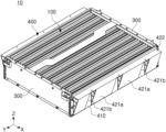
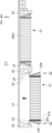
도 1은 배터리 팩의 일부 분해 사시도이다.
도 2는 배터리 팩에 포함되는 배터리 모듈의 사시도이다.
도 3은 배터리 모듈의 분해 사시도이다.
도 4는 도 2의 II-II' 부분의 단면도이다.
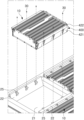
도 5는 배터리 모듈과 팩 하우징의 결합을 설명하기 위한 예시도이다.
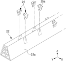
도 6은 팩 하우징의 서포트 프레임의 구조를 예시적으로 나타낸다.
도 7은 도 1의 I-I' 부분에 따른 예시적 단면도이다.
도 8은 다른 실시예들에 따른 배터리 모듈의 분해 사시도이다.
도 9는 배터리 팩의 팩 하우징에 배터리 모듈이 수용된 모습을 나타낸다.
도 10은 도 9의 IV-IV' 부분에 따른 예시적 단면도이다.1 is a partially exploded perspective view of a battery pack.
Figure 2 is a perspective view of a battery module included in a battery pack.
Figure 3 is an exploded perspective view of the battery module.
Figure 4 is a cross-sectional view taken along line II-II' of Figure 2.
Figure 5 is an example diagram for explaining the combination of a battery module and a pack housing.
Figure 6 exemplarily shows the structure of the support frame of the pack housing.
FIG. 7 is an exemplary cross-sectional view taken along portion II′ of FIG. 1 .
Figure 8 is an exploded perspective view of a battery module according to other embodiments.
Figure 9 shows a battery module accommodated in the pack housing of a battery pack.
FIG. 10 is an exemplary cross-sectional view taken along line IV-IV′ of FIG. 9 .
본 발명의 상세한 설명에 앞서, 본 명세서 및 청구범위에 사용된 용어나 단어는 통상적이거나 사전적인 의미로 한정해서 해석되어서는 아니 되며, 발명자는 그 자신의 발명을 가장 최선의 방법으로 설명하기 위해 용어의 개념으로 적절하게 정의할 수 있다는 원칙에 입각하여 본 발명의 기술적 사상에 부합하는 의미와 개념으로 해석되어야 한다. 따라서 본 명세서에 기재된 실시예와 도면에 도시된 구성은 본 발명의 가장 바람직한 실시예에 불과할 뿐, 본 발명의 기술적 사상을 모두 대변하는 것은 아니므로, 본 출원시점에 있어서 이들을 대체할 수 있는 다양한 균등물과 변형 예들이 있을 수 있음을 이해하여야 한다.Prior to the detailed description of the present invention, the terms or words used in the specification and claims should not be construed as limited to their usual or dictionary meanings, and the inventor uses terminology to explain his/her invention in the best way. It should be interpreted as meaning and concept consistent with the technical idea of the present invention based on the principle that it can be appropriately defined as a concept. Therefore, the embodiments described in this specification and the configurations shown in the drawings are only the most preferred embodiments of the present invention, and do not represent the entire technical idea of the present invention, and therefore, various equivalents that can replace them at the time of filing the present application It should be understood that there may be variations and examples.
본 명세서에 첨부된 각 도면에 기재된 동일한 참조 번호 또는 부호는 실질적으로 동일한 기능을 수행하는 부품 또는 구성요소를 나타낸다. 설명 및 이해의 편의를 위해서, 서로 다른 실시예들에서도 동일한 참조번호 또는 부호를 사용하여 설명할 수 있다. 즉, 복수의 도면에서 동일한 참조 번호를 가지는 구성 요소를 도시하고 있다고 하더라도, 복수의 도면들이 모두 하나의 실시예를 의미하는 것은 아니다.The same reference numbers or symbols in each drawing attached to this specification indicate parts or components that perform substantially the same function. For convenience of explanation and understanding, different embodiments may be described using the same reference numerals or symbols. That is, even if components having the same reference number are shown in multiple drawings, the multiple drawings do not all represent one embodiment.
이하의 설명에서, 단수의 표현은 문맥상 명백하게 다르게 뜻하지 않는 한, 복수의 표현을 포함한다. "포함하다" 또는 "구성하다" 등의 용어는 명세서 상에 기재된 특징, 숫자, 단계, 동작, 구성 요소, 부품 또는 이들을 조합한 것이 존재함을 지정하려는 것이지, 하나 또는 그 이상의 다른 특징들이나 숫자, 단계, 동작, 구성 요소, 부품 또는 이들을 조합한 것들의 존재 또는 부가 가능성을 미리 배제하지 않는 것으로 이해되어야 한다.In the following description, singular expressions include plural expressions unless the context clearly dictates otherwise. Terms such as "comprise" or "consist" are intended to designate the presence of features, numbers, steps, operations, components, parts, or combinations thereof described in the specification, but are not limited to one or more other features or numbers, It should be understood that this does not exclude in advance the possibility of the presence or addition of steps, operations, components, parts, or combinations thereof.
또한, 이하의 설명에서 상측, 상부, 하측, 하부, 측면, 전면, 후면 등의 표현은 도면에 도시된 방향을 기준으로 표현한 것이며, 해당 대상의 방향이 변경되면 다르게 표현될 수 있음을 미리 밝혀둔다.In addition, in the following description, expressions such as upper, upper, lower, bottom, side, front, rear, etc. are expressed based on the direction shown in the drawing, and it should be noted in advance that if the direction of the object is changed, it may be expressed differently. .
또한, 본 명세서 및 청구범위에서는 구성요소들 간의 구별을 위하여 "제1", "제2" 등과 같이 서수를 포함하는 용어가 사용될 수 있다. 이러한 서수는 동일 또는 유사한 구성 요소들을 서로 구별하기 위하여 사용하는 것이며, 이러한 서수 사용으로 인하여 용어의 의미가 한정 해석되어서는 안될 것이다. 일 예로, 이러한 서수와 결합된 구성 요소는 그 숫자에 의해 사용 순서나 배치 순서 등이 제한 해석되어서는 안된다. 필요에 따라서는, 각 서수들은 서로 교체되어 사용될 수도 있다.Additionally, in this specification and claims, terms including ordinal numbers such as “first”, “second”, etc. may be used to distinguish between components. These ordinal numbers are used to distinguish identical or similar components from each other, and the meaning of the term should not be interpreted limitedly due to the use of these ordinal numbers. For example, components combined with these ordinal numbers should not be interpreted as having a limited order of use or arrangement based on the number. If necessary, each ordinal number may be used interchangeably.
이하, 첨부된 도면을 참조하여 본 발명의 실시예들을 설명한다. 다만, 본 발명의 사상은 제시되는 실시 예에 제한되지 아니한다. 예를 들어, 본 발명의 사상을 이해하는 통상의 기술자는 구성요소의 추가, 변경 또는 삭제 등을 통하여 본 발명의 사상의 범위 내에 포함되는 다른 실시예를 제안할 수 있을 것이나, 이 또한 본 발명의 사상의 범위 내에 포함된다고 할 것이다. 도면에서 요소들의 형상 및 크기 등은 보다 명확한 설명을 위해 과장될 수 있다.Hereinafter, embodiments of the present invention will be described with reference to the attached drawings. However, the idea of the present invention is not limited to the presented embodiments. For example, a person skilled in the art who understands the spirit of the present invention may suggest other embodiments that are included within the scope of the spirit of the present invention through addition, change, or deletion of components, but this is also within the scope of the present invention. It would be said to be included within the scope of thought. The shapes and sizes of elements in the drawings may be exaggerated for clearer explanation.
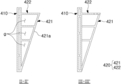
도 1은 배터리 팩(1)의 일부 분해 사시도이다. 도 2는 배터리 팩(1)에 포함되는 배터리 모듈(10)의 사시도이다. 도 3은 배터리 모듈(10)의 분해 사시도이다. 도 4는 사이드 커버의 예시적 단면도이다. 도 4에서 좌측 단면도는 도 3의 II-II' 부분에 따른 단면도이며, 우측 단면도는 도 3의 III-III' 부분의 단면도이다.1 is a partially exploded perspective view of the
배터리 팩(1)은 복수의 배터리 모듈(10) 및 배터리 모듈(10)이 수용되는 공간을 갖는 팩 하우징(20)을 포함할 수 있다.The
팩 하우징(20)은 배터리 모듈(10)의 하부를 커버하는 하부 프레임(21), 하부 프레임(21)과 연결되며 팩 하우징(20)의 적어도 일 측면을 형성하는 사이드 프레임, 하부 프레임(21)과 연결되며 사이드 프레임(23)과 다른 방향으로 연장되는 서포트 프레임(22) 및 배터리 모듈(10)의 상부를 커버하는 상부 프레임(24)을 포함할 수 있다.The pack housing 20 includes a
배터리 모듈(10)은 팩 하우징(20)에 일 방향(예를 들어, Z축 음의 방향)으로 삽입되어 배치될 수 있다. 예를 들어, 배터리 모듈(10)은 하부 프레임(21)의 상부면에 대해 수직한 방향으로 삽입되어 하부 프레임(21)에 안착될 수 있다. 이하의 설명에서, 배터리 모듈(10)이 팩 하우징(20)에 삽입되는 방향을 '삽입 방향'이라고 정의한다.The
복수의 배터리 모듈(10)은 각각 하나 이상의 배터리 셀(1000)을 포함하여, 전기적 에너지를 출력하거나 저장할 수 있도록 구성된다.The plurality of
배터리 모듈(10)에서, 복수의 배터리 셀들(1000)은 서로 적층되어 셀 적층체(100)의 적어도 일부를 구성할 수 있다. 배터리 모듈(10)은 셀 적층체(100)의 배터리 셀들(1000)과 전기적으로 연결되는 버스바 어셈블리(200), 버스바 어셈블리(200)를 커버하는 엔드 커버(300)를 더 포함할 수 있다.In the
셀 적층체(100)는 서로 전기적으로 연결된 복수의 배터리 셀들(1000)을 포함할 수 있다. 하나의 셀 적층체(100)에서, 복수의 배터리 셀들(1000)은 제1 방향(예를 들어, X축 방향)으로 적층 배치될 수 있다. 이하의 설명에서, 셀 적층체(100)에 포함되는 배터리 셀들(1000)의 적층 방향을 '제1 방향' 또는 '셀 적층 방향'이라고 한다.The
배터리 모듈(10)에 포함되는 배터리 셀(1000)은 파우치 내부에 전극 조립체(미도시)가 수납된 구조를 가지는 파우치형(pouch type) 이차전지일 수 있다. 파우치형 이차전지에서, 전극 조립체(미도시) 및 전해액(미도시)은 한 장 또는 복수의 외장재를 포밍(forming)하여 형성되는 파우치 내부에 수납될 수 있다. The
다만, 배터리 셀(1000)은 파우치형 이차전지로 한정되는 것은 아니다. 예를 들어, 배터리 셀은 각형의 캔형(can type) 이차전지로 구성되는 것도 가능하다. 또는, 배터리 셀은 복수의 파우치형 이차전지를 그룹화하여 번들로 형성한 구성을 갖는 것도 가능하다.However, the
예를 들어, 도 8을 참고하면, 배터리 셀(1000')은 강성을 가지는 케이스(1100) 내부에 전극 조립체(미도시)가 수납되는 형태의 각형 이차전지일 수 있다. 여기서, 배터리 셀(1000')은 전극 조립체(미도시), 케이스(1100) 및 캡 어셈블리(1200)를 포함할 수 있다. 케이스(1100)는 알루미늄, 알루미늄 합금 또는 니켈이 도금된 스틸과 같은 도전성 금속으로 형성될 수 있다. 케이스(1200)는 그 내부에 전극 조립체(미도시)가 삽입 및 안착될 수 있도록 적어도 일 방향으로 개방된 육면체 형상으로 이루어질 수 있다. 케이스(1100)의 내면은 절연 처리되어, 내부에 수용된 전극 조립체(미도시)와 절연될 수 있다. 각형 이차전지로 구성된 배터리 셀(1000')을 포함하는 배터리 모듈(10') 및 배터리 팩(1')에 관한 상세한 설명은 후술한다.For example, referring to FIG. 8, the battery cell 1000' may be a prismatic secondary battery in which an electrode assembly (not shown) is stored inside a
계속해서 도 1 내지 도 4를 참고하여 설명한다.The description continues with reference to FIGS. 1 to 4.
배터리 모듈(10)은 셀 적층체(100)의 배터리 셀들(1000)과 전기적으로 연결되는 버스바 어셈블리(200)를 포함할 수 있다. The
버스바 어셈블리(200)는 셀 적층체(100)의 적어도 일측에 배치되어, 배터리 셀들(1000) 상호간을 전기적으로 연결시킬 수 있다. 버스바 어셈블리(200)는 한 쌍으로 마련되어 셀 적층체(100)의 양 단에 각각 하나씩 배치될 수 있다. 다만, 한 쌍의 버스바 어셈블리(200)는 서로 연결되어 하나의 구성품으로 형성될 수도 있다.The
버스바 어셈블리(200)는 셀 적층체(100)의 배터리 셀들(1000)을 전기적으로 연결하는 복수의 버스바(210) 및 버스바(210)를 지지하는 버스바 프레임(220)을 포함할 수 있다.The
버스바(210)는 도전성 재료로 형성될 수 있으며, 복수의 배터리 셀(1000)을 서로 전기적으로 연결시키는 역할을 수행한다. 버스바(210)는 버스바 프레임(220)에 고정된 상태로 배터리 셀(1000)과 전기적으로 연결될 수 있다. 버스바(210) 중 적어도 일부에는 배터리 모듈(10)의 외부 회로와 전기적으로 연결될 수 있는 단자부(230)가 배치될 수 있다.The
버스바 프레임(220)은 버스바(210)가 배터리 셀(1000)과 안정적으로 연결되도록 지지할 수 있다. 버스바 프레임(220)은 소정의 강성을 가지는 비도전성 재료(예를 들어, 플라스틱)를 포함할 수 있으며, 복수의 버스바들(210)을 구조적으로 지지한다.The
버스바 프레임(220)은 셀 적층체(100)의 적어도 일측에 대향할 수 있다. 예를 들어, 도 3을 참고하면, 버스바 프레임(220)은 셀 적층체(100)와 제2 방향(예를 들어, Y축 방향)으로 대향하도록 배치될 수 있다. 여기서, 제2 방향(Y축 방향)은 제1 방향(X축 방향)에 수직한 방향일 수 있다. 이하의 설명에서, 제2 방향(Y축 방향)은 버스바 어셈블리(200)와 셀 적층체(100)가 서로 마주보는 방향과 나란한 방향을 의미할 수 있다.The
배터리 모듈(10)의 일측 최외곽에는 엔드 커버(300)가 배치될 수 있다. 엔드 커버(300)는 강성을 가지는 재료(예를 들어, 알루미늄 등의 금속이나 수지화합물)를 포함하여, 셀 적층체(100)를 외부의 충격으로부터 보호할 수 있다. An
엔드 커버(300)는 버스바 어셈블리(200) 또는 셀 적층체(100)에 결합되어 버스바(210)를 커버할 수 있다. 도면에 도시되지는 않으나, 엔드 커버(300)와 버스바(210)가 전기적으로 단락되는 것을 방지하기 위해, 엔드 커버(300)와 버스바 어셈블리(200) 사이에는 절연성 재료를 포함하는 절연 커버(미도시)가 배치될 수 있다.The
배터리 모듈(10)은 셀 적층체(100)의 적어도 일측에 대향하는 사이드 커버(400)를 포함할 수 있다. 사이드 커버(400)는 강성을 가지는 재료(예를 들어, 알루미늄 등의 금속이나 수지화합물)를 포함하여, 셀 적층체(100)를 외부의 충격으로부터 보호할 수 있다.The
사이드 커버(400)는 셀 적층체(100)의 서로 다른 면을 커버할 수 있도록 한 쌍으로 제공될 수 있다. 한 쌍의 사이드 커버(400)는 엔드 커버(300)와 각각 결합되어 배터리 모듈(10)의 측면을 구성하고, 셀 적층체(100)를 외부 환경으로부터 보호할 수 있다. 이 경우, 셀 적층체(100)는 한 쌍의 사이드 커버(400) 사이에 배치될 수 있다.The side covers 400 may be provided as a pair to cover different sides of the
사이드 커버(400)는 엔드 커버(300)와 서로 다른 방향으로 셀 적층체(100)와 대향할 수 있다. 예를 들어, 도 3에 도시된 바와 같이, 사이드 커버(400)는 셀 적층체(100)와 제1 방향(X축 방향)으로 마주보게 배치될 수 있으며, 엔드 커버(300)는 버스바 어셈블리(200)를 사이에 두고 셀 적층체(100)와 제2 방향(Y축 방향)으로 마주보게 배치될 수 있다. 이에 따라, 한 쌍의 엔드 커버(300), 한 쌍의 사이드 커버(400)는 배터리 모듈(10)의 네 면을 구성할 수 있다.The
사이드 커버(400)의 양 단부는 엔드 커버(300)와 결합될 수 있다. 사이드 커버(400)와 엔드 커버(300)의 결합에는 체결 부재(440)가 활용될 수 있다. 예를 들어, 복수의 체결 부재(440)가 사이드 커버(400)를 관통하여 엔드 커버(300)에 체결되고, 이에 따라 사이드 커버(400)와 엔드 커버(300)가 상호 고정될 수 있다. 다만, 사이드 커버(400)와 엔드 커버(300)의 결합 방식은 상술한 바에 한정되는 것은 아니다. 예를 들어, 사이드 커버(400)는 엔드 커버(300)와 용접되어 결합될 수 있다.Both ends of the
사이드 커버(400)는 배터리 셀(1000)의 적층 방향인 제1 방향(X축 방향)으로 배터리 셀(1000)과 대면할 수 있으며, 이에 따라, 배터리 셀(1000)에 면압을 제공할 수 있도록 구성될 수 있다.The
예를 들어, 배터리 셀(1000)의 충방전이 반복되는 경우, 배터리 셀(1000) 내부에서 발생된 가스에 의해 배터리 셀(1000)이 팽창하는 스웰링 현상이 발생되어, 배터리 셀(1000)의 전기적 성능이 저하될 우려가 있다. 이러한 스웰링 현상을 억제하기 위해, 사이드 커버(400)는 배터리 셀(1000)의 스웰링 발생에 따른 팽창압을 견딜 수 있도록 구성될 수 있다. 즉, 사이드 커버(400)는 셀 적층체(100)와 제1 방향(X축 방향)으로 대면하도록 배치되어, 배터리 셀(1000)에서 발생되는 제1 방향(X축 방향)의 팽창압에 반하는 면압을 제공할 수 있다.For example, when charging and discharging of the
도 2 및 도 3을 참고하면, 사이드 커버(400)는 셀 적층체(100)와 대면하는 바디부(410), 및 배터리 모듈이 팩 하우징에 안정적으로 결합되도록 가이드할 수 있는 가이드부(420)를 포함할 수 있다. 이 경우, 가이드부(420)는 바디부(410)에 연결되도록 구성될 수 있으며, 이에 따라 사이드 커버(400)의 구조적 강성을 더욱 증가시킬 수 있다.Referring to Figures 2 and 3, the
바디부(410)의 일면은 셀 적층체(100)와 제1 방향(X축 방향)으로 대면할 수 있다. 바디부(410)의 일면과 반대되는 타면에는 가이드부(420)가 배치될 수 있다. One surface of the
바디부(410)는 셀 적층체(100)가 팽창하는 경우 셀 적층체(100)에 면압을 가할 수 있도록 구성될 수 있다. 예를 들어, 바디부(410)는 배터리 셀(1000)의 넓은 면과 대면하도록 배치되어, 배터리 셀(1000)에 면압을 가할 수 있도록 구성될 수 있다.The
가이드부(420)는 바디부(410)와 연결되어 배터리 모듈(10)의 외측 방향으로 돌출되는 구조를 가질 수 있다. 가이드부(420)가 배치됨에 따라, 사이드 커버(400)는 단순히 판형 형상을 가질 때보다 더욱 큰 구조적 강성을 가질 수 있다.The
가이드부(420)는 바디부(410)로부터 돌출되는 연장부(422)를 포함할 수 있다. 연장부(422)는 바디부(410) 상에서 배터리 모듈의 외측 방향으로 돌출되는 구조를 가질 수 있다. 예를 들어, 제1 연장부(422)는 바디부(410)의 타면에서 제1 방향(X축 방향)으로 연장되도록 구성될 수 있으며, 이에 따라 바디부(410)에 대해 수직한 구조물의 형태를 가질 수 있다.The
가이드부(420)는 셀 적층 방향에 대해 경사진 제1 경사면(421a)을 가지는 경사부(421)를 포함할 수 있다. 예를 들어, 도 3를 참고하면, 경사부(421)의 제1 경사면(421a)은 제1 방향(X축 방향)에 대해 경사진 면일 수 있다. 또는, 경사부(421)의 제1 경사면(421a)은 바디부(410)의 일면{즉, 바디부(410)에서 셀 적층체(100)와 마주보는 면}에 대해 경사지게 구성될 수 있다.The
연장부(422)는 경사부(421)와 연결될 수 있다. 도 3 및 도 4를 참고하면, 경사부(421)는 연장부(422) 및 바디부(410)에 모두 연결될 수 있다. 예를 들어, 제1 경사면(421a)은 연장부(422)의 단부로부터 바디부(410)까지 이어지는 경사면일 수 있다.The
경사부(421)의 제1 경사면(421a)과 바디부(410) 사이에는 이격 공간이 형성될 수 있다. 도 4를 참고하면, 사이드 커버(400)는 경사부(421), 연장부(422) 및 바디부(410) 사이에 중공(g)이 형성된 구조를 가질 수 있다. 이러한 구조에 의할 경우, 가벼우면서도 구조적 강성이 우수한 사이드 커버(400)를 구현할 수 있다.A separation space may be formed between the first
경사부(421)와 바디부(410) 사이의 간격은 배터리 모듈(10)의 상측 방향으로 증가하도록 구성될 수 있다. 여기서 '배터리 모듈(10)의 상측 방향'은 도 3의 Z축 양의 방향을 의미할 수 있다.The gap between the
특히, 경사부(421)의 제1 경사면(421a)과 바디부(410)의 일면{셀 적층체(100)와 마주보는 면} 사이의 간격은 배터리 모듈(10)의 상측 방향으로 증가하도록 구성될 수 있다. In particular, the gap between the first
즉, 사이드 커버는 바디부(410) 및 가이드부(420)에 의해 형성되는 쐐기형 단면 구조를 가질 수 있다. 이러한 구조에 의해, 배터리 모듈(10)이 팩 하우징(20)에 조립되는 과정에서 사이드 커버(400)는 배터리 모듈(10)의 조립 위치를 가이드하는 역할을 수행할 수 있다.That is, the side cover may have a wedge-shaped cross-sectional structure formed by the
또한, 사이드 커버(400)는 바디부(410), 연장부(422) 및 경사부(421)로 둘러 쌓인 형태의 삼각형 또는 사다리꼴 형상의 단면 구조를 가질 수 있다. 이러한 구조에 의해, 사이드 커버는 배터리 셀의 팽창압을 보다 효과적으로 견딜 수 있다.Additionally, the
배터리 모듈(10)의 상부면 또는 하부면은 셀 적층체(100)가 노출되도록 구성될 수 있다. 예를 들어, 배터리 모듈(10)은 엔드 커버(300)와 사이드 커버(400)가 서로 결합되어 형성되는 사각 틀의 내부에 셀 적층체(100)가 배치된 구조를 가질 수 있으며, 셀 적층체(100)의 상부면 또는 하부면을 덮는 별도의 커버 부재를 가지지 않을 수 있다. 따라서 셀 적층체(100)의 배터리 셀들(1000)은 배터리 모듈(10)의 상부 방향 또는 하부 방향으로 노출될 수 있다. 이러한 구조에 의할 경우, 셀 적층체(100)가 배터리 모듈(10) 외부의 구성{예를 들어, 도 1에 도시된 배터리 팩(1)의 하부 프레임(21) 또는 방열 부재(미도시)}에 직접 맞닿을 수 있다. 이에 따라, 셀 적층체(100)로부터 배터리 모듈(10)의 상부 방향 또는 하부 방향으로 열 배출이 원활히 이루어질 수 있어, 배터리 모듈(10)의 방열 효율이 증가할 수 있다.The upper or lower surface of the
이하에서는 도 5 내지 도 7을 참고하여, 배터리 모듈(10)과 팩 하우징(20) 사이의 결합 구조에 관하여 상세히 설명한다.Hereinafter, with reference to FIGS. 5 to 7 , the coupling structure between the
도 5는 팩 하우징(20)에 배터리 모듈(10)이 안착되는 모습을 설명하기 위한 예시도이다. 도 6은 팩 하우징(20)의 서포트 프레임(22)의 구조를 예시적으로 나타낸다. 도 7은 도 1의 I-I' 부분에 따른 예시적 단면도이다.Figure 5 is an example diagram to explain how the
도 5 내지 도 7에서 설명되는 배터리 모듈(10) 및 배터리 팩(1)은 앞서 도 1 내지 도 4에서 설명되는 배터리 모듈(10) 및 배터리 팩(1)에 대응되는 것이므로, 중복되는 설명은 생략될 수 있다.Since the
복수의 배터리 모듈(10)은 팩 하우징(20)에 수용될 수 있다. 팩 하우징(20)은 배터리 모듈(10)이 안착되는 하부 프레임(21), 하부 프레임(21)의 상부에 배치되며 팩 하우징(20)의 일측면을 형성하는 사이드 프레임(23), 사이드 프레임(23) 사이에서 연장되는 복수의 서포트 프레임(22) 및 배터리 모듈(10)의 상부를 덮는 상부 프레임(24)을 포함할 수 있다.A plurality of
하부 프레임(21)은 팩 하우징(20)의 하부면을 형성한다. 하부 프레임(21)은 사각 판형 부재나 또는 다각 판형 부재로 구비될 수 있으나, 그 구체적인 형상이 이에 한정되는 것은 아니다.The
복수의 배터리 모듈(10)은 하부 프레임(21)의 상부에 안착될 수 있다. 예를 들어, 복수의 배터리 모듈(10)은 하부 프레임(21) 상에서 제1 방향(X축 방향) 또는 제2 방향(Y축 방향)을 따라 배열될 수 있다.A plurality of
하부 프레임(21)은 강성 가지는 금속 재질로 형성될 수 있다. 예를 들어, 하부 프레임(21)의 적어도 일부는 알루미늄을 포함할 수 있다. 하부 프레임(21)이 알루미늄을 포함하는 경우, 알루미늄의 뛰어난 열 전도성으로 인하여 배터리 모듈(10)에서 발생된 열 에너지가 배터리 팩(1) 외부로 신속하게 방열되는 효과를 기대할 수 있다. The
하부 프레임(21)과 배터리 모듈(10) 사이에는 방열 부재(미도시)가 배치될 수 있다. 방열 부재(미도시)는 일면은 배터리 모듈(10)의 셀 적층체(100)와 접촉되고, 일면과 반대되는 타면은 하부 프레임(21)과 접촉되게 배치될 수 있다. 방열 부재(미도시)는 열 전도성 접착제(Thermal adhesive)로 제공될 수 있다. 방열 부재(미도시)는 배터리 모듈(10)과 하부 프레임(21) 사이의 공간을 메워 전도에 의한 열 전달이 더욱 활발히 이루어지도록 할 수 있다. 이에 따라, 배터리 팩(1)의 방열 효율이 증대될 수 있다.A heat dissipation member (not shown) may be disposed between the
사이드 프레임(23)은 하부 프레임(21)과 연결되어 팩 하우징(20)의 적어도 일 측면을 형성할 수 있다. The
사이드 프레임(23)은 하부 프레임(21)의 상부에서 제1 방향(X축 방향)으로 연장되는 빔 구조물일 수 있다. 사이드 프레임(23)은 복수 개가 마련되어 하부 프레임(21)의 상면에서 제1 방향(X축 방향)에 수직한 제2 방향(Y축 방향)으로 이격 배치될 수 있다.The
서포트 프레임(22)은 하부 프레임(21) 및 사이드 프레임(23)과 연결될 수 있다. 예를 들어, 서포트 프레임(22)은 하부 프레임(21)의 상부면을 제2 방향(Y축 방향)으로 가로지르도록 배치될 수 있다.The
서포트 프레임(22) 팩 하우징(20)의 내부 공간을 구획하도록 배치될 수 있다. 예를 들어, 하부 프레임(21)의 상부면에서, 복수의 서포트 프레임(22)은 제1 방향(X축 방향)으로 이격되어 배치될 수 있으며, 이웃하는 두 서포트 프레임(22) 사이에 하나 이상의 배터리 모듈(10)이 배치될 수 있다.The
복수의 서포트 프레임(22) 중 적어도 일부는 배터리 모듈(10)의 사이에 배치될 수 있다. 예를 들어, 제1 방향(X축 방향)을 따라 배치되는 복수의 배터리 모듈(10) 사이에 서포트 프레임(22)이 배치될 수 있다. 따라서 서포트 프레임(22)은 배터리 모듈(10)과 제1 방향으로 대향할 수 있다.At least some of the plurality of support frames 22 may be disposed between the
하부 프레임(21)과 마찬가지로, 서포트 프레임(22)은 소정의 강성을 가지는 금속 재질로 형성될 수 있다. 예를 들어, 높은 방열 효과를 위해 서포트 프레임(22)의 적어도 일부는 알루미늄으로 형성될 수 있다.Like the
팩 하우징(20)은 배터리 모듈(10)의 상부에 배치되어 팩 하우징(20)의 내부 공간을 폐쇄하는 상부 프레임(24)을 포함할 수 있다. 상부 프레임(24)은 사이드 프레임(23) 또는 서포트 프레임(22)에 고정되어 배터리 모듈(10)의 상부를 덮을 수 있다. The pack housing 20 may include an
배터리 모듈(10)은 팩 하우징(20)의 하부 프레임(21)에 안착될 수 있다.The
배터리 모듈(10)은 팩 하우징(20)에 일 방향(예를 들어, 도 7의 Z축 음의 방향)으로 삽입되어 조립될 수 있다. 예를 들어, 배터리 모듈(10)은 제1 방향(X축 방향)에 수직한 방향(Z축 음의 방향)으로 팩 하우징에 삽입될 수 있다. 이하의 설명에서 배터리 모듈(10)이 팩 하우징(20)에 조립되는 방향을 '조립 방향'이라고 정의한다.The
배터리 모듈(10)은 서포트 프레임(22)과 결합되어 팩 하우징(20)에 고정될 수 있다. 예를 들어, 배터리 모듈(10)은 사이드 커버(400)가 서포트 프레임(22)과 결합될 수 있도록 구성될 수 있다.The
이 경우, 배터리 모듈(10)의 사이드 커버(400)는 결합 구조물로 활용될 수 있다. 예를 들어, 사이드 커버(400)는 팩 하우징(20)의 서포트 프레임(22)과 결합될 수 있으며, 이에 따라 배터리 모듈(10)이 팩 하우징(20) 내부에 견고하게 고정될 수 있다.In this case, the
복수의 서포트 프레임(22)은 하부 프레임(21)의 상부면을 따라 제1 방향(X축 방향)으로 이격 배치될 수 있다. 배터리 모듈(10)은 서포트 프레임(22)들의 사이에 배치될 수 있다.The plurality of support frames 22 may be arranged to be spaced apart in a first direction (X-axis direction) along the upper surface of the
서포트 프레임(22)의 제1 방향(X축 방향) 폭은 하부 프레임(21)에서 상부 프레임(24)을 향하는 방향으로 점차 좁아지도록 형성될 수 있다. 즉, 서포트 프레임(22)은 배터리 모듈(10)의 조립 방향(Z축 음의 방향)으로 점차 폭이 넓어지도록 구성될 수 있으며, 이에 따라 서포트 프레임(22)의 적어도 일 부분은 경사진 면으로 구성될 수 있다. 서포트 프레임(22)의 이러한 경사면은 제2 경사면(22a)으로 정의될 수 있다.The width of the
서포트 프레임(22)의 제2 경사면(22a)은 조립 방향(Z축 음의 방향)에 대해 경사진 면인 동시에, 제1 방향(X축 방향)에 대해 경사진 면으로 구성될 수 있다. 즉, 제2 경사면(22a)은 하부 프레임(21)의 상부면과의 사잇각(a2)이 둔각을 이루도록 경사질 수 있다.The second
어느 한 서포트 프레임(22)의 제2 경사면(22a)과 그에 이웃하는 서포트 프레임(22)의 제2 경사면(22a) 사이의 제1 방향(X축 방향)의 간격은 하부 프레임(21)에서 상부 프레임(24)을 향하는 방향(예를 들어, 도 7의 Z축 양의 방향)으로 증가할 수 있다.The gap in the first direction (X-axis direction) between the second
서포트 프레임(22)의 제2 경사면(22a)은 사이드 커버(400)의 제1 경사면(421a)과 대향할 수 있다.The second
한편, 제1 경사면(421a)과 하부 프레임(21)의 상부면의 사잇각(a1)은 예각을 형성할 수 있다. 도 7을 참고하면, 사이드 커버(400)는 하부 프레임(21)을 향하는 방향(예를 들어, Z축 음의 방향)으로 폭이 좁아지도록 구성될 수 있으며, 이 경우 사이드 커버(400)의 제1 경사면(421a)과 하부 프레임(21)이 형성하는 사잇각(a1)은 예각일 수 있다. Meanwhile, the angle a1 between the first
또는, 제1 경사면(421a)과 셀 적층체(100) 사이의 제1 방향(X축 방향)의 간격은 하부 프레임(21)에 가까워지는 방향으로 감소할 수 있다.Alternatively, the gap in the first direction (X-axis direction) between the first
제1 경사면(421a) 및 제2 경사면(22a)의 상술한 구조에 의해, 사이드 커버(400)는 배터리 모듈(10)의 안착 위치를 가이드하는 역할을 수행할 수 있다. 예를 들어, 배터리 모듈(10)은 제1 경사면(421a)이 제2 경사면(22a)을 따라 미끄러져 하부 프레임에(21) 안착되도록 구성될 수 있다.Due to the above-described structure of the first
도 7을 참고하면, 배터리 모듈(10)이 두 서포트 프레임(22) 사이에 배치되는 과정에서, 배터리 모듈(10)의 제1 경사면(421a)이 서포트 프레임(22)의 제2 경사면(22a)을 따라 슬라이딩될 수 있으며, 이에 따라 배터리 모듈(10)은 기설정된 위치에 자연스럽게 안착될 수 있다. 즉, 배터리 모듈(10)의 가이드부(420)는 배터리 모듈(10)이 신속하고 정확하게 팩 하우징(20)에 조립될 수 있도록 가이드할 수 있다.Referring to FIG. 7, in the process of placing the
제2 경사면(22a)은 제1 경사면(421a)과 대략 평행할 수 있다. 다만, 제2 경사면(22a)과 제1 경사면(421a)이 반드시 평행을 이루는 것은 아니다. 제2 경사면(22a)은 배터리 모듈(10)이 팩 하우징(20)에 안착되는 동안 제1 경사면(421a)이 제2 경사면(22a)을 타고 내려올 수 있을 정도로 기울어진 경사면으로 형성되면 족하다.The second
서포트 프레임(22)에는 배터리 모듈(10)을 향하는 방향으로 돌출되어 배터리 모듈(10)과 결합되는 결합부(25)가 배치될 수 있다.A
도 6을 참고하면, 결합부(25)는 서포트 프레임(22)의 제2 경사면(22a) 상에 배치될 수 있다. 예를 들어, 결합부(25)는 서포트 프레임(22)과 별도의 부재로 마련되어 제2 경사면(22a)에 접합되거나 또는 용접될 수 있다. 또는 결합부(25)는 서포트 프레임(22)과 일체로 형성되되, 적어도 일부가 제2 경사면(22a) 상에서 배터리 모듈(10)을 향하는 방향으로 돌출되는 구조물일 수 있다.Referring to FIG. 6, the
결합부(25)는 서포트 프레임(22)과 동일한 재료로 형성될 수 있다. 다만, 결합부(25)의 재료는 이에 한정되는 것은 아니다.The
결합부(25)는 복수 개가 제2 방향(Y축 방향)으로 이격 배치될 수 있다. 도 6과 같이, 복수 개의 결합부(25)는 제2 경사면(22a) 상에서 일정한 간격을 가지고 제2 방향(Y축 방향)을 따라 배치될 수 있다.A plurality of
결합부(25)는 배터리 모듈(10)의 사이드 커버(400)와 결합될 수 있다. The
사이드 커버(400)는 결합부(25)와의 간섭을 피할 수 있는 구조를 가질 수 있다. 예를 들어, 사이드 커버(400)는 결합부(25)가 삽입될 수 있는 삽입 홈(421b)을 포함할 수 있다. 삽입 홈(421b)은 경사부(421)에 형성될 수 있다. 사이드 커버(400)는 삽입 홈(421b)을 통해 연장부(422) 중 적어도 일부분이 하부 프레임(21)을 향하는 방향으로 노출되도록 구성될 수 있다. 이에 따라, 서포트 프레임(22)의 결합부(25)가 삽입 홈(421b)에 삽입되면, 사이드 커버(400)의 연장부(422)는 결합부(25)와 마주보게 배치되거나 또는 결합부(25)에 안착될 수 있다.The
결합부(25)는 사이드 커버(400)의 연장부(422)가 안착되는 결합면(25a)을 포함할 수 있다. 결합면(25a)은 하부 프레임(21)의 상부면과 대략 평행하도록 구성될 수 있다. 또는, 결합면(25a)의 적어도 일부는 셀 적층 방향인 제1 방향(X축 방향)에 수직하도록 구성될 수 있다.The
체결 부재(30)가 연장부(422)를 관통하여 결합면(25a)에 체결되어 결합부(25)와 사이드 커버(400)가 상호 결속될 수 있다. 예를 들어, 체결 부재(30)는 나사 또는 볼트로 마련될 수 있다.The
다만, 결합부(25)와 배터리 모듈(10)의 결합 구조는 상술한 바에 한정되는 것은 아니다. 예를 들어, 별도의 체결 부재(30) 없이 서포트 프레임(22)의 결합부(25)와 배터리 모듈(10)의 사이드 커버(400)가 상호 끼움 결합될 수도 있다.However, the coupling structure of the
사이드 커버(400)와 서포트 프레임(22)이 결합됨에 따라, 사이드 커버(400)는 배터리 셀(1000)의 스웰링 현상에 따른 팽창압을 더욱 효과적으로 견딜 수 있다. 즉, 서포트 프레임(22)이 사이드 커버(400)와 견고하게 고정되어 사이드 커버(400)를 제1 방향(X축 방향)으로 지지할 수 있으므로, 사이드 커버(400)는 배터리 셀(1000)의 팽창압을 더욱 안정적으로 견딜 수 있다.As the
한편, 종래의 판상형 사이드 커버 및 팩 하우징 프레임에 비해, 실시예들에 따른 사이드 커버(400)와 서포트 프레임(22)은 서로 대향하는 경사면(421a, 22a)을 가지고 맞물리도록 구성되어, 구조적 강성 측면에서 보다 유리하다. 이에 따라, 사이드 커버(400)와 서포트 프레임(22)의 두께를 종래에 비해 축소시키면서도 배터리 팩(1)의 구조적 강성을 해치지 않을 수 있다. 또한, 사이드 커버(400)와 서포트 프레임(22)의 두께 축소로 인해 확보된 공간에 더욱 많은 배터리 셀들(1000)을 배치할 수 있으므로, 배터리 모듈(10) 및 배터리 팩(1)의 에너지 밀도를 더욱 높일 수 있다.Meanwhile, compared to the conventional plate-type side cover and pack housing frame, the
다른 실시예들에서, 배터리 모듈(10')에 포함되는 배터리 셀(1000')은 강성이 있는 케이스를 가지는 각형 이차전지로 구성될 수도 있다. 이하에서는 도 8 내지 도 10을 참고하여, 다른 실시예들에 따른 배터리 모듈(10') 및 배터리 팩(1')을 설명한다.In other embodiments, the battery cell 1000' included in the battery module 10' may be composed of a prismatic secondary battery having a rigid case. Hereinafter, the battery module 10' and the battery pack 1' according to different embodiments will be described with reference to FIGS. 8 to 10.
도 8은 다른 실시예들에 따른 배터리 모듈(10')의 분해 사시도이다. 도 9는 배터리 팩(1')의 팩 하우징(20)에 배터리 모듈(10')이 수용된 모습을 나타낸다. 도 10은 도 9의 IV-IV' 부분에 따른 예시적 단면도이다. 도 9에서는 팩 하우징(20)의 하부 프레임(21)과 사이드 프레임(23)에 의해 형성된 공간 중 일부에 배터리 모듈(10')이 수용된 모습을 나타내나, 이는 예시일 뿐이며, 나머지 공간에도 배터리 모듈(10')이 수용되거나 또는 배터리 팩의 다른 구성(예를 들어, 제어부(미도시))등이 수용될 수 있다.Figure 8 is an exploded perspective view of the battery module 10' according to other embodiments. Figure 9 shows the battery module 10' accommodated in the pack housing 20 of the battery pack 1'. FIG. 10 is an exemplary cross-sectional view taken along line IV-IV′ of FIG. 9 . In Figure 9, the battery module 10' is shown accommodated in a portion of the space formed by the
배터리 팩(1')에 수용되는 배터리 모듈(10')은 복수의 배터리 셀들(1000')이 적층된 셀 적층체(100'), 셀 적층체(100')의 적어도 일측을 커버하는 모듈 하우징(500), 셀 적층체(100')와 적층 방향으로 대면하는 사이드 커버(400)를 포함할 수 있다.The battery module 10' accommodated in the battery pack 1' includes a cell stack 100' in which a plurality of battery cells 1000' are stacked, and a module housing covering at least one side of the
배터리 셀(1000')은 강성을 가지는 케이스(1100) 내부에 전극 조립체(미도시)가 수납되는 형태의 각형 이차전지일 수 있다.The battery cell 1000' may be a prismatic secondary battery in which an electrode assembly (not shown) is stored inside a
배터리 셀(1000)은 전극 조립체, 케이스(1100) 및 캡 어셈블리(1200)를 포함할 수 있다. The
케이스(1100)는 알루미늄, 알루미늄 합금 또는 니켈이 도금된 스틸과 같은 도전성 금속으로 형성될 수 있다. 전극 조립체(미도시)는 전해액과 함께 케이스(1100)에 수납될 수 있다. 케이스(1100)는 전극 조립체(110)가 삽입 및 안착될 수 있도록 적어도 일 방향으로 개방된 육면체 형상으로 이루어질 수 있다. 케이스(1100)의 내면은 절연 처리되어, 전극 조립체(미도시)와 절연될 수 있다.
캡 어셈블리(1200)는 케이스(1100)의 상단 개구부를 밀봉하여, 케이스(1100) 내부 공간을 폐쇄할 수 있다. 캡 어셈블리(1200)의 적어도 일부는 케이스(1100)와 동일한 재질로 형성될 수 있으며, 케이스(1100)에 용접되어 결합될 수 있다.The cap assembly 1200 may seal the upper opening of the
캡 어셈블리(1200)는 전극 조립체(미도시)와 전기적으로 연결되는 전극 단자(1210)를 포함할 수 있다. 전극 단자(1210)는 금속으로 형성될 수 있다.The cap assembly 1200 may include an
배터리 셀들(1000')은 제1 방향(X축 방향)으로 적층 배치되어 셀 적층체(100')를 형성할 수 있다. 배터리 셀들(1000') 사이에는 배터리 셀들(1000')을 상호 고정시켜주는 접착 부재(미도시)가 배치될 수 있다. 예를 들어, 접착 부재(미도시)는 바인더성 재료로 구성되고, 이웃하는 두 배터리 셀(1000')의 케이스(1100) 사이에 도포되거나 배치되어, 배터리 셀들(1000')이 적층된 상태를 유지할 수 있도록 해준다.Battery cells 1000' may be stacked and arranged in a first direction (X-axis direction) to form a cell stack 100'. An adhesive member (not shown) may be disposed between the battery cells 1000' to secure the battery cells 1000' to each other. For example, an adhesive member (not shown) is made of a binder material and is applied or placed between the
도 8을 참고하면, 일체로 형성되는 상부 커버(510)가 셀 적층체(100')의 상부면을 커버하도록 배치될 수 있다. 엔드 커버(520)는 상부 커버(510)와 이어져 셀 적층체(100')의 측면을 커버할 수 있도록 구성될 수 있다. Referring to FIG. 8 , an
상부 커버(510)는 캡 어셈블리(1200)의 상부에 배치될 수 있다. 상부 커버(510)가 캡 어셈블리(1200)와 전기적으로 단락되는 것을 방지하기 위해, 배터리 모듈(10')은 상부 커버(510)와 셀 적층체(100') 사이에 비도전성 재료로 구성되는 절연 커버(미도시)를 더 포함할 수 있다. 다만, 상부 커버(510) 자체가 절연성 재료로 형성되는 경우, 절연 커버(미도시)는 생략될 수도 있다.The
상부 커버(510)와 엔드 커버(520)의 구체적인 형상은 도 8에 도시된 바에 한정되는 것은 아니다. 예를 들어, 모듈 하우징(500)의 상부 커버(510)는 복수 개로 마련될 수 있으며, 이 경우, 각각의 상부 커버(510)는 서로 다른 배터리 셀(1000')을 커버하도록 배치될 수도 있다.The specific shapes of the
모듈 하우징(500)은 배터리 모듈(10')의 하부 방향(예를 들어, Z축 음의 방향)으로 개방된 형상을 가질 수 있다. 예를 들어, 모듈 하우징(500)은 상부 커버(510)와 엔드 커버(520)가 서로 연결되며 하부가 개방된 역 'U'자 형상을 가질 수 있다.The module housing 500 may have a shape that is open in the downward direction of the battery module 10' (eg, in the negative Z-axis direction). For example, the module housing 500 may have an inverted 'U' shape in which the
따라서, 배터리 모듈(10')은 셀 적층체(100')의 하부면이 모듈 하우징(500)의 외부로 노출되는 구조를 가질 수 있다. 예를 들어, 배터리 셀(1000)은 캡 어셈블리(1200)가 모듈 하우징(500)의 상부 커버(510)와 대향하도록 배치될 수 있는데, 이에 따라 배터리 셀(1000')의 케이스(1100)의 하부면(1210)은 모듈 하우징(500)의 외부로 노출될 수 있다. 배터리 셀(1000')의 케이스(1100)가 노출된 구조를 가지므로, 배터리 모듈(10')의 방열 효율이 증가할 수 있다.Accordingly, the battery module 10' may have a structure in which the lower surface of the cell stack 100' is exposed to the outside of the module housing 500. For example, the
배터리 모듈(10')은 셀 적층체(100')와 제1 방향(X축 방향)으로 대향하는 사이드 커버(400)를 포함할 수 있다. 여기서 사이드 커버(400)의 구체적인 구조 및 특징은 앞서 도 1 내지 도 7에서 설명되는 사이드 커버(400)의 구조 및 특징과 대응될 수 있다. 즉, 사이드 커버(400)는 제1 방향(X축 방향)에 대해 경사진 제1 경사면(421a)을 포함할 수 있으며, 여기서 제1 경사면(421a)은 팩 하우징의 하부 프레임(21)과의 사잇각이 예각을 이루도록 기울어질 수 있다. 이 외에 사이드 커버(400)에 관한 상세한 설명은 도 1 내지 도 7에 관한 설명을 참고할 수 있다.The battery module 10' may include a
배터리 모듈(10')은 팩 하우징(20)에 결합될 수 있다. 도 9 및 도 10을 참고하면, 팩 하우징(20)은 배터리 모듈(10')이 안착되는 하부 프레임(21), 팩 하우징(20)의 일 측면을 형성하는 사이드 프레임(23), 배터리 모듈(10')이 결합되어 지지되는 서포트 프레임(22)을 포함할 수 있다. 여기서, 팩 하우징(20)은 앞서 도 1 내지 도 7에서 설명되는 팩 하우징(20)과 동일한 구조를 가지는 바, 이에 대한 구체적인 설명은 도 1 내지 도 7에 관한 설명을 참고할 수 있다.The battery module 10' may be coupled to the pack housing 20. Referring to Figures 9 and 10, the pack housing 20 includes a
또한, 팩 하우징(20)의 서포트 프레임(22) 제2 경사면(22a)을 가질 수 있으며, 제2 경사면(22a)에는 배터리 모듈(10')을 향하여 돌출되며 배터리 모듈(10')과 결합되는 결합부(25)가 배치될 수 있다. 배터리 모듈(10')의 사이드 커버(400)는 서포트 프레임(22)의 결합부(25)가 삽입될 수 있는 삽입 홈(421b)을 포함할 수 있다. 여기서, 서포트 프레임(22)과 배터리 모듈(10')의 결합 구조는 앞서 도 1 내지 도 7에서 설명되는 서포트 프레임(22)과 배터리 모듈(10)의 결합 구조와 대응될 수 있으므로, 이에 대한 구체적인 설명은 도 1 내지 도 7에 관한 설명을 참고할 수 있다.In addition, the
배터리 모듈(10, 10')은 셀 적층체(100, 100')의 상부 또는 하부를 덮는 별도의 커버 부재를 포함하지 않을 수 있지만, 셀 적층 방향으로 돌출되는 가이드부(420)를 가지는 사이드 커버(400) 구조를 채용하여, 종래의 배터리 모듈과 같거나 또는 그 이상의 구조적 강성을 가질 수 있다. 또한, 배터리 모듈(10, 10')은 별도의 상부 커버 또는 하부 커버를 가지지 않으므로 방열 효율도 증대될 수 있다.The
또한, 실시예들의 배터리 모듈(10, 10') 및 배터리 팩(1, 1')에 따르면, 특정한 사이즈를 가지는 하우징과 같은 구조물을 생략할 수 있으므로, 배터리 모듈(10, 10') 및 배터리 팩(1, 1')의 제작 비용을 감소시킬 수 있으며, 제조 공정의 효율이 증가할 수 있다.In addition, according to the
또한, 실시예들의 배터리 모듈(10, 10') 및 배터리 팩(1, 1')에 따르면, 제1 경사면(421a)을 가지는 사이드 커버(400) 및 이에 대응하는 제2 경사면(22a)을 가지는 팩 하우징(20) 구조를 채용하여, 배터리 팩(1, 1')의 조립성을 향상시킬 수 있다.In addition, according to the
또한, 실시예들의 배터리 모듈(10, 10') 및 배터리 팩(1, 1')에 따르면, 서로 대향하는 경사면을 가지는 사이드 커버(400) 및 서포트 프레임(22) 구조를 통해, 팩 하우징(20) 내부의 강성 부재들을 최소한의 사이즈로 축소 설계하고 에너지 요소(예를 들어, 배터리 셀)을 추가로 배치할 수 있다.In addition, according to the
또한, 서로 대향하는 경사면을 가지는 사이드 커버(400) 및 서포트 프레임(22)은 배터리 모듈(10, 10')을 배터리 팩(1, 1')의 팩 하우징(20)과 견고하게 고정시키는 역할을 수행함과 동시에, 배터리 셀(1000, 1000')의 팽창압을 더욱 효과적으로 견딜 수 있는 보강 구조체의 역할을 수행할 수 있다. 이에 따라, 구조적으로 간결하면서도 배터리 셀(1000, 1000')의 스웰링 압력에 대해 높은 저항성을 가지는 배터리 팩(1, 1')을 구현할 수 있다.In addition, the
이상에서 본 발명의 다양한 실시예들에 대하여 상세히 설명하였지만, 본 발명의 권리범위는 이에 한정되는 것은 아니고, 청구범위에 기재된 본 발명의 기술적 사상을 벗어나지 않는 범위 내에서 다양한 수정 및 변형이 가능하다는 것은 당해 기술분야의 평균적인 지식을 가진 자에게는 자명할 것이다. 또한, 전술한 실시예에서 일부의 구성요소를 삭제하여 실시될 수 있고, 각 실시예들은 서로 조합되어 실시될 수도 있다.Although various embodiments of the present invention have been described in detail above, the scope of the present invention is not limited thereto, and various modifications and variations are possible without departing from the technical spirit of the present invention as set forth in the claims. This will be self-evident to anyone with average knowledge in the relevant technical field. Additionally, the above-described embodiments may be implemented by deleting some components, and each embodiment may be implemented in combination with each other.
1,1'... 배터리 팩
10, 10'... 배터리 모듈
20... 팩 하우징
21... 하부 프레임
22... 서포트 프레임
22a... 제2 경사면
23... 사이드 프레임
24... 상부 프레임
25... 결합부
30... 체결 부재
100, 100'... 셀 적층체
200... 버스바 어셈블리
300... 엔드 커버
400... 사이드 커버
410... 바디부
420... 가이드부
421a... 제1 경사면
421b... 삽입 홈
422... 연장부
1000, 1000'... 배터리 셀1,1'...
20... pack
22...
23...
25... joint 30... fastening member
100, 100'...
300...
410...
421a... first
422...
Claims (15)
상기 하나 이상의 배터리 모듈과 상기 제1 방향으로 대향하는 서포트 프레임을 포함하고,
상기 사이드 커버는
상기 서포트 프레임과 대면하며 상기 제1 방향에 대해 경사진 제1 경사면을 포함하는 배터리 팩.One or more battery modules including a cell stack including a plurality of battery cells stacked in a first direction, and a side cover facing the cell stack in the first direction; and
Comprising the one or more battery modules and a support frame facing the first direction,
The side cover is
A battery pack comprising a first inclined surface facing the support frame and inclined with respect to the first direction.
상기 하나 이상의 배터리 모듈이 안착되는 하부 프레임을 더 포함하고,
상기 제1 경사면과 상기 셀 적층체 사이의 상기 제1 방향의 간격은 상기 하부 프레임에 가까워지는 방향으로 감소하는 배터리 팩.According to claim 1,
Further comprising a lower frame on which the one or more battery modules are seated,
A battery pack in which the gap in the first direction between the first inclined surface and the cell stack decreases in a direction approaching the lower frame.
상기 서포트 프레임은 상기 제1 방향에 대해 경사진 제2 경사면을 포함하는 배터리 팩.According to clause 2,
The support frame includes a second inclined surface inclined with respect to the first direction.
상기 제1 경사면과 상기 하부 프레임의 상부면의 사잇각은 예각을 이루며,
상기 제2 경사면과 상기 하부 프레임의 상기 상부면의 사잇각은 둔각을 이루는 배터리 팩.According to clause 3,
The angle between the first inclined surface and the upper surface of the lower frame forms an acute angle,
The battery pack wherein the angle between the second inclined surface and the upper surface of the lower frame forms an obtuse angle.
상기 제1 경사면과 상기 제2 경사면은 서로 나란한 배터리 팩.According to clause 3,
The first inclined surface and the second inclined surface are parallel to each other in the battery pack.
상기 사이드 커버는
일면이 상기 셀 적층체와 상기 제1 방향으로 대면하는 바디부; 및
상기 바디부의 타면에서 돌출되어 상기 서포트 프레임에 결합되는 연장부를 더 포함하며,
상기 제1 경사면은 상기 연장부의 단부 및 상기 바디부에 연결되는 배터리 팩.According to clause 3,
The side cover is
a body portion with one surface facing the cell stack in the first direction; and
It further includes an extension part protruding from the other side of the body part and coupled to the support frame,
The first inclined surface is connected to an end of the extension portion and the body portion.
상기 서포트 프레임은 상기 제2 경사면에서 돌출되는 결합부를 더 포함하며,
상기 사이드 커버는 상기 결합부가 삽입되는 삽입 홈을 더 포함하는 배터리 팩.According to clause 6,
The support frame further includes a coupling portion protruding from the second inclined surface,
The battery pack wherein the side cover further includes an insertion groove into which the coupling part is inserted.
상기 연장부는 상기 삽입 홈을 통해 상기 서포트 프레임에 노출되는 배터리 팩.According to clause 7,
The extended portion is exposed to the support frame through the insertion groove.
상기 연장부를 관통하여 상기 결합부에 체결되는 체결 부재를 더 포함하는 배터리 팩.According to clause 7,
A battery pack further comprising a fastening member that penetrates the extension portion and is fastened to the coupling portion.
상기 결합부는 상기 연장부가 안착되며 상기 제1 방향을 따라 연장되는 결합면을 포함하며,
상기 체결 부재는 상기 결합면에 체결되는 배터리 팩.According to clause 9,
The coupling portion includes a coupling surface on which the extension portion is seated and extending along the first direction,
A battery pack wherein the fastening member is fastened to the coupling surface.
상기 결합부는 상기 제2 경사면 상에서 상기 제1 방향에 수직한 제2 방향을 따라 복수 개가 배치되는 배터리 팩.According to clause 7,
A battery pack in which a plurality of coupling portions are disposed along a second direction perpendicular to the first direction on the second inclined surface.
상기 제1 경사면과 상기 바디부 사이에 중공이 형성된 배터리 팩.According to clause 6,
A battery pack in which a hollow is formed between the first inclined surface and the body portion.
상기 사이드 커버는 한 쌍으로 제공되며,
상기 셀 적층체는 한 쌍의 상기 사이드 커버 사이에 배치되는 배터리 팩.According to claim 1,
The side covers are provided as a pair,
A battery pack in which the cell stack is disposed between a pair of side covers.
상기 하나 이상의 배터리 모듈은
상기 복수의 배터리 셀과 전기적으로 연결되는 버스바; 및
상기 버스바와 상기 제1 방향에 수직한 제2 방향으로 대향하는 엔드 커버를 더 포함하며,
상기 사이드 커버는 상기 엔드 커버와 결합되는 배터리 팩.According to claim 1,
The one or more battery modules
A bus bar electrically connected to the plurality of battery cells; and
Further comprising an end cover facing the bus bar in a second direction perpendicular to the first direction,
A battery pack in which the side cover is combined with the end cover.
상기 복수의 배터리 셀 중 적어도 하나는
전극 조립체가 수용되는 케이스; 및
상기 케이스에 결합되며, 전극 단자가 배치되는 캡 어셈블리를 포함하며,
상기 하나 이상의 배터리 모듈은 상기 캡 어셈블리의 상부에 배치되는 상부 커버를 더 포함하는 배터리 팩.According to claim 1,
At least one of the plurality of battery cells
A case in which the electrode assembly is accommodated; and
It is coupled to the case and includes a cap assembly on which electrode terminals are disposed,
The one or more battery modules further include an upper cover disposed on top of the cap assembly.
Priority Applications (6)
| Application Number | Priority Date | Filing Date | Title |
|---|---|---|---|
| KR1020220159545A KR20240077246A (en) | 2022-11-24 | 2022-11-24 | Battery pack |
| US18/359,040 US12237522B2 (en) | 2022-11-24 | 2023-07-26 | Battery pack comprising a support frame with an incline surface |
| EP25226798.4A EP4697472A3 (en) | 2022-11-24 | 2023-07-27 | Battery pack |
| EP23188013.9A EP4376184B1 (en) | 2022-11-24 | 2023-07-27 | Battery pack |
| CN202310927616.2A CN118073760A (en) | 2022-11-24 | 2023-07-27 | Battery pack |
| US19/023,698 US20250158186A1 (en) | 2022-11-24 | 2025-01-16 | Battery Pack |
Applications Claiming Priority (1)
| Application Number | Priority Date | Filing Date | Title |
|---|---|---|---|
| KR1020220159545A KR20240077246A (en) | 2022-11-24 | 2022-11-24 | Battery pack |
Publications (1)
| Publication Number | Publication Date |
|---|---|
| KR20240077246A true KR20240077246A (en) | 2024-05-31 |
Family
ID=87517341
Family Applications (1)
| Application Number | Title | Priority Date | Filing Date |
|---|---|---|---|
| KR1020220159545A Pending KR20240077246A (en) | 2022-11-24 | 2022-11-24 | Battery pack |
Country Status (4)
| Country | Link |
|---|---|
| US (2) | US12237522B2 (en) |
| EP (2) | EP4697472A3 (en) |
| KR (1) | KR20240077246A (en) |
| CN (1) | CN118073760A (en) |
Families Citing this family (3)
| Publication number | Priority date | Publication date | Assignee | Title |
|---|---|---|---|---|
| DE102022206721A1 (en) * | 2022-06-30 | 2024-01-04 | Robert Bosch Gesellschaft mit beschränkter Haftung | Electrochemical energy storage system, vehicle, method for fixing and positioning a component and pair of wedge bodies |
| DE102022119605A1 (en) * | 2022-08-04 | 2024-02-15 | Man Truck & Bus Se | Energy storage device for an electrically powered motor vehicle |
| DE102024118655A1 (en) * | 2024-07-02 | 2026-01-08 | Dr. Ing. H.C. F. Porsche Aktiengesellschaft | Cell stack protection device for a high-voltage battery |
Family Cites Families (9)
| Publication number | Priority date | Publication date | Assignee | Title |
|---|---|---|---|---|
| JP6680145B2 (en) * | 2016-08-24 | 2020-04-15 | トヨタ自動車株式会社 | Battery module |
| DE102017208754A1 (en) * | 2017-05-23 | 2018-11-29 | Mahle International Gmbh | Battery system for an electric vehicle |
| WO2019021912A1 (en) * | 2017-07-28 | 2019-01-31 | パナソニックIpマネジメント株式会社 | Linked battery module and linked battery pack |
| WO2019118849A1 (en) | 2017-12-15 | 2019-06-20 | Johnson Controls Technology Company | Hold-down assembly and device for a battery |
| CN209691826U (en) | 2019-06-04 | 2019-11-26 | 华霆(合肥)动力技术有限公司 | Power battery pack and electrokinetic cell system |
| EP3883007A1 (en) | 2020-03-20 | 2021-09-22 | Samsung SDI Co., Ltd. | A battery module, a method for assembling a battery module and a vehicle including a battery pack comprising at least one battery module |
| CN212810450U (en) | 2020-07-15 | 2021-03-26 | 比亚迪股份有限公司 | Battery tray, battery package and car |
| CN215816196U (en) | 2021-08-26 | 2022-02-11 | 中航锂电科技有限公司 | Battery module end plate, battery module and battery pack |
| CN217655954U (en) * | 2022-04-26 | 2022-10-25 | 蜂巢能源科技股份有限公司 | Battery packs and battery packs |
-
2022
- 2022-11-24 KR KR1020220159545A patent/KR20240077246A/en active Pending
-
2023
- 2023-07-26 US US18/359,040 patent/US12237522B2/en active Active
- 2023-07-27 EP EP25226798.4A patent/EP4697472A3/en active Pending
- 2023-07-27 CN CN202310927616.2A patent/CN118073760A/en active Pending
- 2023-07-27 EP EP23188013.9A patent/EP4376184B1/en active Active
-
2025
- 2025-01-16 US US19/023,698 patent/US20250158186A1/en active Pending
Also Published As
| Publication number | Publication date |
|---|---|
| US20240178496A1 (en) | 2024-05-30 |
| EP4376184A1 (en) | 2024-05-29 |
| EP4697472A3 (en) | 2026-04-22 |
| US20250158186A1 (en) | 2025-05-15 |
| EP4376184B1 (en) | 2026-02-11 |
| EP4697472A2 (en) | 2026-02-18 |
| US12237522B2 (en) | 2025-02-25 |
| CN118073760A (en) | 2024-05-24 |
Similar Documents
| Publication | Publication Date | Title |
|---|---|---|
| JP5889418B2 (en) | Battery module assembly with improved reliability and medium-to-large battery pack including the same | |
| EP3716392B1 (en) | Battery module having improved cooling structure | |
| EP3671946B1 (en) | Battery module having improved cooling structure | |
| EP2793289B1 (en) | Battery module | |
| KR20230134660A (en) | Battery module and battery pack including the same | |
| KR20240077246A (en) | Battery pack | |
| JP7049548B2 (en) | Battery module and battery pack containing it | |
| KR102541537B1 (en) | Battery module and battery pack including the same | |
| KR20120074425A (en) | Battery module and battery pack employed with the same | |
| KR20210074779A (en) | Cell module to prevent gas movement to nearby modules | |
| KR20160075068A (en) | Secondary Battery Cell Enhanced in Cooling Efficiency and Module-type Battery including the Same | |
| KR20230134376A (en) | Battery module | |
| KR20240012302A (en) | Battery pack and device including the same | |
| KR20230050093A (en) | Battery module and battery pack including the same | |
| US20230291036A1 (en) | Battery cell assembly and battery module including same | |
| KR20240073552A (en) | Battery module and battery pack including same | |
| EP4266465A1 (en) | Battery module | |
| KR20230170563A (en) | Battery pack and vehicle including the same | |
| KR20250020103A (en) | Battery module and battery pack including the same | |
| KR20240125343A (en) | Battery device comprising spacer | |
| KR102894091B1 (en) | Battery module and battery pack including the same | |
| KR20240067668A (en) | Battery pack | |
| EP4386946A1 (en) | Battery module and battery pack including the same | |
| KR20240030364A (en) | Battery module | |
| KR20250158505A (en) | Cell assembly and battery pack containing same |
Legal Events
| Date | Code | Title | Description |
|---|---|---|---|
| PA0109 | Patent application |
Patent event code: PA01091R01D Comment text: Patent Application Patent event date: 20221124 |
|
| PG1501 | Laying open of application |