KR20240077986A - Direct flushing module using radio frequency communication and automatic flushing device for toilet having the same - Google Patents
Direct flushing module using radio frequency communication and automatic flushing device for toilet having the same Download PDFInfo
- Publication number
- KR20240077986A KR20240077986A KR1020220160468A KR20220160468A KR20240077986A KR 20240077986 A KR20240077986 A KR 20240077986A KR 1020220160468 A KR1020220160468 A KR 1020220160468A KR 20220160468 A KR20220160468 A KR 20220160468A KR 20240077986 A KR20240077986 A KR 20240077986A
- Authority
- KR
- South Korea
- Prior art keywords
- flushing
- module
- toilet
- communication
- direct
- Prior art date
- Legal status (The legal status is an assumption and is not a legal conclusion. Google has not performed a legal analysis and makes no representation as to the accuracy of the status listed.)
- Pending
Links
Images


Classifications
-
- E—FIXED CONSTRUCTIONS
- E03—WATER SUPPLY; SEWERAGE
- E03D—WATER-CLOSETS OR URINALS WITH FLUSHING DEVICES; FLUSHING VALVES THEREFOR
- E03D5/00—Special constructions of flushing devices, e.g. closed flushing system
- E03D5/10—Special constructions of flushing devices, e.g. closed flushing system operated electrically, e.g. by a photo-cell; also combined with devices for opening or closing shutters in the bowl outlet and/or with devices for raising/or lowering seat and cover and/or for swiveling the bowl
- E03D5/105—Special constructions of flushing devices, e.g. closed flushing system operated electrically, e.g. by a photo-cell; also combined with devices for opening or closing shutters in the bowl outlet and/or with devices for raising/or lowering seat and cover and/or for swiveling the bowl touchless, e.g. using sensors
-
- H—ELECTRICITY
- H04—ELECTRIC COMMUNICATION TECHNIQUE
- H04W—WIRELESS COMMUNICATION NETWORKS
- H04W4/00—Services specially adapted for wireless communication networks; Facilities therefor
- H04W4/80—Services using short range communication, e.g. near-field communication [NFC], radio-frequency identification [RFID] or low energy communication
Landscapes
- Engineering & Computer Science (AREA)
- Computer Networks & Wireless Communication (AREA)
- Signal Processing (AREA)
- Aviation & Aerospace Engineering (AREA)
- Health & Medical Sciences (AREA)
- Life Sciences & Earth Sciences (AREA)
- Hydrology & Water Resources (AREA)
- Public Health (AREA)
- Water Supply & Treatment (AREA)
- Bidet-Like Cleaning Device And Other Flush Toilet Accessories (AREA)
Abstract
Description
본 발명은 RF 통신을 이용한 직수형 물내림 모듈 및 그를 구비한 변기용 자동 물내림 장치에 관한 것으로, 더욱 상세하게는, 인풋 모듈과 직수형 물내림 모듈이 전파 통신 방식으로 물내림 명령 신호를 송수신함으로써 물내림 작동이 정확하게 이루어질 수 있을 뿐만 아니라 사용자가 원하는 시기에 직관적으로 물내림을 할 수 있어 사용자의 편의성을 도모할 수 있는 직수형 물내림 모듈 및 그를 구비한 변기용 자동 물내림 장치에 관한 것이다. The present invention relates to a direct flushing module using RF communication and an automatic flushing device for a toilet equipped with the same. More specifically, the input module and the direct flushing module transmit and receive a flushing command signal through radio communication. The present invention relates to a direct flushing module that not only accurately performs the flushing operation but also allows the user to intuitively flush at the desired time, thus promoting user convenience, and an automatic flushing device for a toilet equipped with the same.
최근 들어, 변기에 IR 센서가 적용되어 사용자가 용변 후 직접 물내림 장치를 작동하지 않아도 자동으로 물내림이 이루어질 수 있다. Recently, IR sensors have been applied to toilets, allowing automatic flushing without the user having to manually operate the flushing device after using the toilet.
부연하면, 최근 유행한 COVID 19와 같은 코로나바이러스 및 세균 등의 감염으로 인한 전염병에 대하여 경각심이 높아지고 있으며, 따라서 불특정 다수가 사용하는 다중이용시설 중 예를 들면 화장실의 변기에 IR 센서의 적용이 늘어나고 있는 실정이다. In other words, awareness is increasing about infectious diseases caused by infections such as coronaviruses and bacteria, such as the recently prevalent COVID-19, and therefore, the application of IR sensors to toilets in restrooms, for example, among public facilities used by an unspecified number of people, is increasing. There is a situation.
아울러, 노인 및 장애인들과 같이 신체적 거동이 불편한 노약자들의 용변 후 센서의 센싱에 의해 자동 물내림이 실행되기 때문에 자동 물내림 장치가 확산되는 추세이다. In addition, automatic flushing devices are spreading because they are automatically flushed by a sensor after toileting for the elderly and the disabled, such as those with physical disabilities.
그러나, 종래의 자동 물내림 장치의 경우, IR 센서를 이용하여 사람의 신체의 위치를 감지한 다음 그 신호를 물내림 장치에 보내고 이를 통해 물내림 장치가 물을 내리는 방식이 적용되는데, IR 센서와 물내림 장치가 대부분 일체형으로 이루어져 있다. However, in the case of a conventional automatic flushing device, the position of the human body is detected using an IR sensor, and then the signal is sent to the flushing device, and the flushing device flushes water through the IR sensor. Most flushing devices are integrated.
이러한 종래의 장치의 경우, 사용자가 용변을 완전히 마무리한 다음 IR 센서가 인식할 수 있는 범위를 사용자가 벗어나야만 물내림 장치가 작동을 하기 때문에 직관적이지 못하다는 한계가 있다. 따라서, 노약자도 용변을 본 후 물을 내리기 위해 신체적 움직임을 해야 한다. 즉, 원하는 경우에도 즉시 물내림을 할 수 없는 한계가 있는 것이다. In the case of such a conventional device, there is a limitation in that it is unintuitive because the flushing device only operates when the user leaves the range that can be recognized by the IR sensor after the user has completely finished toileting. Therefore, even the elderly must make physical movements to flush the toilet after using the toilet. In other words, there is a limit to not being able to flush immediately even if desired.
아울러, IR 센서가 적용된 물내림 장치의 경우, 오작동할 우려가 있으며 사용자의 의도와는 상관없이 물이 임의로 내려가거나 또는 내려가야 할 때 내려가지 않을 수도 있다. In addition, in the case of a water flushing device with an IR sensor, there is a risk of malfunction, and the water may go down arbitrarily or not go down when it should, regardless of the user's intention.
또한, 종래의 IR 센서 적용 물내림 장치의 경우, 사용자가 용변 직후 바로 물내림을 원하는 경우에도 실행할 수 없을 뿐만 아니라 예를 들면 여성의 경우 용변 중에 용변 소리가 밖에 들리지 않게 하기 위해 용변과 동시에 물내림을 하기를 원할 수 있는데 이를 할 수 없는 한계도 있다. In addition, in the case of a conventional IR sensor applied flushing device, it is not possible even if the user wants to flush immediately after toileting. For example, in the case of women, flushing is done at the same time as toileting in order to prevent the sound of toileting from being heard outside. You may want to do this, but there are limitations that prevent you from doing so.
또한, 종래의 변기의 경우 변기 커버가 있기 때문에 설치에 대한 제약도 있다. Additionally, because conventional toilets have a toilet cover, there are restrictions on installation.
이에, 사용자가 물내림을 원하는 시기에 직관적이면서도 자동으로 할 수 있는 새로운 구성의 변기용 자동 물내림 장치의 개발이 요구되는 실정이다. Accordingly, there is a need to develop an automatic flushing device for a toilet with a new configuration that can intuitively and automatically flush the toilet when the user wants to flush it.
관련 선행기술로는 대한민국특허 등록번호 10-2411495호(발명의 명칭: 양변기의 자동과 수동 겸용 물내림 장치) 등이 있다. Related prior art includes Korean Patent Registration No. 10-2411495 (title of the invention: automatic and manual flushing device for toilet).
본 발명의 실시예는 인풋 모듈과 직수형 물내림 모듈이 전파 통신 방식으로 물내림 명령 신호를 송수신함으로써 물내림 작동이 정확하게 이루어질 수 있을 뿐만 아니라 사용자가 원하는 시기에 직관적으로 물내림을 할 수 있어 사용자의 편의성을 도모할 수 있는 RF 통신을 이용한 직수형 물내림 모듈 및 그를 구비한 변기용 자동 물내림 장치를 제공한다.In an embodiment of the present invention, the input module and the direct flushing module transmit and receive flushing command signals using radio communication, so that not only can the flushing operation be performed accurately, but the user can intuitively flush at the time desired by the user. Provides a direct flushing module using RF communication that can promote convenience and an automatic flushing device for a toilet equipped with the same.
본 발명이 해결하고자 하는 과제는 이상에서 언급한 과제(들)로 제한되지 않으며, 언급되지 않은 또 다른 과제(들)은 아래의 기재로부터 당업자에게 명확하게 이해될 수 있을 것이다.The problem to be solved by the present invention is not limited to the problem(s) mentioned above, and other problem(s) not mentioned will be clearly understood by those skilled in the art from the description below.
본 발명의 실시예에 따른 RF 통신을 이용한 직수형 물내림 모듈은, 인풋 모듈로부터 송신되는 물내림 신호를 받아 변기의 물을 자동으로 내리도록 하는 직수형 물내림 모듈로서, 물내림을 위한 물이 유입되는 유입구와 변기로 물을 유출하는 유출구를 포함하며, 상기 유입구와 상기 유출구를 잇는 이동관의 경로 상에 물의 이동을 차단 또는 허용하는 물내림 허용부가 장착되는 직수형 하우징과, 상기 직수형 하우징에 장착되며, 상기 인풋 모듈로부터 전파 통신(RF communication) 방식에 의해 상기 물내림 명령 신호를 수신하는 수신부가 구비되는 인쇄회로기판 조립체과, 상기 수신부에 의해 수신된 정보에 기초하여 상기 물내림 허용부를 작동시켜 상기 변기로의 물내림을 허용하는 솔레노이드 밸브를 포함할 수 있다. The direct flushing module using RF communication according to an embodiment of the present invention is a direct flushing module that automatically flushes the toilet by receiving a flushing signal transmitted from the input module, and water for flushing is provided. A direct-type housing including an inlet through which water flows in and an outlet through which water flows out into the toilet, and equipped with a flushing permitting part that blocks or allows the movement of water on the path of the moving pipe connecting the inlet and the outlet, and the direct-type housing A printed circuit board assembly is mounted and includes a receiving unit that receives the flushing command signal from the input module through radio frequency communication (RF communication), and operates the flushing permitting unit based on the information received by the receiving unit. It may include a solenoid valve that allows flushing into the toilet.
일측에 따르면, 상기 솔레노이드 밸브의 작동 시 상기 물내림 허용부는 상기 이동관의 일 구간이 차단 상태에서 개방 상태가 되도록 상승되고, 상기 솔레노이드 밸브의 미작동 시 상기 물내림 허용부는 상기 이동관의 일 구간을 다시 차단 상태가 되도록 원래의 위치로 복귀될 수 있다. According to one side, when the solenoid valve is operated, the flushing permitting portion is raised so that one section of the moving pipe is in an open state from a blocked state, and when the solenoid valve is not operated, the flushing allowing portion is raised to a section of the moving pipe again. It can be returned to its original position to become blocked.
일측에 따르면, 상기 이동관은, 상기 유입구와 수평으로 연결되는 수평 이동 구간 및 상기 유출구와 연결되는 수직으로 연결되는 수직 이동 구간을 포함하며, 상기 물내림 허용부는 상기 수직 이동 구간을 승강하면서 상기 이동관을 차단 또는 개방할 수 있다. According to one side, the moving pipe includes a horizontal moving section horizontally connected to the inlet and a vertical moving section vertically connected to the outlet, and the flushing allowance unit moves the moving pipe while lifting and lowering the vertical moving section. It can be blocked or opened.
일측에 따르면, 상기 수직 이동 구간의 상단부는 상방으로 돌출된 돌출 부분으로 형성되고, 상기 물내림 허용부는 상기 수직 이동 구간의 내경과 같거나 작은 외경을 가지되, 상단부는 상기 돌출 부분을 덮도록 측방으로 연장된 연장 부분으로 형성되어 상기 이동관의 차단 시 상기 물내림 허용부의 상기 연장 부분이 상기 수직 이동 구간의 돌출 부분을 덮을 수 있다. According to one side, the upper end of the vertical movement section is formed as a protruding portion that protrudes upward, and the flushing allowance portion has an outer diameter equal to or smaller than the inner diameter of the vertical movement section, and the upper end is lateral so as to cover the protruding portion. It is formed as an extension part extending from the movable pipe, so that when the moving pipe is blocked, the extended part of the flushing allowance part can cover the protruding part of the vertical moving section.
일측에 따르면, 상기 직수형 하우징의 측부에 누름 가능하게 장착되며, 누름 동작 시 상기 물내림 허용부를 작동시켜 상기 변기로의 물내림을 가능하게 하는 수동 물내림 버튼부를 더 포함할 수 있다. According to one side, it may further include a manual flush button unit that is pressably mounted on a side of the straight-type housing and operates the flush permitting unit when pressed to enable flushing into the toilet.
일측에 따르면, 상기 물내림 허용부에는 상기 수동 물내림 버튼부의 누름 동작 시 상기 수동 물내림 버튼부의 단부에 의해서 가압되어 상기 물내림 허용부에 물 이동 경로가 발생되도록 하는 가압부재가 구비될 수 있다. According to one side, the flushing permitting portion is pressed by an end of the manual flushing button portion during a pressing operation of the manual flushing button portion, so that a water movement path is created in the flushing permitting portion. It may be provided with a pressing member. .
한편, 본 발명의 실시예에 따른 RF 통신을 이용한 변기용 자동 물내림 장치는, 사용자의 입력에 따라 물내림 명령 신호를 송신하는 인풋 모듈 및 상기 인풋 모듈로부터 받은 상기 물내림 명령 신호에 따라 변기의 물을 내리는 직수형 물내림 모듈을 포함하며, 상기 직수형 물내림 모듈은, 물내림을 위한 물이 유입되는 유입구와 변기로 물을 유출하는 유출구를 포함하며, 상기 유입구와 상기 유출구를 잇는 이동관의 경로 상에 물의 이동을 차단 또는 허용하는 물내림 허용부가 이동 가능하게 장착되는 직수형 하우징과, 기 직수형 하우징에 장착되며, 상기 인풋 모듈로부터 전파 통신(RF communication) 방식에 의해 상기 물내림 명령 신호를 수신하는 수신부가 구비되는 인쇄회로기판 조립체와, 상기 수신부에 의해 수신된 정보에 기초하여 상기 물내림 허용부를 작동시켜 상기 변기로의 물내림을 허용하는 솔레노이드 밸브를 포함할 수 있다.Meanwhile, an automatic flushing device for a toilet using RF communication according to an embodiment of the present invention includes an input module that transmits a flushing command signal according to a user's input, and flushing water in the toilet according to the flushing command signal received from the input module. It includes a direct flushing module for flushing, wherein the direct flushing module includes an inlet through which water flows in for flushing and an outlet through which water flows out into the toilet, and a path of a moving pipe connecting the inlet and the outlet. It is mounted on a vertical housing in which a flushing allowance part that blocks or allows the movement of water is movably mounted, and is mounted on the vertical housing, and receives the flushing command signal from the input module through radio frequency communication (RF communication). It may include a printed circuit board assembly provided with a receiving unit, and a solenoid valve that operates the flushing permitting unit based on information received by the receiving unit to allow flushing into the toilet.
일측에 따르면, 상기 솔레노이드 밸브의 작동 시 상기 물내림 허용부는 상기 이동관의 일 구간이 차단 상태에서 개방 상태가 되도록 상승되고, 상기 솔레노이드 밸브의 미작동 시 상기 물내림 허용부는 상기 이동관의 일 구간을 다시 차단 상태가 되도록 할 수 있다. According to one side, when the solenoid valve is operated, the flushing permitting portion is raised so that one section of the moving pipe is in an open state from a blocked state, and when the solenoid valve is not operated, the flushing allowing portion is raised to a section of the moving pipe again. It can be placed in a blocked state.
일측에 따르면, 상기 이동관은, 상기 유입구와 수평으로 연결되는 수평 이동 구간 및 상기 유출구와 연결되는 수직으로 연결되는 수직 이동 구간을 포함하며, 상기 물내림 허용부는 상기 수직 이동 구간을 승강하면서 상기 이동관을 차단 또는 개방하며, 상기 수직 이동 구간의 상단부는 상방으로 돌출된 돌출 부분으로 형성되고, 상기 물내림 허용부는 상기 수직 이동 구간의 내경과 같거나 작은 외경을 가지되, 상단부는 상기 돌출 부분을 덮도록 측방으로 연장된 연장 부분으로 형성되어 상기 이동관의 차단 시 상기 물내림 허용부의 상기 돌출 부분이 상기 수직 이동 구간의 돌출 부분을 덮을 수 있다. According to one side, the moving pipe includes a horizontal moving section horizontally connected to the inlet and a vertical moving section vertically connected to the outlet, and the flushing allowance unit moves the moving pipe while lifting and lowering the vertical moving section. Blocked or opened, the upper end of the vertical movement section is formed as a protruding portion protruding upward, and the flushing allowance portion has an outer diameter equal to or smaller than the inner diameter of the vertical movement section, and the upper end covers the protruding portion. It is formed as an extension part extending laterally, so that when the moving pipe is blocked, the protruding part of the flushing allowance part can cover the protruding part of the vertical moving section.
일측에 따르면, 상기 인풋 모듈은, 버튼부가 노출되게 장착되는 모듈 하우징 및 상기 모듈 하우징 내에 장착되며, 상기 버튼부의 누름 동작을 인식하는 버튼 인식부재가 구비되는 인쇄회로기판 조립체를 포함하며, 상기 송신부는 상기 버튼부재의 인식 시 상기 수신부로 상기 물내림 명령 신호를 송신할 수 있다. According to one side, the input module includes a module housing in which a button portion is mounted to be exposed, and a printed circuit board assembly mounted in the module housing and provided with a button recognition member that recognizes a pressing operation of the button portion, and the transmitting unit When the button member is recognized, the flushing command signal can be transmitted to the receiver.
일측에 따르면, 상기 모듈 하우징은, 상기 버튼부가 누름 가능하게 구비되며, 상기 인쇄회로기판 조립체가 내장되는 전면 하우징부재와, 상기 전면 하우징부재에 결합되며, 배터리가 착탈 가능하게 결합되는 배터리 결합 부분을 구비하는 후면 하우징부재와, 상기 버튼부가 관통되는 버튼 관통홀이 구비되며, 상기 전면 하우징부재를 커버하는 전면 커버부재 및 상기 배터리 결합 부분을 커버하는 후면 커버부재를 포함하며, 상기 배터리 결합 부분과 상기 후면 커버부재 사이에 러버 재질의 패드부재가 개재될 수 있다. According to one side, the module housing includes a front housing member in which the button portion is pressably provided and the printed circuit board assembly is embedded, and a battery coupling portion coupled to the front housing member and to which the battery is detachably coupled. It includes a rear housing member, a button through-hole through which the button portion passes, a front cover member that covers the front housing member, and a rear cover member that covers the battery coupling portion, wherein the battery coupling portion and the A pad member made of rubber may be interposed between the rear cover members.
일측에 따르면, 상기 인풋 모듈은, 상기 모듈 하우징 또는 상기 인쇄회로기판 조립체에 장착되며, 상기 사용자의 신체의 일부의 근접을 센싱하는 근접 센서를 더 포함하며, 상기 근접 센서에 의해 상기 사용자의 접근이 인식되는 경우 상기 송신부는 상기 물내림 장치의 상기 수신부로 물내림 명령 신호를 송신할 수 있다. According to one side, the input module is mounted on the module housing or the printed circuit board assembly and further includes a proximity sensor that senses the proximity of a part of the user's body, and the proximity sensor detects the user's approach. When recognized, the transmitting unit may transmit a flushing command signal to the receiving unit of the flushing device.
본 발명의 실시예에 따르면, 인풋 모듈과 직수형 물내림 모듈이 전파 통신 방식으로 물내림 명령 신호를 송수신함으로써 물내림 작동이 정확하게 이루어질 수 있을 뿐만 아니라 사용자가 원하는 시기에 직관적으로 물내림을 할 수 있어 사용자의 편의성을 도모할 수 있다.According to an embodiment of the present invention, the input module and the direct flushing module transmit and receive flushing command signals through radio communication, so that not only can flushing be performed accurately, but also intuitively flush at the time desired by the user. This can promote user convenience.
도 1은 본 발명의 일 실시예에 따른 RF 통신을 이용한 변기용 자동 물내림 장치의 구성 및 작동을 개략적으로 도시한 도면이다.
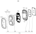
도 2는 도 1에 도시된 인풋 모듈의 분해 사시도이다.
도 3은 도 1에 도시된 인풋 모듈의 단면도 및 부분 확대 도면이다.
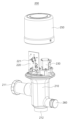
도 4는 도 1에 도시된 직수형 물내림 모듈의 사시도이다.
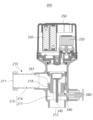
도 5는 도 4에 도시된 직수형 물내림 모듈의 내부 구성을 도시한 단면도이다.
도 6은 본 발명의 일 실시예에 따른 변기용 자동 물내림 장치의 인풋 모듈과 직수형 물내림 모듈이 전파 통신 방식으로 폴링(polling) 방식이 적용되는 경우의 작동 과정을 나타낸 순서도이다.
도 7은 본 발명의 다른 실시예에 따른 변기용 자동 물내림 장치의 인풋 모듈과 직수형 물내림 모듈이 전파 통신 방식으로 인터럽트(interrupt) 방식이 적용되는 경우의 작동 과정을 나타낸 순서도이다. Figure 1 is a diagram schematically showing the configuration and operation of an automatic flushing device for a toilet using RF communication according to an embodiment of the present invention.
FIG. 2 is an exploded perspective view of the input module shown in FIG. 1.
FIG. 3 is a cross-sectional view and a partially enlarged view of the input module shown in FIG. 1.
Figure 4 is a perspective view of the direct flushing module shown in Figure 1.
Figure 5 is a cross-sectional view showing the internal configuration of the direct flushing module shown in Figure 4.
Figure 6 is a flow chart showing the operation process when the polling method is applied to the input module and the direct flushing module of the automatic flushing device for a toilet according to an embodiment of the present invention.
Figure 7 is a flowchart showing the operation process when an interrupt method is applied to the input module and the direct flushing module of the automatic flushing device for a toilet according to another embodiment of the present invention.
본 발명의 이점 및/또는 특징, 그리고 그것들을 달성하는 방법은 첨부되는 도면과 함께 상세하게 후술되어 있는 실시예들을 참조하면 명확해질 것이다. 그러나, 본 발명은 이하에서 개시되는 실시예들에 한정되는 것이 아니라 서로 다른 다양한 형태로 구현될 것이며, 단지 본 실시예들은 본 발명의 개시가 완전하도록 하며, 본 발명이 속하는 기술분야에서 통상의 지식을 가진 자에게 발명의 범주를 완전하게 알려주기 위해 제공되는 것이며, 본 발명은 청구항의 범주에 의해 정의될 뿐이다. 명세서 전체에 걸쳐 동일 참조 부호는 동일 구성요소를 지칭한다.The advantages and/or features of the present invention and methods for achieving them will become clear by referring to the embodiments described in detail below in conjunction with the accompanying drawings. However, the present invention is not limited to the embodiments disclosed below and will be implemented in various different forms. The present embodiments only serve to ensure that the disclosure of the present invention is complete and are within the scope of common knowledge in the technical field to which the present invention pertains. It is provided to fully inform those who have the scope of the invention, and the present invention is only defined by the scope of the claims. Like reference numerals refer to like elements throughout the specification.
이하에서는 첨부된 도면을 참조하여 본 발명의 실시예들을 상세히 설명하기로 한다.Hereinafter, embodiments of the present invention will be described in detail with reference to the attached drawings.
도 1은 본 발명의 일 실시예에 따른 RF 통신을 이용한 변기용 자동 물내림 장치의 구성 및 작동을 개략적으로 도시한 도면이고, 도 2는 도 1에 도시된 인풋 모듈의 분해 사시도이고, 도 3은 도 1에 도시된 인풋 모듈의 단면도 및 부분 확대 도면이며, 도 4는 도 1에 도시된 직수형 물내림 모듈의 사시도이고, 도 5는 도 4에 도시된 직수형 물내림 모듈의 내부 구성을 도시한 단면도이다.Figure 1 is a diagram schematically showing the configuration and operation of an automatic flushing device for a toilet using RF communication according to an embodiment of the present invention, Figure 2 is an exploded perspective view of the input module shown in Figure 1, and Figure 3 is A cross-sectional view and a partially enlarged view of the input module shown in FIG. 1, FIG. 4 is a perspective view of the vertical flushing module shown in FIG. 1, and FIG. 5 shows the internal configuration of the vertical flushing module shown in FIG. 4. This is a cross-sectional view.
이들 도면에 도시된 것처럼, 본 발명의 일 실시예에 따른 변기용 자동 물내림 장치(1)는, 사용자의 입력에 따라 물내림 명령 신호(데이터 코드)를 송신하는 인풋 모듈(100)과, 인풋 모듈(100)로부터 받은 물내림 명령 신호에 따라 변기의 물을 자동으로 내리는 직수형 물내림 모듈(200)을 포함할 수 있다. As shown in these figures, the
인풋 모듈(100)과 직수형 물내림 모듈(200)이 전파 통신(RF communication) 방식으로 물내림 명령 신호를 송수신함으로써 물내림 작동이 정확하게 이루어질 수 있을 뿐만 아니라 사용자가 원하는 시기에 직관적으로 물내림을 할 수 있어 사용자의 편의성을 도모할 수 있다. The
각각의 구성에 대해 설명하면, 본 발명의 일 실시예에 따른 인풋 모듈(100)은, 도 1 및 도 2에 도시된 것처럼, 사용자의 입력에 의해 직수형 물내림 모듈(200)로 물내림 명령을 내리는 모듈로서, 버튼부(121)가 노출되게 장착되는 모듈 하우징(110)과, 모듈 하우징(110) 내에 장착되어 버튼부(121)의 누름 동작에 따라 물내림 명령 신호를 발생 및 송신하는 인쇄회로기판 조립체(150)를 포함할 수 있다. To describe each configuration, the
인쇄회로기판 조립체(150)에는, 버튼부(121)의 누름 동작을 인식하는 버튼 인식부재(151)와, 버튼 인식부재(151)의 인식 시 직수형 물내림 모듈(200)에 구비되는 수신부로 물내림 명령 신호를 송신하는 송신부가 구비될 수 있다. The printed
이러한 구성에 의해서, 사용자가 버튼부(121)를 누르면 이를 인쇄회로기판 조립체(150)에 장착된 버튼 인식부재(151)가 인식하고, 이후 송신부에 의해서 물내림 명령 신호를 전파 통신(RF communication) 방식을 이용하여 직수형 물내림 모듈(200)의 수신부로 보냄으로써 변기에서 물내림이 자동으로 실행될 수 있다. With this configuration, when the user presses the
도 1 및 도 2를 참조하면, 본 실시예의 버튼부(121)는 2개 구비될 수 있으며, 2개의 버튼부(121a, 121b) 중 하나의 버튼부(121a)는 용변이 대변인 경우 이에 해당되는 물내림 명령 신호를 발생시키는 버튼부(121a)이고, 다른 하나의 버튼부(121b)는 용변이 소변인 경우 이에 해당되는 물내림 명령 신호를 발생시키는 버튼부(121b)일 수 있다. Referring to Figures 1 and 2, two
버튼부(121a, 121b)들의 위치에 대응되도록 인쇄회로기판 조립체(150)에는 2개의 버튼 인식부재(151)가 구비될 수 있고, 버튼부(121a, 121b)의 누름 동작을 버튼 인식부재(151)가 각각 인식함으로써 해당되는 물내림 명령 신호를 발생시킬 수 있다. The printed
이처럼 본 실시예의 인풋 모듈(100)에는, 대변 및 소변을 구분할 수 있는 물리적인 버튼부(121)가 구비되기 때문에 대변 또는 소변의 종류에 따라 사용자가 물내림 방식을 선택할 수 있으며, 이를 통해 물 사용을 줄일 수 있다. In this way, the
부연하면, 대변 또는 소변에 각각 해당되는 버튼부(121)의 누름 동작에 따라, 각각의 물내림 명령 신호가 직수형 물내림 모듈(200)로 송신되고, 수신부를 통해 신호를 받은 직수형 물내림 모듈(200)에서 물내림에 대한 인터벌 시간을 조절함으로써 대변 또는 소변에 따른 물의 사용량을 조절할 수 있다. To elaborate, according to the pressing operation of the
한편, 전술한 것처럼, 사용자가 물리적인 버튼부(121)를 누름으로써 물내림 명령 신호를 발생시킬 수 있음은 물론 근접 센서 방식을 이용하여 물내림 명령 신호를 발생시킬 수 있다. Meanwhile, as described above, the user can generate a flushing command signal by pressing the
도시하지는 않았지만, 본 실시예의 모듈 하우징(110)의 전면에는 사용자의 신체의 일부, 예를 들면 손의 근접을 센싱하는 근접 센서가 장착될 수 있다. 근접 센서에 의해 사용자의 접근이 인식되는 경우, 송신부는 직수형 물내림 모듈(200)의 수신부로 물내림 명령 신호를 송신할 수 있으며, 이에 따라 직수형 물내림 모듈(200)의 작동에 의해서 자동으로 변기의 물을 내릴 수 있다.Although not shown, a proximity sensor that senses the proximity of a part of the user's body, for example, a hand, may be mounted on the front of the
부연하면, 근접 센서는 사용자의 손이 접근 시 주파수 변위를 감지할 수 있다. 아울러, 근접 센서에 대한 사용자의 손의 센싱 시간에 따라 대변 또는 소변에 따른 물내림 명령 신호를 내릴 수 있다. In detail, the proximity sensor can detect frequency displacement when the user's hand approaches. In addition, a flushing command signal according to feces or urine can be issued depending on the sensing time of the user's hand on the proximity sensor.
예를 들면, 설정된 센싱 시간이 있고, 이보다 더 길게 근접 센서에 대한 센싱이 이루어지는 경우 대변에 대한 물내림 명령 신호가 내려질 수 있고, 설정된 센싱 시간보다 짧게 센싱이 이루어지는 경우 소변에 대한 물내림 명령 신호가 내려질 수 있다. For example, there is a set sensing time, and if sensing is performed on the proximity sensor for longer than this, a flushing command signal for feces may be issued, and if sensing is performed shorter than the set sensing time, a flushing command signal for urine may be issued. can be issued.
이러한 근접 센서에 의해 물내림이 가능하기 때문에, 불특정 다수가 사용하는 다중이용 시설의 화장실에서 언택트(untact)로 자동 물내림을 할 수 있으며, 이에 따라 접촉으로 인한 전염병 감염을 방지할 수 있을 뿐만 아니라 위생을 확보할 수 있다. Since flushing is possible with this proximity sensor, automatic flushing can be done without contact in the bathroom of a multi-use facility used by an unspecified number of people, thereby preventing infectious diseases due to contact. However, hygiene can be ensured.
이처럼, 본 실시예의 경우, 인풋 모듈(100)의 버튼부(121) 또는 근접 센서 등을 이용하여 직수형 물내림 모듈(200)로 물내림 명령 신호를 내릴 수 있으며, 따라서 사용자가 원하는 시기에 직관적으로 변기의 물을 내릴 수 있다. 이를 통해, 용변 후에도 물을 내릴 수 있지만, 용변 중에도 물을 내릴 수 있어 예를 들면 여성의 에티켓에 대한 니즈를 제공해줄 수 있다. As such, in the case of this embodiment, a flushing command signal can be issued to the
본 실시예의 모듈 하우징(110)은, 도 2 및 도 3에 도시된 것처럼, 버튼부(121)가 누름 가능하게 구비되는 전면 하우징부재(120)와, 이에 결합되며 배터리(131)가 결합되는 배터리 결합 부분(132)을 구비하는 후면 하우징부재(130)와, 전면 하우징부재(120)를 커버하는 전면 커버부재(141)와, 배터리 결합 부분(132)을 커버하는 후면 커버부재(145)와, 배터리 결합 부분(132)과 후면 커버부재(145) 사이에 개재되는 패드부재(135)를 포함할 수 있다. As shown in FIGS. 2 and 3, the
먼저, 본 실시예의 전면 하우징부재(120)에는, 도 2 및 도 3에 도시된 것처럼, 상하로 배치되는 2개의 버튼부(121a, 121b)가 누름 가능하도록 구비되며, 내측 공간에는 인쇄회로기판 조립체(150)가 장착될 수 있다. 전면 하우징부재(120)는 일체형으로 마련될 수 있는데, 신축성이 있는 실리콘 또는 러버 재질로 마련될 수 있으나, 재질이 이에 한정되는 것은 아니다. First, the
전면 하우징부재(120)가 신축성 있는 재질로 마련되기 때문에 내측에 있는 인쇄회로기판 조립체(150)에 충격이 가해지는 것을 방지할 수 있으며, 이를 통해 내구성을 가질 수 있다. Since the
전술한 것처럼, 2개의 버튼부(121)에 인쇄회로기판 조립체(150)의 2개의 버튼 인식부재(151)가 맞닿도록 전면 하우징부재(120)에 인쇄회로기판 조립체(150)가 장착될 수 있다. As described above, the printed
아울러, 전면 하우징부재(120)에는 사용자의 접근을 센싱하는 근접 센서가 장착될 수 있다. 근접 센서는, 버튼부(121a, 121b)들 사이에 장착되거나 전면 하우징부재(120)의 전면의 둘레를 따라 마련될 수 있다. In addition, the
본 실시예의 후면 하우징부재(130)에는, 도 2에 도시된 것처럼, 2개의 배터리(131)가 병렬로 착탈 가능하게 결합되는 배터리 결합 부분(132)이 구비되는데, 배터리(131)의 착탈을 위해서 후방으로 개구된 형상을 가진다. As shown in FIG. 2, the
본 실시예의 전면 커버부재(141)에는, 도 2에 도시된 것처럼, 2개의 버튼부(121)가 관통되는 2개의 버튼 관통홀(141h)이 구비되며, 전면 하우징부재(120)를 전체적으로 감쌀 수 있다. As shown in FIG. 2, the
전면 하우징부재(120)와 후면 하우징부재(130)가 결합되는 경우, 후면 하우징부재(130)의 내면으로부터 돌출된 지지 부분(133)들이 인쇄회로기판 조립체(150)를 전면 하우징부재(120) 내측 방향으로 밀착시킬 수 있으며, 이를 통해 인쇄회로기판 조립체(150)의 위치가 견고하게 유지될 수 있다. When the
후면 하우징부재(130)의 배터리 결합 부분(132)에서 배터리(131)를 덮도록 패드부재(135)가 배치되며, 패드부재(135)를 덮도록 후면 커버부재(145)가 후면 하우징부재(130)에 결합될 수 있다. A
도 3의 우측 확대도를 참고하면, 전면 하우징부재(120)의 단부에는 바깥 방향으로 돌출된 돌출 부분(123)이 구비될 수 있고, 이에 대응되는 전면 커버부재(141)의 단부에는 돌출 부분(123)이 위치되는 단차 부분(142)이 구비될 수 있다. 아울러, 돌출 부분(123)과 단차 부분(142)이 결합되어 형성되는 결합홈에 후면 하우징부재(130)의 단부(138)가 삽입됨으로써 모듈 하우징(110)의 결합이 마무리될 수 있다. 즉, 오버랩(overlap) 구조를 가짐으로써 방수 구조를 구현할 수 있다. Referring to the enlarged view on the right side of Figure 3, the end of the
이를 통해, 외부로부터 물과 같은 액체가 모듈 하우징(110) 내부로 들어가는 것을 방지할 수 있다. 화장실의 경우 습기가 많을 수 있는데, 모듈 하우징(110)이 방수 구조를 가짐으로써 내부로 습기 또는 물이 침투하는 것을 방지할 수 있다. 이러한 방수 구조로 인해 본 실시예의 인풋 모듈(100)은 실외에도 설치 가능하다. Through this, it is possible to prevent liquid, such as water, from entering the
한편, 도 3의 좌측 확대도를 참고하면, 배터리 결합 부분(132)을 두르는 후면 하우징부재(130)의 외면에 내측으로 함몰된 방수홈(134)이 구비되고, 이에 대응되도록 패드부재(135)에는 방수홈(134)에 삽입되는 삽입돌기(136)가 띠 형상으로 구비됨으로써 배터리(131)가 결합된 배터리 결합 부분(132) 내로 물과 같은 액체가 침투되는 것을 방지할 수 있다. Meanwhile, referring to the enlarged view on the left of FIG. 3, a
다시 말해, 패드부재(135)가 배터리 결합 부분(132)을 덮도록 후면 하우징부재(130)에 결합되고, 또한 후면 커버부재(145)로 패드부재(135)를 덮어줌으로써 방수를 위한 오버랩 구조를 구현할 수 있는 것이다. In other words, the
한편, 이하에서는 전술한 인풋 모듈(100)과 전파 통신 방식에 의해 물내림 명령 신호를 받은 직수형 물내림 모듈(200)의 구성 및 작동에 대해서 설명하기로 한다. Meanwhile, hereinafter, the configuration and operation of the
도 1 및 도 4 그리고 도 5에 도시된 것처럼, 본 발명의 일 실시예에 따른 직수형 물내림 모듈(200)은, 전파 통신(RF communication) 방식에 의해 인풋 모듈(100)로부터 물내림 명령 신호를 받아 신호에 맞게 자동으로 변기의 물을 내리는 직수형 물내림 모듈(200)로서, 변기의 물을 내리기 위한 물이 유입되는 유입구(211)와 변기로 물을 유출하는 유출구(212)를 포함하며 유입구(211)와 유출구(212)를 잇는 이동관(215)의 경로 상에 물의 이동을 차단 또는 허용하는 물내림 허용부(240)가 장착되는 직수형 하우징(210)과, 직수형 하우징(210)에 장착되며 전파 통신 방식에 의해 물내림 명령 신호를 수신하는 수신부(221)가 구비되는 인쇄회로기판 조립체(220)와, 수신부(221)에 의해 수신된 정보에 기초하여 물내림 허용부(240)를 작동시켜 변기로의 물내림을 허용하는 솔레노이드 밸브(230)를 포함할 수 있다. As shown in FIGS. 1, 4, and 5, the
그리고 인쇄회로기판 조립체(220)와 솔레노이드 밸브(230)를 덮는 커버부(250)를 포함할 수 있다. And it may include a
이러한 구성에 의해서, 인풋 모듈(100)의 송신부와 직수형 물내림 모듈(200)의 수신부(221)가 물내림 명령 신호를 전파 통신 방식에 의해 송수신하면, 인쇄회로기판 조립체(220)에서 수신부(221)에 의해 수신된 물내림 명령 신호의 데이터 코드를 전기적인 신호로 처리한 다음 이 신호를 통해 솔레노이드 밸브(230)를 구동시킬 수 있으며, 이를 통해 물내림 허용부(240)가 개방되어 직수형 하우징(210)의 유입구(211)를 통해 유입된 물이 이동관(215)을 지나 유출구(212)를 통해 제공될 수 있으며, 이로 인해 변기의 물을 내릴 수 있다. With this configuration, when the transmitting unit of the
부연하면, 인풋 모듈(100)의 송신부로부터 송신된 물내림 명령 신호의 데이터 코드를 전기적 신호로 변환한 다음 이를 솔레노이드 밸브(230)에 전달함으로써 솔레노이드 밸브(230)의 작동에 의한 자동 물내림을 실행할 수 있는 것이다. To elaborate, the data code of the flushing command signal transmitted from the transmitter of the
더 구체적으로는, 솔레노이드 밸브(230)의 작동에 의해 이동관(215)에 구비되는 물내림 허용부(240)가 승강하여 이동관(215)을 차단하거나 개방할 수 있는데, 이를 통해 물내림을 조절할 수 있는 것이다. More specifically, by operating the
도 5를 참조하면, 솔레노이드 밸브(230)의 작동 시, 물내림 허용부(240)는 이동관(215)의 일 구간이 차단 상태에서 개방 상태가 되도록 상승되고, 반대로 솔레노이드 밸브(230)의 미작동 시 물내림 허용부(240)는 이동관(215)의 일 구간을 다시 차단 상태가 되도록 원래의 위치로 복귀될 수 있다. Referring to FIG. 5, when the
이러한 물내림 허용부(240)는, 전술한 것처럼, 직수형 하우징(210)의 유입구(211)와 유출구(212)를 연결하는 이동관(215)의 중앙 영역에서 승강 가능하게 장착됨으로써 승강에 의해 이동관(215)의 경로를 열거나 닫는데, 이를 위해 본 실시예의 이동관(215)은 기역자 형상으로 마련될 수 있다. As described above, this water
다시 말해, 본 실시예의 직수형 하우징(210)의 이동관(215)은, 유입구(211)와 수평으로 연결되는 수평 이동 구간(216)과, 유출구(212)와 수직으로 연결되는 수직 이동 구간(217)을 포함하며, 수직 이동 구간(217)과 수평 이동 구간(216)이 직교함으로써 전체적으로 기역자 형상을 가질 수 있다. 다만, 이동관(215)의 형상 및 구조가 이에 한정되는 것은 아니다. In other words, the moving
도 5를 참조하면, 물내림 허용부(240)는 이동관(215)의 수직 이동 구간(217)에서 승강 가능하게 장착될 수 있는데, 물내림 허용부(240)가 원래의 상태에서 승강하면 수평 이동 구간(216)과 수직 이동 구간(217)이 연통되어 물이 이동될 수 있는 것이고, 물내림 허용부(240)가 수직 이동 구간(217)에서 원래의 위치로 하강되면 물내림 허용부(240)가 수직 이동 구간(217)을 닫아버림으로써 물의 이동을 차단할 수 있는 것이다. Referring to FIG. 5, the
더 구체적으로는, 도 5에 도시된 것처럼, 수직 이동 구간(217)의 상단부는 수평 이동 구간(216)을 넘어서까지 돌출된 돌출 부분(218)으로 형성될 수 있다. 물내림 허용부(240)는 수직 이동 구간(217)의 내경에 대응되는 직경을 가질 수 있으며, 상단부는 돌출 부분(218)을 덮도록 측방으로 연장된 연장 부분(243)으로 형성될 수 있다. More specifically, as shown in FIG. 5, the upper end of the
이러한 구성에 의해서, 물내림 허용부(240)가 이동관(215)을 차단하는 경우 물내림 허용부(240)의 연장 부분(243)이 수직 이동 구간(217)의 돌출 부분(218)을 덮음으로써 물의 이동을 차단할 수 있다. 돌출 부분(218)과 맞닿은 연장 부분(243)에는 예를 들면 실링부재 등이 구비될 수 있으며, 이로 인해 물의 차단을 신뢰성 있게 할 수 있다. With this configuration, when the
한편, 전술한 것처럼, 직수형 물내림 모듈(200)에서 받을 수 있는 물내림 명령 신호로는 용변이 대변인 경우 주어지는 물내림 명령 신호가 있을 수 있고, 용변이 소변인 경우 주어지는 물내림 명령 신호가 있을 수 있다. Meanwhile, as described above, the flushing command signal that can be received from the
예를 들면, 용변이 대변인 경우 주어지는 물내림 명령 신호가 직수형 물내림 모듈(200)에 주어지는 경우, 솔레노이드 밸브(230)에 의해 물내림 허용부(240)는 설정된 시간 동안, 예를 들면 10 내지 15초 개방될 수 있으며, 7 내지 8리터 정도의 퇴수량으로 물 이동을 조절함으로써 물내림을 신뢰성 있게 할 수 있다. For example, when a flushing command signal given in the case of a toilet is given to the
또한, 예를 들면, 용변이 소변인 경우 주어지는 물내림 명령 신호가 직수형 물내림 모듈(200) 신호에 주어지는 경우, 솔레노이드 밸브(230)에 의해 물내림 허용부(240)는 설정된 시간 동안, 예를 들면 5 내지 7초 개방될 수 있으며, 5 내지 6리터 정도의 퇴수량으로 물 이동을 조절함으로써 물내림을 신뢰성 있게 할 수 있으며, 이를 통해 물 사용을 줄일 수 있다. In addition, for example, when the flushing command signal given when the toilet is urine is given to the
한편, 본 실시예의 직수형 물내림 모듈(200)은 전술한 것처럼 인풋 모듈(100)로부터 물내림 명령 신호를 받아서 자동으로 작동할 수 있으나, 이에 한정되는 것은 아니며 수동으로 작동이 가능하다. Meanwhile, the
이를 위해, 본 실시예의 직수형 물내림 모듈(200)은, 직수형 하우징(210)의 측부에 누름 가능하게 장착되며, 누름 동작 시 물내림 허용부(240)를 작동시켜 변기로의 물내림을 가능하게 하는 수동 물내림 버튼부(260)를 더 포함할 수 있다. To this end, the
도 5를 참조하면, 물내림 허용부(240)에는 수동 물내림 버튼부(260)의 누름 동작 시 수동 물내림 버튼부(260)의 단부에 의해서 가압되어 물내림 허용부(240)에 물 이동 경로가 발생되도록 하는 가압부재(245)가 구비될 수 있다. 즉, 수동 물내림 버튼부(260)의 단부가 가압부재(245)의 하단부를 가압하면 가압부재(245)가 일측으로 기울 수 있고, 그러면 가압부재(245)의 상단부가 물내림 허용부(240)의 일부분을 막고 있다가 개방되어 물의 이동이 가능해질 수 있는 것이다. Referring to FIG. 5, the
이를 통해, 인풋 모듈(100)과 직수형 물내림 모듈(200)의 전파 통신이 제대로 이루어지지 않거나, 직수형 물내림 모듈(200)의 구성이 제대로 작동하지 않는 경우, 수동 물내림 버튼부(260)를 수동으로 작동함으로써 물내림을 원활하게 할 수 있다. Through this, if radio wave communication between the
한편 이하에서는 도면의 순서도를 참조하여, 본 실시예의 인풋 모듈과 물내림 모듈의 전파 통식 방식에 대해서 설명하기로 한다. Meanwhile, hereinafter, the radio communication method of the input module and the flushing module of this embodiment will be described with reference to the flow chart in the drawing.
도 6은 본 발명의 일 실시예에 따른 변기용 자동 물내림 장치의 인풋 모듈과 직수형 물내림 모듈이 전파 통신 방식으로 폴링(polling) 방식이 적용되는 경우의 작동 과정을 나타낸 순서도이다. Figure 6 is a flow chart showing the operation process when the polling method is applied to the input module and the direct flushing module of the automatic flushing device for a toilet according to an embodiment of the present invention.
도 6에 도시된 것처럼, 폴링 방식은 순차적 다중 접근 방식으로서, 직수형 물내림 모듈(200)이 상시 대기 모드 시 발생되는 배터리의 소비 전류를 최소화하기 위해서 딥 슬립(deep sleep) 1초, 웨이크업(wake up) 0.02초를 한 후 다시 슬립 과정을 실행한다. 도 6에서 이러한 과정을 지속적으로 반복함으로써 대기 모드보다 배터리 소비 전류를 최소화할 수 있다. As shown in Figure 6, the polling method is a sequential multiple approach, and in order to minimize the battery current consumption generated when the
인풋 모듈(100)에 있어서는, 딥 슬립 모드에서 특정 버튼부(121)를 작동시키면, 1.02초 동안 물내림 명령 신호, 즉 데이터 코드를 전파 통신 방식에 의해 직수형 물내림 모듈(200)로 송신하게 된다. 이때, 전파 통신 방식의 종류는 블루투스(Bluetooth), 지그비(Zigbee), 와이파이(Wifi) 등일 수 있다. In the
직수형 물내림 모듈(200)에 있어서는, 배터리 소비 전류를 최소화하기 위해 딥 슬립 모드에서 주기적으로 딥 슬립 1초, 웨이크업 0.2초를 한 다음 다시 딥 슬립 모드를 지속적으로 반복할 수 있으며, 인풋 모듈(100)의 물내림 명령 신호를 수신 대기한다. In the
여기서, 인풋 모듈(100)의 신호 전송 시간을 1.02초로 정한 이유는 직수형 물내림 모듈(200)에서 주기적인 구간의 시간이 1.02초임을 감안한 것이며, 직수형 물내림 모듈(200)에서 명령 신호를 받지 못하는 상황을 방지하기 위해서 인풋 모듈(100)에서 물내림 명렁 신호의 전송 시간인 1.02초와 같게 한 것이다. Here, the reason for setting the signal transmission time of the
직수형 물내림 모듈(200)에서 인풋 모듈(100)에서 송신한 물내림 명령 신호를 받는데 성공하면, 직수형 물내림 모듈(200)에서 인풋 모듈(100)로 응답 신호를 전송하여 인풋 모듈(100)에서 물내림 명령 신호의 발송을 멈추고 다시 딥 슬립 모드에 들어가며, 이와 동시에 직수형 물내림 모듈(200)에 장착되어 있는 솔레노이드 밸브에 전기적 신호를 주어 자동으로 물내림이 이루어질 수 있다. If the
한편, 도 7은 본 발명의 다른 실시예에 따른 변기용 자동 물내림 장치의 인풋 모듈(100)과 직수형 물내림 모듈(200)이 전파 통신 방식으로 인터럽트(interrupt) 방식이 적용되는 경우의 작동 과정을 나타낸 순서도이다. Meanwhile, Figure 7 shows the operation process when the
도 7에 도시된 것처럼, 인터럽트 방식은 특정 이벤트 발생 시 해당 데이터를 처리하는 방식으로서 전술한 폴링 방식과는 다르게 직수형 물내림 모듈(200)이 주기적 모드를 가지지 않으며, 최소 전류로 동면 모드 상태를 가질 수 있다.As shown in FIG. 7, the interrupt method is a method of processing corresponding data when a specific event occurs. Unlike the polling method described above, the
인풋 모듈(100)로부터 물내림 명령 신호에 따른 특정 데이터 코드를 직수형 물내림 모듈(200)에서 받으면, 바로 웨이크업 및 스캔 과정을 0.1초 동안의 짧은 시간 안에 처리함으로써 배터리 소비 전류를 최소화할 수 있다. When the
인풋 모듈(100)이 딥 슬립 모드에서 특정의 버튼부(121)를 작동시키면 0.1초 동안 그에 해당하는 물내림 명령 신호를 전파 통신 방식으로 전송한다. When the
그러면, 직수형 물내림 모듈(200)에서는 0.1초 동안 물내림 명령 신호를 웨이크업 및 수신 처리한다. Then, the
전술한 폴링 방식과 비교 및 대조하면, 폴링 방식의 경우 직수형 물내림 모듈(200)이 주기적 구간을 가지나 인터럽트 방식은 인풋 모듈(100)에서 신호를 보낼 때만 웨이크업 하여 수신할 수 있는 기능을 사용하기 때문에 배터리 소비를 더욱 줄일 수 있다.Comparing and contrasting with the polling method described above, in the case of the polling method, the
인풋 모듈(100)에서 보낸 신호를 직수형 물내림 모듈(200)에서 받는 것을 성공하면, 직수형 물내림 모듈(200)에서 인풋 모듈(100)로 응답 신호를 전송하여 인풋 모듈(100)에서 물내림 명령 신호의 발송을 멈추고 다시 동면 모드에 들어가며, 이와 동시에 직수형 물내림 모듈(200)에 장착되어 있는 솔레노이드 밸브에 전기적 신호를 주어 자동으로 물내림이 이루어질 수 있다. If the
이와 같이, 본 발명의 실시예에 따르면, 인풋 모듈(100)과 직수형 물내림 모듈(200)이 전파 통신 방식으로 물내림 명령 신호를 송수신함으로써 물내림 작동이 정확하게 이루어질 수 있을 뿐만 아니라 사용자가 원하는 시기에 직관적으로 물내림을 할 수 있어 사용자의 편의성을 도모할 수 있다.As such, according to an embodiment of the present invention, the
지금까지 본 발명에 따른 구체적인 실시예에 관하여 설명하였으나, 본 발명의 범위에서 벗어나지 않는 한도 내에서는 여러 가지 변형이 가능함은 물론이다. 그러므로, 본 발명의 범위는 설명된 실시예에 국한되어 정해져서는 안 되며, 후술하는 특허 청구의 범위뿐 아니라 이 특허 청구의 범위와 균등한 것들에 의해 정해져야 한다.Although specific embodiments according to the present invention have been described so far, it goes without saying that various modifications are possible without departing from the scope of the present invention. Therefore, the scope of the present invention should not be limited to the described embodiments, but should be determined by the scope of the patent claims described below as well as equivalents to the claims of this patent.
이상과 같이 본 발명은 비록 한정된 실시예와 도면에 의해 설명되었으나, 본 발명은 상기의 실시예에 한정되는 것은 아니며, 이는 본 발명이 속하는 분야에서 통상의 지식을 가진 자라면 이러한 기재로부터 다양한 수정 및 변형이 가능하다. 따라서, 본 발명 사상은 아래에 기재된 특허청구범위에 의해서만 파악되어야 하고, 이의 균등 또는 등가적 변형 모두는 본 발명 사상의 범주에 속한다고 할 것이다.As described above, although the present invention has been described with reference to limited embodiments and drawings, the present invention is not limited to the above embodiments, and those skilled in the art can make various modifications and modifications from these descriptions. Transformation is possible. Accordingly, the spirit of the present invention should be understood only by the scope of the claims set forth below, and all equivalent or equivalent modifications thereof shall fall within the scope of the spirit of the present invention.
1: 변기용 자동 물내림 장치
100: 인풋 모듈
110: 모듈 하우징
120: 전면 하우징부재
121: 버튼부
130: 후면 하우징부재
131: 배터리
132: 배터리 결합 부분
135: 패드부재
141: 전면 커버부재
145: 후면 커버부재
150: 인쇄회로기판 조립체
151: 버튼 인식부재
200: 직수형 물내림 모듈
210: 직수형 하우징
211: 유입구
212: 유출구
215: 이동관
216: 수평 이동 구간
217: 수직 이동 구간
218: 돌출 부분
220: 인쇄회로기판 조립체
221: 수신부
230: 솔레노이드 밸브
240: 물내림 허용부
243: 연장 부분
245: 가압부재
250: 커버부
260: 수동 물내림 버튼부1: Automatic flushing device for toilet
100: input module
110: module housing
120: Front housing member
121: Button portion
130: Rear housing member
131: battery
132: Battery connection part
135: Pad member
141: Front cover member
145: Rear cover member
150: Printed circuit board assembly
151: Absence of button recognition
200: Direct flushing module
210: Direct housing
211: inlet
212: outlet
215: Lee Dong-gwan
216: Horizontal movement section
217: Vertical movement section
218: protruding part
220: Printed circuit board assembly
221: Receiving unit
230: Solenoid valve
240: flushing allowance part
243: Extension part
245: Pressure member
250: Cover part
260: Manual flush button part
Claims (12)
물내림을 위한 물이 유입되는 유입구와 변기로 물을 유출하는 유출구를 포함하며, 상기 유입구와 상기 유출구를 잇는 이동관의 경로 상에 물의 이동을 차단 또는 허용하는 물내림 허용부가 장착되는 직수형 하우징;
상기 직수형 하우징에 장착되며, 상기 인풋 모듈로부터 전파 통신(RF communication) 방식에 의해 상기 물내림 명령 신호를 수신하는 수신부가 구비되는 인쇄회로기판 조립체; 및
상기 수신부에 의해 수신된 정보에 기초하여 상기 물내림 허용부를 작동시켜 상기 변기로의 물내림을 허용하는 솔레노이드 밸브;
를 포함하는 것을 특징으로 하는 RF 통신을 이용한 직수형 물내림 모듈.
In a direct flushing module using RF communication that automatically flushes the toilet by receiving a flushing signal transmitted from the input module,
A straight-type housing including an inlet through which water flows in for flushing and an outlet through which water flows out into a toilet, and equipped with a flush-permitting portion that blocks or allows the movement of water on the path of a moving pipe connecting the inlet and the outlet.
A printed circuit board assembly mounted on the vertical housing and including a receiving unit that receives the flushing command signal from the input module through radio frequency communication (RF communication); and
a solenoid valve that operates the flushing permitting unit based on information received by the receiving unit to allow flushing into the toilet;
A direct flushing module using RF communication, characterized in that it includes.
상기 솔레노이드 밸브의 작동 시 상기 물내림 허용부는 상기 이동관의 일 구간이 차단 상태에서 개방 상태가 되도록 상승되고, 상기 솔레노이드 밸브의 미작동 시 상기 물내림 허용부는 상기 이동관의 일 구간을 다시 차단 상태가 되도록 원래의 위치로 복귀되는 것을 특징으로 하는 RF 통신을 이용한 직수형 물내림 모듈.
According to paragraph 1,
When the solenoid valve is operated, the flushing permitting portion is raised so that one section of the moving pipe is in a blocked state to an open state, and when the solenoid valve is not operated, the flushing allowing portion is raised so that a section of the moving pipe is again blocked. A direct flushing module using RF communication, characterized in that it returns to its original position.
상기 이동관은,
상기 유입구와 수평으로 연결되는 수평 이동 구간; 및
상기 유출구와 연결되는 수직으로 연결되는 수직 이동 구간을 포함하며,
상기 물내림 허용부는 상기 수직 이동 구간을 승강하면서 상기 이동관을 차단 또는 개방하는 것을 특징으로 하는 RF 통신을 이용한 직수형 물내림 모듈.
According to paragraph 2,
The moving pipe is,
a horizontal movement section horizontally connected to the inlet; and
It includes a vertical movement section connected vertically to the outlet,
The flushing permitting unit is a direct flushing module using RF communication, characterized in that it blocks or opens the moving pipe while raising and lowering the vertical movement section.
상기 수직 이동 구간의 상단부는 상방으로 돌출된 돌출 부분으로 형성되고,
상기 물내림 허용부는 상기 수직 이동 구간의 내경과 같거나 작은 외경을 가지되, 상단부는 상기 돌출 부분을 덮도록 측방으로 연장된 연장 부분으로 형성되어 상기 이동관의 차단 시 상기 물내림 허용부의 상기 연장 부분이 상기 수직 이동 구간의 돌출 부분을 덮는 것을 특징으로 하는 RF 통신을 이용한 직수형 물내림 모듈.
According to paragraph 3,
The upper end of the vertical movement section is formed as a protruding portion protruding upward,
The flushing allowing portion has an outer diameter equal to or smaller than the inner diameter of the vertical movement section, and the upper end is formed as an extension portion extending laterally to cover the protruding portion, so that when the moving pipe is blocked, the extended portion of the flushing allowing portion A direct flushing module using RF communication, characterized in that it covers the protruding part of the vertical movement section.
상기 직수형 하우징의 측부에 누름 가능하게 장착되며, 누름 동작 시 상기 물내림 허용부를 작동시켜 상기 변기로의 물내림을 가능하게 하는 수동 물내림 버튼부를 더 포함하는 것을 특징으로 하는 RF 통신을 이용한 직수형 물내림 모듈.
According to clause 4,
Direct flushing using RF communication, which is pressably mounted on a side of the straight-type housing and further includes a manual flushing button that activates the flushing permitting portion when pressed to enable flushing into the toilet. Water flushing module.
상기 물내림 허용부에는 상기 수동 물내림 버튼부의 누름 동작 시 상기 수동 물내림 버튼부의 단부에 의해서 가압되어 상기 물내림 허용부에 물 이동 경로가 발생되도록 하는 가압부재가 구비되는 것을 특징으로 하는 RF 통신을 이용한 직수형 물내림 모듈.
According to clause 5,
RF communication, characterized in that the flushing allowance unit is provided with a pressurizing member that is pressed by an end of the manual flushing button unit when the manual flushing button unit is pressed, thereby creating a water movement path in the flushing allowance unit. Direct flushing module using .
상기 인풋 모듈로부터 받은 상기 물내림 명령 신호에 따라 변기의 물을 내리는 직수형 물내림 모듈;
을 포함하며,
상기 직수형 물내림 모듈은,
물내림을 위한 물이 유입되는 유입구와 변기로 물을 유출하는 유출구를 포함하며, 상기 유입구와 상기 유출구를 잇는 이동관의 경로 상에 물의 이동을 차단 또는 허용하는 물내림 허용부가 이동 가능하게 장착되는 직수형 하우징;
상기 직수형 하우징에 장착되며, 상기 인풋 모듈로부터 전파 통신(RF communication) 방식에 의해 상기 물내림 명령 신호를 수신하는 수신부가 구비되는 인쇄회로기판 조립체; 및
상기 수신부에 의해 수신된 정보에 기초하여 상기 물내림 허용부를 작동시켜 상기 변기로의 물내림을 허용하는 솔레노이드 밸브;
를 포함하는 것을 특징으로 하는 RF 통신을 이용한 변기용 자동 물내림 장치.
An input module that transmits a flushing command signal according to the user's input; and
a direct flushing module that flushes the toilet according to the flushing command signal received from the input module;
Includes,
The direct flushing module is,
It includes an inlet through which water flows in for flushing and an outlet through which water flows out into the toilet, and a flush-allowing portion that blocks or allows the movement of water on the path of the moving pipe connecting the inlet and the outlet is movably mounted. male housing;
A printed circuit board assembly mounted on the vertical housing and including a receiving unit that receives the flushing command signal from the input module through radio frequency communication (RF communication); and
a solenoid valve that operates the flushing permitting unit based on information received by the receiving unit to allow flushing into the toilet;
An automatic flushing device for a toilet using RF communication, comprising:
상기 솔레노이드 밸브의 작동 시 상기 물내림 허용부는 상기 이동관의 일 구간이 차단 상태에서 개방 상태가 되도록 상승되고, 상기 솔레노이드 밸브의 미작동 시 상기 물내림 허용부는 상기 이동관의 일 구간을 다시 차단 상태가 되도록 하는 것을 특징으로 하는 RF 통신을 이용한 변기용 자동 물내림 장치.
In clause 7,
When the solenoid valve is operated, the flushing permitting portion is raised so that one section of the moving pipe is in a blocked state to an open state, and when the solenoid valve is not operated, the flushing allowing portion is raised so that a section of the moving pipe is again blocked. An automatic flushing device for a toilet using RF communication, characterized in that:
상기 이동관은,
상기 유입구와 수평으로 연결되는 수평 이동 구간; 및
상기 유출구와 연결되는 수직으로 연결되는 수직 이동 구간을 포함하며,
상기 물내림 허용부는 상기 수직 이동 구간을 승강하면서 상기 이동관을 차단 또는 개방하며,
상기 수직 이동 구간의 상단부는 상방으로 돌출된 돌출 부분으로 형성되고,
상기 물내림 허용부는 상기 수직 이동 구간의 내경과 같거나 작은 외경을 가지되, 상단부는 상기 돌출 부분을 덮도록 측방으로 연장된 연장 부분으로 형성되어 상기 이동관의 차단 시 상기 물내림 허용부의 상기 돌출 부분이 상기 수직 이동 구간의 돌출 부분을 덮는 것을 특징으로 하는 RF 통신을 이용한 변기용 자동 물내림 장치.
According to clause 8,
The moving pipe is,
a horizontal movement section horizontally connected to the inlet; and
It includes a vertical movement section connected vertically to the outlet,
The flushing permitting unit blocks or opens the moving pipe while raising and lowering the vertical moving section,
The upper end of the vertical movement section is formed as a protruding portion protruding upward,
The flushing allowing portion has an outer diameter equal to or smaller than the inner diameter of the vertical movement section, and the upper end is formed as an extension part extending laterally to cover the protruding portion, so that when the moving pipe is blocked, the protruding portion of the flushing allowing portion An automatic flushing device for a toilet using RF communication, characterized in that it covers the protruding part of the vertical movement section.
상기 인풋 모듈은,
버튼부가 노출되게 장착되는 모듈 하우징; 및
상기 모듈 하우징 내에 장착되며, 상기 버튼부의 누름 동작을 인식하는 버튼 인식부재가 구비되는 인쇄회로기판 조립체를 포함하며,
상기 송신부는 상기 버튼부재의 인식 시 상기 수신부로 상기 물내림 명령 신호를 송신하는 것을 특징으로 하는 RF 통신을 이용한 변기용 자동 물내림 장치.
In clause 7,
The input module is,
A module housing in which the button portion is exposed and mounted; and
It is mounted within the module housing and includes a printed circuit board assembly provided with a button recognition member that recognizes a pressing operation of the button portion,
An automatic flushing device for a toilet using RF communication, wherein the transmitting unit transmits the flushing command signal to the receiving unit when the button member is recognized.
상기 모듈 하우징은,
상기 버튼부가 누름 가능하게 구비되며, 상기 인쇄회로기판 조립체가 내장되는 전면 하우징부재;
상기 전면 하우징부재에 결합되며, 배터리가 착탈 가능하게 결합되는 배터리 결합 부분을 구비하는 후면 하우징부재;
상기 버튼부가 관통되는 버튼 관통홀이 구비되며, 상기 전면 하우징부재를 커버하는 전면 커버부재; 및
상기 배터리 결합 부분을 커버하는 후면 커버부재를 포함하며,
상기 배터리 결합 부분과 상기 후면 커버부재 사이에 러버 재질의 패드부재가 개재되는 것을 특징으로 하는 RF 통신을 이용한 변기용 자동 물내림 장치.
According to clause 10,
The module housing is,
a front housing member in which the button portion is provided to be pressable and the printed circuit board assembly is embedded;
A rear housing member coupled to the front housing member and having a battery coupling portion to which a battery is detachably coupled;
a front cover member provided with a button through hole through which the button portion passes, and covering the front housing member; and
It includes a rear cover member that covers the battery coupling portion,
An automatic flushing device for a toilet using RF communication, characterized in that a pad member made of rubber is interposed between the battery coupling portion and the rear cover member.
상기 인풋 모듈은,
상기 모듈 하우징 또는 상기 인쇄회로기판 조립체에 장착되며, 상기 사용자의 신체의 일부의 근접을 센싱하는 근접 센서를 더 포함하며,
상기 근접 센서에 의해 상기 사용자의 접근이 인식되는 경우 상기 송신부는 상기 물내림 장치의 상기 수신부로 물내림 명령 신호를 송신하는 것을 특징으로 하는 RF 통신을 이용한 변기용 자동 물내림 장치.In clause 7,
The input module is,
It is mounted on the module housing or the printed circuit board assembly and further includes a proximity sensor that senses the proximity of a part of the user's body,
When the user's approach is recognized by the proximity sensor, the transmitter transmits a flush command signal to the receiver of the flush device.
Priority Applications (1)
| Application Number | Priority Date | Filing Date | Title |
|---|---|---|---|
| KR1020220160468A KR20240077986A (en) | 2022-11-25 | 2022-11-25 | Direct flushing module using radio frequency communication and automatic flushing device for toilet having the same |
Applications Claiming Priority (1)
| Application Number | Priority Date | Filing Date | Title |
|---|---|---|---|
| KR1020220160468A KR20240077986A (en) | 2022-11-25 | 2022-11-25 | Direct flushing module using radio frequency communication and automatic flushing device for toilet having the same |
Publications (1)
| Publication Number | Publication Date |
|---|---|
| KR20240077986A true KR20240077986A (en) | 2024-06-03 |
Family
ID=91496386
Family Applications (1)
| Application Number | Title | Priority Date | Filing Date |
|---|---|---|---|
| KR1020220160468A Pending KR20240077986A (en) | 2022-11-25 | 2022-11-25 | Direct flushing module using radio frequency communication and automatic flushing device for toilet having the same |
Country Status (1)
| Country | Link |
|---|---|
| KR (1) | KR20240077986A (en) |
-
2022
- 2022-11-25 KR KR1020220160468A patent/KR20240077986A/en active Pending
Similar Documents
| Publication | Publication Date | Title |
|---|---|---|
| CN107130671A (en) | A kind of closestool intelligence control system and method and intelligent closestool | |
| CN205427473U (en) | Control box and intelligent bathroom system | |
| KR102751784B1 (en) | Flushing input module for toilet using radio frequency communication and automatic flushing device for toilet having the same | |
| KR200480898Y1 (en) | Wireless automatic control device | |
| CN116677056A (en) | Intelligent toilet and its control method, control device and control method of electronic equipment | |
| JP2010065463A (en) | Automatic faucet system | |
| CN110387932A (en) | An Internet-based multifunctional smart toilet | |
| CN113718911B (en) | A non-contact intelligent toilet for distinguishing urine and urine and its control method | |
| CN211243132U (en) | Toilet bowl | |
| CN110037602B (en) | Toilet cover plate, toilet and toilet control method | |
| CN109567660B (en) | toilet | |
| CN205814254U (en) | Bowl controlling system | |
| CN118187225A (en) | Control method and device of closestool and intelligent closestool | |
| KR20020040999A (en) | An automatic chamber | |
| CN113833069A (en) | Control system of toilet bowl and toilet bowl with control system | |
| KR200265600Y1 (en) | An automatic chamber | |
| KR20120003042U (en) | Body-operated economy water supply | |
| CN113529892A (en) | Multifunctional integrated intelligent energy-saving bathroom equipment | |
| CN207047976U (en) | The induction controller and toilet lid of a kind of intelligent flushing | |
| CN217910973U (en) | Novel portable gondola water faucet with intelligence remote control function | |
| CN219527838U (en) | Intelligent closestool radar inductive switch device | |
| CN113513065A (en) | Intelligent closestool and control method thereof | |
| CN217870800U (en) | Intelligent closestool with NFC label | |
| KR20070005217A (en) | Toilet bowl / bidet device with automatic flushing / saving function and its control method | |
| CN208430598U (en) | A kind of induction controller and the cistern using the induction controller |
Legal Events
| Date | Code | Title | Description |
|---|---|---|---|
| PA0109 | Patent application |
Patent event code: PA01091R01D Comment text: Patent Application Patent event date: 20221125 |
|
| PA0201 | Request for examination | ||
| PE0902 | Notice of grounds for rejection |
Comment text: Notification of reason for refusal Patent event date: 20240329 Patent event code: PE09021S01D |
|
| PG1501 | Laying open of application | ||
| E90F | Notification of reason for final refusal | ||
| PE0902 | Notice of grounds for rejection |
Comment text: Final Notice of Reason for Refusal Patent event date: 20241224 Patent event code: PE09021S02D |