KR20240119829A - A sensing method and a controller for an acoustic transducer - Google Patents
A sensing method and a controller for an acoustic transducer Download PDFInfo
- Publication number
- KR20240119829A KR20240119829A KR1020230193538A KR20230193538A KR20240119829A KR 20240119829 A KR20240119829 A KR 20240119829A KR 1020230193538 A KR1020230193538 A KR 1020230193538A KR 20230193538 A KR20230193538 A KR 20230193538A KR 20240119829 A KR20240119829 A KR 20240119829A
- Authority
- KR
- South Korea
- Prior art keywords
- acoustic
- response
- frequency
- burst
- offset
- Prior art date
- Legal status (The legal status is an assumption and is not a legal conclusion. Google has not performed a legal analysis and makes no representation as to the accuracy of the status listed.)
- Granted
Links
Images


Classifications
-
- G—PHYSICS
- G01—MEASURING; TESTING
- G01S—RADIO DIRECTION-FINDING; RADIO NAVIGATION; DETERMINING DISTANCE OR VELOCITY BY USE OF RADIO WAVES; LOCATING OR PRESENCE-DETECTING BY USE OF THE REFLECTION OR RERADIATION OF RADIO WAVES; ANALOGOUS ARRANGEMENTS USING OTHER WAVES
- G01S7/00—Details of systems according to groups G01S13/00, G01S15/00, G01S17/00
- G01S7/52—Details of systems according to groups G01S13/00, G01S15/00, G01S17/00 of systems according to group G01S15/00
- G01S7/534—Details of non-pulse systems
-
- G—PHYSICS
- G01—MEASURING; TESTING
- G01S—RADIO DIRECTION-FINDING; RADIO NAVIGATION; DETERMINING DISTANCE OR VELOCITY BY USE OF RADIO WAVES; LOCATING OR PRESENCE-DETECTING BY USE OF THE REFLECTION OR RERADIATION OF RADIO WAVES; ANALOGOUS ARRANGEMENTS USING OTHER WAVES
- G01S7/00—Details of systems according to groups G01S13/00, G01S15/00, G01S17/00
- G01S7/52—Details of systems according to groups G01S13/00, G01S15/00, G01S17/00 of systems according to group G01S15/00
- G01S7/52004—Means for monitoring or calibrating
-
- G—PHYSICS
- G01—MEASURING; TESTING
- G01S—RADIO DIRECTION-FINDING; RADIO NAVIGATION; DETERMINING DISTANCE OR VELOCITY BY USE OF RADIO WAVES; LOCATING OR PRESENCE-DETECTING BY USE OF THE REFLECTION OR RERADIATION OF RADIO WAVES; ANALOGOUS ARRANGEMENTS USING OTHER WAVES
- G01S15/00—Systems using the reflection or reradiation of acoustic waves, e.g. sonar systems
- G01S15/02—Systems using the reflection or reradiation of acoustic waves, e.g. sonar systems using reflection of acoustic waves
- G01S15/06—Systems determining the position data of a target
- G01S15/08—Systems for measuring distance only
- G01S15/10—Systems for measuring distance only using transmission of interrupted, pulse-modulated waves
-
- G—PHYSICS
- G01—MEASURING; TESTING
- G01S—RADIO DIRECTION-FINDING; RADIO NAVIGATION; DETERMINING DISTANCE OR VELOCITY BY USE OF RADIO WAVES; LOCATING OR PRESENCE-DETECTING BY USE OF THE REFLECTION OR RERADIATION OF RADIO WAVES; ANALOGOUS ARRANGEMENTS USING OTHER WAVES
- G01S15/00—Systems using the reflection or reradiation of acoustic waves, e.g. sonar systems
- G01S15/02—Systems using the reflection or reradiation of acoustic waves, e.g. sonar systems using reflection of acoustic waves
- G01S15/06—Systems determining the position data of a target
- G01S15/08—Systems for measuring distance only
- G01S15/10—Systems for measuring distance only using transmission of interrupted, pulse-modulated waves
- G01S15/101—Particularities of the measurement of distance
-
- G—PHYSICS
- G01—MEASURING; TESTING
- G01S—RADIO DIRECTION-FINDING; RADIO NAVIGATION; DETERMINING DISTANCE OR VELOCITY BY USE OF RADIO WAVES; LOCATING OR PRESENCE-DETECTING BY USE OF THE REFLECTION OR RERADIATION OF RADIO WAVES; ANALOGOUS ARRANGEMENTS USING OTHER WAVES
- G01S15/00—Systems using the reflection or reradiation of acoustic waves, e.g. sonar systems
- G01S15/88—Sonar systems specially adapted for specific applications
- G01S15/93—Sonar systems specially adapted for specific applications for anti-collision purposes
- G01S15/931—Sonar systems specially adapted for specific applications for anti-collision purposes of land vehicles
-
- G—PHYSICS
- G01—MEASURING; TESTING
- G01S—RADIO DIRECTION-FINDING; RADIO NAVIGATION; DETERMINING DISTANCE OR VELOCITY BY USE OF RADIO WAVES; LOCATING OR PRESENCE-DETECTING BY USE OF THE REFLECTION OR RERADIATION OF RADIO WAVES; ANALOGOUS ARRANGEMENTS USING OTHER WAVES
- G01S7/00—Details of systems according to groups G01S13/00, G01S15/00, G01S17/00
- G01S7/52—Details of systems according to groups G01S13/00, G01S15/00, G01S17/00 of systems according to group G01S15/00
- G01S7/523—Details of pulse systems
-
- G—PHYSICS
- G01—MEASURING; TESTING
- G01S—RADIO DIRECTION-FINDING; RADIO NAVIGATION; DETERMINING DISTANCE OR VELOCITY BY USE OF RADIO WAVES; LOCATING OR PRESENCE-DETECTING BY USE OF THE REFLECTION OR RERADIATION OF RADIO WAVES; ANALOGOUS ARRANGEMENTS USING OTHER WAVES
- G01S7/00—Details of systems according to groups G01S13/00, G01S15/00, G01S17/00
- G01S7/52—Details of systems according to groups G01S13/00, G01S15/00, G01S17/00 of systems according to group G01S15/00
- G01S7/523—Details of pulse systems
- G01S7/524—Transmitters
-
- G—PHYSICS
- G01—MEASURING; TESTING
- G01S—RADIO DIRECTION-FINDING; RADIO NAVIGATION; DETERMINING DISTANCE OR VELOCITY BY USE OF RADIO WAVES; LOCATING OR PRESENCE-DETECTING BY USE OF THE REFLECTION OR RERADIATION OF RADIO WAVES; ANALOGOUS ARRANGEMENTS USING OTHER WAVES
- G01S7/00—Details of systems according to groups G01S13/00, G01S15/00, G01S17/00
- G01S7/52—Details of systems according to groups G01S13/00, G01S15/00, G01S17/00 of systems according to group G01S15/00
- G01S7/523—Details of pulse systems
- G01S7/526—Receivers
- G01S7/527—Extracting wanted echo signals
-
- G—PHYSICS
- G01—MEASURING; TESTING
- G01S—RADIO DIRECTION-FINDING; RADIO NAVIGATION; DETERMINING DISTANCE OR VELOCITY BY USE OF RADIO WAVES; LOCATING OR PRESENCE-DETECTING BY USE OF THE REFLECTION OR RERADIATION OF RADIO WAVES; ANALOGOUS ARRANGEMENTS USING OTHER WAVES
- G01S7/00—Details of systems according to groups G01S13/00, G01S15/00, G01S17/00
- G01S7/52—Details of systems according to groups G01S13/00, G01S15/00, G01S17/00 of systems according to group G01S15/00
- G01S7/534—Details of non-pulse systems
- G01S7/536—Extracting wanted echo signals
-
- B—PERFORMING OPERATIONS; TRANSPORTING
- B60—VEHICLES IN GENERAL
- B60W—CONJOINT CONTROL OF VEHICLE SUB-UNITS OF DIFFERENT TYPE OR DIFFERENT FUNCTION; CONTROL SYSTEMS SPECIALLY ADAPTED FOR HYBRID VEHICLES; ROAD VEHICLE DRIVE CONTROL SYSTEMS FOR PURPOSES NOT RELATED TO THE CONTROL OF A PARTICULAR SUB-UNIT
- B60W2420/00—Indexing codes relating to the type of sensors based on the principle of their operation
- B60W2420/54—Audio sensitive means, e.g. ultrasound
-
- G—PHYSICS
- G01—MEASURING; TESTING
- G01S—RADIO DIRECTION-FINDING; RADIO NAVIGATION; DETERMINING DISTANCE OR VELOCITY BY USE OF RADIO WAVES; LOCATING OR PRESENCE-DETECTING BY USE OF THE REFLECTION OR RERADIATION OF RADIO WAVES; ANALOGOUS ARRANGEMENTS USING OTHER WAVES
- G01S7/00—Details of systems according to groups G01S13/00, G01S15/00, G01S17/00
- G01S7/52—Details of systems according to groups G01S13/00, G01S15/00, G01S17/00 of systems according to group G01S15/00
- G01S7/52004—Means for monitoring or calibrating
- G01S2007/52014—Means for monitoring or calibrating involving a reference reflector integrated in the sensor or transducer configuration
Landscapes
- Engineering & Computer Science (AREA)
- Radar, Positioning & Navigation (AREA)
- Remote Sensing (AREA)
- Physics & Mathematics (AREA)
- Computer Networks & Wireless Communication (AREA)
- General Physics & Mathematics (AREA)
- Acoustics & Sound (AREA)
- Measurement Of Velocity Or Position Using Acoustic Or Ultrasonic Waves (AREA)
Abstract
Description
본 개시내용은 일반적으로 음향 트랜스듀서들을 위한 음향 감지 방법들 및 제어기들에 관한 것으로, 더 구체적으로는, 근접 장애물의 감지를 개선하기 위해 음향 버스트로부터의 응답들을 상이한 특성 주파수들과 조합하는 방법들 및 제어기들에 관한 것이다.This disclosure relates generally to acoustic sensing methods and controllers for acoustic transducers, and more specifically to methods of combining responses from acoustic bursts with different characteristic frequencies to improve detection of nearby obstacles. and controllers.
최신 자동차들은 인상적인 개수의 다양한 센서들을 갖추고 있다. 예를 들어, 자동차들에는 이제, 자동차와 임의의 인근의 사람들, 반려동물들, 차량들, 또는 장애물들 사이의 거리들을 모니터링하기 위해 초음파 센서들의 어레이들이 관례적으로 장착되어 있다. 소음 및 안전성 문제로 인해, 센서들 각각은, 자동차가 움직이는 동안 초당 수십 개의 측정치를 제공하도록 요청받을 수 있다. 그러한 센서 어레이들이, 복잡한 방식들로 변화하는 환경들에서도 신뢰성 있게 수행되는 것이 중요하다. 센서 컴포넌트들의 온도 변동 또는 노화와 같은 외견상으로는 작은 차이들이 센서의 응답 특성들을 상당히 변경시킬 수 있다.Modern cars are equipped with an impressive number of different sensors. For example, automobiles are now customarily equipped with arrays of ultrasonic sensors to monitor the distances between the car and any nearby people, pets, vehicles, or obstacles. Because of noise and safety concerns, each of the sensors may be required to provide dozens of measurements per second while the car is in motion. It is important that such sensor arrays perform reliably even in environments that change in complex ways. Seemingly small differences, such as temperature fluctuations or aging of the sensor components, can significantly change the response characteristics of the sensor.
초음파 센서들뿐만 아니라 다른 형태들의 음향 센서들은 종종 음향 버스트들을 송신하고 생성된 반사들 또는"에코(echo)들"을 수신하도록 구성된다. 그러한 센서들에 의해 이용되는 음향 트랜스듀서들은 트랜스듀서의 잔류 잔향뿐만 아니라 구조적 잡음(즉, 임의의 하우징 또는 위에 놓인 표면의 진동)을 겪으며, 이는 센서가 인근 장애물들로부터의 반사를 구별 못하게 할 수 있다. 저자들은 이러한 효과들이 지극히 온도 의존적이며, 노화로 인한 것들을 포함한 센서 컴포넌트들의 다른 파라미터 변형들을 겪을 수 있어, (예컨대, 15 cm 이내, 또는 선택적으로 10 cm 이내, 5 cm 이내, 3 cm 이내, 또는 2 cm 내의) 인근 장애물들에 대한 신뢰할 수 있는 최소 거리 검출 및 일관된 거리 측정들을 제공하는 것을 어렵게 만든다는 것을 발견했다.Ultrasonic sensors, as well as other types of acoustic sensors, are often configured to transmit acoustic bursts and receive the resulting reflections, or “echoes.” Acoustic transducers used by such sensors suffer from structural noise (i.e. vibrations of any housing or overlying surfaces) as well as residual reverberation of the transducer, which can cause the sensor to be unable to distinguish reflections from nearby obstacles. there is. The authors note that these effects are extremely temperature dependent and may experience variations in different parameters of the sensor components, including those due to aging (e.g., within 15 cm, or alternatively within 10 cm, within 5 cm, within 3 cm, or 2 cm). It has been found that this makes it difficult to detect reliable minimum distances (within cm) to nearby obstacles and provide consistent distance measurements.
따라서, 위에 식별된 문제들을 적어도 부분적으로 해결하는 예시적인 센서 제어기들, 센서들, 감지 시스템들, 및 감지 방법들이 본 명세서에 개시된다.Accordingly, disclosed herein are exemplary sensor controllers, sensors, sensing systems, and sensing methods that at least partially address the problems identified above.
본 개시내용의 일 태양에 따르면, 음향 트랜스듀서를 위한 제어기가 제공되며, 제어기는, 음향 트랜스듀서를 구동하여 제1 음향 버스트 및 제2 음향 버스트를 생성하는 송신기, 제1 음향 버스트에 대한 제1 응답 및 제2 음향 버스트에 대한 제2 응답을 감지하기 위해 음향 트랜스듀서에 커플링되는 수신기, 및 제1 응답과 제2 응답 사이의 오프셋 주파수 차이를 결정함으로써 부분적으로 제1 응답 및 제2 응답으로부터 출력 데이터를 도출하는 프로세싱 회로에 의해 특징지어지고, 제1 음향 버스트는 제1 특성 주파수를 갖고, 제2 음향 버스트는 제1 특성 주파수와는 상이한 제2 특성 주파수를 갖는다.According to one aspect of the disclosure, a controller for an acoustic transducer is provided, the controller comprising: a transmitter that drives the acoustic transducer to generate a first acoustic burst and a second acoustic burst; a first acoustic burst for the first acoustic burst; a receiver coupled to the acoustic transducer for detecting a second response to the response and the second acoustic burst, and to detect the second response in part from the first response and the second response by determining an offset frequency difference between the first response and the second response. characterized by a processing circuit that derives output data, wherein the first acoustic burst has a first characteristic frequency and the second acoustic burst has a second characteristic frequency different from the first characteristic frequency.
일 실시예에서, 음향 트랜스듀서를 위한 제어기는, 송신기는 음향 트랜스듀서를 구동하여 제3 음향 버스트를 생성하도록 구성되고, 제3 음향 버스트는 제1 특성 주파수를 가지고, 수신기는 제3 음향 버스트에 대한 제3 응답을 감지하도록 구성되고, 프로세싱 회로는 제1 응답과 제3 응답 사이의 정렬된 주파수 차이를 결정하도록 구성되는 것을 특징으로 한다.In one embodiment, the controller for the acoustic transducer is configured to: the transmitter drive the acoustic transducer to generate a third acoustic burst, the third acoustic burst having a first characteristic frequency, and the receiver configured to drive the acoustic transducer to generate a third acoustic burst. and configured to sense a third response to the first response, wherein the processing circuit is configured to determine an aligned frequency difference between the first response and the third response.
일 실시예에서, 음향 트랜스듀서를 위한 제어기는, 프로세싱 회로는 오프셋 주파수 차이의 크기 및 정렬된 주파수 차이의 크기를 임계치와 비교하여 임의의 인근 장애물들을 검출하도록 구성되는 것을 특징으로 한다.In one embodiment, a controller for an acoustic transducer is characterized in that the processing circuit is configured to detect any nearby obstacles by comparing the magnitude of the offset frequency difference and the magnitude of the aligned frequency difference to a threshold.
일 실시예에서, 음향 트랜스듀서를 위한 제어기는, 제2 음향 버스트로부터 제3 응답이 획득되고, 제3 응답은 제1 특성 주파수와 제2 특성 주파수 사이의 오프셋을 고려하고, 프로세싱 회로는 제1 응답과 제3 응답 사이의 정렬된 주파수 차이를 결정하도록 구성되고, 프로세싱 회로는 오프셋 주파수 차이의 크기 및 정렬된 주파수 차이의 크기를 임계치와 비교하여 임의의 인근 장애물들을 검출하도록 구성되는 것을 특징으로 한다.In one embodiment, the controller for the acoustic transducer is configured to obtain a third response from the second acoustic burst, the third response taking into account the offset between the first characteristic frequency and the second characteristic frequency, and the processing circuit to obtain the first characteristic frequency. configured to determine an aligned frequency difference between the response and the third response, and the processing circuit is configured to detect any nearby obstacles by comparing the magnitude of the offset frequency difference and the magnitude of the aligned frequency difference to a threshold. .
일 실시예에서, 음향 트랜스듀서를 위한 제어기는, 제1 음향 버스트 및 제2 음향 버스트는 제1 특성 주파수와 제2 특성 주파수 사이에서 교번하는 특성 주파수들을 갖는 일련의 음향 버스트들에서 인접해 있는 것을 특징으로 한다.In one embodiment, the controller for the acoustic transducer determines that the first acoustic burst and the second acoustic burst are adjacent in a series of acoustic bursts having characteristic frequencies that alternate between the first characteristic frequency and the second characteristic frequency. It is characterized by
본 개시내용의 다른 태양에 따르면, 감지 방법이 제공되며, 감지 방법은, 일련의 음향 버스트들에서 각각의 음향 버스트에 대한 음향 트랜스듀서의 응답을 감지하는 단계 - 일련의 음향 버스트들은 제1 음향 버스트 및 제2 음향 버스트를 포함함 -, 제1 음향 버스트에 대한 응답과 제2 음향 버스트에 대한 응답 사이의 오프셋 주파수 차이를 결정하는 단계 - 제1 음향 버스트는 제1 특성 주파수를 갖고, 제2 음향 버스트는 제1 특성 주파수와는 상이한 제2 특성 주파수를 가짐 -, 및 오프셋 주파수 차이에 대해 동작하여 장애물이 인근에 있는지 여부를 결정하는 단계에 의해 특징지어진다.According to another aspect of the present disclosure, a sensing method is provided, comprising: sensing the response of an acoustic transducer for each acoustic burst in a series of acoustic bursts, wherein the series of acoustic bursts comprises a first acoustic burst; and a second acoustic burst, determining an offset frequency difference between the response to the first acoustic burst and the response to the second acoustic burst, wherein the first acoustic burst has a first characteristic frequency, and the second acoustic burst has a first characteristic frequency. The burst is characterized by having a second characteristic frequency different from the first characteristic frequency, and operating on the offset frequency difference to determine whether an obstacle is nearby.
일 실시예에서, 감지 방법은, 일련의 음향 버스트들은 제3 음향 버스트를 포함하고, 제3 음향 버스트는 제1 특성 주파수를 갖고, 방법은, 제1 음향 버스트에 대한 응답과 제3 응답 사이의 정렬된 주파수 차이를 결정하는 단계, 및 정렬된 주파수 차이에 대해 동작하여 장애물이 인근에 있는지 여부를 결정하는 단계에 의해 특징지어진다.In one embodiment, the detection method comprises: the series of acoustic bursts including a third acoustic burst, the third acoustic burst having a first characteristic frequency, and the method comprising: It is characterized by determining an aligned frequency difference, and operating on the aligned frequency difference to determine whether an obstacle is nearby.
일 실시예에서, 감지 방법은, 상기 오프셋 주파수 차이에 대해 동작하는 단계는 오프셋 주파수 차이의 크기를 임계치와 비교하는 단계를 포함하고, 상기 오프셋 주파수 차이에 대해 동작하는 단계는 정렬된 오프셋 주파수 차이의 크기를 임계치와 비교하는 단계를 포함하는 것을 특징으로 한다.In one embodiment, the sensing method includes operating on the offset frequency difference comprising comparing a magnitude of the offset frequency difference to a threshold, and operating on the offset frequency difference comprising: It is characterized by comprising the step of comparing the size with a threshold.
일 실시예에서, 감지 방법은, 제2 음향 버스트에 대한 보상된 응답을 획득하는 단계 - 보상된 응답은 제1 특성 주파수와 제2 특성 주파수 사이의 오프셋을 고려함 -, 제1 음향 버스트에 대한 응답과 제3 응답 사이의 정렬된 주파수 차이를 결정하는 단계, 및 정렬된 주파수 차이에 대해 동작하여 장애물이 인근에 있는지 여부를 결정하는 단계에 의해 추가로 특징지어진다.In one embodiment, the sensing method includes obtaining a compensated response to the second acoustic burst, wherein the compensated response takes into account an offset between the first characteristic frequency and the second characteristic frequency. and determining an aligned frequency difference between the first response and the third response, and operating on the aligned frequency difference to determine whether an obstacle is nearby.
일 실시예에서, 감지 방법은, 일련의 음향 버스트들이, 상이한 거리들에서의 장애물 검출을 위해 적어도 2개의 상이한 버스트 길이들의 음향 버스트들을 포함하는 것을 특징으로 한다.In one embodiment, the detection method is characterized in that the series of acoustic bursts comprises at least two acoustic bursts of different burst lengths for obstacle detection at different distances.
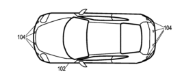
도 1은 초음파 센서(ultrasonic sensor)가 장착된 예시적인 차량의 부감도(overhead view)이다.
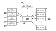
도 2는 예시적인 주행/주차 보조 시스템의 블록도이다.
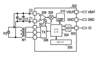
도 3은 예시적인 음향 장애물 센서의 회로 개략도이다.
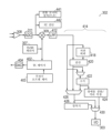
도 4는 단일-채널 감지를 갖는 예시적인 센서 제어기의 블록도이다.
도 5는 다중-채널 감지를 갖는 예시적인 센서 제어기의 블록도이다.
도 6은 인근 장애물들에 대한 제1 예시적인 감지 방법의 흐름도이다.
도 7은 인근 장애물들에 대한 제2 예시적인 감지 방법의 흐름도이다.1 is an overhead view of an exemplary vehicle equipped with an ultrasonic sensor.
2 is a block diagram of an exemplary driving/parking assistance system.
3 is a circuit schematic diagram of an exemplary acoustic obstacle sensor.
Figure 4 is a block diagram of an example sensor controller with single-channel sensing.
Figure 5 is a block diagram of an example sensor controller with multi-channel sensing.
6 is a flow diagram of a first example detection method for nearby obstacles.
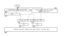
7 is a flow diagram of a second exemplary detection method for nearby obstacles.
도면들 및 다음의 상세한 설명은 본 개시내용을 제한하지 않으며, 오히려, 그들은 청구범위 언어의 범주 내에 포함되는 모든 수정들, 등가물들, 및 대안들을 이해하기 위한 토대를 당업자에게 제공한다는 것을 이해하여야 한다. 초음파 센서들이 설명의 맥락을 제공하는 데 사용되지만, 원리들은 수중 음파 시스템들, 레이더 시스템들, 및 사실상 펄스-에코 감지 기술들을 이용하는 임의의 시스템들에 적용될 수 있다.It is to be understood that the drawings and the following detailed description do not limit the disclosure, but rather, they provide a foundation for those skilled in the art to understand all modifications, equivalents, and alternatives included within the scope of the claim language. . Although ultrasonic sensors are used to provide context for explanation, the principles can be applied to sonar systems, radar systems, and virtually any system that utilizes pulse-echo sensing techniques.
예시적인 사용 맥락으로서, 도 1은 한 세트의 초음파 센서들(104)이 장착된 차량(102)을 도시한다. 센서 배열 내의 센서들의 개수 및 구성은 변화하고, 블라인드 스폿(blind-spot) 검출기들의 경우 각각의 측면 상에 추가적인 센서들을 갖고서 각각의 범퍼 상에 6개의 센서들을 갖는 것은 특이한 일이 아닐 것이다. 차량은, 잠재적으로 개별 측정들뿐만 아니라 협력(예컨대, 삼각 측량, 다중 수신기) 측정들을 위한 센서들을 사용하여, 다양한 검출 구역들 내의 물체들을 검출하고 그들까지의 거리들을 측정하기 위한 센서 배열을 이용할 수 있다.As an example usage context, Figure 1 shows a
초음파 센서들은 송수신기(transceiver)들이고, 이는 각각의 센서가 초음파 사운드의 버스트들을 송신하고 수신할 수 있다는 것을 의미한다. 방출된 버스트들은 물체 또는 일부 다른 형태의 음향 임피던스 부정합을 만나서 그로부터 반사될 때까지 차량으로부터 외측으로 전파된다. 반사된 버스트들은 방출된 버스트들의 "에코들"로서 차량으로 복귀한다. 방출된 버스트들과 수신된 에코들 사이의 시간은 반사 지점들까지의 거리들을 나타낸다. 많은 시스템에서, 한 번에 하나의 센서만이 송신하지만, 모든 센서는 생성되는 에코를 측정하도록 구성될 수 있다. 그러나, 다수의 동시 송신들이 직교 파형들, 비중첩 검출 구역들로의 송신들, 또는 상이한 송신기들로부터의 임의의 에코들의 스크리닝을 가능하게 하는 시그니처(signature)들을 갖는 송신들의 사용을 통해 지원될 수 있다.Ultrasonic sensors are transceivers, which means that each sensor can transmit and receive bursts of ultrasonic sound. The emitted bursts propagate outward from the vehicle until they encounter an object or some other type of acoustic impedance mismatch and are reflected therefrom. The reflected bursts return to the vehicle as “echoes” of the emitted bursts. The time between emitted bursts and received echoes represents the distances to reflection points. In many systems, only one sensor transmits at a time, but all sensors can be configured to measure the echoes they produce. However, multiple simultaneous transmissions can be supported through the use of orthogonal waveforms, transmissions with non-overlapping detection zones, or transmissions with signatures that enable screening of arbitrary echoes from different transmitters. there is.
다양한 구현예들에서, 처프-변조된 신호들, 예를 들어 선형 주파수 변조된("LFM") 처프가 사용된다. 처프는 송신 동안 주파수를 변경하는 펄스이다. 업 처프(up-chirp)는 송신 동안 주파수를 증가시키는 처프이고, 다운 처프(down-chirp)는 송신 동안 주파수를 감소시키는 처프이다. 명확성을 위해, 본 명세서에 사용된 예들은 선형 증가 또는 감소를 고려할 것이지만, 다양한 실시예들에서 증가 또는 감소는 선형이 아니다. 처프의 에코는 많은 또는 임의의 상관 잡음의 도입이 없이 상관기에서 압축될 수 있다. 그와 같이, 에코의 피크 검출은 시간 분해능을 감소시키지 않고서 용이하게 된다. 추가적으로, LFM 처프들은 상관 잡음의 임의의 증가 없이, 또는 최소의 증가를 가지고 도플러 주파수 시프트를 견딘다. LFM 처프들은 센서 시스템의 감지 범위에 위치된 장애물 또는 물체까지의 거리를 측정하기 위한 송신 펄스들로서 사용될 수 있다.In various implementations, chirp-modulated signals are used, such as linear frequency modulated (“LFM”) chirps. Chirps are pulses that change frequency during transmission. An up-chirp is a chirp that increases the frequency during transmission, and a down-chirp is a chirp that decreases the frequency during transmission. For clarity, the examples used herein will consider linear increases or decreases, but in various embodiments the increases or decreases are not linear. The echo of the chirp can be compressed in the correlator without introducing much or any correlation noise. As such, peak detection of echoes is facilitated without reducing temporal resolution. Additionally, LFM chirps tolerate Doppler frequency shift without any or minimal increase in correlated noise. LFM chirps can be used as transmit pulses to measure the distance to an obstacle or object located in the detection range of the sensor system.
다른 구현예들에서, 진폭 변조(amplitude-modulated, AM) 신호들, 예를 들어 고정 주파수 캐리어의 형상화된 펄스가 사용된다. AM 시그널링 모드는 더 짧은 버스트들(예컨대, 200 내지 300 마이크로초 정도)의 사용을 가능하게 하여, 송신 시간을 감소시키고 인근 장애물들에 대한 감도를 증가시킬 수 있다. 다른 구현예들은 변조된 캐리어들을 갖는 펄스들, 예컨대 이진 위상 시프트 키잉(BPSK)으로 변조된 펄스들을 이용할 수 있다. 명확성을 위해, 본 명세서에서 사용되는 용어 "버스트"는 AM(고정된 주파수), BPSK(변조됨), 또는 처프(스위핑된 주파수) 펄스를 의미하며, 이는 압전 소자 또는 다른 음향 트랜스듀서를 구동함으로써 생성된 일련의 버스트들 중 하나일 수 있다. 처프 변조된 펄스들은 전형적인 AM 펄스보다 더 긴 지속 시간을 가질 수 있으며, 예를 들어 1 밀리초 초과, 예컨대 2 내지 3 밀리초 범위일 수 있다. 여기서, 버스트 길이들은 변경될 수 있으며, 더 짧은 버스트들은 인근 장애물들의 검출을 용이하게 하는데 사용될 수 있고, 더 긴 버스트들은 더 먼 장애물들에 대한 버스트 에너지(및 에코 에너지)를 증가시키는 데 사용될 수 있음에 유의한다. 인근 장애물들을 검출하기 위한 버스트 길이들은 더 먼 장애물들에 사용되는 버스트 길이들의 절반 또는 아마도 1/4일 수 있다. 센서는 상이한 검출 거리들에 대해 모드들 사이에서 스위칭될 수 있다.In other implementations, amplitude-modulated (AM) signals are used, for example shaped pulses of a fixed frequency carrier. AM signaling mode allows the use of shorter bursts (eg, on the order of 200 to 300 microseconds), which can reduce transmission time and increase sensitivity to nearby obstacles. Other implementations may use pulses with modulated carriers, such as pulses modulated with binary phase shift keying (BPSK). For clarity, the term “burst” as used herein refers to an AM (fixed frequency), BPSK (modulated), or chirp (sweeped frequency) pulse, which is generated by driving a piezoelectric element or other acoustic transducer. It may be one of a series of bursts generated. Chirp modulated pulses may have a longer duration than typical AM pulses, for example greater than 1 millisecond, such as in the range of 2 to 3 milliseconds. Here, burst lengths can be varied, with shorter bursts being used to facilitate detection of nearby obstacles and longer bursts being used to increase burst energy (and echo energy) for more distant obstacles. Pay attention to Burst lengths for detecting nearby obstacles may be half or perhaps a quarter of the burst lengths used for more distant obstacles. The sensor can be switched between modes for different detection distances.
일련의 처프-변조된 펄스들의 특성 주파수(예컨대, 시작 주파수 또는 동등하게, 중심 또는 종료 주파수)를 체계적으로 변경하는 것은 특히 유용한 것으로 여겨지지만, 그러한 주파수 변동은 또한 일련의 AM 펄스들의 캐리어 주파수에 적용될 수 있다. 주파수 변동은 각각의 펄스에 대해 공칭 특성 주파수(예컨대, 공칭 시작 주파수 또는 공칭 캐리어 주파수)로부터의 주파수 변위로서 표현될 수 있다.It is believed to be particularly useful to systematically vary the characteristic frequency (e.g., start frequency or, equivalently, center or end frequency) of the series of chirp-modulated pulses, but such frequency variation may also apply to the carrier frequency of the series of AM pulses. You can. The frequency variation can be expressed for each pulse as a frequency displacement from a nominal characteristic frequency (eg, nominal start frequency or nominal carrier frequency).
도 2는 성형 토폴로지(star topology)의 중심으로서 다양한 초음파 센서(204)에 커플링된 전자 제어 유닛(electronic control unit, ECU)(202)을 도시한다. 물론, 직렬, 병렬 및 계층적(트리) 토폴로지들을 포함한 다른 토폴로지들이 또한 본 명세서에 개시된 원리에 따라 사용하기에 적합하며 고려된다. 자동화된 주차 또는 주행 보조를 제공하기 위해, ECU(202)는 턴-신호 액추에이터(turn-signal actuator)(206), 조향 액추에이터(steering actuator)(208), 제동 액추에이터(braking actuator)(210), 및 스로틀 액추에이터(throttle actuator)(212)와 같은 액추에이터들의 세트에 추가로 접속될 수 있다. ECU(202)는 사용자 입력을 받아들이고 다양한 측정치들 및 시스템 상태의 디스플레이를 제공하기 위해 사용자-상호작용 인터페이스(214)에 추가로 커플링될 수 있다. 인터페이스, 센서들, 및 액추에이터들을 사용하여, ECU(202)는 자동화된 주차, 보조 주차, 차선 변경 보조, 장애물 및 사각 지대 검출, 및 다른 바람직한 특징들을 제공할 수 있다.Figure 2 shows an electronic control unit (ECU) 202 coupled to various
하나의 잠재적인 센서 구성이 이제 도 3을 참조하여 설명된다. 도시된 센서 구성은 DSI3 통신 및 전력 공급 장치 표준을 이용하지만, LIN, CAN, 및 SENT 표준들에서 제공되는 것들과 같은 다른 통신 기술들이 또한 적합할 것이고, 본 명세서에 개시된 원리들에 따른 사용을 위해 고려된다. 도 3의 구현예에 도시된 2개의 전력 단자들(Vbat 및 GND) 이외에, 각각의 예시적인 초음파 센서들은 단일 입력/출력("I/O" 또는 "IO") 라인에 의해서만 ECU(202)에 접속된다. I/O 라인은, 그것이 ECU(202)에 의해 또는 센서 제어기(302)에 의해 능동적으로 로우(low) 상태("어써트(asserted)" 상태)로 구동되지 않을 때, 풀업 저항기(pull-up resistor)에 의해 공급 전압으로 바이어싱될 수 있다("디어써트(de-asserted)" 상태). 통신 프로토콜은 임의의 주어진 시간에 I/O 라인을 어써트하는 2개의 제어기들 중 하나(ECU(202) 또는 센서 제어기(302))만을 갖도록 설계된다.One potential sensor configuration is now described with reference to FIG. 3 . The sensor configuration shown utilizes the DSI3 communication and power supply standard, but other communication technologies such as those provided in the LIN, CAN, and SENT standards would also be suitable and for use in accordance with the principles disclosed herein. is considered. Other than the two power terminals (Vbat and GND) shown in the implementation of FIG. 3, each example ultrasonic sensor is connected to
센서 제어기(302)는, 역행 모드(recessive mode)에 놓여 있을 때는 ECU(202)에 의한 어써션(assertion)을 위해 I/O 라인을 모니터링하고, 우위 모드(dominant mode)에 놓여 있을 때는 I/O 라인의 상태를 구동하는 I/O 인터페이스(303)를 포함한다. ECU는 I/O 라인을 어써트함으로써 센서로 커맨드를 통신하며, 상이한 커맨드들이 상이한 길이들의 어써션들에 의해 표현된다. 커맨드들은 "전송 및 수신" 커맨드, "수신 전용" 커맨드, 및 "데이터 모드" 커맨드를 포함할 수 있다.The
센서 제어기(302)는, ECU로부터의 커맨드를 파싱(parse)하고, 초음파 버스트들의 송신 및 수신을 포함하는 적절한 동작들을 실행하기 위해 비휘발성 메모리(305)에 저장된 파라미터들 및 펌웨어에 따라 동작하는 코어 로직(304)을 포함한다. 초음파 버스트를 송신하기 위해, 코어 로직(304)은 송신기(306)에 커플링되는데, 이는 전압 제어형 발진기(307)로부터의 적합하게 변조된 로컬 발진기 신호로, 센서 제어기(302) 상의 송신 단자들의 세트를 구동한다. 송신기 단자들은 변압기(M1)를 통해 압전 소자(piezoelectric element, PZ)에 커플링된다. 변압기(M1)는 센서 제어기로부터의 전압(예컨대, 12 볼트)을 압전 소자를 구동하기 위한 적합한 레벨(예컨대, 수십 볼트)로 승압한다. 압전 소자(PZ)는 병렬 커패시터(C3)에 의해 원하는 값(예컨대, 48 ㎑)으로 튜닝되는 공진 주파수를 갖고, 병렬 저항기(R1)에 의해 튜닝되는 공진 품질 인자(Q)를 갖는다. 튜닝 커패시터 및 튜닝 저항기의 하나의 예시적인 목적은 병렬 공진 주파수를 압전 소자의 직렬 공진 주파수에 가깝게 튜닝하는 것이다.
본 명세서에 사용된 바와 같이, 용어 "압전 트랜스듀서"는 압전 소자뿐만 아니라 압전 소자를 튜닝하고, 구동하고, 감지하기 위한 지원 회로 소자들을 포함한다. 예시적인 구현예에서, 이들 지원 소자들은 변압기(M1), 튜닝 저항기 및 튜닝 커패시터, 및 DC 격리 커패시터(DC-isolation capacitor)들이다. 선택적으로, 송신기(306) 및 증폭기(308)의 출력 및 입력 커패시턴스는 각각, 트랜스듀서의 일부인 것으로 간주되는 지원 회로 소자들의 기생 특성들로서 또한 포함될 수 있다. 예시된 구현예에서, 한 쌍의 DC 격리 커패시터들(C1, C2)은 압전 소자(PZ)를 센서 제어기의 수신 단자들의 쌍에 커플링하여 고전압들로부터 보호한다. 수신 단자들 상의 내부 전압 클램프들로 추가 보호가 제공된다. 그러한 보호는, 압전 소자가 송신 중일 때 간격을 위해 요구될 수 있다.As used herein, the term “piezoelectric transducer” includes a piezoelectric element as well as supporting circuit elements for tuning, driving, and sensing the piezoelectric element. In an example implementation, these support elements are transformer M1, tuning resistor and tuning capacitor, and DC-isolation capacitors. Optionally, the output and input capacitances of
I/O 라인을 통해 수신된 커맨드들은 코어 로직(304)을 트리거하여 송신기 및 수신기를 동작시키고, 본 명세서에서 통신 버스로도 지칭되는 I/O 라인을 통해 측정 결과들을 ECU(202)에 제공한다. 측정 결과들은 또한 본 명세서에서 출력 데이터로도 지칭된다. 코어 로직(304)은, 초음파 버스트를 송신하는 동안 공급 전압 "미만 전압" 또는 "초과 전압"을 갖는 것과 같은 다른 센서 상태들, 송신기의 열 차단(thermal shutdown), 하드웨어 오류, 불완전한 파워-온 리셋 등을 모니터링할 수 있다. 코어 로직(304)은 다수의 그러한 트랜스듀서 결함 상태들 및 에러 상태들을 검출하고 분류하여, 적절한 결함 코드들을 내부 레지스터들 또는 비휘발성 메모리(305)에 저장할 수 있다.Commands received over the I/O lines trigger the core logic (304) to operate the transmitter and receiver and provide measurement results to the ECU (202) over the I/O lines, also referred to herein as a communication bus. The measurement results are also referred to herein as output data. The core logic (304) may monitor other sensor conditions such as having a supply voltage “under voltage” or “over voltage” while transmitting an ultrasonic burst, thermal shutdown of the transmitter, hardware errors, incomplete power-on reset, etc. The core logic (304) may detect and classify a number of such transducer fault conditions and error conditions and store appropriate fault codes in internal registers or nonvolatile memory (305).
수신된 에코 신호들이 전형적으로 밀리볼트 또는 마이크로볼트 범위에 있기 때문에, 프론트 엔드 증폭기(308)는 수신 단자들로부터의 신호를 버퍼링하고 증폭시킨다. 후속적으로, 수신된 에코 신호들은 아날로그-디지털 변환기(ADC)에 의해 프로세싱되고, 디지털 믹서(309)에 의해 하향변환된다. 믹서(309)는, 디지털 신호 프로세서(DSP)(310)에 의한 추가 필터링 및 프로세싱을 위해, 증폭되고 디지털화된 수신 신호를 로컬 발진기 신호와 곱하여 변조된 신호를 기저대역으로 하향변환한다. 일 구현예에서, 믹서(309)는 위상 내/직교(I/Q) 디지털 믹서로서 제로 중간 주파수(Zero Intermediate Frequency, ZIF) IQ 데이터를 그의 출력으로서 제공하는 것이다. (용어 "ZIF"가 본 명세서에서 사용되지만, 하향변환된 신호는 실제로 낮은 중간 주파수 또는 "근거리 기저대역" 신호일 수 있다.)Since the received echo signals are typically in the millivolt or microvolt range, the
DSP(310)는 버스트의 송신 동안 압전 트랜스듀서를 모니터링하고, 임의의 에코들을 검출하고 ToF(time-of-flight), 지속기간, 및 피크 진폭과 같은 그들의 파라미터들을 측정하기 위한 프로그래밍가능 방법들을 적용한다. 그러한 방법들은 임계치 비교들, 최소 간격들, 피크 검출들, 제로 크로싱(zero-crossing) 검출 및 카운팅(counting), 잡음 레벨 결정들, 및 신뢰도와 정확도 향상을 위해 맞추어진 다른 맞춤형 기법들을 이용할 수 있다. 특히, 피크 검출 프로세스 자체는 변형들을 가지며, 일부 변형들은 상승 에지 검출, 하강 에지 검출, 또는 피크 최대치의 검출을 수행한다. DSP(310)는 공진 주파수 및 품질 인자와 같은 트랜스듀서의 특성들을 분석하기 위해 증폭된 수신 신호를 추가로 프로세싱할 수 있고, 트랜스듀서 결함 상태들을 추가로 검출할 수 있다.
위에서 언급된 바와 같이, 믹서(309)는 일 구현예에서 직교상 믹서이다. 이러한 I/Q 디지털 믹서(309)는 아날로그-디지털 변환기(도시되지 않음)의 출력에 접속된 입력, 혼합 신호(FTX)를 수신하기 위한 입력, 및 복소 평면에서 음향 트랜스듀서로부터의 신호 입력의 진폭 및 위상에 대응하는 위상 내 신호 및 직교 신호를 각각 제공하기 위한 제1 및 제2 출력들을 갖는다. DSP(310)는 ZIF-IQ 신호에 대해 동작하기 위해 메모리에 저장된 필터 계수들을 취출하고 사용하도록 구성되는 하나 이상의 디지털 필터들을 포함할 수 있다. 보다 구체적으로, 디지털 필터들은 저역 통과 필터들 및 상관기들을 포함할 수 있다. DSP(310)는, 위상 미분, 크기 측정, 다운 샘플링, 진폭 스케일링(감쇠 제어), 잡음 억제, 피크 검출, 잔향(reverberation) 모니터링, 및 트랜스듀서 진단을 포함하는 다른 동작들을 위한 프로그래밍가능 모듈들 또는 전용 회로부, 및 호스트 통신들을 위한 인터페이스를 포함할 수 있다.As mentioned above,
도 4는 예시적인 단일 채널 구현예에서 제어기(302)의 블록도이다. 인근 장애물 검출을 위한 프로세싱은 전적으로 제어기(302)에서 수행될 수 있거나, 또는 도 2 및 도 3을 참조하여 이전에 기술된 바와 같이 통신 버스를 통해 특정 데이터를 수신하는 ECU 또는 호스트 프로세서와 공유되거나 그로 위임될 수 있다. 간략함을 위해, 도 4는 예를 들어 전력전자 섹션과 같은 제어기(302)의 모든 특징부들을 도시하지는 않는다.Figure 4 is a block diagram of
도 3을 참조하여 위에서 논의된 바와 같이, 제어기(302)는 수신기 및 송신기 둘 뿐만 아니라 수신된 응답의 출력 데이터로의 변환을 위해 수신기에 커플링된 프로세싱 회로를 포함한다. 프로세싱 회로는 디지털 신호 프로세서(DSP) 내의 애플리케이션 특정 회로부 또는 프로그래밍가능 모듈들로서 구현될 수 있다.As discussed above with reference to Figure 3,
캐리어 주파수 신호를 생성하기 위한 발진기(307)가 송신 제어기(402) 및 믹서(309)에 커플링된다. 발진기(307)는 예컨대, 50 ㎑의 공칭 캐리어 주파수를 제공할 수 있다. TX 제어기(402)는 캐리어 주파수 신호를 사용하여 일련의 AM 또는 처프 버스트 신호들을 도출하여, 주파수 오프셋 제어기(403)에 의해 특정된 바와 같이 주파수 오프셋을 적용한다. 예시된 단일 채널 구현예에서, 비-오프셋 처프 버스트 신호들은 캐리어 주파수의 7 ㎑ 아래로부터 캐리어 주파수의 7 ㎑ 위까지 상향으로 주파수 스위핑될 수 있다. 대안적으로 업 처프 대신에 다운 처프가 이용될 수 있다. 디지털-아날로그 변환기(404)는 디지털 음향 버스트들을 음향 트랜스듀서를 위한 아날로그 구동 신호로 변환한다.An
주파수 오프셋 제어기(403)는 디지털 버스트 신호들의 특성 주파수(예컨대, AM 버스트들에 대한 캐리어 주파수, 또는 처프 버스트들에 대한 시작 주파수)에 주파수 변위들을 적용하도록 구성된다. 그러한 주파수 변위들은 예를 들어 200 내지 2000 ㎐의 범위, 바람직하게는 300 내지 1200 ㎐의 범위, 예컨대 600 내지 1000 ㎐, 또는 800 ㎐, 또는 900 ㎐이다. 특성 주파수의 변위들은 음향 버스트들의 에코들에서 대응하는 도플러-유사 주파수 시프트들을 야기한다.Frequency offset
각각의 음향 버스트 이후에, 제어기(302)는 프론트 엔드 증폭기(308)에 의해 선택적으로 증폭된 음향 트랜스듀서(PZ)(도 3)의 응답을 표현하는 입력 신호를 수신한다. 아날로그-디지털 변환기(ADC)(311)는 비교적 높은 샘플링 레이트, 예컨대, 400 ㎑에서 입력 신호를 디지털화한다. 진단 블록(442)은 단독으로 또는 잔향 모니터링 블록(441)과 조합하여, 디지털화된 응답 신호를 분석하여 임의의 트랜스듀서 결함 상태들을 검출 및 진단한다. 일부 결함 상태들은 예컨대 과도하게 짧은 잔향 기간들(이는 접속해제되거나 결함이 있는 트랜스듀서, 억제된 진동 등으로 인한 것일 수 있음)에 의해 나타날 수 있는 한편, 다른 것들은 과도하게 긴 잔향 기간(결함 있는 장착, 부적절한 댐핑 저항 등)에 의해 나타날 수 있다. 진단 블록(442)은 다수의 이러한 트랜스듀서 결함 상태들을 검출 및 분류하여 내부 레지스터들에 적절한 결함 코드들을 저장할 수 있으며, 이들은 그로부터 ECU로 통신될 수 있다. 잔향 모니터링 블록(441)은 트랜스듀서 잔향 기간의 종료를 검출하고 시그널링하며, 선택적으로 에코 검출을 위한 신호 프로세싱을 개시한다.After each acoustic burst,
디지털화된 응답은 후속적으로 디지털 I/Q 믹서(309)에서 하향변환된다. 디지털 I/Q 믹서(309)는 입력 신호를 합 주파수(sum frequency) 및 차 주파수(difference frequency)로 시프트하고, 여기서 차 주파수는 기저대역(제로 중간 주파수) 근처에 있다. I/Q 디지털 믹서(309)는 수신된 신호의 위상 내 성분 및 직교 성분 둘 모두를 갖는 기저대역 신호를 출력한다. 저역 통과 필터(LPF)(412)는 하향변환된 응답으로부터 특정 잡음 성분들(합 주파수에서의 입력 신호 이미지를 포함함)을 제거하기 위해 믹서(309)의 하류측에 배치된다. 필터링된 신호는 본 명세서에서 ZIF IQ 데이터로 지칭될 수 있다.The digitized response is subsequently downconverted in a digital I/
예시적인 제어기(302)는 프로세싱 회로부(414)를 포함하며, 원하는 경우, 그 대부분은 (멀티플렉서들(426, 430)을 통해) 바이패스되어 오프 칩으로 ZIF IQ 데이터를 I/O 인터페이스(303)를 통해 전달하여 ECU 또는 호스트 프로세서가 신호들을 프로세스할 수 있게, 예컨대, 반사들의 이동 시간 및 따라서 장애물들까지의 거리를 결정하기 위해 신호에서의 피크들의 타이밍을 분석할 수 있게 할 수 있다. 피크 크기 및 폭이 또한 유의성을 결정하기 위해 분석될 수 있다. I/O 대역폭 요건들을 감소시키기 위해, ZIF IQ 데이터를 표현하는 데 필요한 비트들의 수를 감소시키기 위해 또는 IQ 컴포넌트 데이터를 신호 크기로 변환하는 크기 블록(422)의 출력을 표현하기 위해 압축기 블록(428)이 포함될 수 있다. (크기 블록(422)은 위상 내 성분 신호를 제곱하고, 직교 위상 성분 신호를 제곱하고, 그 둘을 합산하고, 선택적으로 합산된 신호의 제곱근 또는 로그를 취함으로써 동작할 수 있다.) 대역폭 요건들을 더욱 추가로 감소시키기 위해, 제어기(302)는 검출 블록(424)으로 온-칩 프로세싱을 수행할 수 있고, 이는 피크 검출 및 거리 추정 프로세싱을 수행할 수 있다.The
발명의 배경이 되는 기술에서 언급된 바와 같이, 센서들은 트랜스듀서의 잔류 잔향뿐만 아니라 인근 장애물들로부터 에코들을 마스킹하는 구조적 잡음을 겪는다. 저자들은 이러한 효과들이 지극히 온도 의존적이며, 노화로 인한 것들을 포함한 센서 컴포넌트들의 다른 파라미터 변형들을 겪는다는 것을 발견했다. 그러나, 펜더들 또는 다른 위에 놓인 표면 뒤에 장착된 "은닉된" 센서의 경우, 이러한 효과들은 또한 음향 버스트 특성 주파수와 대체로 독립적인 것으로 밝혀졌다. 에코들이 특성 주파수에 민감한 반면 구조적 잡음은 그렇지 않기 때문에, 인근 장애물들의 신뢰할 수 있는 검출을 제공하는 센서의 능력은 상이한 특성 주파수들을 갖는 음향 버스트들에 대한 트랜스듀서 응답들 사이의 차이를 결정함으로써 향상될 수 있다.As mentioned in the technology behind the invention, sensors suffer from residual reverberation of the transducer as well as structural noise that masks echoes from nearby obstacles. The authors found that these effects are extremely temperature dependent and that sensor components undergo variations in different parameters, including those due to aging. However, for "hidden" sensors mounted behind fenders or other overlying surfaces, these effects have also been found to be largely independent of the acoustic burst characteristic frequency. Because echoes are sensitive to characteristic frequencies while structured noise is not, the ability of a sensor to provide reliable detection of nearby obstacles can be improved by determining the difference between transducer responses to acoustic bursts with different characteristic frequencies. You can.
따라서, 예시된 제어기(302)는 각각의 버스트로부터 ZIF IQ 데이터를 캡처하기 위해 프로세싱 회로부의 각각의 분기에서 지연 버퍼(418)를 포함하여, 상이한 주파수 오프셋들을 갖는 인접 버스트들로부터의 ZIF IQ 데이터 사이의 차이를 결정하기 위해 이전 버스트로부터의 데이터를 감산 소자(420)에 대해 이용가능하게 한다. 주파수에 민감하지 않으므로, 구조적 잡음이 실질적으로 제거되는 반면, 에코들은 향상된다. 차이 신호는 오프-칩 프로세싱을 위해 압축기 또는 I/O 인터페이스로 전달될 수 있거나, 또는 인근 장애물들의 온-칩 검출을 위해 크기 블록(422) 및 검출 블록(424)으로 전달될 수 있다.Accordingly, the illustrated
도 5는, 프로세싱 회로부가 각각의 채널에 대해 분기(414, 415)를 갖는 예시적인 다중-채널 구현예에서의 제어기(302)의 블록도이다. 송신 제어기(402)는 캐리어 주파수의 7 ㎑ 아래로부터 캐리어 주파수의 1 ㎑ 아래로 상향으로 주파수 스위핑된 하부 채널 처프, 및 캐리어 주파수의 1 ㎑ 위로부터 캐리어 주파수의 7 ㎑ 위로 주파수 스위핑된 상부 채널 처프를 생성하도록 구성될 수 있다. 대안적으로 업 처프들 중 임의의 것 또는 전부 대신에 다운 처프가 이용될 수 있다. 시스템 구성에 따라, TX 제어기(402)는 단지 하나의 채널에서만 동작할 수 있거나, 상위 채널과 하위 채널을 교번하거나 그렇지 않으면 둘 모두를 이용할 수 있다. 각각의 분기에는 ZIF IQ 데이터의 신호 스펙트럼을 그 채널의 주파수 범위로 제한하기 위해 대응하는 채널 필터(416, 417)가 제공될 수 있다. 이어서, 이전에 설명된 프로세싱 단계들은 대응하는 채널 내에 존재하는 ZIF IQ 데이터 에너지의 그 부분에 대해 수행될 수 있다. 필터들은 각각 메모리로부터 취출가능한 복소 값 계수들을 갖는 프로그래밍가능 유한 임펄스 응답 필터(FIR)의 형태를 취할 수 있다. 여기에 도시되지 않았지만, 프로세싱 회로부는 신호 대 잡음비를 향상시키기 위해 상관 또는 매칭 응답 필터링을 제공하기 위해 추가 필터들로 구성될 수 있다.FIG. 5 is a block diagram of
여기서, 단일 채널 구현예(도 4)는 인근 장애물에 대한 민감도를 최대화하고 따라서 그러한 장애물을 검출하고 그러한 장애물이 검출되었음을 나타내도록 경보를 제공하거나 플래그를 설정하는 데 특히 매우 적합할 수 있다는 점에 유의한다. 이러한 구현예는 심지어 트랜스듀서로부터 본질적으로 0 cm가 될 정도로 가까운 인근 장애물들을 검출하도록 동작하며, 생성된 검출 플래그는 0 cm 플래그로 지칭될 수 있다. 다중-채널 구현예(도 5)는 일부 검출 민감도를 잃을 수 있어 신뢰성 있는 검출이 되려면 트랜스듀서로부터 더 큰 최소 거리를 요구할 수 있지만, 그 대신 다중-채널 측정치들은 존재하는 임의의 인근 장애물들에 대한 거리의 더 정확한 결정을 제공할 수 있다.Note here that the single channel implementation (Figure 4) maximizes sensitivity to nearby obstacles and may therefore be particularly well suited to detecting such obstacles and providing an alert or setting a flag to indicate that such an obstacle has been detected. do. This implementation operates to detect nearby obstacles even as close as essentially 0 cm from the transducer, and the detection flag generated may be referred to as the 0 cm flag. Multi-channel implementations (FIG. 5) may lose some detection sensitivity and may require a greater minimum distance from the transducer for reliable detection, but multi-channel measurements may in return be more accurate for any nearby obstacles present. Can provide more accurate determination of distance.
도 6은 향상된 근접 감지를 제공하기 위해 트랜스듀서의 구조적 잡음의 특성 주파수 불감도를 활용하는 제1 예시적인 감지 방법의 흐름도이다. 방법은 ECU에 의해 구현되거나, 센서 제어기에 의해 구현되거나, 또는 이 둘에 걸쳐 분산될 수 있지만, 이하의 설명은 설명의 목적을 위해 제어기를 사용한다.FIG. 6 is a flow diagram of a first exemplary sensing method that utilizes the characteristic frequency insensitivity of the transducer's structured noise to provide improved proximity sensing. The method may be implemented by an ECU, by a sensor controller, or distributed across both, but the following description uses the controller for illustrative purposes.
블록(502)에서, 제어기는 임의의 주파수 오프셋 없이 송신된 제1 음향 버스트에 대한 응답을 획득하고, 이어서 블록(504)에서, 주파수 오프셋, 예컨대 900 ㎐로 전송된 제2 음향 버스트에 대한 응답을 획득한다. 일부 구현예들에서, 제어기는 트랜스듀서의 응답이 주파수 오프셋에 민감한 경우 주파수 오프셋으로 응답을 스케일링한다. 제어기는 블록들(502, 504)을 반복하여 교번하는 주파수 오프셋들을 갖는 일련의 응답들을 획득한다. 블록들(510, 511)은 각각 블록들(502, 504)에서 획득된 응답들을 버퍼링하여, 이들을 나중의 응답들로부터의 감산에 이용가능하게 한다.At
블록(520)에서, 제어기는 주파수 오프셋이 없는 음향 버스트에 대한 현재 응답으로부터 주파수 오프셋이 없는 음향 버스트에 대한 이전 응답을 감산한다. 두 버스트들 둘 모두가 동일한 주파수 오프셋을 갖기 때문에(즉, 주파수 오프셋이 없음), 블록(520)의 출력은 정렬된 주파수 차이 신호로 지칭된다. 블록(521)에서, 제어기는 주파수 오프셋이 없는 음향 버스트에 대한 현재 응답으로부터 주파수 오프셋을 갖는 이전 음향 버스트로부터의 응답 신호를 감산한다. 버스트들이 상이한 주파수 오프셋들을 갖기 때문에, 이러한 차이 신호는 오프셋 주파수 차이 신호로 지칭된다. 더 공식적으로, 용어 "오프셋 주파수 차이 신호"는 본 명세서에서 오프셋 특성 주파수들을 갖는 인접한 송신 버스트들로부터 획득된 ZIF IQ 신호들 사이의 차이를 지칭하기 위해 사용된다. 블록들(522, 523)에서, 제어기는 유사하게, 현재 응답 신호로서, 블록(504)으로부터의 응답을 사용하여 오프셋 주파수 및 정렬된 주파수 차이 신호들을 생성하여, 제어기가 각각의 측정된 응답으로부터 오프셋 주파수 차이 및 정렬된 주파수 차이 신호를 결정하게 한다.At
구조적 잡음이 주파수 오프셋에 민감하지 않기 때문에, 이는 오프셋 주파수 및 정렬된 주파수 차이 신호들에 존재하지 않는다. (온도 및 다른 인자들에 대한 구조적 잡음 감도는 인접 음향 버스트들의 사용에 의해 무효화되는데, 그 이유는 온도 및 다른 인자들이 버스트들 사이의 작은 간격에서 유의한 변화를 갖지 않기 때문이다.) 그러나, 임의의 인근 장애물로부터의 에코들은 주파수 오프셋에 민감하여, 장애물이 주파수 오프셋의 효과를 무효화하는 도플러 시프트를 생성하는 방식으로 이동하지 않는 한 오프셋 주파수 차이 신호가 향상되게 한다. 반대로, 장애물이 이동하고 있지 않는 한, 임의의 인근 장애물들의 에코들은 정렬된 주파수 차이 신호에 존재하지 않아야 한다. 이어서, 예방책으로서, 오프셋 주파수 차이 신호 및 정렬된 주파수 차이 신호는 (예컨대, 15 cm 이내, 또는 선택적으로 10 cm 이내, 5 cm 이내, 3 cm 이내, 또는 2 cm 이내에) 인근 장애물이 존재하는지 여부를 결정하기 위해 평가될 수 있다.Since structured noise is insensitive to frequency offset, it is not present in the offset frequency and aligned frequency difference signals. (Structured noise sensitivity to temperature and other factors is negated by the use of adjacent acoustic bursts, since temperature and other factors do not vary significantly at small intervals between bursts.) However, any Echoes from nearby obstacles are sensitive to frequency offset, causing the offset frequency difference signal to be enhanced unless the obstacle moves in a way that creates a Doppler shift that negates the effect of the frequency offset. Conversely, unless the obstacle is moving, echoes of any nearby obstacles should not be present in the aligned frequency difference signal. Then, as a precaution, the offset frequency difference signal and the aligned frequency difference signal determine whether nearby obstacles are present (e.g., within 15 cm, or optionally within 10 cm, within 5 cm, within 3 cm, or within 2 cm). can be evaluated to make a decision.
따라서, 블록들(530 내지 533)에서, 제어기는 다양한 차이 신호들의 IQ 성분들을 크기 신호들로 변환하고, 블록(540)에서, 제어기는 크기 신호들을 임계치와 비교하여 장애물들로부터 에코들을 나타내는 임의의 피크들을 검출한다. 임계치는 더 먼 거리들로부터 복귀하는 에코들의 예상된 감쇠를 고려하기 위해 경과 시간에 따라 달라질 수 있다. 너무 가까운 장애물들을 나타내는 임의의 피크들을 검출할 때, 제어기는 ECU 또는 드라이버에 경보를 제공할 수 있다. 일부 구현예들에서, 제어기는 각각의 피크와 연관된 장애물 거리를 결정한다.Accordingly, at blocks 530-533, the controller converts the IQ components of the various difference signals into magnitude signals, and at
도 5의 예시적인 감지 방법은 비인접 음향 버스트들로부터 정렬된 주파수 차이 신호들을 도출한다. 도 7은 주어진 인접 음향 버스트들의 쌍으로부터 오프셋 주파수 차이 신호들 및 정렬된 주파수 차이 신호들을 도출하는 제2 예시적인 방법을 제공한다. 제1 방법에서와 같이, 제어기는 블록(502)에서 임의의 주파수 오프셋 없이 송신된 제1 음향 버스트에 대한 응답을 획득하고, 이어서 블록(704)에서, 주파수 오프셋, 예컨대 900 ㎐로 전송된 제2 음향 버스트에 대한 응답을 획득한다. 추가적으로 블록(704)에서, 제어기는 제2 음향 버스트에 대한 보상된 응답을 획득한다. 보상된 응답은 예를 들어, 송신된 버스트의 특성 주파수와 매칭되도록 믹서(309)로 공급되는 로컬 발진기 신호를 조정하고 조정된 로컬 발진기 신호를 사용하여 하향 변환을 반복함으로써 획득될 수 있다. (대안적으로, 제2 믹서 소자는 하향 변환들이 병렬로 수행될 수 있게 하는 데 사용될 수 있다.) 제어기는, 트랜스듀서의 응답이 주파수 오프셋에 민감한 경우, 주파수 오프셋 및 보상된 응답으로 응답을 스케일링할 수 있다. 제어기는 블록들(502, 704)을 반복하여 교번하는 주파수 오프셋들을 갖는 버스트들에 대한 일련의 응답들을 획득한다.The example sensing method of FIG. 5 derives aligned frequency difference signals from non-adjacent acoustic bursts. 7 provides a second example method of deriving offset frequency difference signals and aligned frequency difference signals from a given pair of adjacent acoustic bursts. As in the first method, the controller obtains a response at
블록(510)은 블록(502)에서 획득된 비-오프셋 응답을 버퍼링하여, 블록(704)에서 획득된 응답들로부터의 감산을 위해 블록들(521, 523)에 이용가능하게 한다. 블록(521)에서, 제어기는 버퍼링된 응답 신호를 오프셋 응답 신호로부터 감산하여 오프셋 주파수 차이 신호를 획득하는 반면, 블록(523)에서, 제어기는 버퍼링된 응답 신호를 보상된 응답 신호로부터 감산하여 정렬된 주파수 차이 신호를 획득한다. 블록들(531, 533)에서, 제어기는 다양한 차이 신호들의 IQ 성분들을 크기 신호들로 변환하고, 블록(540)에서, 제어기는 크기 신호들을 임계치와 비교하여 장애물들로부터 에코들을 나타내는 임의의 피크들을 검출한다. 임계치는 더 먼 거리들로부터 복귀하는 에코들의 예상된 감쇠를 고려하기 위해 경과 시간에 따라 달라질 수 있다. 너무 가까운 장애물들을 나타내는 임의의 피크들을 검출할 때, 제어기는 ECU 또는 드라이버에 경보를 제공할 수 있다. 일부 구현예들에서, 제어기는 각각의 피크와 연관된 장애물 거리를 결정한다.Block 510 buffers the non-offset response obtained at
설명된 방법들은 단일 채널 시스템에 대한 것이다. 다중-채널 시스템에서, 프로세싱은 선택된 채널에서 수행될 수 있거나, 또는 모든 채널에서 수행되어 거리 결정 정확도를 향상시킬 수 있다. 초음파 감지의 맥락에서 설명되었지만, 개시된 기술들은 레이더 시스템들, 수중 음파 시스템들, 및 더 일반적으로는 펄스-에코 감지를 이용하는 모든 시스템들에 적용가능하다.The methods described are for single channel systems. In a multi-channel system, processing may be performed on selected channels or may be performed on all channels to improve range determination accuracy. Although described in the context of ultrasonic sensing, the disclosed techniques are applicable to radar systems, sonar systems, and more generally to all systems that utilize pulse-echo sensing.
요약하면, 예시적인 제어기가 개시되었으며, 제어기는, 제1 음향 버스트 및 제2 음향 버스트를 생성하기 위해 음향 트랜스듀서를 구동하는 송신기; 제1 음향 버스트에 대한 제1 응답 및 제2 음향 버스트에 대한 제2 응답을 감지하기 위해 음향 트랜스듀서에 커플링되는 수신기; 및 제1 응답과 제2 응답 사이의 오프셋 주파수 차이를 결정함으로써 부분적으로 제1 및 제2 응답들로부터 출력 데이터를 도출하는 프로세싱 회로를 포함하고, 제1 음향 버스트는 제1 특성 주파수를 갖고, 제2 음향 버스트는 제1 특성 주파수와는 상이한 제2 특성 주파수를 갖는다.In summary, an exemplary controller is disclosed, the controller comprising: a transmitter that drives an acoustic transducer to produce a first acoustic burst and a second acoustic burst; a receiver coupled to the acoustic transducer to sense a first response to the first acoustic burst and a second response to the second acoustic burst; and a processing circuit that derives output data from the first and second responses in part by determining an offset frequency difference between the first and second responses, wherein the first acoustic burst has a first characteristic frequency, and 2 The acoustic burst has a second characteristic frequency that is different from the first characteristic frequency.
또한, 예시적인 장애물 검출 방법이 개시되며, 방법은, 일련의 음향 버스트들에서 각각의 음향 버스트에 대한 음향 트랜스듀서의 응답을 감지하는 단계 - 일련의 음향 버스트들은 제1 음향 버스트 및 제2 음향 버스트를 포함함 -; 제1 음향 버스트에 대한 응답과 제2 음향 버스트에 대한 응답 사이의 오프셋 주파수 차이를 결정하는 단계 - 제1 음향 버스트는 제1 특성 주파수를 갖고, 제2 음향 버스트는 제1 특성 주파수와는 상이한 제2 특성 주파수를 가짐 -; 및 차이에 대해 동작하여 임의의 인근 장애물들을 검출하는 단계를 포함한다.Additionally, an exemplary obstacle detection method is disclosed, the method comprising: detecting the response of an acoustic transducer for each acoustic burst in a series of acoustic bursts, wherein the series of acoustic bursts includes a first acoustic burst and a second acoustic burst. Contains -; Determining an offset frequency difference between the response to the first acoustic burst and the response to the second acoustic burst, wherein the first acoustic burst has a first characteristic frequency, and the second acoustic burst has a second characteristic frequency that is different from the first characteristic frequency. 2 has a characteristic frequency -; and operating on the difference to detect any nearby obstacles.
또한, 예시적인 센서가 개시되며, 센서는, 음향 트랜스듀서; 및 주파수에서 교번하는 오프셋들을 갖는 일련의 음향 버스트들을 생성하고 일련의 음향 버스트들에서 각각의 음향 버스트에 대한 음향 트랜스듀서의 응답을 측정하기 위해 음향 트랜스듀서에 커플링되는 제어기를 포함하고, 제어기는 일련의 음향 버스트들에서 인접한 음향 버스트들에 대한 각각의 응답들의 쌍 사이의 오프셋 주파수 차이를 결정하도록 구성되고, 오프셋 주파수 차이는 임의의 인근 장애물들의 존재에 대한 크기 민감성을 갖는다.Additionally, exemplary sensors are disclosed, including: an acoustic transducer; and a controller coupled to the acoustic transducer to generate a series of acoustic bursts having alternating offsets in frequency and measure the response of the acoustic transducer for each acoustic burst in the series of acoustic bursts, the controller comprising: and determine an offset frequency difference between each pair of responses to adjacent acoustic bursts in a series of acoustic bursts, the offset frequency difference having magnitude sensitivity to the presence of any nearby obstacles.
전술한 제어기, 방법, 및 센서 각각은 개별적으로 또는 조합하여 사용될 수 있고, 임의의 적합한 조합으로 하기 특징들 중 하나 이상을 포함할 수 있다: 1. 송신기는 음향 트랜스듀서를 구동하여 제3 음향 버스트를 생성하도록 구성되고, 제3 음향 버스트는 제1 특성 주파수를 갖는다. 2. 수신기는 제3 음향 버스트에 대한 제3 응답을 감지하도록 구성되고, 프로세싱 회로는 제1 응답과 제3 응답 사이의 정렬된 주파수 차이를 결정하도록 구성된다. 3. 프로세싱 회로는 오프셋 주파수 차이 및/또는 정렬된 주파수 차이의 크기를 임계치와 비교하여 인근 장애물이 존재하는지 여부를 결정하도록 구성된다. 4. 프로세싱 회로는 오프셋 주파수 차이 및/또는 정렬된 주파수 차이의 크기를 임계치와 비교하여 인근 장애물로의 거리를 결정하도록 구성된다. 5. 수신기는 수신 신호를 기저대역 신호로 하향 변환하고 상기 감지의 일부로서 상관 필터를 적용하도록 구성된다. 6. 제1 및 제2 음향 버스트들은 제1 특성 주파수와 제2 특성 주파수 사이에서 교번하는 특성 주파수들을 갖는 일련의 음향 버스트들에서 인접해 있다. 7. 제1 음향 버스트 및 제2 음향 버스트 각각은, 더 먼 장애물들을 검출하기 위해 음향 트랜스듀서에 의해 생성된 다른 음향 버스트들의 50% 미만인 버스트 길이를 갖는다. 8. 각각의 음향 버스트들은 업-처프들 또는 다운-처프들이다. 9. 제어기는 다수의 별개의 주파수 대역들 각각에서 상기 오프셋 주파수 차이를 결정하도록 구성된다.Each of the foregoing controllers, methods, and sensors may be used individually or in combination, and may include one or more of the following features in any suitable combination: 1. A transmitter drives an acoustic transducer to emit a third acoustic burst. and the third acoustic burst has a first characteristic frequency. 2. The receiver is configured to detect a third response to the third acoustic burst, and the processing circuit is configured to determine an aligned frequency difference between the first response and the third response. 3. The processing circuit is configured to compare the magnitude of the offset frequency difference and/or the aligned frequency difference to a threshold to determine whether a nearby obstacle is present. 4. The processing circuit is configured to compare the magnitude of the offset frequency difference and/or the aligned frequency difference to a threshold to determine the distance to a nearby obstacle. 5. The receiver is configured to down-convert the received signal to a baseband signal and apply a correlation filter as part of the detection. 6. The first and second acoustic bursts are adjacent in a series of acoustic bursts with characteristic frequencies alternating between the first characteristic frequency and the second characteristic frequency. 7. Each of the first and second acoustic bursts has a burst length that is less than 50% of the other acoustic bursts produced by the acoustic transducer to detect more distant obstacles. 8. Each sound burst is either up-chirps or down-chirps. 9. The controller is configured to determine the offset frequency difference in each of a plurality of distinct frequency bands.
Claims (6)
상기 음향 트랜스듀서를 구동하여 제1 음향 버스트 및 제2 음향 버스트를 생성하는 송신기;
상기 제1 음향 버스트에 대한 제1 응답 및 상기 제2 음향 버스트에 대한 제2 응답을 감지하도록 상기 음향 트랜스듀서에 커플링된 수신기; 및
상기 제1 응답과 상기 제2 응답 사이의 오프셋 주파수 차이를 결정함으로써 부분적으로 상기 제1 응답 및 상기 제2 응답으로부터 출력 데이터를 도출하는 프로세싱 회로를 포함하고,
상기 제1 음향 버스트는 제1 특성 주파수를 갖고, 상기 제2 음향 버스트는 상기 제1 특성 주파수와는 상이한 제2 특성 주파수를 갖는, 제어기.A controller for an acoustic transducer, comprising:
a transmitter that drives the acoustic transducer to generate a first acoustic burst and a second acoustic burst;
a receiver coupled to the acoustic transducer to sense a first response to the first acoustic burst and a second response to the second acoustic burst; and
processing circuitry to derive output data from the first response and the second response in part by determining an offset frequency difference between the first response and the second response;
wherein the first acoustic burst has a first characteristic frequency and the second acoustic burst has a second characteristic frequency different from the first characteristic frequency.
상기 송신기는 상기 음향 트랜스듀서를 구동하여 제3 음향 버스트를 생성하도록 구성되고, 상기 제3 음향 버스트는 상기 제1 특성 주파수를 가지고, 상기 수신기는 상기 제3 음향 버스트에 대한 제3 응답을 감지하도록 구성되고, 상기 프로세싱 회로는 상기 제1 응답과 상기 제3 응답 사이의 정렬된 주파수 차이를 결정하도록 구성되고,
상기 프로세싱 회로는 상기 오프셋 주파수 차이의 크기 및 상기 정렬된 주파수 차이의 크기를 임계치와 비교하여 임의의 인근 장애물들을 검출하도록 구성되는, 제어기.According to paragraph 1,
The transmitter is configured to drive the acoustic transducer to generate a third acoustic burst, the third acoustic burst having the first characteristic frequency, and the receiver to detect a third response to the third acoustic burst. configured, wherein the processing circuitry is configured to determine an aligned frequency difference between the first response and the third response,
wherein the processing circuit is configured to detect any nearby obstacles by comparing the magnitude of the offset frequency difference and the magnitude of the aligned frequency difference to a threshold.
상기 제2 음향 버스트로부터 제3 응답이 획득되고, 상기 제3 응답은 상기 제1 특성 주파수와 상기 제2 특성 주파수 사이의 오프셋을 고려하고, 상기 프로세싱 회로는 상기 제1 응답과 상기 제3 응답 사이의 정렬된 주파수 차이를 결정하도록 구성되고, 상기 프로세싱 회로는 상기 오프셋 주파수 차이의 크기 및 상기 정렬된 주파수 차이의 크기를 임계치와 비교하여 임의의 인근 장애물들을 검출하도록 구성되고,
상기 제1 음향 버스트 및 상기 제2 음향 버스트는 상기 제1 특성 주파수와 상기 제2 특성 주파수 사이에서 교번하는 특성 주파수들을 갖는 일련의 음향 버스트들에서 인접해 있는, 제어기.According to paragraph 1,
A third response is obtained from the second acoustic burst, the third response taking into account an offset between the first characteristic frequency and the second characteristic frequency, and the processing circuit is configured to determine the offset between the first response and the third response. configured to determine an aligned frequency difference, wherein the processing circuit is configured to compare the magnitude of the offset frequency difference and the magnitude of the aligned frequency difference to a threshold to detect any nearby obstacles,
wherein the first acoustic burst and the second acoustic burst are adjacent in a series of acoustic bursts having characteristic frequencies alternating between the first characteristic frequency and the second characteristic frequency.
일련의 음향 버스트들에서 각각의 음향 버스트에 대한 음향 트랜스듀서의 응답을 감지하는 단계 - 상기 일련의 음향 버스트들은 제1 음향 버스트 및 제2 음향 버스트를 포함함 -;
상기 제1 음향 버스트에 대한 응답과 상기 제2 음향 버스트에 대한 응답 사이의 오프셋 주파수 차이를 결정하는 단계 - 상기 제1 음향 버스트는 제1 특성 주파수를 갖고, 상기 제2 음향 버스트는 상기 제1 특성 주파수와는 상이한 제2 특성 주파수를 가짐 -; 및
상기 오프셋 주파수 차이에 대해 동작하여 장애물이 인근에 있는지 여부를 결정하는 단계를 포함하는, 감지 방법.As a detection method,
detecting a response of the acoustic transducer for each acoustic burst in a series of acoustic bursts, the series of acoustic bursts comprising a first acoustic burst and a second acoustic burst;
determining an offset frequency difference between the response to the first acoustic burst and the response to the second acoustic burst, wherein the first acoustic burst has a first characteristic frequency, and the second acoustic burst has a first characteristic frequency. Having a second characteristic frequency different from the frequency -; and
Operating on the offset frequency difference to determine whether an obstacle is nearby.
상기 일련의 음향 버스트들은 제3 음향 버스트를 포함하고 - 상기 제3 음향 버스트는 상기 제1 특성 주파수를 갖음 - , 상기 방법은,
상기 제1 음향 버스트에 대한 상기 응답과 상기 제3 응답 사이의 정렬된 주파수 차이를 결정하는 단계; 및
상기 정렬된 주파수 차이에 대해 동작하여 장애물이 인근에 있는지 여부를 결정하는 단계를 더 포함하는, 감지 방법.According to clause 4,
The series of acoustic bursts includes a third acoustic burst, the third acoustic burst having the first characteristic frequency, the method comprising:
determining an aligned frequency difference between the response to the first acoustic burst and the third response; and
Operating on the aligned frequency differences to determine whether an obstacle is nearby.
상기 제2 음향 버스트에 대한 보상된 응답을 획득하는 단계 - 상기 보상된 응답은 상기 제1 특성 주파수와 상기 제2 특성 주파수 사이의 오프셋을 고려함 -;
상기 제1 음향 버스트에 대한 상기 응답과 상기 제3 응답 사이의 정렬된 주파수 차이를 결정하는 단계; 및
상기 정렬된 주파수 차이에 대해 동작하여 장애물이 인근에 있는지 여부를 결정하는 단계를 더 포함하는, 감지 방법.According to clause 4,
Obtaining a compensated response to the second acoustic burst, the compensated response taking into account an offset between the first characteristic frequency and the second characteristic frequency;
determining an aligned frequency difference between the response to the first acoustic burst and the third response; and
Operating on the aligned frequency differences to determine whether an obstacle is nearby.
Applications Claiming Priority (6)
| Application Number | Priority Date | Filing Date | Title |
|---|---|---|---|
| US202363482183P | 2023-01-30 | 2023-01-30 | |
| US202363482188P | 2023-01-30 | 2023-01-30 | |
| US63/482,183 | 2023-01-30 | ||
| US63/482,188 | 2023-01-30 | ||
| US18/299,928 | 2023-04-13 | ||
| US18/299,928 US12111395B2 (en) | 2023-01-30 | 2023-04-13 | Acoustic sensing of proximate obstacles |
Publications (2)
| Publication Number | Publication Date |
|---|---|
| KR20240119829A true KR20240119829A (en) | 2024-08-06 |
| KR102806682B1 KR102806682B1 (en) | 2025-05-12 |
Family
ID=91852515
Family Applications (1)
| Application Number | Title | Priority Date | Filing Date |
|---|---|---|---|
| KR1020230193538A Active KR102806682B1 (en) | 2023-01-30 | 2023-12-27 | A sensing method and a controller for an acoustic transducer |
Country Status (4)
| Country | Link |
|---|---|
| US (2) | US12111395B2 (en) |
| KR (1) | KR102806682B1 (en) |
| CN (1) | CN118409300B (en) |
| DE (1) | DE102023135157A1 (en) |
Families Citing this family (2)
| Publication number | Priority date | Publication date | Assignee | Title |
|---|---|---|---|---|
| US12111395B2 (en) * | 2023-01-30 | 2024-10-08 | Semiconductor Components Industries, Llc | Acoustic sensing of proximate obstacles |
| DE102024210495A1 (en) * | 2024-10-31 | 2026-04-30 | Robert Bosch Gesellschaft mit beschränkter Haftung | Ultrasonic sensor unit |
Citations (1)
| Publication number | Priority date | Publication date | Assignee | Title |
|---|---|---|---|---|
| US20130128699A1 (en) * | 2010-05-11 | 2013-05-23 | Dirk Schmid | Method and device for determining the position of an object in relation to a vehicle, in particular a motor vehicle, for use in a driver assistance system of the vehicle |
Family Cites Families (26)
| Publication number | Priority date | Publication date | Assignee | Title |
|---|---|---|---|---|
| GB2242023B (en) * | 1990-03-14 | 1993-09-08 | Federal Ind Ind Group Inc | Improvements in acoustic ranging systems |
| JP3213557B2 (en) * | 1996-11-18 | 2001-10-02 | 三井農林株式会社 | A remedy for condyloma acuminatum containing tea catechin as an active ingredient |
| US6114985A (en) * | 1997-11-21 | 2000-09-05 | Raytheon Company | Automotive forward looking sensor test station |
| US6573732B1 (en) | 1999-05-04 | 2003-06-03 | Ssi Technologies, Inc. | Dynamic range sensor and method of detecting near field echo signals |
| CN101163985A (en) | 2005-03-16 | 2008-04-16 | 阿米特克公司 | Ultrasonic ranging in the near zone |
| US7713199B2 (en) | 2005-07-28 | 2010-05-11 | Siemens Medical Solutions Usa, Inc. | Medical diagnostic ultrasound transducer system for harmonics |
| US8699299B2 (en) * | 2010-04-26 | 2014-04-15 | Semiconductor Components Industries, Llc | Self-tuning acoustic measurement system |
| US9151840B2 (en) | 2012-03-09 | 2015-10-06 | Semiconductor Components Industries, Llc | Semiconductor device and method of forming same for acoustic sensing of close proximity objects |
| US10179346B2 (en) * | 2015-10-21 | 2019-01-15 | Semiconductor Components Industries, Llc | Method of forming a transducer controller and circuit therefor |
| US10976423B2 (en) | 2018-01-11 | 2021-04-13 | Semiconductor Components Industries, Llc | Low frequency modulated chirp minimum distance measurement |
| CN108663296B (en) * | 2018-03-28 | 2020-06-12 | 北京理工大学 | A dust concentration detection system and detection method based on dual-frequency ultrasound |
| US11885874B2 (en) | 2018-12-19 | 2024-01-30 | Semiconductor Components Industries, Llc | Acoustic distance measuring circuit and method for low frequency modulated (LFM) chirp signals |
| US12372643B2 (en) * | 2019-01-11 | 2025-07-29 | Texas Instruments Incorporated | Coded ultrasonic sensing with staggered bursts |
| US11269068B2 (en) * | 2019-01-23 | 2022-03-08 | Semiconductor Components Industries, Llc | Detection of noise-induced ultrasonic sensor blindness |
| US11353567B2 (en) * | 2019-02-22 | 2022-06-07 | Semiconductor Components Industries, Llc | Ultrasonic sensor having edge-based echo detection |
| WO2021050035A1 (en) * | 2019-09-09 | 2021-03-18 | Halliburton Energy Services, Inc. | Acoustic sensor self-induced interference control |
| US11520027B2 (en) | 2020-02-14 | 2022-12-06 | Semiconductor Components Industries, Llc | Devices, systems and processes for ultra-short range detection of obstacles |
| US11405730B2 (en) | 2020-05-08 | 2022-08-02 | Semiconductor Components Industries, Llc | Multichannel minimum distance chirp echo detection |
| CN111880183A (en) * | 2020-07-28 | 2020-11-03 | 武汉大学 | A Multi-Mode Ultrasonic Transducer Ranging System |
| US11634127B2 (en) | 2020-09-15 | 2023-04-25 | Aptiv Technologies Limited | Near-object detection using ultrasonic sensors |
| US11378672B2 (en) * | 2020-09-25 | 2022-07-05 | Apple Inc. | Techniques for improving ranging between electronic devices |
| US20220187451A1 (en) | 2020-12-11 | 2022-06-16 | Semiconductor Components Industries, Llc | Acoustic obstacle detection with enhanced resistance to systematic interference |
| US11443728B2 (en) * | 2020-12-18 | 2022-09-13 | Semiconductor Components Industries, Llc | Echo detection with background noise based screening |
| US11982740B2 (en) * | 2022-08-23 | 2024-05-14 | Semiconductor Components Industries, Llc | Motion-compensated distance sensing with concurrent up-chirp down-chirp waveforms |
| US12111395B2 (en) * | 2023-01-30 | 2024-10-08 | Semiconductor Components Industries, Llc | Acoustic sensing of proximate obstacles |
| US12228641B2 (en) * | 2023-02-03 | 2025-02-18 | Semiconductor Components Industries, Llc | Ultrasonic breathing sensor and sensing method for vehicle occupant monitoring |
-
2023
- 2023-04-13 US US18/299,928 patent/US12111395B2/en active Active
- 2023-12-14 DE DE102023135157.5A patent/DE102023135157A1/en active Pending
- 2023-12-21 CN CN202311764651.3A patent/CN118409300B/en active Active
- 2023-12-27 KR KR1020230193538A patent/KR102806682B1/en active Active
-
2024
- 2024-09-05 US US18/825,832 patent/US12607741B2/en active Active
Patent Citations (1)
| Publication number | Priority date | Publication date | Assignee | Title |
|---|---|---|---|---|
| US20130128699A1 (en) * | 2010-05-11 | 2013-05-23 | Dirk Schmid | Method and device for determining the position of an object in relation to a vehicle, in particular a motor vehicle, for use in a driver assistance system of the vehicle |
Also Published As
| Publication number | Publication date |
|---|---|
| KR102806682B1 (en) | 2025-05-12 |
| US20250067870A1 (en) | 2025-02-27 |
| DE102023135157A1 (en) | 2024-08-01 |
| CN118409300B (en) | 2025-10-28 |
| US12111395B2 (en) | 2024-10-08 |
| US12607741B2 (en) | 2026-04-21 |
| US20240255638A1 (en) | 2024-08-01 |
| CN118409300A (en) | 2024-07-30 |
Similar Documents
| Publication | Publication Date | Title |
|---|---|---|
| US20240094385A1 (en) | Acoustic obstacle detection with enhanced resistance to systematic interference | |
| US10663568B2 (en) | Composite acoustic bursts for multi-channel sensing | |
| US11678125B2 (en) | Multichannel minimum distance chirp echo detection | |
| US12607741B2 (en) | Acoustic sensing of proximate obstacles | |
| US10976423B2 (en) | Low frequency modulated chirp minimum distance measurement | |
| CN111610530B (en) | Ultrasonic sensor with edge-based echo detection | |
| US11443728B2 (en) | Echo detection with background noise based screening | |
| US20200233071A1 (en) | Detection of noise-induced ultrasonic sensor blindness | |
| US11982740B2 (en) | Motion-compensated distance sensing with concurrent up-chirp down-chirp waveforms | |
| CN111413699A (en) | Acoustic distance measurement circuit and method for low frequency modulated (L FM) chirp signals | |
| KR20250045454A (en) | A sensing method and an advanced driver assistance system | |
| US12099118B2 (en) | Object detection circuitry | |
| US11163049B2 (en) | Ultrasonic sensor with echo magnification | |
| US20250244455A1 (en) | Self-cleaning ultrasonic sensors | |
| US11982776B2 (en) | Piezoelectric transducer with model-based field equalization | |
| US20260093035A1 (en) | Ultrasonic sensors with adaptive data compression | |
| US11899106B1 (en) | Dual-channel acoustic distance measurement circuit and method | |
| JP2020060410A (en) | Acoustic wave processing apparatus and ultrasonic system |
Legal Events
| Date | Code | Title | Description |
|---|---|---|---|
| PA0109 | Patent application |
Patent event code: PA01091R01D Comment text: Patent Application Patent event date: 20231227 |
|
| PG1501 | Laying open of application | ||
| A201 | Request for examination | ||
| PA0201 | Request for examination |
Patent event code: PA02012R01D Patent event date: 20240905 Comment text: Request for Examination of Application |
|
| PE0902 | Notice of grounds for rejection |
Comment text: Notification of reason for refusal Patent event date: 20240925 Patent event code: PE09021S01D |
|
| E701 | Decision to grant or registration of patent right | ||
| PE0701 | Decision of registration |
Patent event code: PE07011S01D Comment text: Decision to Grant Registration Patent event date: 20250306 |
|
| GRNT | Written decision to grant | ||
| PR0701 | Registration of establishment |
Comment text: Registration of Establishment Patent event date: 20250508 Patent event code: PR07011E01D |
|
| PR1002 | Payment of registration fee |
Payment date: 20250508 End annual number: 3 Start annual number: 1 |
|
| PG1601 | Publication of registration |