KR20250092425A - Side sill of vehicle - Google Patents
Side sill of vehicle Download PDFInfo
- Publication number
- KR20250092425A KR20250092425A KR1020230182565A KR20230182565A KR20250092425A KR 20250092425 A KR20250092425 A KR 20250092425A KR 1020230182565 A KR1020230182565 A KR 1020230182565A KR 20230182565 A KR20230182565 A KR 20230182565A KR 20250092425 A KR20250092425 A KR 20250092425A
- Authority
- KR
- South Korea
- Prior art keywords
- side sill
- vehicle
- frame
- reinforcing member
- vehicle side
- Prior art date
- Legal status (The legal status is an assumption and is not a legal conclusion. Google has not performed a legal analysis and makes no representation as to the accuracy of the status listed.)
- Pending
Links
Images




Classifications
-
- B—PERFORMING OPERATIONS; TRANSPORTING
- B62—LAND VEHICLES FOR TRAVELLING OTHERWISE THAN ON RAILS
- B62D—MOTOR VEHICLES; TRAILERS
- B62D25/00—Superstructure or monocoque structure sub-units; Parts or details thereof not otherwise provided for
- B62D25/02—Side panels
- B62D25/025—Side sills thereof
-
- B—PERFORMING OPERATIONS; TRANSPORTING
- B62—LAND VEHICLES FOR TRAVELLING OTHERWISE THAN ON RAILS
- B62D—MOTOR VEHICLES; TRAILERS
- B62D27/00—Connections between superstructure or understructure sub-units
- B62D27/02—Connections between superstructure or understructure sub-units rigid
-
- B—PERFORMING OPERATIONS; TRANSPORTING
- B62—LAND VEHICLES FOR TRAVELLING OTHERWISE THAN ON RAILS
- B62D—MOTOR VEHICLES; TRAILERS
- B62D29/00—Superstructures, understructures, or sub-units thereof, characterised by the material thereof
- B62D29/007—Superstructures, understructures, or sub-units thereof, characterised by the material thereof predominantly of special steel or specially treated steel, e.g. stainless steel or locally surface hardened steel
-
- B—PERFORMING OPERATIONS; TRANSPORTING
- B60—VEHICLES IN GENERAL
- B60Y—INDEXING SCHEME RELATING TO ASPECTS CROSS-CUTTING VEHICLE TECHNOLOGY
- B60Y2306/00—Other features of vehicle sub-units
- B60Y2306/01—Reducing damages in case of crash, e.g. by improving battery protection
Landscapes
- Engineering & Computer Science (AREA)
- Chemical & Material Sciences (AREA)
- Combustion & Propulsion (AREA)
- Transportation (AREA)
- Mechanical Engineering (AREA)
- Architecture (AREA)
- Structural Engineering (AREA)
- Body Structure For Vehicles (AREA)
Abstract
본 발명은 차량용 사이드실에 관한 것으로서, 내부에 중공부가 형성되고 차량의 길이방향으로 연속되는 사이드실프레임과, 상기 중공부에 위치되고 상기 사이드실프레임과 결합되어 폐단면을 형성하고 만곡면을 포함하는 보강프레임; 및 상기 차량의 높이방향으로 상기 보강프레임을 관통하고, 상기 사이드실프레임과 접하며 내부에 체결부재가 결합되는 체결홀을 포함하는 마운팅부재를 포함한다.The present invention relates to a side sill for a vehicle, comprising: a side sill frame having a hollow portion formed therein and being continuous in the longitudinal direction of the vehicle; a reinforcing frame positioned in the hollow portion and joined to the side sill frame to form a closed cross-section and including a curved surface; and a mounting member including a fastening hole penetrating the reinforcing frame in the height direction of the vehicle, contacting the side sill frame, and having a fastening member joined therein.
Description
본 발명은 차량용 사이드실에 대한 것이다.The present invention relates to a side sill for a vehicle.
이 부분에 기술된 내용은 단순히 본 발명에 대한 배경 정보를 제공할 뿐 종래기술을 구성하는 것은 아님을 밝혀둔다.It is to be noted that the material described in this section merely provides background information for the present invention and does not constitute prior art.
일반적으로 차량 측면 충돌시 차체 하단부 즉, 사이드실의 응력 집중현상으로 이곳이 심한 변형을 일으키게 되고, 이로 인해 사이드실의 실내 유입량이 많아지게 됨으로써, 탑승자의 인체 상해치 중 골반부에 미치는 상해 정도가 크게 나타나게 되는 것을 알 수 있다.In general, when a vehicle is hit from the side, the stress concentration phenomenon occurs in the lower part of the body, that is, the side sill, causing severe deformation there. As a result, the amount of air entering the interior of the side sill increases, and it can be seen that the degree of injury to the pelvic area of the passenger's body is greatly affected.
따라서, 차량 측면 충돌시 충돌성능을 안정적으로 확보할 수 있는 차량용 사이드실의 개발이 절실한 상황이다.Therefore, there is an urgent need to develop a vehicle side sill that can stably secure crash performance in the event of a side collision.
본 발명은 위와 같은 문제를 해결하기 위한 것으로, 사이드실의 내부에 압축 변형이 가능한 완충 형상을 갖고 차량의 충돌시 충돌에너지를 흡수할 수 있는 사이드실 구조를 제공하는 것을 목적으로 한다.The present invention is intended to solve the above problems, and aims to provide a side sill structure having a buffer shape capable of compressive deformation inside the side sill and capable of absorbing collision energy when a vehicle collides.
또한, 차량의 경량화와 차량 측방향에서의 충돌에 따른 효율적인 에너지 흡수를 위한 구조를 제공하는 것을 목적으로 한다. In addition, it aims to provide a structure for reducing the weight of the vehicle and efficiently absorbing energy in the event of a lateral collision.
본 발명은 위와 같은 목적을 달성하기 위하여 다음과 같이 형성된 차량용 사이드실을 제공한다.In order to achieve the above-mentioned purpose, the present invention provides a vehicle side sill formed as follows.
본 발명의 일실시예에 따른 차량용 사이드실은, 내부에 중공부가 형성되고 차량의 길이방향으로 연속되는 사이드실프레임과, 상기 중공부에 위치되고 상기 사이드실프레임과 결합되어 폐단면을 형성하고 만곡면을 포함하는 보강프레임 및 상기 차량의 높이방향으로 상기 보강프레임을 관통하고, 상기 사이드실프레임과 접합되며 내부에 체결부재가 결합되는 마운팅부재를 포함한다. 이를 통하여 마운팅부재가 사이드실프레임과 접합되어 사이드실이 경량화되고, 견고하며 조립성이 개선되는 효과를 제공한다.According to one embodiment of the present invention, a vehicle side sill comprises: a side sill frame having a hollow portion formed therein and being continuous in the longitudinal direction of the vehicle; a reinforcing frame positioned in the hollow portion and joined to the side sill frame to form a closed cross-section and including a curved surface; and a mounting member penetrating the reinforcing frame in the height direction of the vehicle, joined to the side sill frame, and having a fastening member joined thereto. Through this, the mounting member is joined to the side sill frame, thereby providing the effects of making the side sill lightweight, sturdy, and having improved assembly properties.
또한, 상기 마운팅부재는, 상기 사이드실프레임과 용접 접합될 수 있다.Additionally, the mounting member can be welded to the side sill frame.
또한, 상기 사이드실프레임은, 이너패널과 아우터패널을 포함하고, 상기 이너패널은 상기 아우터패널보다 차량의 폭방향으로 내측에 위치되며, 상기 마운팅부재는, 상기 이너패널에 접합될 수 있다.In addition, the side sill frame includes an inner panel and an outer panel, the inner panel is positioned further inward in the width direction of the vehicle than the outer panel, and the mounting member can be attached to the inner panel.
또한, 상기 보강프레임은, 상기 아우터패널을 향하여 굴곡진 제1 굴곡부와 상기 마운팅부재가 위치되는 관통홀과 상기 이너패널에 접합되는 플랜지를 포함하는 제1 보강부재와, 상기 중공부에 배치되고, 상기 제1 보강부재에 결합되며, 상기 아우터패널을 향하여 굴곡진 제2 굴곡부를 포함하는 제2 보강부재를 포함하고, 상기 마운팅부재는 상기 제1 보강부재를 관통하여 위치될 수 있다.In addition, the reinforcing frame includes a first reinforcing member including a first bent portion curved toward the outer panel, a through hole in which the mounting member is positioned, and a flange joined to the inner panel, and a second reinforcing member disposed in the hollow portion, joined to the first reinforcing member, and including a second bent portion curved toward the outer panel, wherein the mounting member can be positioned by penetrating the first reinforcing member.
또한, 상기 제1 보강부재 또는 상기 제2 보강부재 중 어느 하나 이상에 상기 길이방향으로 반복되는 요철부를 포함할 수 있다.Additionally, at least one of the first reinforcing member or the second reinforcing member may include a recessed portion that is repeated in the longitudinal direction.
또한, 상기 요철부는, 상기 사이드실프레임의 길이방향으로 돌출면과 내입면이 교번적으로 형성되고, 상기 돌출면과 상기 내입면의 사이에 경사면이 형성될 수 있다.In addition, the uneven portion may have protruding surfaces and indented surfaces alternately formed in the longitudinal direction of the side sill frame, and an inclined surface may be formed between the protruding surfaces and the indented surfaces.
또한, 상기 마운팅부재는, 상기 이너패널의 일면과 이격될 수 있다.Additionally, the mounting member may be spaced apart from one side of the inner panel.
또한, 상기 아우터패널과 상기 제2 보강부재는 이격 배치될 수 있다.Additionally, the outer panel and the second reinforcing member may be spaced apart from each other.
또한, 상기 제1 보강부재 또는 상기 제2 보강부재 중 어느 하나 이상의 강판은, 폼포밍 또는 크래쉬포밍 방식에 의해 성형될 수 있다. Additionally, at least one of the steel plates of the first reinforcing member or the second reinforcing member can be formed by a foam forming or crash forming method.
또한, 상기 제1 보강부재 또는 상기 제2 보강부재는,980MPa이상의 인장강도를 가지는 하나의 강판을 성형하여 제작될 수 있다.In addition, the first reinforcing member or the second reinforcing member can be manufactured by forming a single steel plate having a tensile strength of 980 MPa or more.
또한, 상기 요철부는, 상기 보강프레임의 폭방향 설치폭 전체에 걸쳐서 폭방향으로 연장 형성될 수 있다.In addition, the recessed portion can be formed to extend in the width direction over the entire width of the installation width of the reinforcing frame.
또한, 상기 마운팅부재와 상기 이너패널은 접합되면서 용접부가 형성될 수 있다.Additionally, a welded portion can be formed when the mounting member and the inner panel are joined.
또한, 상기 마운팅부재는 상기 내입면을 관통하여 위치될 수 있다.Additionally, the mounting member can be positioned so as to penetrate the inner surface.
본 발명은 위와 같은 구조를 통하여, 차량용 사이드실의 충돌성능을 안정적으로 확보할 수 있고, 비용 절감에 따른 제작상의 이점을 제공하며, 경량화에 따른 차량의 효율적 운용에 도움이 될 수 있다. The present invention can stably secure the collision performance of a side sill for a vehicle through the above structure, provide a manufacturing advantage due to cost reduction, and can help in the efficient operation of a vehicle due to weight reduction.
또한, 복잡한 형상인 이너패널의 형상에도 안정적으로 충돌성능을 확보할 수 있도록 보강프레임을 구비할 수 있다.In addition, a reinforcing frame can be provided to ensure stable crash performance even for complex-shaped inner panels.
또한, 불필요한 부재를 제거하고 직접적인 연결구조를 구비하여 경량화와 원가 절감을 할 수 있고, 체결력을 높일 수 있다.In addition, by eliminating unnecessary parts and providing a direct connection structure, weight reduction and cost reduction can be achieved, and fastening strength can be increased.
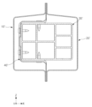
도 1은 본 발명의 차량용 사이드실과 대비되는 비교예 1의 차량용 사이드실의 단면도이다.
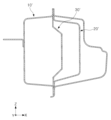
도 2는 본 발명의 차량용 사이드실과 대비되는 비교예 2의 차량용 사이드실의 단면도이다.
도 3은 본 발명의 일실시예에 따른 차량용 사이드실의 사시도이다.
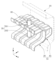
도 4는 본 발명의 일실시예에 따른 차량용 사이드실에서 일부 구성만 나타낸 사시도이다.
도 5는 본 발명의 일실시예에 따른 차량용 사이드실의 보강프레임 및 마운팅프레임을 도 4와 다른 각도에서 바라본 사시도이다.
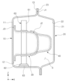
도 6은 본 발명의 일실시예에 따른 차량용 사이드실의 단면도를 도시한다.
도 7a 내지 도 7c는 본 발명의 일실시예에 따른 사이드실이 외부에서 충격을 받는 경우, 충격을 받는 단면 상에서 사이드실의 변형 해석결과를 도시한 도면으로서, 도 7a는 충돌 직전의 상태를 도시하고, 도 7b는 변형되고 있는 충돌 중기의 변형해석 결과이며, 도 7c는 충돌 후기에서의 해석 결과를 도시한다.
도 8a 내지 도 8c는 도 3과 같은 본 발명의 일실시예에 따른 사이드실이 외부에서 충격을 받는 경우 사이드실의 변형 해석 결과를 상부에서 바라본 모습을 도시한 것으로서, 도 8a는 충돌 직전의 상태를 도시하고, 도 8b는 변형되고 있는 충돌 중기의 변형해석 결과이며, 도 8c는 충돌 후기에서의 해석 결과를 도시한다.
도 9는 기존의 실시예에 따른 차량용 사이드실의 단면도이다.
도 10은 본 발명의 일실시예의 차량용 사이드실인 도 3의 차량용 사이드실과 기존의 차량용 사이드실인 도 9의 차량용 사이드실에 대한 하중-변위 선도이다.Figure 1 is a cross-sectional view of a vehicle side sill of Comparative Example 1 in contrast to the vehicle side sill of the present invention.
Figure 2 is a cross-sectional view of a vehicle side sill of Comparative Example 2 in contrast to the vehicle side sill of the present invention.
FIG. 3 is a perspective view of a vehicle side sill according to one embodiment of the present invention.
FIG. 4 is a perspective view showing only a portion of a vehicle side sill according to an embodiment of the present invention.
FIG. 5 is a perspective view of a reinforcing frame and a mounting frame of a vehicle side sill according to an embodiment of the present invention, viewed from a different angle than FIG. 4.
FIG. 6 illustrates a cross-sectional view of a vehicle side sill according to one embodiment of the present invention.
FIGS. 7A to 7C are drawings showing the results of deformation analysis of a side sill on a cross-section that receives an impact when the side sill receives an external impact according to one embodiment of the present invention. FIG. 7A shows the state immediately before a collision, FIG. 7B shows the results of deformation analysis in the middle of a collision while it is being deformed, and FIG. 7C shows the results of analysis in the latter period after a collision.
FIGS. 8A to 8C illustrate the deformation analysis results of the side sill when the side sill according to one embodiment of the present invention, such as FIG. 3, receives an external impact, as viewed from above. FIG. 8A illustrates the state immediately before a collision, FIG. 8B illustrates the deformation analysis results in the middle period of a collision while it is being deformed, and FIG. 8C illustrates the analysis results in the latter period of a collision.
Fig. 9 is a cross-sectional view of a vehicle side sill according to a conventional embodiment.
FIG. 10 is a load-displacement diagram for the vehicle side sill of FIG. 3, which is an embodiment of the vehicle side sill of the present invention, and the vehicle side sill of FIG. 9, which is a conventional vehicle side sill.
이하에서는 첨부된 도면을 참고로 하여, 본 발명의 구체적인 실시예에 대하여 설명하도록 한다. 다만, 본 발명의 사상은 제시되는 실시예에 제한되지 아니하고, 본 발명의 사상을 이해하는 당업자는 동일한 사상의 범위 내에서 다른 구성요소를 추가, 변경 또는 삭제 등을 통하여, 퇴보적인 다른 발명이나 본 발명 사상의 범위 내에 포함되는 다른 실시예를 용이하게 제안할 수 있을 것이나, 이 또한 본원 발명 사상의 범위 내에 포함된다고 할 것이다.Hereinafter, specific embodiments of the present invention will be described with reference to the attached drawings. However, the spirit of the present invention is not limited to the presented embodiments, and those skilled in the art who understand the spirit of the present invention will be able to easily propose other regressive inventions or other embodiments included within the scope of the spirit of the present invention by adding, changing, or deleting other components within the scope of the same spirit, but this will also be considered to be included within the scope of the spirit of the present invention.
도면을 참조하면, 본 발명의 차량용 사이드실은 좌우방향, 상하방향, 전후방향으로 도시하고, 발명의 상세한 설명에도 좌우방향, 상하방향, 전후방향의 용어를 사용하여 설명을 하였으나, 이는 설명의 편의를 위한 것이고, 본 발명의 차량용 사이드실의 기술적 특징이 이러한 방향에 한정되는 것은 아님을 밝혀둔다.Referring to the drawings, the vehicle side sill of the present invention is illustrated in the left-right, up-down, and front-back directions, and although the terms left-right, up-down, and front-back directions are used in the detailed description of the invention, this is for the convenience of explanation, and it is to be noted that the technical features of the vehicle side sill of the present invention are not limited to these directions.
이하, 첨부된 도면에 도시된 X축은 차량용 사이드실의 폭 방향(X 방향)이고, Y축은 차량용 사이드실의 길이방향(Y 방향)이고, Z축은 차량용 사이드실의 높이방향(Z 방향)이다.Below, the X-axis illustrated in the attached drawing is the width direction (X direction) of the vehicle side sill, the Y-axis is the length direction (Y direction) of the vehicle side sill, and the Z-axis is the height direction (Z direction) of the vehicle side sill.
도 1은 본 발명의 차량용 사이드실과 대비되는 비교예 1의 차량용 사이드실의 단면도이다.Figure 1 is a cross-sectional view of a vehicle side sill of Comparative Example 1 in contrast to the vehicle side sill of the present invention.
비교예 1의 경우는, 이너패널(10'), 아우터패널(20'), 보강프레임(30') 및 체결용브라켓(40')을 포함한다. 보강프레임(50, 도 3 참고)에 강재를 사용하는 본 발명의 일 실시예와는 달리, 보강프레임(30')에 알루미늄 압출재를 이용하고 있다. In the case of Comparative Example 1, an inner panel (10'), an outer panel (20'), a reinforcing frame (30'), and a fastening bracket (40') are included. Unlike one embodiment of the present invention in which steel is used for the reinforcing frame (50, see FIG. 3), aluminum extrusion is used for the reinforcing frame (30').
비교예 1이 보강프레임(30')에 알루미늄 압출재를 적용하는 것은 경량화를 위한 방안이나, 충분한 충돌에너지 흡수를 위하여는 두꺼운 단면 구성으로 경량화 효과가 실제 크지 않다는 문제점이 있다.Comparative Example 1 uses aluminum extrusion to reinforce the frame (30') as a way to reduce weight, but has a problem in that the weight reduction effect is not actually significant due to the thick cross-section configuration for sufficient collision energy absorption.
또한, 비교예 1은 높은 원료 가격과 고가의 압출가공공정으로 인해 원가부담이 크다는 문제점이 있고, 이종 소재간 접합을 위해 체결용 브라켓(40') 등을 적용이 필요해지면서 또 다른 무게 증가를 초래하고, 작업성 저하를 초래할 수 있다는 문제점이 있다.In addition, Comparative Example 1 has the problem that the cost burden is high due to the high raw material price and expensive extrusion processing process, and there is the problem that the application of a fastening bracket (40') etc. for joining different materials requires another weight increase and may cause a decrease in workability.
도 2는 본 발명의 차량용 사이드실과 대비되는 비교예 2의 차량용 사이드실의 단면도이다. Figure 2 is a cross-sectional view of a vehicle side sill of Comparative Example 2 in contrast to the vehicle side sill of the present invention.
비교예 2의 경우는, 이너패널(10')과 아우터패널(20')의 사이에 강재를 사용한 보강프레임(30')을 배치하였으나, 비교예 2의 보강프레임(30')은 사이드실의 폭 방향 충돌에너지 흡수하기에는 매우 취약한 구조를 가지고 있다. 이로 인해 승객 및 전기 자동차 배터리 보호를 위하여 사이드실의 실내 유입을 막는데 에는 별 효과를 기대할 수 없었다는 문제점이 있다.In the case of Comparative Example 2, a reinforcing frame (30') using steel was placed between the inner panel (10') and the outer panel (20'), but the reinforcing frame (30') of Comparative Example 2 has a very weak structure in absorbing the width-direction collision energy of the side sill. Due to this, there is a problem in that it is not expected to be very effective in preventing the side sill from entering the interior to protect passengers and the electric vehicle battery.
이하에서는, 본 발명의 일 실시예에 따른 차량용 사이드실에 포함된 구성요소들을 구체적으로 설명하기로 한다.Below, components included in a vehicle side sill according to one embodiment of the present invention will be specifically described.
도 3은 본 발명의 일실시예에 따른 차량용 사이드실을 도시한 단면도이다.FIG. 3 is a cross-sectional view illustrating a vehicle side sill according to one embodiment of the present invention.
본 발명의 일실시예에 따른 차량용 사이드실은, 사이드실프레임과 보강프레임(50) 및 마운팅부재(60)를 포함한다.A vehicle side sill according to one embodiment of the present invention includes a side sill frame, a reinforcing frame (50), and a mounting member (60).
일례로, 사이드실프레임은 이너패널(10)과 아우터패널(20)을 포함하고, 내부에 제1 보강부재(30)와 제2 보강부재(40)를 포함하는 보강프레임(50)이 형성된다. 그리고, 사이드실의 외부에 위치되는 배터리프레임을 결합시키기 위하여 사이드실 프레임과 보강프레임(50)을 관통하여 위치되는 마운팅부재(60)가 구비된다. For example, the side sill frame includes an inner panel (10) and an outer panel (20), and a reinforcing frame (50) including a first reinforcing member (30) and a second reinforcing member (40) is formed inside. In addition, a mounting member (60) positioned to penetrate the side sill frame and the reinforcing frame (50) is provided to connect a battery frame located outside the side sill.
이너패널(10)은 X축 방향으로 사이드실의 폭방향 내측에 배치될 수 있다. 이너패널(10)은 하나의 강판을 성형하여 일체로 제작될 수 있다. 이너패널(10)은 하나의 강판을 성형하여 일체로 제작됨으로써, 단일의 강판으로 구성된 이너패널(10)이 일체로 거동하면서 차량용 사이드실의 기계적 강성이 향상될 수 있다.The inner panel (10) can be arranged on the inner side of the side sill in the width direction in the X-axis direction. The inner panel (10) can be manufactured as a single piece by forming a single steel plate. Since the inner panel (10) is manufactured as a single piece by forming a single steel plate, the mechanical rigidity of the side sill for a vehicle can be improved as the inner panel (10) composed of a single steel plate moves as a single piece.
아우터패널(20)은 X축 방향으로 사이드실의 폭방향 외측에 배치될 수 있다. 아우터패널(20)은 하나의 강판을 성형하여 일체로 제작될 수 있다. 아우터패널(20)은 하나의 강판을 성형하여 일체로 제작됨으로써, 단일의 강판으로 구성된 아우터패널(20)이 일체로 거동하면서 차량용 사이드실의 기계적 강성이 향상될 수 있다.The outer panel (20) can be arranged on the outer side of the side sill in the X-axis direction in the width direction. The outer panel (20) can be manufactured as a single piece by forming a single steel plate. Since the outer panel (20) is manufactured as a single piece by forming a single steel plate, the mechanical rigidity of the vehicle side sill can be improved as the outer panel (20) composed of a single steel plate moves as a single piece.
도 4는 본 발명의 일실시예에 따른 차량용 사이드실에서 일부 구성만 나타낸 사시도를 도시한다.FIG. 4 is a perspective view showing only a portion of a vehicle side sill according to an embodiment of the present invention.
본 발명의 일실시예에 따르면, 마운팅부재(60)는 보강프레임(50)을 관통하여 위치될 수 있다.According to one embodiment of the present invention, the mounting member (60) can be positioned so as to penetrate the reinforcing frame (50).
일례로, 보강프레임(50)은 제1 보강부재(30)와 제2 보강부재(40)를 포함할 수 있다.For example, the reinforcing frame (50) may include a first reinforcing member (30) and a second reinforcing member (40).
보강프레임(50)은 하나의 부재로 이루어질 수 있으나, 외부 충격에 따른 흡수능을 높이기 위하여 복수의 부재로 이루어질 수도 있다.The reinforcing frame (50) may be made of a single member, but may also be made of multiple members to increase the absorption capacity for external impact.
일례로, 제1 보강부재(30)에는 관통홀(35)이 형성될 수 있다.For example, a through hole (35) may be formed in the first reinforcing member (30).
관통홀(35)은 복수개 형성되고, 높이 방향을 따라 상이한 위치에 위치되는 제1 관통홀(351) 및 제2 관통홀(352)을 포함할 수 있다. 그리고 마운팅부재(60)는 제1 보강부재(30)의 관통홀(35)에 끼워지며 제1 보강부재(30)를 관통하여 위치될 수 있다. 이때 관통홀(35)은 길이방향을 따라 복수개 형성될 수 있다.The through holes (35) may be formed in multiple numbers and may include a first through hole (351) and a second through hole (352) positioned at different positions along the height direction. In addition, the mounting member (60) may be fitted into the through hole (35) of the first reinforcing member (30) and positioned by penetrating the first reinforcing member (30). At this time, the through holes (35) may be formed in multiple numbers along the length direction.
이때, 관통홀(35)에 위치된 마운팅부재(60)를 견고하게 고정하기 위하여 관통홀(35)의 둘레를 둘러싸고 용접 접합이 되어 있을 수 있다.At this time, in order to firmly fix the mounting member (60) located in the through hole (35), a welding joint may be formed surrounding the circumference of the through hole (35).
제2 보강부재(40)를 관통하여 마운팅부재(60)가 위치될 수도 있다. 그러나, 제1 보강부재(30)가 이너패널(10) 측에 위치되어 외부 충격에 따라 보강프레임(50)의 변형이 일어날 때 제2 보강부재(40)를 관통하여 마운팅부재(60)가 위치되는 경우보다 안정적인 압괴변형으로 인한 충격흡수가 용이할 수 있다. The mounting member (60) may be positioned by penetrating the second reinforcing member (40). However, when the first reinforcing member (30) is positioned on the inner panel (10) side and deformation of the reinforcing frame (50) occurs due to external impact, shock absorption due to stable crushing deformation can be facilitated more easily than when the mounting member (60) is positioned by penetrating the second reinforcing member (40).
도 5는 본 발명의 일실시예에 따른 차량용 사이드실의 보강프레임 및 마운팅부재를 도 4와 다른 각도에서 바라본 도면이다.FIG. 5 is a drawing of a reinforcing frame and a mounting member of a vehicle side sill according to an embodiment of the present invention, taken from a different angle than FIG. 4.
보강프레임(50)은 상기 중공부(S)에 위치되고 상기 사이드실프레임과 결합되어 폐단면을 형성하고 만곡면을 포함할 수 있다.The reinforcing frame (50) is positioned in the hollow portion (S) and is combined with the side sill frame to form a closed cross-section and may include a curved surface.
보강프레임(50)은 중공부(S)에 위치되어 차량외부에서 충격이 가해지는 경우 중공부(S) 내에서 안정적인 압괴가 발생하여 충돌에너지의 흡수성능이 개선될 수 있다.The reinforcing frame (50) is positioned in the hollow part (S), so that when an impact is applied from outside the vehicle, stable compression occurs within the hollow part (S), thereby improving the absorption performance of collision energy.
일례로, 제1 보강부재(30) 또는 제2 보강부재(40) 중 어느 하나 이상에 상기 길이방향으로 반복되는 요철부(33,43)를 포함할 수 있다.For example, at least one of the first reinforcing member (30) or the second reinforcing member (40) may include a repetitive longitudinally concave portion (33, 43).
보강프레임(50)은 길이방향 단면 상에서 요철부(33, 43)가 반복될 수 있다. 보강프레임(50)은 요철부(33, 43)를 포함함으로써, 보강프레임(50)을 구성하는 강재 등의 두께를 증가시키지 않으면서 강성을 향상시킬 수 있다.The reinforcing frame (50) may have repetitive uneven portions (33, 43) on the longitudinal cross-section. By including the uneven portions (33, 43), the reinforcing frame (50) can improve rigidity without increasing the thickness of the steel material or the like constituting the reinforcing frame (50).
또한, 보강프레임(50)이 요철부(33, 43)를 포함하여 보강프레임(50)의 강성을 충분히 확보함으로써, 차량용 사이드실의 폭방향으로 작용하는 하중에 대해 안정적 압괴가 발생할 수 있고, 충돌에너지 흡수성능을 개선하여 충돌성능을 안정적으로 확보할 수 있는 효과가 있다.In addition, since the reinforcing frame (50) sufficiently secures the rigidity of the reinforcing frame (50) by including the uneven portions (33, 43), stable compression can occur against the load acting in the width direction of the vehicle side sill, and there is an effect of improving the collision energy absorption performance, thereby stably securing the collision performance.
보강프레임(50)은 제1 보강부재(30)와 제2 보강부재(40)를 포함할 수 있다.The reinforcing frame (50) may include a first reinforcing member (30) and a second reinforcing member (40).
제1 보강부재(30)는 상기 아우터패널(20)을 향하여 굴곡진 제1 굴곡부와 상기 이너패널(10)에 접합되는 플랜지(32)를 포함할 수 있다.The first reinforcing member (30) may include a first curved portion curved toward the outer panel (20) and a flange (32) joined to the inner panel (10).
제1 굴곡부는 평평한 면을 포함하고 있을 수 있고, 또는 평평한 면 없이 뾰족하게 굴곡져 있을 수도 있다. 그리고 제1 보강부재(30)의 단부에는 플랜지(32)가 형성되어 이너패널(10)과 면으로 접합될 수 있다.The first bend may include a flat surface, or may be sharply bent without a flat surface. A flange (32) is formed at an end of the first reinforcing member (30) so as to be flush-joined with the inner panel (10).
제2 보강부재(40)는 상기 중공부(S)에 배치되고 상기 제1 보강부재(30)에 결합되며 상기 아우터패널(20)을 향하여 굴곡진 제2 굴곡부(41)를 포함할 수 있다.The second reinforcing member (40) is placed in the hollow portion (S) and is connected to the first reinforcing member (30) and may include a second curved portion (41) that is curved toward the outer panel (20).
제2 보강부재(40)의 양단부에 형성된 다단부(42)가 제1 보강부재(30)의 제1 굴곡부에 끼워지는 등으로 형상 결합될 수 있다.The multi-stage portion (42) formed at both ends of the second reinforcing member (40) can be shaped and joined by being fitted into the first bent portion of the first reinforcing member (30).
다단부(42)에는 굴곡진 부분이 형성되어 제1 보강부재(30)와 결합된 상태로 제1 굴곡부와 가능한 넓은 면적에서 만날 수 있도록 형성될 수 있어 외부 충돌에 따라 안정적으로 변형이 가능할 수 있다.The multi-stage portion (42) can be formed with a curved portion so that it can meet the first curved portion over as wide an area as possible while being combined with the first reinforcing member (30), thereby enabling stable deformation in response to an external collision.
일례로, 제1 굴곡부는 평평하게 형성된 제1 평면부(312)와 제1 평면부(312)로부터 연장된 제1 측면부(311)를 포함할 수 있다. For example, the first bent portion may include a first flat portion (312) formed flatly and a first side portion (311) extending from the first flat portion (312).
일례로, 제1 보강부재(30)는 제1 곡면부(31)를 더 포함할 수 있다. 제1 곡면부(31)는, 제1 굴곡부와 플랜지(32) 사이를 매끄럽게 연결되도록 구비되고, 이를 통하여 해당 부분에 과하게 충격력이 가해지는 것을 방지하고, 외부에 충격력이 가해지면 정상적으로 충격력이 분포되어 압괴변형을 이루도록 형성될 수 있다.For example, the first reinforcing member (30) may further include a first curved portion (31). The first curved portion (31) is provided to smoothly connect between the first bent portion and the flange (32), thereby preventing excessive impact force from being applied to the relevant portion, and may be formed so that when an impact force is applied from the outside, the impact force is normally distributed to cause crushing deformation.
일례로, 제2 굴곡부(41)는 평평하게 형성된 제2 평면부(412)와 제2 평면부(412)와 다단부(42)를 연결하는 제2 측면부(411)를 포함할 수 있다. 또한 제2 보강부재(40)는 제2 굴곡부(41)와 다단부(42) 사이에 형성된 제2 곡면부(44)를 더 포함할 수 있다. 제2 곡면부(44)를 더 포함하여 제2 굴곡부(41)와 다단부(42) 사이를 매끄럽게 연결되도록 하여 해당 부분에 과하게 충격력이 가해지는 것을 방지하여, 충격이 가해진 경우 정상적인 압괴변형에 따라 변형이 발생하도록 형성될 수 있다.For example, the second bent portion (41) may include a second flat portion (412) formed flatly and a second side portion (411) connecting the second flat portion (412) and the multi-stage portion (42). In addition, the second reinforcing member (40) may further include a second curved portion (44) formed between the second bent portion (41) and the multi-stage portion (42). By further including the second curved portion (44), the second bent portion (41) and the multi-stage portion (42) are smoothly connected, thereby preventing excessive impact force from being applied to the relevant portion, and when an impact is applied, deformation may occur according to normal crushing deformation.
제2 측면부(411), 제2 평면부(412)로 둘러싸이도록 형성되어 제1 보강부재(30)와 이루는 폐단면이 형성되고 이를 통하여 측면 충격을 흡수하며 제2 측면부(411)가 변경되기 용이한 형태일 수 있다.It is formed so as to be surrounded by a second side portion (411) and a second flat portion (412), thereby forming a closed cross-section with the first reinforcing member (30), and through this, a side impact is absorbed, and the second side portion (411) can be easily changed.
그리고, 요철부(33,43)는 사이드실프레임의 길이방향으로 돌출면과 내입면이 교번적으로 형성되고, 돌출면(331,431)과 내입면(332, 432)의 사이에 경사면(333, 433)이 형성될 수 있다. In addition, the uneven portions (33, 43) are alternately formed with protruding surfaces and indented surfaces in the longitudinal direction of the side sill frame, and an inclined surface (333, 433) can be formed between the protruding surfaces (331, 431) and the indented surfaces (332, 432).
보강프레임(50)은, 요철부(33, 43)를 가지고, 요철부(33, 43)는 보강프레임(50)의 폭방향 설치폭에 대응되게 폭방향으로 연장 형성될 수 있다.The reinforcing frame (50) has a recessed portion (33, 43), and the recessed portion (33, 43) can be formed to extend in the width direction corresponding to the width of the installation of the reinforcing frame (50).
돌출면(331,431), 내입면(332, 432) 및 경사면(333, 433)은 각각 폭방향으로 연장 형성될 수 있다.The protruding surfaces (331, 431), the indented surfaces (332, 432), and the inclined surfaces (333, 433) can each be formed to extend in the width direction.
보강프레임(50)의 돌출면(331,431), 경사면(333, 433), 내입면(332, 432)이 하중작용 방향인 폭방향으로 연장 형성됨으로써, 사이드실의 폭방향에서 작용하는 하중에 대해 충돌에너지 흡수성능을 안정적으로 확보할 수 있다.Since the protruding surfaces (331, 431), inclined surfaces (333, 433), and inner surfaces (332, 432) of the reinforcing frame (50) are formed to extend in the width direction, which is the direction of load application, the collision energy absorption performance can be stably secured for the load applied in the width direction of the side sill.
돌출면(331,431), 내입면(332, 432) 및 경사면(333, 433)은 길이방향으로 이격하여 배치될 수 있다.The protruding surfaces (331, 431), the indented surfaces (332, 432), and the inclined surfaces (333, 433) can be arranged spaced apart from each other in the longitudinal direction.
요철부(33, 43)는, 보강프레임(50)의 폭방향 설치폭에 대응되게 보강프레임(50)의 폭방향으로 연장 형성될 수 있다. The uneven portion (33, 43) can be formed to extend in the width direction of the reinforcing frame (50) corresponding to the width direction installation width of the reinforcing frame (50).
일례로, 요철부(33, 43)는 이너패널(10)의 제1 내면(12)과 아우터패널(20)의 제2 내면(22) 사이에서 걸쳐서 폭방향으로 연장 형성될 수 있다.For example, the uneven portion (33, 43) can be formed to extend in the width direction between the first inner surface (12) of the inner panel (10) and the second inner surface (22) of the outer panel (20).
일례로, 요철부(33, 43)의 내입면(332, 432)에 관통홀(35)이 형성되고, 이 면에 체결부재가 위치될 수 있다. 내입면(332, 432)에 체결부재가 위치되기 때문에 외부에서 외력을 받아 변형되는 경우에 이너패널(10) 측으로 제1 굴곡부(34)가 찌그러지면서도 제1 보강부재(30)가 파괴되거나 하는 것 없이 에너지를 최대한으로 흡수하면서 변형될 수 있다.For example, a through hole (35) is formed in the inner surface (332, 432) of the uneven portion (33, 43), and a fastening member can be positioned on this surface. Since the fastening member is positioned on the inner surface (332, 432), when an external force is applied and the first bending portion (34) is deformed toward the inner panel (10), the first reinforcing member (30) can be deformed while absorbing energy to the maximum extent without being destroyed.
도 6은 본 발명의 일실시예에 따른 차량용 사이드실의 단면도를 도시한다.FIG. 6 illustrates a cross-sectional view of a vehicle side sill according to one embodiment of the present invention.
이너패널(10)에는 하기 설명될 중공부(S) 측의 면인 제1 내면 (12)과 중공부(S) 측이 아닌 외측면(11)이 형성되고, 이너패널(10) 접합부(13)가 형성될 수 있다. 외측면(11) 측에는 전기차용 배터리 또는 배터리프레임이 구비될 수 있다.The inner panel (10) is formed with a first inner surface (12) which is a surface on the hollow portion (S) side to be described below and an outer surface (11) which is not on the hollow portion (S) side, and a joint (13) of the inner panel (10) can be formed. A battery or battery frame for an electric vehicle can be provided on the outer surface (11).
이러한 전기차용 배터리 또는 배터리프레임이 구비되기 위하여 배터리 프레임과 연결을 위한 구성으로서 마운팅부재(60)가 더 포함될 수 있고, 마운팅부재(60)에 배터리프레임 또는 배터리를 체결부재를 통해 결합 및 고정함으로써 안정적인 압괴 변형을 구현하며, 제작시의 조립이 편리한 효과를 제공한다.In order to provide such an electric vehicle battery or battery frame, a mounting member (60) may be further included as a configuration for connection to the battery frame, and by connecting and fixing the battery frame or battery to the mounting member (60) through a fastening member, stable compression deformation is implemented, and the effect of convenient assembly during manufacturing is provided.
일례로, 체결부재는 볼트일 수 있다. 체결부재가 체결되는 경우, 마운팅부재(60)의 강성 유지와 소음 진동이 개선될 수 있다. 일례로, 체결부재가 안정적으로 체결될 수 있도록 마운팅부재(60)는 샤프트너트 일 수 있다. 또한, 마운팅부재(60)는 체결부재와 결합될 수 있도록 내부에 볼트의 나사선과 결합되는 형상을 구비할 수 있다. 그러나 체결부재와 마운팅부재는 함께 결합되는 부재일 뿐 상기의 예시에 한정되지 않는다.For example, the fastening member may be a bolt. When the fastening member is fastened, the rigidity of the mounting member (60) can be maintained and noise and vibration can be improved. For example, the mounting member (60) may be a shaft nut so that the fastening member can be stably fastened. In addition, the mounting member (60) may have a shape that is combined with the threads of the bolt inside so that it can be combined with the fastening member. However, the fastening member and the mounting member are merely members that are combined together and are not limited to the above examples.
또한, 마운팅부재(60)를 이너패널(10)과 보강프레임(50)에 브라켓과 같은 추가적인 구성 없이 접합 및 결합하여 경량화, 원가절감, 체결력 및 측면충돌에 따른 흡수능 향상을 제공한다.In addition, the mounting member (60) is joined and combined with the inner panel (10) and the reinforcing frame (50) without additional components such as brackets, thereby providing weight reduction, cost reduction, fastening strength, and improved absorption capacity due to side collisions.
아우터패널(20)은 이너패널(10)과 폭방향으로 결합되어 이너패널(10)과 함께 중공부(S)를 형성할 수 있다. 그리고, 중공부(S)에 보강프레임(50)이 배치될 수 있다.The outer panel (20) can be joined to the inner panel (10) in the width direction to form a hollow portion (S) together with the inner panel (10). In addition, a reinforcing frame (50) can be placed in the hollow portion (S).
이너패널(10), 아우터패널(20), 보강프레임(50), 마운팅부재(60) 등의 구성요소 간의 접합은 용접 접합 또는 접착제 접합 등의 다양한 접합방식이 적용될 수 있다.The connection between components such as the inner panel (10), outer panel (20), reinforcing frame (50), and mounting member (60) can be applied using various connection methods such as welding or adhesive connection.
이너패널(10)과 아우터패널(20)의 접합 부분인 제1 접합 부분(J1)은 점용접, 아크용접 또는 구조용접착제로 결합된 부분일 수 있다.The first joint portion (J1), which is the joint portion between the inner panel (10) and the outer panel (20), may be a portion joined by spot welding, arc welding, or structural adhesive.
보강프레임(50)의 제1 보강부재(30)와 제2 보강부재(40)의 접합 부분인 제2 접합 부분(J2)은 구조용 접착제 또는 레이저 용접 또는 플러그 용접으로 결합된 부분일 수 있다.The second joint portion (J2), which is the joint portion between the first reinforcing member (30) and the second reinforcing member (40) of the reinforcing frame (50), may be a portion joined by structural adhesive, laser welding, or plug welding.
보강프레임(50)과 이너패널(10)의 접합 부분인 제3 접합 부분(J3)은 레이저 용접 또는 아크 용접으로 결합된 부분일 수 있다. The third joint portion (J3), which is the joint portion between the reinforcing frame (50) and the inner panel (10), may be a portion joined by laser welding or arc welding.
일례로, 마운팅부재(60)와 이너패널(10)은 접합되면서 접합 부분이 용접부(63)로 형성될 수 있다. 이너패널(10)과 마운팅부재(60)는 상기 언급한 것과 같이 접합으로 용접부(63)가 형성될 수 있고, 이는 아크 용접에 의한 용접부(63)일 수 있다. 마운팅부재(60)가 이너패널(10)과 맞닿아 직접 용접으로 접합되어 견고하게 결합될 수 있다.For example, the mounting member (60) and the inner panel (10) may be joined to form a joint portion as a weld (63). The inner panel (10) and the mounting member (60) may be joined to form a weld (63) as mentioned above, and this may be a weld (63) by arc welding. The mounting member (60) may be firmly joined by directly welding the inner panel (10) in contact with it.
일례로, 마운팅부재(60)는 내부가 비어 있는 원기둥 형상으로 높이방향으로 연장된 기둥부(61)와, 기둥부(61)의 일단에 형성된 확장부(62)와, 확장부(62)를 둘러싸고 이너패널(10)과 접합된 용접부(63)가 형성될 수 있다. For example, the mounting member (60) may be formed with a columnar shape with an interior that is hollow and extends in the height direction, an extension (62) formed at one end of the column (61), and a weld (63) that surrounds the extension (62) and is joined to the inner panel (10).
기둥부(61)는 중공의 길이방향 확장부(62)가 형성되어 체결부재의 결합시 각도가 조금 벗어나도 인입시켜 정렬하여 체결하기 용이하게 형성될 수 있다. The pillar part (61) is formed with a hollow longitudinal extension part (62) so that even if the angle is slightly off when joining the fastening members, they can be easily aligned and fastened.
일례로, 이너패널(10), 아우터패널(20), 보강프레임(50) 중 적어도 어느 하나는 강재로 구성될 수 있다. 또는, 이너패널(10), 아우터패널(20) 및 보강프레임(50)은 강재로 구성될 수 있다. 이에 따라, 차량용 사이드실의 기계적 강성이 향상될 수 있다.For example, at least one of the inner panel (10), the outer panel (20), and the reinforcing frame (50) may be made of steel. Alternatively, the inner panel (10), the outer panel (20), and the reinforcing frame (50) may be made of steel. Accordingly, the mechanical rigidity of the vehicle side sill may be improved.
본 발명의 일실시예에 따르면, 아우터패널(20)과 제2 보강부재(40)는 이격 배치될 수 있다. 제2 보강부재(40)는 조립의 편의성을 위하여 아우터패널(20)과 이격 배치될 수 있다. According to one embodiment of the present invention, the outer panel (20) and the second reinforcing member (40) may be spaced apart from each other. The second reinforcing member (40) may be spaced apart from the outer panel (20) for convenience of assembly.
그러나, 제2 보강부재(40)가 아우터패널(20)과 접합되어 있을 수 있고, 이 경우 접합 부분은 구조용접착제 또는 단면 레이저 용접, 또는 플러그 용접 등으로 접합되어 있을 수 있다. However, the second reinforcing member (40) may be joined to the outer panel (20), in which case the joining portion may be joined using a structural adhesive, cross-sectional laser welding, or plug welding.
본 발명의 일실시예에 따르면, 제1 보강부재(30) 또는 제2 보강부재(40)는, 980MPa 이상의 인장강도를 가지는 하나의 강판을 성형하여 제작될 수 있다. According to one embodiment of the present invention, the first reinforcing member (30) or the second reinforcing member (40) can be manufactured by forming a single steel plate having a tensile strength of 980 MPa or more.
제1 보강부재(30) 또는 제2 보강부재(40)의 제작에 980MPa 이상의 인장강도를 가지는 고강도 강재를 활용하고, 제1 보강부재(30) 또는 제2 보강부재(40)가 하나의 강판으로 구성되어 제1 보강부재(30) 또는 제2 보강부재(40)가 일체로 거동하면서 기계적 강성이 향상될 수 있다.When manufacturing the first reinforcing member (30) or the second reinforcing member (40), high-strength steel having a tensile strength of 980 MPa or more is used, and since the first reinforcing member (30) or the second reinforcing member (40) is formed of a single steel plate, the mechanical rigidity can be improved as the first reinforcing member (30) or the second reinforcing member (40) moves as a single piece.
또한, 본 발명의 차량용 사이드실은 폼포밍 또는 크래쉬 포밍 등의 저원가 성형공법을 이용하여 980MPa 이상의 인장강도를 가지는 강판을 활용하여 제1 보강부재(30) 또는 제2 보강부재(40)를 제작할 수 있다.In addition, the vehicle side sill of the present invention can be manufactured by using a steel plate having a tensile strength of 980 MPa or more using a low-cost forming method such as foam forming or crash forming to manufacture the first reinforcing member (30) or the second reinforcing member (40).
도 7a 내지 도 7c는 본 발명의 일실시예에 따른 사이드실이 외부에서 충격을 받는 경우, 충격을 받는 단면 상에서 사이드실의 변형 해석결과를 도시한 내용으로서 시간에 따라 도 7a부터 7c로 진행한다. 도 7a는 충돌 직전의 상태를 도시하고, 도 7b는 변형되고 있는 충돌 중기의 변형해석 결과이며, 도 7c는 충돌 후기에서의 해석 결과를 도시한다.FIGS. 7A to 7C illustrate the deformation analysis results of the side sill on the cross-section receiving the impact when the side sill according to one embodiment of the present invention receives an external impact, and progress from FIGS. 7A to 7C over time. FIG. 7A illustrates the state immediately before the impact, FIG. 7B illustrates the deformation analysis results in the middle of the impact while it is being deformed, and FIG. 7C illustrates the analysis results in the latter period of the impact.
도 7a 내지 도 7c에서 볼 수 있듯이, 차량의 폭방향으로 보강프레임(50)이 압괴되며 변형이 일어나고, 제1 보강부재(30) 및 제2 보강부재(40)가 순차적으로 에너지를 흡수하는 것을 알 수 있다. 따라서, 안정적인 충돌변형이 발생되는 것을 확인할 수 있다.As can be seen in FIGS. 7a to 7c, the reinforcing frame (50) is compressed and deformed in the width direction of the vehicle, and the first reinforcing member (30) and the second reinforcing member (40) sequentially absorb energy. Accordingly, it can be confirmed that stable collision deformation occurs.
도 8a 내지 도 8c는 도 3과 같은 본 발명의 일실시예에 따른 사이드실이 외부에서 충격을 받는 경우 사이드실의 변형 해석 결과를 상부에서 바라본 모습을 도시한 것으로서, 시간에 따라 도 8a부터 8c로 진행한다. 도 8a는 충돌 직전의 상태를 도시하고, 도 8b는 변형되고 있는 충돌 중기의 변형해석 결과이며, 도 8c는 충돌 후기에서의 해석 결과를 도시한다.FIGS. 8A to 8C illustrate deformation analysis results of a side sill when the side sill according to one embodiment of the present invention, such as FIG. 3, receives an external impact, as viewed from above, progressing from FIGS. 8A to 8C over time. FIG. 8A illustrates a state immediately before a collision, FIG. 8B illustrates a deformation analysis result in the middle of a collision while it is being deformed, and FIG. 8C illustrates an analysis result in the latter period of a collision.
도 8a 내지 도 8c에서 볼 수 있듯이, 차량의 폭방향으로 보강프레임(50)이 압괴되며 변형이 일어나고, 보강프레임(50)이 외부 충격을 흡수하고 마운팅부재(60)는 거의 변형 없이 효율적으로 에너지가 적게 되는 것을 알 수 있다. 따라서, 전기차의 경우 내부에 존재하는 배터리에 영향을 덜 미치게 되고, 탑승객을 보호할 수 있는 것을 알 수 있다.As can be seen in FIGS. 8A to 8C, the reinforcing frame (50) is compressed and deformed in the width direction of the vehicle, and it can be seen that the reinforcing frame (50) absorbs external impact and the mounting member (60) efficiently reduces energy with almost no deformation. Accordingly, it can be seen that in the case of an electric vehicle, the battery inside is less affected and passengers can be protected.
도 9는 기존의 실시예에 따른 차량용 사이드실로서, 마운팅브라켓을 더 구비하여, 마운팅부재(600)가 브라켓에 결합되고 이너패널(100)에 직접적으로 결합되지 않은 상태를 도시한다.FIG. 9 illustrates a side sill for a vehicle according to a conventional embodiment, further comprising a mounting bracket, with a mounting member (600) coupled to the bracket and not directly coupled to the inner panel (100).
기존의 실시예에 따른 차량용 사이드실은, 이너패널(100)과 아우터패널(200)이 결합되고, 내부에 보강프레임(400)을 구비할 수 있다. 다만, 마운팅브라켓(700)을 더 구비하여 마운팅부재(600)는 마운팅브라켓(700)에 의하여 고정 결합될 수 있다. 본발명의 일실시예와 비교하면, 마운팅부재(600)는 마운팅브라켓(700)에만 결합되고, 이너패널(100)은 관통할 뿐 본 발명과 같이 용접 등의 수단으로 직접적으로 접합되지 않는다는 데 차이가 있다.According to the existing embodiment, the vehicle side sill may be provided with an inner panel (100) and an outer panel (200) coupled together and a reinforcing frame (400) provided inside. However, a mounting bracket (700) may be further provided so that the mounting member (600) may be fixedly coupled by the mounting bracket (700). Compared to an embodiment of the present invention, there is a difference in that the mounting member (600) is coupled only to the mounting bracket (700), and the inner panel (100) is not directly joined by means such as welding as in the present invention, but rather penetrates.
도 10은 본 발명의 일실시예의 차량용 사이드실인 도 3의 차량용 사이드실과 기존의 차량용 사이드실인 도 9의 차량용 사이드실에 대한 하중-변위 선도이다. 구체적으로, 충돌 단위무게당 충돌에너지 흡수능을 비교 분석한 그래프로서, 제1 값(L1)의 내부의 면적은 본 발명의 일실시예에 따른 차량용 사이드실의 내부에너지에 해당하고, 제2 값(L2)의 내부의 면적은 기존의 일실시예의 차량용 사이드실의 내부에너지에 해당할 수 있다.FIG. 10 is a load-displacement diagram of the vehicle side sill of FIG. 3, which is an embodiment of the present invention, and the vehicle side sill of FIG. 9, which is a conventional vehicle side sill. Specifically, as a graph comparing and analyzing collision energy absorption capacity per collision unit weight, the area inside a first value (L1) may correspond to the internal energy of the vehicle side sill according to the embodiment of the present invention, and the area inside a second value (L2) may correspond to the internal energy of the vehicle side sill of the conventional embodiment.
구체적으로, 기존의 차량용 사이드실의 내부에너지(ineternal energy)는 51.3 KJ이고, 기존의 차량용 사이드실의 중량은 26.5 kg이었고, 본 발명의 일실시예의 차량용 사이드실의 내부에너지는 52.3 KJ이고, 본 발명의 일실시예의 차량용 사이드실의 중량은 24.2 kg이었다.Specifically, the internal energy of the existing vehicle side sill was 51.3 KJ, the weight of the existing vehicle side sill was 26.5 kg, and the internal energy of the vehicle side sill of one embodiment of the present invention was 52.3 KJ, and the weight of the vehicle side sill of one embodiment of the present invention was 24.2 kg.
즉, 기존의 차량용 사이드실의 단위기준 내부에너지(1kg당 ineternal energy 비율)는 1.94 KJ/kg이고, 본 발명의 실시예에 따른 차량용 사이드실의 단위기준 내부에너지는 2.16 KJ/kg인바, 본 발명의 일실시예에 따른 차량용 사이드실이 기존의 차량용 사이드실에 비해 에너지 흡수성능이 보다 우수하고, 1kg 당 내부에너지의 비율이 커서 단위 무게당 에너지 흡수성능이 보다 우수한 것을 알 수 있다.That is, the unit-based internal energy (the internal energy ratio per 1 kg) of the existing vehicle side sill is 1.94 KJ/kg, and the unit-based internal energy of the vehicle side sill according to the embodiment of the present invention is 2.16 KJ/kg. Therefore, it can be seen that the vehicle side sill according to the embodiment of the present invention has better energy absorption performance than the existing vehicle side sill, and has a greater ratio of internal energy per 1 kg, so that the energy absorption performance per unit weight is better.
따라서, 본 발명의 일실시예에 따른 차량용 사이드실은 기존의 차량용 사이드실에 비해 중량이 가벼우면서 충돌에너지 흡수성능이 우수하여 충돌성능을 안정적으로 확보할 수 있는 효과가 있다.Accordingly, the vehicle side sill according to one embodiment of the present invention is lighter than the existing vehicle side sill and has excellent collision energy absorption performance, thereby having the effect of stably securing collision performance.
이상에서는 본 발명을 실시예를 중심으로 설명하였지만, 본 발명은 상술한 실시예에 한정되지 않으며, 청구범위에서 청구되는 본 발명의 기술적 사상의 변화 없이 통상의 기술자에 의해서 변형되어 실시될 수 있음은 물론이다.Although the present invention has been described above with reference to examples, the present invention is not limited to the above-described examples, and it goes without saying that modifications may be made and implemented by those skilled in the art without changing the technical idea of the present invention as claimed in the claims.
10: 이너패널
20: 아우터패널
30: 제1 보강부재
31: 제1 곡면부
32: 플랜지
33,43: 요철부
34: 제1 곡면부
35: 관통홀
40: 제2 보강부재
41: 제2 굴곡부
42: 다단부
44: 제2 곡면부
50: 보강프레임
60: 마운팅부재
61: 기둥부
62: 확장부
63: 용접부
J1, J2, J3: 접합 부분
S: 중공부
10: Inner panel 20: Outer panel
30: First reinforcing member 31: First curved portion
32:
34: First curved surface 35: Through hole
40: Second reinforcing member 41: Second bending member
42: Multi-stage section 44: Second curved section
50: Reinforcement frame 60: Mounting member
61: Column 62: Extension
63: Welding J1, J2, J3: Joint
S: The Central Department
Claims (13)
상기 중공부에 위치되고 상기 사이드실프레임과 결합되어 폐단면을 형성하고 만곡면을 포함하는 보강프레임; 및
상기 차량의 높이방향으로 상기 보강프레임을 관통하고, 상기 사이드실프레임과 접합되며 내부에 체결부재가 결합되는 마운팅부재;를 포함하는 차량용 사이드실.
A side sill frame having a hollow space formed inside and extending in the longitudinal direction of the vehicle;
A reinforcing frame positioned in the above hollow portion and combined with the side sill frame to form a closed cross-section and including a curved surface; and
A vehicle side sill, comprising: a mounting member penetrating the reinforcing frame in the height direction of the vehicle, joined to the side sill frame, and having a fastening member joined therein;
상기 마운팅부재는, 상기 사이드실프레임과 용접 접합되는 차량용 사이드실.
In the first paragraph,
The above mounting member is a vehicle side sill that is welded to the side sill frame.
상기 사이드실프레임은, 이너패널과 아우터패널을 포함하고, 상기 이너패널은 상기 아우터패널보다 차량의 폭방향으로 내측에 위치되며,
상기 마운팅부재는, 상기 이너패널에 접합되는 차량용 사이드실.
In the second paragraph,
The above side sill frame includes an inner panel and an outer panel, and the inner panel is positioned further inward in the width direction of the vehicle than the outer panel.
The above mounting member is a vehicle side sill that is attached to the inner panel.
상기 보강프레임은,
상기 아우터패널을 향하여 굴곡진 제1 굴곡부와 상기 마운팅부재가 위치되는 관통홀과 상기 이너패널에 접합되는 플랜지를 포함하는 제1 보강부재와,
상기 중공부에 배치되고, 상기 제1 보강부재에 결합되며, 상기 아우터패널을 향하여 굴곡진 제2 굴곡부를 포함하는 제2 보강부재를 포함하고,
상기 마운팅부재는 상기 제1 보강부재를 관통하여 위치되는 차량용 사이드실.
In the third paragraph,
The above reinforcing frame is,
A first reinforcing member including a first curved portion that is curved toward the outer panel, a through hole in which the mounting member is positioned, and a flange that is joined to the inner panel,
A second reinforcing member is disposed in the above hollow portion, is coupled to the first reinforcing member, and includes a second curved portion that is curved toward the outer panel.
A vehicle side sill in which the above-mentioned mounting member is positioned so as to penetrate the above-mentioned first reinforcing member.
상기 제1 보강부재 또는 상기 제2 보강부재 중 어느 하나 이상에 상기 길이방향으로 반복되는 요철부를 포함하는 차량용 사이드실.
In paragraph 4,
A vehicle side sill including a recessed portion repeating in the longitudinal direction on at least one of the first reinforcing member and the second reinforcing member.
상기 요철부는, 상기 사이드실프레임의 길이방향으로 돌출면과 내입면이 교번적으로 형성되고, 상기 돌출면과 상기 내입면의 사이에 경사면이 형성되는 차량용 사이드실.
In paragraph 5,
A vehicle side sill in which the above-mentioned recessed portion has protruding surfaces and indented surfaces alternately formed in the longitudinal direction of the side sill frame, and an inclined surface is formed between the protruding surfaces and the indented surfaces.
상기 마운팅부재는, 상기 이너패널의 일면과 이격되는 차량용 사이드실.
In paragraph 4,
The above mounting member is a vehicle side sill spaced apart from one side of the inner panel.
상기 아우터패널과 상기 제2 보강부재는 이격 배치되는 차량용 사이드실.
In paragraph 4,
A vehicle side sill in which the above outer panel and the second reinforcing member are spaced apart from each other.
상기 제1 보강부재 또는 상기 제2 보강부재 중 어느 하나 이상의 강판은,
폼포밍 또는 크래쉬포밍 방식에 의해 성형되는 차량용 사이드실.
In paragraph 4,
At least one of the first reinforcing member or the second reinforcing member is a steel plate,
A side sill for a vehicle formed by foam forming or crash forming.
상기 제1 보강부재 또는 상기 제2 보강부재는,
980MPa이상의 인장강도를 가지는 하나의 강판을 성형하여 제작되는 차량용 사이드 실.
In paragraph 4,
The above first reinforcing member or the above second reinforcing member,
A vehicle side sill manufactured by forming a single steel plate with a tensile strength of 980 MPa or more.
상기 요철부는,
상기 보강프레임의 폭방향 설치폭 전체에 걸쳐서 폭방향으로 연장 형성되는 차량용 사이드실.
In Article 6,
The above-mentioned uneven portion is,
A vehicle side sill formed to extend in the width direction over the entire width of the above-mentioned reinforcing frame.
상기 마운팅부재와 상기 이너패널은 접합되면서 용접부가 형성되는 차량용 사이드실.
In the third paragraph,
A vehicle side sill in which the above mounting member and the inner panel are joined to form a welded portion.
상기 마운팅부재는 상기 내입면을 관통하여 위치되는 차량용 사이드실.
In Article 6,
A vehicle side sill in which the above mounting member is positioned so as to penetrate the inner surface.
Priority Applications (1)
| Application Number | Priority Date | Filing Date | Title |
|---|---|---|---|
| KR1020230182565A KR20250092425A (en) | 2023-12-15 | 2023-12-15 | Side sill of vehicle |
Applications Claiming Priority (1)
| Application Number | Priority Date | Filing Date | Title |
|---|---|---|---|
| KR1020230182565A KR20250092425A (en) | 2023-12-15 | 2023-12-15 | Side sill of vehicle |
Publications (1)
| Publication Number | Publication Date |
|---|---|
| KR20250092425A true KR20250092425A (en) | 2025-06-24 |
Family
ID=96221613
Family Applications (1)
| Application Number | Title | Priority Date | Filing Date |
|---|---|---|---|
| KR1020230182565A Pending KR20250092425A (en) | 2023-12-15 | 2023-12-15 | Side sill of vehicle |
Country Status (1)
| Country | Link |
|---|---|
| KR (1) | KR20250092425A (en) |
Citations (1)
| Publication number | Priority date | Publication date | Assignee | Title |
|---|---|---|---|---|
| KR19980043143U (en) | 1996-12-24 | 1998-09-25 | 양재신 | Reinforcement structure of side seal for automobile |
-
2023
- 2023-12-15 KR KR1020230182565A patent/KR20250092425A/en active Pending
Patent Citations (1)
| Publication number | Priority date | Publication date | Assignee | Title |
|---|---|---|---|---|
| KR19980043143U (en) | 1996-12-24 | 1998-09-25 | 양재신 | Reinforcement structure of side seal for automobile |
Similar Documents
| Publication | Publication Date | Title |
|---|---|---|
| KR102575806B1 (en) | Side sill parts for automobiles | |
| KR101097018B1 (en) | Automotive doors with enhanced side impact performance | |
| JP6142978B1 (en) | Vehicle front structure | |
| CN108430857B (en) | Vehicle rear structure | |
| JP7288183B2 (en) | body parts | |
| WO2020149170A1 (en) | Vehicle body structure | |
| JP7099552B2 (en) | Structural members and body structure | |
| CN104144839B (en) | Impact energy absorbing column and railway vehicle equipped with the impact energy absorbing column | |
| JP2004148994A (en) | Shock absorber for vehicles | |
| CN111629921A (en) | Shock Absorber | |
| JPH06101732A (en) | Shock absorbing member for composite structure | |
| JP7456836B2 (en) | vehicle | |
| EP3386847B1 (en) | Vehicle underbody structure comprising a reinforcement element between a longitudinal beam and a lowerside sill part | |
| KR101374737B1 (en) | Door impact absorption member for vehicle | |
| KR20250092425A (en) | Side sill of vehicle | |
| KR100978216B1 (en) | Bumper Beam Unit for Vehicle | |
| CN113613985B (en) | Composite elongate member | |
| KR20250092406A (en) | Side sill for vehicle | |
| JPH11348818A (en) | Automotive shock absorbing member and structure | |
| JP2010105537A (en) | Vehicle front body structure | |
| KR102202098B1 (en) | Seat cross member assembly for vehicles | |
| KR20250093854A (en) | Side sill for vehicle | |
| KR20250012254A (en) | Side sill for vehicle | |
| KR20240098432A (en) | Bumper beam for vehicle | |
| JP2025123169A (en) | Side sill reinforcement structure |
Legal Events
| Date | Code | Title | Description |
|---|---|---|---|
| PA0109 | Patent application |
Patent event code: PA01091R01D Comment text: Patent Application Patent event date: 20231215 |
|
| PG1501 | Laying open of application |