KR910000004B1 - Bead punching method of equipment - Google Patents
Bead punching method of equipment Download PDFInfo
- Publication number
- KR910000004B1 KR910000004B1 KR1019880010945A KR880010945A KR910000004B1 KR 910000004 B1 KR910000004 B1 KR 910000004B1 KR 1019880010945 A KR1019880010945 A KR 1019880010945A KR 880010945 A KR880010945 A KR 880010945A KR 910000004 B1 KR910000004 B1 KR 910000004B1
- Authority
- KR
- South Korea
- Prior art keywords
- bead
- drill
- drilling
- shaft
- cam
- Prior art date
- Legal status (The legal status is an assumption and is not a legal conclusion. Google has not performed a legal analysis and makes no representation as to the accuracy of the status listed.)
- Expired
Links
- 239000011324 bead Substances 0.000 title claims description 99
- 238000000034 method Methods 0.000 title claims description 26
- 238000004080 punching Methods 0.000 title description 5
- 238000005553 drilling Methods 0.000 claims description 33
- 239000000463 material Substances 0.000 claims description 14
- 238000003756 stirring Methods 0.000 claims description 14
- 230000005540 biological transmission Effects 0.000 claims description 4
- 230000003028 elevating effect Effects 0.000 claims description 4
- 238000012546 transfer Methods 0.000 claims description 3
- 238000005452 bending Methods 0.000 description 7
- 230000002950 deficient Effects 0.000 description 4
- 238000000465 moulding Methods 0.000 description 4
- 230000000149 penetrating effect Effects 0.000 description 3
- 230000004888 barrier function Effects 0.000 description 2
- 238000007373 indentation Methods 0.000 description 2
- 238000004891 communication Methods 0.000 description 1
- 230000000694 effects Effects 0.000 description 1
- 239000004744 fabric Substances 0.000 description 1
- 238000003780 insertion Methods 0.000 description 1
- 230000037431 insertion Effects 0.000 description 1
- 238000012544 monitoring process Methods 0.000 description 1
- 230000002093 peripheral effect Effects 0.000 description 1
- 238000012545 processing Methods 0.000 description 1
Images





Classifications
-
- B—PERFORMING OPERATIONS; TRANSPORTING
- B26—HAND CUTTING TOOLS; CUTTING; SEVERING
- B26F—PERFORATING; PUNCHING; CUTTING-OUT; STAMPING-OUT; SEVERING BY MEANS OTHER THAN CUTTING
- B26F1/00—Perforating; Punching; Cutting-out; Stamping-out; Apparatus therefor
- B26F1/16—Perforating by tool or tools of the drill type
Landscapes
- Life Sciences & Earth Sciences (AREA)
- Forests & Forestry (AREA)
- Engineering & Computer Science (AREA)
- Mechanical Engineering (AREA)
- Drilling And Boring (AREA)
Abstract
내용 없음.No content.
Description
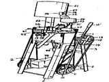
제1도는 본 발명의 전체 외관사시도.1 is a perspective view of the overall appearance of the present invention.
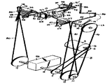
제2도는 제1도의 작동부분 발췌사시도.FIG. 2 is an excerpt perspective view of the working part of FIG. 1. FIG.
제3도는 제1도의 정면도.3 is a front view of FIG.
제4도는 제1도의 평면도.4 is a plan view of FIG.
제5도는 본 발명의 교반장치 발췌사시도.Figure 5 is an excerpt perspective view of the stirring device of the present invention.
제6도는 본 발명의 비이드 공급장치 발췌사시도.Figure 6 is an excerpt perspective view of the bead supply device of the present invention.
제7도는 제6도의 단면도.7 is a cross-sectional view of FIG.
제8도는 본 발명의 비이드 고정장치 발췌사시도.8 is a perspective view of the bead fixing device of the present invention.
제9도는 제8도의 가동테이블 발췌사시도.9 is an exploded perspective view of the movable table of FIG.
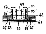
제10도는 제9도의 평단면도.10 is a cross-sectional view of FIG.
제11도는 본 발명의 비이드 천공장치 발췌사시도.11 is a perspective view of the bead puncture device of the present invention.
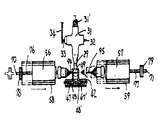
제12a,b,c도는 제11도의 작동상태 평면도.12a, b, and c are plan views of the operating state of FIG.
제13도는 본 발명에 의해서 관통공이 천공된 비이드.Figure 13 is a bead through-hole perforated by the present invention.
* 도면의 주요부분에 대한 부호의 설명* Explanation of symbols for main parts of the drawings
1 : 베드 2 : 각주1: bed 2: footnote
3 : 모터 5 : 하부축3: motor 5: lower shaft
12 : 상부축 15 : 핸들12: upper shaft 15: handle
16 : 클터치 19 : 제1캠축16: touch 19: first camshaft
20 : 제2캠축 21 : 저장통20: second camshaft 21: reservoir
24 : 공급통 29 : 안내로24: supply container 29: guide
30 : 걸림턱 31 : 십자헤드30: Jam Jaw 31: Cross Head
31' : 스프링 34 : 연결간31 ': Spring 34: Between connections
39,54,64,65 : 캠 43 : 승강판39,54,64,65: Cam 43: Platform
44,45 : 가동테이블 50,52 : 수직연결간44,45: movable table 50,52: between vertical connection
51 : 수평연결간 56,57 : 드릴머신51: Between
58,59 : 슬라이더 60,61 : 안내홈58,59: Slider 60,61: Guide groove
62,63 : 안내레일 66,67 : 접동간62,63: guide rail 66,67: sliding
76,77 : 드릴축 82 : 배출홈76,77: drill shaft 82: discharge groove
83 : 배출관 84 : 회동간83
85 : 연결간 86 : 수직회동간85: Between Connections 86: Between Vertical Rotations
87 : 수평회동간 88 : 교반체87: horizontal rotation 88: agitator
89 : 축지지부 90 : 회전지지축89: shaft support portion 90: rotation support shaft
91 : 스탠드 92,93 : 리미트스위치91: stand 92,93: limit switch
94,95 : 드릴 96,97 : 와이어94,95: Drill 96,97: Wire
98 : 브레이크98: brake
본 발명은 성형프레스등에 의해서 구형으로 완성된 비이드의 자동으로 관통공을 비이드의 천공방법 및 그 장치에 관한 것이다.The present invention relates to a method and a device for drilling a bead through a hole automatically completed in a sphere by a molding press or the like.
성형프레스등으로 완성한 구형의 비이드를 목걸이, 팔찌등의 장신구로 만들기 위해서는 중심에 연결줄을 꿰기 위한 관통공을 천공하여야 하는데, 종래에는 비이드 하나 하나를 드릴로 천공하였던 것을 이는 수동작업에 의한 것이어서 비이드의 중심을 정확하게 관통시키지 못하고 편심공을 천공하는 경우가 빈번하여 불량품의 발생이 속출하였고, 이 불량품으로 완제품을 제작했을시에 완제품이 저급품이 되는 것은 너무도 당연하다.To make spherical beads finished by molding press into jewelry such as necklaces and bracelets, it is necessary to drill through-holes for connecting connecting lines in the center. In the past, the beads were drilled one by one because of manual work. Since the eccentric hole was frequently drilled without accurately penetrating the center of the bead, the generation of defective products continued. As a result, when the finished product was manufactured from the defective products, the finished product became too low quality.
또한, 수동에 의한 작업으로 천공시간이 오래 걸리고 많은 인원을 필요로 하여 인건비가 대폭 증가되어 생산단가가 높아져서 생산성이 현저히 저하되는 문제점이 있었다.In addition, the manual work takes a long time for drilling and requires a large number of personnel, which leads to a significant increase in labor costs, resulting in a significant decrease in productivity.
본 발명자는 이와 같은 문제점을 해결하기 위하여 본 발명을 발명한 것으로, 비이드의 천공방법을 전자동화 하여 천공시간 및 작업인원을 대폭적으로 감소시켜서 생산성을 크게 향상시키고, 비이드의 중심을 정확하게 관통시켜서 천공할 수 있도록 된 비이드의 천공방법 및 그 장치를 제공하는데 본 발명의 목적이 있는 것이다.The present inventors have invented the present invention in order to solve the above problems, by fully automating the drilling method of the bead to drastically reduce the drilling time and the number of working people to greatly improve the productivity, to accurately penetrate the center of the bead It is an object of the present invention to provide a method and a device for drilling a bead that can be punched.
즉, 본 발명은 상기와 같은 목적을 달성하기 위한 방법으로 성형프레스등에 의해서 구형으로 성형된 비이드를 하나씩 가동테이블에 공급하기 위한 공급공정과, 이 공급공정에서 공급되는 비이드를 협지하기 위한 고정공정과, 이 고정공정에서 고정된 비이드에 관통공을 천공하는 천공공정으로 구성된 비이드의 천공방법인 것이다.That is, the present invention is a method for achieving the above object, the supply step for supplying the beads formed in a spherical shape by a molding press or the like to the movable table one by one, and the fixing for holding the beads supplied in this supply step It is a method of punching a bead comprising a step of punching a through hole in a bead fixed in this fixing step.
또한, 상기 공급공정에서는 비이드의 공급이 원활하게 이루어지도록 저장된 비이드를 교반시키는 것이 바람직스럽다.In addition, in the supplying step, it is preferable to stir the stored beads so that the supply of the beads is smooth.
본 발명의 상기와 같은 천공방법을 수행하는 장치로서는, 모터에 의해 구동되는 상부축과 하부축, 및 드릴축 그리고 상부축의 회전을 직교로 변환시킨 제1, 제2캠축으로 된 전동장치와, 구형으로 완성된 비이드를 저장하는 저장통 및 공급통과 제1캠축 후단에 축설한 캠에 연결간으로 연결되어 구동되는 십자헤드에 상기 공급통으로부터 스프링을 통하여 비이드를 공급하는 공급장치와, 이 공급장치에 의해서 공급되는 비이드를 고정할 수 있도록 제1캠축 선단에 축설한 캠과 연결간으로 연결한 한쌍의 가동레이블이 양측으로 가동되는 고정장치와, 이 고정장치에 의해서 고정된 비이드에 관통공을 천공할 수 있도록 좌,우로 한쌍의 드릴머신을 이송자재토록 동축상으로 설치하여서 된 천공공정으로 구성된 비이드의 천공장치인 것이다.As a device for performing the above-described drilling method of the present invention, a transmission device comprising a first shaft and a second cam shaft which is converted by orthogonal rotation of the upper shaft and lower shaft, the drill shaft and the upper shaft driven by a motor, and a spherical shape And a supply device for supplying the beads through the spring from the supply cylinder to the crosshead which is connected and driven between the reservoir and the supply cylinder for storing the finished beads and connected to a cam arranged at the rear end of the first cam shaft. A fixing device in which a pair of movable labels connected between the cam and the connection established at the tip of the first camshaft move to both sides so as to fix the bead supplied by the first side, and a through hole in the bead fixed by the fixing device. It is a bead drilling device composed of a drilling process by installing a pair of drill machines left and right coaxially so as to transport the material.
또한, 바람직하게는 상기 제2캠축 후단에 크랭크기구를 설치하고 이에 회동간을 연결하여 공급통내에 수장된 비이드를 지속적으로 교반시켜서 비이드의 공급이 원활하게 이루어지도록 하여도 되는 것이다.In addition, preferably, the crank mechanism may be installed at the rear end of the second camshaft, and the rotation may be connected to each other so that the bead is smoothly supplied by continuously stirring the beads stored in the supply container.
또한, 바람직하게는 상기 제2캠축 후단에 크랭크기구를 설치하고 이에 회동간을 연결하여 공급통내에 수장된 비이드를 지속적으로 교반시켜서 비이드의 공급이 원활하게 이루어지도록 하여도 되는 것이다.In addition, preferably, the crank mechanism may be installed at the rear end of the second camshaft, and the rotation may be connected to each other so that the bead is smoothly supplied by continuously stirring the beads stored in the supply container.
또한, 상기 십자헤드 상방으로 스탠드를 설치하여 이에 복수의 리미트스위치를 취부시키고, 하부축에는 브레이크를 설치하여 드릴머신의 드릴과 모터 및 브레이크 사이에 리미트스위치를 개재시켜서 드릴이 파손시에 모터 및 축의 구동이 일시에 정지하도록 하여도 되는 것이다.In addition, the stand is installed above the crosshead, and a plurality of limit switches are attached thereto, and a brake is installed on the lower shaft to interpose a limit switch between the drill, the motor, and the brake of the drill machine. The driving may be stopped temporarily.
상기와 같은 천공장치의 작용은, 모터에 의해서 상,하부축 및 드릴축이 구동되고 상부축의 회전을 직교로 변환시킨 제1,2캠축은 상,하부축과 직교되게 회전운동을 하게 되고, 제1캠축의 후단에 축설된 캠의 회전에 의해 십자헤드가 그 양측을 중심으로 약간씩 회전하면서 십자헤드 전방 선단에 걸려 있는 비이드를 가동테이블의 중심으로 상승시키게 되는 것이다.The above operation of the drilling device, the upper and lower shafts and the drill shaft is driven by the motor and the first and second cam shafts to convert the rotation of the upper shaft to the orthogonal rotation and perpendicular to the upper and lower shafts, The rotation of the cam built on the rear end of the one camshaft causes the crosshead to rotate slightly around both sides, thereby raising the bead hanging on the front end of the crosshead to the center of the movable table.
이렇게 십자헤드의 전방 선단에 걸려 있는 비이드가 가동테이블의 중심으로 상승하면 가동테이블이 압축하여 비이드를 고정시키게 되고, 가동테이블이 비이드를 고정함과 동시에 일측의 드릴머신이 전진하여 비이드에 반정도의 구멍을 뚫고 후퇴하고 이어서 타측의 드릴머신이 전진하여 비이드에 나머지 반정도의 구멍을 뚫어서 완전한 관통공을 천공하는 것으로, 비이드에 천공이 끝나면 가동테이블은 좌,우측으로 확개되는 동시에 아래로 내려가 있던 십자헤드의 선단이 테이블의 중심을 향해 상승하게 되고 천공된 비이드는 배출통로를 통하여 배출되는 것이다.When the bead hanging on the front end of the cross head rises to the center of the movable table, the movable table compresses to fix the bead, while the movable table fixes the bead and the drill machine on one side moves forward to After drilling about half a hole in the hole, the drill machine on the other side advances and drills the remaining half hole in the bead to make a complete through hole.When the bead is finished, the movable table is extended to the left and right sides. At the same time, the tip of the crosshead, which is lowered down, rises toward the center of the table, and the perforated beads are discharged through the discharge passage.
따라서 본 발명에 의하면, 구형의 비이드중심에 자동적으로, 그리고 연속적으로 관통공을 천설할 수 있어서 가공시간 및 인원을 대폭적으로 감소시켜서 생산성을 크게 향상시키고, 동축상으로 설치된 한쌍의 드릴머신으로 비이드의 중심에 정확하게 관통공을 천설하고 급제동장치로 불량품이 발생하는 것을 방지할 수 있는 효과가 있는 것이다.Therefore, according to the present invention, through-holes can be automatically and continuously installed in the spherical bead center, which greatly reduces the processing time and personnel, greatly improving productivity, and using a pair of coaxial drill machines. Accurately install through-holes in the center of the id and prevent the occurrence of defective products by the rapid braking device.
이하에서 본 발명을 첨부도면에 의거하여 더욱 상세하게 설명한다.Hereinafter, the present invention will be described in more detail with reference to the accompanying drawings.
우선, 본 발명의 장치를 설명하면, 후술하는 모든 작동장치에 동력을 전달하기 위한 전동장치와, 구형으로 완성된 비이드를 공급하기 위한 공급장치와, 이 공급장치에 의해서 공급되는 비이드를 고정하기 위한 고정장치와, 이 고정장치로 고정된 비이드에 관통공을 천공하는 천공장치로 대별되고, 이를 각 부분별로 더욱 구체적으로 설명하면, 상기 전동장치는 제1도 내지 제3도에 도시된 바와 같이 베드(1)를 지지하는 각주(2)의 내측 하부에 모터(3)를 설치하고, 이 모터(3)의 모터축(4)과 하부축(5)을 한쌍의 풀리(6), (7)와 벨트(8)로 연결하여 모터축(4)의 회전력을 하부축(5)에 전달하고, 하부축(5)의양측으로 수개의 풀리(9),(10),(11)를 축설한다.First, the apparatus of the present invention will be described. The transmission apparatus for transmitting power to all the operating apparatuses described later, the supply apparatus for supplying the spherical completed beads, and the beads supplied by the supply apparatus are fixed. And a punching device for drilling through-holes in the bead fixed by the fixing device, which will be described in more detail for each part. As described above, the
또한, 하부축(5)보다 소정의 높은 위치에 상부축(12)을 설치하고 일측으로 풀리(13)를 축설하여 하부축(5)의 풀리(11)와 벨트(14)로 연결하고 타측으로는 핸들(15)을 설치하고, 풀리(13)의 근접된 축(12)상에 레버(16')를 가진 클러치(16)를 설치하며, 상부축(12) 양측에 워엄(17)를 각각 형성하여 이 워엄(17)에 치합되는 워엄휘일(18)을 형성한 제1,제2캠축(19), (20)을 상부축(12)과 직교로 설치한다.In addition, the
그리고, 상기 공급장치는 제5도 내지 제7도에 나타낸 바와 같이 바닥면을 경사지게 형성한 저장통(21)을 지주(22)로써 베드(1)의 상면 일측으로 설치하고, 베드(1) 상면 후방의 중간부에 지주(23)를 이용하여 저장통(21)보다 다소 낮은 위치에 하부를 깔때기 형상으로 형성한 공급통(24)을 설치하며, 저장통(21)의 가장 낮은 부위에 곡관(25)을 관접하여 공급통(24)에 연통시키고 곡관(25)이 접속되는 저장통(21) 내측으로 차단판(26)을 설치하고 이 차단판(26)의 상단에 나비보울트(27)를 부착시켜서 이 나비보울트(27)가 저장통(21)에 상하로 길게 형성한 슬리트홈(28)을 따라서 승강하도록 한다.In addition, the supply device is installed in the
또한, 베드(1)의 중앙부에는 전방으로 안내로(29)를 형성하고 이 안내로(29) 선단을 절곡하여 걸림턱(30)을 만든 "
그리고, 상기 고정장치는 제8도 내지 제10도에 도시한 바와 같이 적립설치되는 전,후방 고정판(41),(42)과 이 고정판(41),(42) 사이에 상,하 수직으로 승강하는 승간판(43)과, 이 승강판(43)의 승강에 연동하여 좌,우로 왕복이동하는 한쌍의 대칭되는 L형 가동테이블(44),(45)로 구성하고, 상기 전방고정판(41) 중앙부에는 개구부(46)를 형성하고 승강판(43)에는 한쌍의 경사종공(47),(47')를 대향형성하며, 상기 가동테이블(44),(45)의 일측면에 돌기(48),(48')를 각각 돌설하고 이를 승강판(43)의 경사종공(47)(47')에 각각 유설하여 승강판(43)의 상승에 따라 가동테이블(44),(45)이 확개되고 승강판(43)의 하강에 따라 가동테이블하되, 이 구멍(44')(45')의 내주연은 비이드(49)의 곡률반경에 대응되도록 경사지게 형성한다.The fixing device is vertically elevated up and down between the front and
또한 상기 승강판(43)의 상단을 절곡하여 이에 수직연결간(50)의 상단을 유설하고, 이 수직연결간(50)의 하단은 수평연결간(51)의 일단에 회동자재로 연결하며, 이 수평연결간(51)의 중간부에는 다른 수직연결간(52)의 상단을 회동자재로 고정하고, 수평연결간(51)의 타단은 스프링(43)으로 탄설하며, 상기 수직연결간(52)의 하단은 제1캠축(19)의 전방 선단에 설치한 캠(54)에 접동되는 캠플로어(55')를 가진 접동간(55)의 일단에 회동자재로 고정하고, 접동간(55)의 타단은 베드(1)측벽에 회동자재로 고정하여 캠(54)의 회전으로 승강판(43)에 승강토록한 것이다.In addition, the upper end of the elevating
그리고, 상기 천공장치는 제11도 및 제12도에 도시된 바와 같이 통상의 구조를 갖는 한쌍의 소형 드릴머신(56),(57)을 베드(1) 상면의 전방 양측에 동축상으로 설치하되, 상기 가동테이블(44),(45)의 구멍(44'),(45') 중심과 일치되도록 설치하고, 드릴머신(56),(57)의 하부에는 슬라이더(58),(59)를 각각 장착하여 이의 저면에 "

또한, 가동테이블(44),(45)의 직하방 베드(1) 상에는 사각형상의 배출홈(82)을 형성하고, 이의 하부로 배출홈(82)과 연통되게 배출관(83)을 부착시킨다.Further, a rectangular discharge groove 82 is formed on the bed 1 directly below the movable tables 44 and 45, and a
그리고, 바람직하게는 상기 공급통(24)내에 수장된 비이드(49)가 원활하게 공급되도록 지속적으로 교반시켜주는 것이 필요한데, 이를 수행하기 위한 수단으로는 제5도에 도시된 바와 같이 제2캠축(20) 후단에 회동간(84)의 일단을 고정하고 이 회동간(84)의 타단에 연결간(85)의 일단을 회동자재로 연결하며, 이 연결간(85)의 타단에는 수직회동간(86)의 하단을 회동자재로 연결하고 이의 상단을 공급통(24)의 상단까지 연장하되, 그 중간부는 공급통(24)의 지주(23)에 회동자재로 고정하고, 수직회동간(86)의 상단에는 수평회동간(87)의 일단을 유설하며, 이 수평회동간(87)의 타단에는 교반체(88)를 하향수설하고, 공급통(24)의 내측으로 축지지부(89)를 부착하여 이에 하단을 회동자재로 지지시킨 회전지지축(90)의 상단을 상기 수평회동간(87) 일측에 회동자재로 고정시켜서 제2캠축(20)의 회전으로 교반체(88)가 공급통(24)내에 수장된 비이드(49)를 지속적으로 교반시키도록 구성한 것이다.In addition, it is preferable to stir continuously so that the
그리고, 상기 십자헤드(31)의 상방으로 스탠드(91)를 설치하여 이에 복수의 리미트스위치(92)(93)를 설치하고, 이 리미트 스위치(92)(93)에서 상기 드릴머신(56)(57)에 장착되는 드릴(94)(95)에 와이어(96)(97)를 각각 접속시키며, 하부축(5)의 일측에 전기적인 신호로 작동되는 브레이크(98)를 설치하여 이 브레이크(98)와 모터(3)를 상기 리미트스위치(92)(93)에 각각 전기적으로 연결하여 드릴(94)(95)의 파손시에 전동장치가 일시에 정지하도록 구성하여도 되는 것이다. 미설명부호 99는 온.오프 스위치이다.Then, the stand 91 is installed above the
이와 같은 본 발명의 장치의 작동을 설명하면 다음과 같다.Referring to the operation of the device of the present invention as follows.
성형프레스 등에 의해서 구형으로 완성된 비이드(49)는 저장통(21)에 장입되고 곡관(25)을 통하여 공급통(24)으로 이동되는 저장통의 하단이 경사지게 되어 있어서 저장통(21)내의 비이드(49)는 자연스럽게 공급통(24)으로 이동되고 곡관(25) 입구를 개폐하는 차단판(26)을 상, 하로 조절하여 곡관(25) 입구의 크기를 조절함으로써 저장통(21)에서 공급통(24)으로 이동되는 비이드(49)의 이동량을 자유로이 조절할 수 있는 것이다.The
그리고, 공급통(24)에 이동된 비이드(49)는 제6도 내지 제7도에 도시된 바와 같이 자중에 의해서 깔때기 형상의 하부 중앙에 연결된 스프링(31')내를 통해서 십자헤드(31)내를 이동하여 십자헤드(31) 전방 안내로(29) 선단의 걸림턱(30)에 걸리게 되는데 이때, 비이드(49)는 공급통(24) 하부로부터 안내로(29) 선단까지 일렬로 이동하게 되고, 십자헤드(31)는 일측의 절곡축(32)을 중심으로 소정각도만큼 정,역회전하게 되는데, 제1캠축(19) 후단에 축설된 캠(39)의 주연에 접촉되는 접동간(38)을 일측단에 하향수설한 회동간(35)이 타단에 탄설한 스프링(36)의 탄성으로 캠(39)의 회전에 대응되는 속도 및 회전각도로 일정한 주기를 가지고 회동을 하고, 이 회동간(35)에 일단이 유설된 연결간(34)이 회동간(35)의 회동에 연동하여 왕복운동을 하면서 연결간(34) 타단에 유설된 절곡축(33)을 회동시킴으로써 이 절곡축(33) 상단이 고정된 십자헤드(31)가 주기적으로 정ㆍ역회전을 하게 되는 것이다.Then, the
즉, 접동간(38)이 캠(39)의 요입부(40) 중심에 접했을때는 십자헤드(31)가 정회전, 십자헤드(31) 전방 선단이 상향으로 올라가는 회전을 하여 십자헤드(31)의 안내로(29) 선단에 걸려 있는 비이드(49)가 가동테이블(44)(45)의 구멍(44')(45')과 동축상으로 위치하게 되고, 접동간(38)이 캠(39)의 정상주연에 접할때는 십자헤드(31)가 상기 정회전과 반대로 역회전하여 그 전방선단이 하향으로 경사지게 되므로 비이드(49)가 자중으로 한단계씩 이동하여 차기 비이드가 안내로(29)의 선단 걸림턱(30)에 걸리게 되는 것이다.That is, when the sliding
이와 같이 십자헤드(31)의 정회전에 의해서 상승된 비이드(49)는 한쌍의 가동테이블(44)(45)이 압축하여 고정하게 되는데, 이 한쌍의 가동테이블(44)(45)는 제8도 내지 제10도에 나타낸 바와 같이 제1캠축(19)의 전방에 축설된 캠(54)의 회전으로 접동간(55)이 그 축을 중심으로 회전하고, 이 접동간(55)에 하단이 유설된 수직연결간(52)이 상,하 이동을 하며, 이 수직연결간(52)의 상단에 연결된 수평연결간(51)이 일단에 탄설된 스프링(53)의 탄성으로 회전운동을 하고, 이 수평연결간(51)의 일측에 하단이 회동자재로 연결된 수직연결간(50)이 상하운동을 하면서 수직연결간(50)의 상단에 고정된 승강판(43)이 승강함에 따라서 승강판(43)에 형성된 한쌍의 경사장공(47)(47')에 돌기(48)(48')가 유설된 가동테이블(44)(45)이 좌,우 이동을 하게 되는 것이다.As described above, the pair of movable tables 44 and 45 are compressed and fixed to the
즉, 접동간(55)이 캠(54)의 최대반경에 접했을때는 승강판(43)이 최고로 상승하는 동시에 가동테이블(44)(45)의 돌기가 경사장공(47)(47')의 최하위로 위치하여 가동테이블(44)(45)이 최대로 확개되고, 접동간(55)이 캠(54)의 최소반경에 접했을때는 승강판(43)이 최저로 하강하는 동시에 가동테이블(44)(45)의 돌기가 경사장공(47)(47')의 최상위로 위치하여 가동테이블(44)(45)이 최소로 압축되어 십자헤드(31)의 전방안내로(29) 선단의 걸림턱(30)에 걸려 있는 비이드를 구멍(44')(45') 사이로 압착하게 되는 것이다.That is, when the sliding
그리고, 가동테이블(44)(45)에 형성된 구멍(44')(45')은 그 내주연이 경사면으로 되어 비이드와의 접촉면적을 넓게 함으로써 천공작업시에 드릴의 회전에 의한 유동을 방지하는 것이다.In addition, the holes 44 'and 45' formed in the movable tables 44 and 45 have an inner circumference thereof as an inclined surface to widen the contact area with the beads, thereby preventing flow due to the rotation of the drill during drilling. It is.
이와 같이 비이드(49)가 가동테이블(44)(45)에 고정됨과 동시에 일측의 드릴머신(57)이 전진하여 비이드(49)에 천공을 시작하게 되는데 이때, 제12b도에 도시된 바와 같이 제2캠축(20)의 선단에 축설된 캠(65)의 최대반경에 접동간(37)이 접했을때 드릴머신(57)으 최대로 전진하게 되고 드릴머신(57)에 장착된 드릴(95)의 선단은 비이드(49)의 중심에 약간 못미치는 위치까지 구멍을 뚫게 되고, 접동간(67)이 캠(65)의 최소반경에 접했을때는 드릴머신(57)이 최대로 후퇴하게 되며 드릴머신(57)이 후퇴하는 것은 접동간(67)에 탄설된 스프링(69)의 탄성으로 자연스럽게 이루어지는 것이다.As such, the
또한, 상기 드릴머신(57)이 전진하고난 후에 소정의 시간 간격을 두고 타측의 드릴머신(56)이 전진하여 비이드(49)에 나머지 구멍을 뚫어서 완전한 관통공을 천공하게 되는데 이때, 제12c도에 나타낸 바와 같이 제1캠축(19)의 전방에 축설된 캠(64)의 최대 반경에 접동간(66)이 접했을때 드릴머신(56)은 최대로 전진하게 되고 드릴머신(56)에 장착된 드릴(94)의 선단은 비이드(49)의 중심을 약간 지나치는 위치까지 구멍을 뚫게 되고, 접동간(66)이 캠(64)의 최소반경에 접했을때는 드릴머신(56)이 최대로 후퇴하게 되며, 드릴머신(56)이 후퇴하는 것은 접동간(66)에 탄설된 스프링(68)의 탄성으로 자연스럽게 이루어지는 것이다.In addition, after the
그리고, 드릴머신(56)(57)의 이송은 드릴머신(56)(57)이 장착된 슬라이더(58)(59)가 그 안내홈(60)(61)이 안내레일(62)(63)을 따라 습동하면서 이송하고, 슬라이더(58)(59)의 측단에 부착한 안내간(70)(71)이 안내로울러(74)(75)의 안내를 받으므로 드릴머신(56)(57)의 이송은 안정되게 이루어지며, 드릴머신(56)(57)과 비이드(49)가 동축상에 위치하여 비이드(49)의 중심을 관통하는 정확한 관통공(49')을 천공하게 되는 것이다.And, the feed of the
이와 같이 한쌍의 드릴머신(56)(57)에 의해서 관통공(49')이 천공된 비이드(49)는 가동테이블(44)(45)이 양측으로 확개되면서 밑으로 낙하하여 베드(1)상에 형성된 배출홈(82)과 이 배출홈(82) 하부에 연통되게 부착된 배출관(83)을 통하여 배출되는 것으로, 가동테이블(44)(45)이 확개됨과 동시에 십자헤드(31)의 전방선단이 상승하면서 새로운 비이드가 가동테이블(44)(45) 사이에 위치하게 되는 것으로 상기와 같은 작동이 일관되게 반복되면서 비이드에 관통공이 연속적으로 천공되는 것이다.As described above, the
또한, 제5도에 도시한 바와 같이 제2캠축(20) 후단에 일단이 부착된 회동간(84)은 제2캠축(20)의 회전에 따라 지속적으로 회전을 하고, 회동간(84)의 타단에 회동자재로 연결된 연결간(85)의 타단이 왕복운동을 하며, 이 연결간(85)의 타단에 하단이 연결된 수직회동간(87)이 그 회전지점을 중심으로 회동하는 동시에 수직회동간(86)의 상단에 일단이 유설된 수평회동간(87)이 그 지지축(90)을 중심으로 회동함에 따라서 수평회동간(86)의 상단에 일단이 유설된 수평회동간(87)이 그 지지축(90)을 중심으로 회동함에 따라서 수평회동간(87) 타단에 하향으로 수설된 교반체(88)가 공급통(24) 내부를 이동하면서 공급통(24) 내의 비이드를 지속적으로 교반시켜서 비이드가 공급통(24)에서 십자헤드(31)로 원활하게 공급되는 것이다.In addition, as shown in FIG. 5, the rotating
또한, 천공작업중에 복수개의 드릴(94)(95)중 적어도 어느 하나가 파손될때는 이 드릴에 접속된 와이어가 드릴과 접속이 끊기는 동시에 리미트스위치가 작동하여 모터(3)의 구동을 멈추게 함과 동시에 브레이크(98)를 작동시켜서 하부축(5)을 급제동하게 되는 것으로, 드릴이 파손됨과 동시에, 상ㆍ하부축(12)(15)과 제1,2캠축(19)(20) 및 드릴축(76)(77)등 전동장치가 일시에 정지하여 작업이 중단되므로 드릴(94)(95)의 파손에 따른 불량품이 발생하여 다른 양호하게 천공된 비이드와 혼합되는 것을 방지하고, 가동테이블(44)(45)에 고정된 비이드(49)는 상부축(12) 일단에 설치된 클러치(16)를 작동시켜서 풀리(13)가 축설된 상부축(12)의 일단을 분리시키고 타단에 설치된 핸들(15)로 상부축(12)을 수동회전시켜서 가동테이블(44)(45)을 확개시킴으로써 용이하게 제거할 수 있는 것으로 이때, 클러치(16)의 작동으로 풀리(13)가 축설된 상부축(12)의 일단이 상부축(12)에서 분리되므로 핸들(15)에 의한 상부축(12)의 수동회전은 무리없이 이루어지는 것이다.In addition, when at least one of the plurality of
다음에 본 발명의 비이드에 관통공을 천공하는 방법에 대하여 기술한다.Next, a method of punching through holes in the beads of the present invention will be described.
전술한 본 장치의 작동설명에서 그 천공하는 방법이 어느 정도 기술되었지만 이를 천공하는 공정에 따라서 설명하면 다음과 같다.Although the method of drilling is described to some extent in the above-described operation of the apparatus, the following description will be given according to the process of drilling.
구형으로성형된 비이드를 일렬로 공급하기 위한 공급공정은 우선, 저장통(21)과 공급통(24)을 높이차를 두어 설치하고, 공급통(24)의 하부로 연결된 스프링(31')을 통하여 십자헤드(31) 전방안내로(29) 선단의 걸림턱(30)까지 일렬로 이동되도록 하며, 안내로(29) 선단의 걸림턱(30)에 걸린 비이드(49)는 제1캠축(19)후단에 축설된 캠(39)의 회전으로 십자헤드(31)가 주기적으로 약간씩 정ㆍ역회전하면서 상승하도록 한다.In the supply process for supplying the spherical shaped beads in a row, first, the
다음에, 고정공정은 상기 십자헤드(31)의 안내로(29) 걸림턱(30)에 걸려서 상승하는 비이드(49)를 좌ㆍ우로 이동하는 한쌍의 가동테이블(44)(45)을 압축시켜서 고정하는 공정으로, 이는 제1캠축(19)의 전방선단에 축설된 캠(54)의 회전으로 가동테이블(44)(45)을 작동시켜서 압축 또는 확개시키고, 십자헤드(31)의 안내로(29)가 상승함과 동시에 가동테이블(44)(45)이 압축되도록 하여 안내로(29) 선단의 걸림턱(30)에 걸려 있는 비이드(49)가 가동테이블(44)(45)의 중심축상에 상승하였을때 가동테이블(44)(45)은 완전히 압축되어 비이드(49)를 확실히 고정하도록 한다.Next, the fixing process compresses the pair of movable tables 44 and 45 for moving the
이어서 고정된 비이드(49)에 중심을 관통하는 관통공(49')을 천공하는 천공공정이 이어지며, 이는 상기 비이드(49)의 중심과 동축상으로 설치된 한쌍의 좌ㆍ우측 드릴머신(56)(57)에 의하여 수행하도록 하되, 드릴머신(56)(57)간에 소정의 시간간격을 두고 차례로 이송시켜서 천공을 실행하는 것으로, 드릴머신(56)(57)의 이송은 제1,제2캠축(19)(20) 전방에 축설된 캠(64)(65)의 회전으로 이송시킨다.Subsequently, a drilling process for drilling the through-hole 49 'penetrating the center to the fixed
이렇게 천공된 비이드(49)는 베드(1) 상의 배출홈(82)를 통하여 배출시키면 되는 것이다.The
이상에서 설명한 본 발명에 의하면, 구형으로 성형된 비이드(49)의 중심을 관통하는 관통공(49')을 천공하는 천공작업이 일관된 자동화 공정으로 되어 작업시간 및 인원을 대폭 감소시켜서 생산성을 크게 향상시킬 수 있고, 천공작업중에 작업자의 감시가 없어도 관통공(49')이 천공되지 않은 불량품이 관통공(49')이 정확히 천공된 제품에 혼입될 우려가 없으므로 우량한 제품만이 생산되어 품질을 향상시킬 수 있는 효과가 있는 것이다.According to the present invention described above, the drilling operation for drilling the through-hole 49 'penetrating the center of the spherical shaped
한편, 전술한 일실시예는 본 발명을 설명하기 위한 것이지 본 발명을 제한하는 것은 아니기 때문에 본 발명의 장치는 그 기본적인 원리에 위배됨이 없이 그 구체적인 구조를 변화시킬 수 있는 것은 물론이다.On the other hand, the above-described embodiment is for illustrating the present invention, but not limiting the present invention, of course, the device of the present invention can change the specific structure of the present invention without violating its basic principle.
Claims (7)

Priority Applications (1)
| Application Number | Priority Date | Filing Date | Title |
|---|---|---|---|
| KR1019880010945A KR910000004B1 (en) | 1988-08-27 | 1988-08-27 | Bead punching method of equipment |
Applications Claiming Priority (1)
| Application Number | Priority Date | Filing Date | Title |
|---|---|---|---|
| KR1019880010945A KR910000004B1 (en) | 1988-08-27 | 1988-08-27 | Bead punching method of equipment |
Publications (2)
| Publication Number | Publication Date |
|---|---|
| KR900002905A KR900002905A (en) | 1990-03-23 |
| KR910000004B1 true KR910000004B1 (en) | 1991-01-19 |
Family
ID=19277183
Family Applications (1)
| Application Number | Title | Priority Date | Filing Date |
|---|---|---|---|
| KR1019880010945A Expired KR910000004B1 (en) | 1988-08-27 | 1988-08-27 | Bead punching method of equipment |
Country Status (1)
| Country | Link |
|---|---|
| KR (1) | KR910000004B1 (en) |
Cited By (2)
| Publication number | Priority date | Publication date | Assignee | Title |
|---|---|---|---|---|
| CN107599070A (en) * | 2017-08-30 | 2018-01-19 | 安顺市檀木世家工艺品有限公司 | A kind of full-automatic wooden pearl punch device |
| CN107599071A (en) * | 2017-08-30 | 2018-01-19 | 安顺市檀木世家工艺品有限公司 | A kind of wooden pearl automatic punch |
-
1988
- 1988-08-27 KR KR1019880010945A patent/KR910000004B1/en not_active Expired
Cited By (2)
| Publication number | Priority date | Publication date | Assignee | Title |
|---|---|---|---|---|
| CN107599070A (en) * | 2017-08-30 | 2018-01-19 | 安顺市檀木世家工艺品有限公司 | A kind of full-automatic wooden pearl punch device |
| CN107599071A (en) * | 2017-08-30 | 2018-01-19 | 安顺市檀木世家工艺品有限公司 | A kind of wooden pearl automatic punch |
Also Published As
| Publication number | Publication date |
|---|---|
| KR900002905A (en) | 1990-03-23 |
Similar Documents
| Publication | Publication Date | Title |
|---|---|---|
| JPH10154568A (en) | Pressure welding apparatus and harness manufacturing method | |
| CN112660437B (en) | An automatic fertilizer filling equipment | |
| US4252056A (en) | Automatic multiple step sequencing apparatus | |
| CN110861967A (en) | Material feeding and folding device in material belt folding and folding machine | |
| CN216326854U (en) | Automatic on-hook machine | |
| CN211917093U (en) | Convenient drilling equipment of wooden pearl | |
| CN211331427U (en) | Perforating machine for porous sieve plate | |
| CN215923674U (en) | Feeding mechanism for production line | |
| CN218752955U (en) | Transportation slewer of cabbage coring | |
| CN216328780U (en) | Mining belt perforating device | |
| KR102323597B1 (en) | Machine for forming suture needle using block transporting method | |
| CN110181118A (en) | A kind of steel back hangnail device | |
| CN214871110U (en) | Automatic punching machine for handle of sugarcane cutter | |
| KR20090053074A (en) | Hose automatic insertion device | |
| CN211334761U (en) | Sanitary dressing turntable briquetting machine | |
| CN110814752B (en) | Full-automatic ball riveting machine | |
| CN115464713A (en) | Vamp drilling equipment | |
| CN109081076B (en) | Automatic aligning conveying device for wire threading slot plate | |
| CN221178709U (en) | Punching equipment for mushroom planting | |
| CN206565166U (en) | Pin pricks stripper apparatus | |
| CN217835182U (en) | Double rounding conveying mechanism for processing spine of book block | |
| CN113043376B (en) | Sugarcane knife handle automatic punching machine | |
| CN215958027U (en) | Fish bean curd former | |
| CN119183976B (en) | Intelligent induction dog collar and preparation method thereof | |
| CN221104722U (en) | Automatic food needle threading equipment |
Legal Events
| Date | Code | Title | Description |
|---|---|---|---|
| A201 | Request for examination | ||
| PA0109 | Patent application |
Patent event code: PA01091R01D Comment text: Patent Application Patent event date: 19880827 |
|
| PA0201 | Request for examination |
Patent event code: PA02012R01D Patent event date: 19880827 Comment text: Request for Examination of Application |
|
| PG1501 | Laying open of application | ||
| G160 | Decision to publish patent application | ||
| PG1605 | Publication of application before grant of patent |
Comment text: Decision on Publication of Application Patent event code: PG16051S01I Patent event date: 19901126 |
|
| E701 | Decision to grant or registration of patent right | ||
| PE0701 | Decision of registration |
Patent event code: PE07011S01D Comment text: Decision to Grant Registration Patent event date: 19910330 |
|
| NORF | Unpaid initial registration fee | ||
| PC1904 | Unpaid initial registration fee |