RU123740U1 - ENERGY-ABSORBING DEVICE MECHANISM FOR PROTECTING A VEHICLE USER - Google Patents
ENERGY-ABSORBING DEVICE MECHANISM FOR PROTECTING A VEHICLE USER Download PDFInfo
- Publication number
- RU123740U1 RU123740U1 RU2012141504/11U RU2012141504U RU123740U1 RU 123740 U1 RU123740 U1 RU 123740U1 RU 2012141504/11 U RU2012141504/11 U RU 2012141504/11U RU 2012141504 U RU2012141504 U RU 2012141504U RU 123740 U1 RU123740 U1 RU 123740U1
- Authority
- RU
- Russia
- Prior art keywords
- vehicle
- energy
- protecting
- user
- absorbing mechanism
- Prior art date
Links
Images
Landscapes
- Seats For Vehicles (AREA)
- Automotive Seat Belt Assembly (AREA)
Abstract
1. Энергопоглощающий механизм устройства для защиты пользователя транспортного средства, соединенный с креслом ремнями безопасности и корпусом транспортного средства, содержащий корпус с направляющей осью для ремня безопасности, первую и вторую пары деформирующих опор с двух сторон от направляющей оси и деформируемые элементы первой и второй очередей срабатывания со срединной частью, связанной соответственно с креслом с одной стороны и корпусом транспортного средства с другой, и отогнутыми боковинами, зигзагом пропущенными соответственно через первые и вторые пары деформирующих опор, характеризующийся тем, что деформируемые элементы первой и второй очереди срабатывания выполнены с одинаковыми усилиями торможения, и тем, что энергопоглощающий механизм устройства для защиты пользователя транспортного средства имеет дополнительный деформируемый элемент второй очереди срабатывания, рассчитанный на усилие притяга ремней безопасности, и тем, что энергопоглощающий механизм устройства для защиты пользователя транспортного средства имеет направляющие на корпусе, в которых расположены концы деформируемых элементов.2. Энергопоглощающий механизм устройства для защиты пользователя транспортного средства по п.1, характеризующийся тем, что концы деформируемых элементов первой и второй очередей срабатывания расположены навстречу друг другу параллельно оси движения энергопоглощающего механизма устройства для защиты пользователя транспортного средства.1. The energy-absorbing mechanism of the device for protecting the user of the vehicle, connected to the seat belt and the vehicle body, comprising a body with a guide axis for the seat belt, the first and second pairs of deforming supports on both sides of the guide axis and deformable elements of the first and second operation phases with the middle part associated respectively with the seat on one side and the vehicle body on the other, and the bent sides, zigzag skipped respectively indirectly through the first and second pairs of deforming supports, characterized in that the deformable elements of the first and second actuation phases are made with the same braking forces, and the energy absorbing mechanism of the device for protecting the vehicle user has an additional deformable element of the second actuation sequence, designed for the pulling force seat belts, and the fact that the energy-absorbing mechanism of the device for protecting the user of the vehicle has guides on the housing, in the ends of the deformable elements are located. 2. The energy-absorbing mechanism of the device for protecting the vehicle user according to claim 1, characterized in that the ends of the deformable elements of the first and second response phases are arranged towards each other parallel to the axis of motion of the energy-absorbing mechanism of the device for protecting the user of the vehicle.
Description
Полезная модель относится к защитным средствам экипажа, в частности к энергопоглощающим механизмам устройств для защиты пользователя транспортного средства, соединенных с креслом, ремнями безопасности и корпусом транспортного средства, содержащим корпус с направляющей осью для ремня безопасности, первую и вторую пары деформирующих опор с двух сторон от направляющей оси, и деформируемые элементы первой и второй очередей срабатывания, со срединной частью, связанной, соответственно, с креслом, с одной стороны и корпусом транспортного средства с другой, и отогнутыми боковинами, зигзагом пропущенными соответственно через первые и вторые пары деформирующих опор и может быть использовано для защиты экипажа и пассажиров воздушных и наземных транспортных средств.The invention relates to protective equipment of the crew, in particular to energy-absorbing mechanisms of devices for protecting the user of the vehicle, connected to the seat, seat belts and the vehicle body, comprising a body with a guide axis for the seat belt, the first and second pairs of deforming supports on both sides of the guide axis, and the deformable elements of the first and second response phases, with the middle part associated, respectively, with the chair, on the one hand and the transport casing dstva other, and curved sidewalls zigzag missing respectively through the first and second pairs of poles and deforming can be used to protect the crew and passengers of aircraft and ground vehicles.
Непременным условием безопасного восприятия человеком перегрузок больших величин является обеспечение принудительного притяга ремней безопасности до начала воздействия перегрузок травмирующих величин. Срабатывание устройства для защиты пользователя транспортного средства должно обеспечиваться вне зависимости от действий членов экипажа и осознания ими аварийной ситуации.An indispensable condition for the safe perception of overloads of large quantities by a person is the provision of a forced seat belt tightening before exposure to overloads of traumatic quantities. The operation of the device to protect the user of the vehicle should be ensured regardless of the actions of the crew members and their awareness of the emergency.
Известен энергопоглощающий механизм устройства для защиты пользователя транспортного средства (см. патент РФ на изобретение №2198827, 2003 г.) В нем энергопоглощающий механизм выполнен телескопического типа и состоит из деформирующего элемента в виде пуансона в виде кольца с вмонтированными в него стальными шариками и деформируемого стержня.The energy-absorbing mechanism of a device for protecting a vehicle user is known (see RF patent for invention No. 2198827, 2003). The energy-absorbing mechanism is made of a telescopic type and consists of a deforming element in the form of a punch in the form of a ring with steel balls mounted in it and a deformable rod .
Недостатком данного решения является то, что энергопоглощающий механизм не может воспринимать быстродействующие нагрузки, например, возникающие при ударе, столкновении и взрыве, когда время нарастания нагрузки составляет тысячную долю секунды (0,001-0,002 с). Как показывает опыт этого времени недостаточно для того, чтобы вывести деформирующие элементы (шарики) известного устройства из состояния покоя и, преодолев первоначальное сопротивление деформации деформируемого элемента (стержня), обеспечить далее смятие его продольной поверхности. При этом не исключена поломка элементов конструкции устройства для защиты пользователя транспортного средства.The disadvantage of this solution is that the energy-absorbing mechanism cannot absorb high-speed loads, for example, arising from impact, collision and explosion, when the rise time of the load is a thousandth of a second (0.001-0.002 s). As experience shows, this time is not enough to remove the deforming elements (balls) of a known device from a state of rest and, having overcome the initial resistance to deformation of a deformable element (rod), provide further crushing of its longitudinal surface. In this case, breakdown of the structural elements of the device to protect the user of the vehicle is not excluded.
Из уровня техники известен также энергопоглощающий механизм устройства для защиты пользователя транспортного средства, соединенный с креслом, ремнями безопасности и корпусом транспортного средства, содержащий корпус с направляющей осью для ремня безопасности, первую и вторую пары деформирующих опор с двух сторон от направляющей оси, и деформируемые элементы первой и второй очередей срабатывания, со срединной частью, связанной, соответственно, с креслом, с одной стороны и корпусом транспортного средства с другой, и отогнутыми боковинами, зигзагом пропущенными соответственно через первые и вторые пары деформирующих опор (см. патент РФ на изобретение №2448848, опубликован в 2012 г.)The prior art also knows the energy-absorbing mechanism of the device for protecting the user of the vehicle, connected to the seat, seat belts and the vehicle body, comprising a body with a guide axis for the seat belt, the first and second pairs of deforming supports on both sides of the guide axis, and deformable elements the first and second phases of operation, with the middle part associated, respectively, with the seat, on the one hand and the vehicle body on the other, and the sidewall bent and zigzag missing respectively through the first and second pair of deforming the supports (see. RF patent №2448848, published in 2012 YG)
Данное устройство взято за прототип устройства для защиты пользователя транспортного средства.This device is taken as a prototype device to protect the user of the vehicle.
В нем деформируемые элементы первой и второй очередей срабатывания выполнены виде проволоки. Деформируемый элемент выполнен в виде двух проволок: верхней и нижней, причем верхняя проволока своей средней частью связана с рамой, а нижняя проволока своей средней частью связана со спинкой кресла и выполнена с большей жесткостью, чем верхняя. Деформирующие опоры выполнены в виде цилиндров.In it, the deformable elements of the first and second operation phases are made in the form of a wire. The deformable element is made in the form of two wires: the upper and lower, with the upper wire being connected with the middle part to the frame, and the lower wire being connected with the back of the chair with its middle part and made with greater rigidity than the upper one. Deforming supports are made in the form of cylinders.
Недостатком данного устройства является то, что рабочее усилие амортизатора - примерно 1000 кг. Необходимое усилие притяга плечевых ремней - по 50 кг, т.е. 5%. В проволочном амортизаторе усилие торможения пропорционально диаметру поперечного сечения проволоки в кубе. Например, соотношение усилий при применении проволок диаметром, соответственно, 4,0 и 4,1 мм (минимальная технологически приемлемая разница в диаметрах) уже дает разницу в усилиях около 8%, что существенно больше требуемой величины. Поэтому безопасность процесса притяга в прототипе не обеспечивается.The disadvantage of this device is that the working force of the shock absorber is approximately 1000 kg. The required pulling force of the shoulder straps is 50 kg each, i.e. 5%. In a wire shock absorber, the braking force is proportional to the diameter of the cross section of the wire in the cube. For example, the ratio of efforts when using wires with a diameter of 4.0 and 4.1 mm, respectively (the minimum technologically acceptable difference in diameters) already gives a difference in effort of about 8%, which is significantly larger than the required value. Therefore, the safety of the process of protraction in the prototype is not provided.
Настоящая полезная модель, главным образом, имеет целью предложить энергопоглощающий механизм устройства для защиты пользователя транспортного средства, позволяющий, по меньшей мере, сгладить, как минимум, указанный выше недостаток.The present utility model is mainly intended to offer an energy-absorbing mechanism of a device for protecting a vehicle user, allowing at least to alleviate at least the above disadvantage.
Для достижения этой цели деформируемые элементы первой и второй очереди срабатывания выполнены с одинаковыми усилиями торможения, и энергопоглощающий механизм устройства для защиты пользователя транспортного средства имеет дополнительный деформируемый элемент второй очереди срабатывания, рассчитанный на усилие притяга ремней безопасности и направляющие на корпусе, в которых расположены концы деформируемых элементов.To achieve this goal, the deformable elements of the first and second response phases are made with the same braking forces, and the energy-absorbing mechanism of the device for protecting the vehicle user has an additional deformable element of the second response phases, designed for the force of the seat belt tightening and guides on the body, in which the ends of the deformable are located elements.
Благодаря дополнительному деформируемому элементу второй очереди срабатывания появляется возможность легко подобрать оптимальную разницу в усилиях торможения деформируемых элементов первой и второй очереди срабатывания, что приводит к безопасному усилию притяга плечевых ремней. Таким образом уменьшается травматичность пользователей транспортного средства при таком варианте исполнения энергопоглощающего механизма.Thanks to the additional deformable element of the second actuation phase, it becomes possible to easily select the optimal difference in the braking forces of the deformable elements of the first and second actuation stage, which leads to a safe pulling force of the shoulder belts. Thus, the injuries of vehicle users are reduced with this embodiment of the energy-absorbing mechanism.
Благодаря направляющим на корпусе, в которых расположены концы деформируемых элементов становится возможным обеспечить постоянство зоны изгиба деформируемых элементов первой и второй очереди срабатывания относительно деформирующих элементов. Также указанные направляющие предотвращают раскручивание деформируемых элементов первой и второй очереди срабатывания вокруг деформирующих элементов. Указанный признак таким образом повышает безопасность пользователя транспортного средства.Thanks to the guides on the housing, in which the ends of the deformable elements are located, it becomes possible to ensure the constancy of the bending zone of the deformable elements of the first and second response phases relative to the deforming elements. Also, these guides prevent the unwinding of deformable elements of the first and second stage of operation around the deforming elements. This feature thus enhances the safety of the vehicle user.
Существует вариант полезной модели, в котором концы деформируемых элементов первой и второй очередей срабатывания расположены навстречу друг другу параллельно оси движения энергопоглощающего механизма устройства для защиты пользователя транспортного средстваThere is a variant of the utility model in which the ends of the deformable elements of the first and second response phases are arranged towards each other parallel to the axis of movement of the energy-absorbing mechanism of the device to protect the user of the vehicle
Благодаря такой конструкции появляются оптимальные условия для работы энергопоглощающего механизма а также обеспечивается максимальная компактность.Thanks to this design, optimal conditions for the operation of the energy-absorbing mechanism appear and maximum compactness is also ensured.
Совокупность существенных признаков предлагаемой полезной модели неизвестна из уровня техники для устройств аналогичного назначения, что позволяет сделать вывод о соответствии критерию «новизна» для полезной модели.The set of essential features of the proposed utility model is unknown from the prior art for devices of similar purpose, which allows us to conclude that the criterion of "novelty" for the utility model is met.
Другие отличительные признаки и преимущества полезной модели ясно вытекают из описания, приведенного ниже для иллюстрации и не являющегося ограничительным, со ссылками на прилагаемые рисунки, на которых:Other distinguishing features and advantages of the utility model clearly follow from the description below for illustration and not being restrictive, with reference to the accompanying drawings, in which:
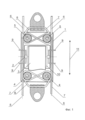
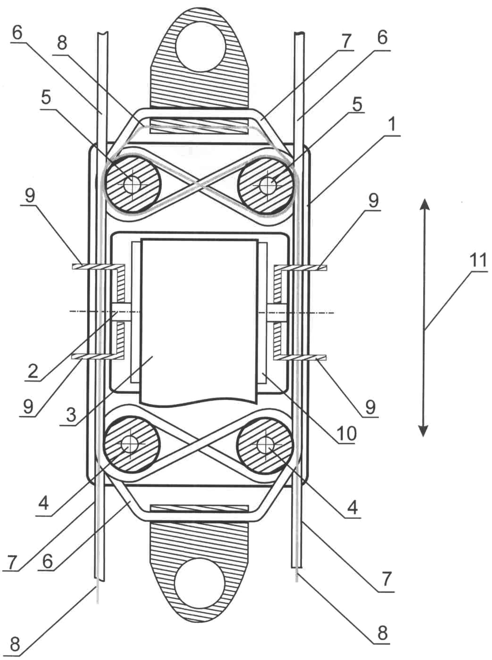
- фигура 1 схематично изображает общий вид энергопоглощающего механизма устройства для защиты пользователя транспортного средства согласно полезной модели.- figure 1 schematically depicts a General view of the energy-absorbing mechanism of the device for protecting the user of the vehicle according to the utility model.
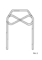
- фигура 2 схематично изображает один из деформируемых элементов согласно полезной модели.- figure 2 schematically depicts one of the deformable elements according to the utility model.
Как изображено на фигуре 1, энергопоглощающий механизм устройства для защиты пользователя транспортного средства, соединенный с креслом, ремнями безопасности и корпусом транспортного средства, содержит корпус 1 с направляющей осью 2 для ремня безопасности 3, первую 4 и вторую 5 пары деформирующих опор с двух сторон от направляющей оси 2, и деформируемые элементы первой 6 и второй 7 очередей срабатывания, со срединной частью, связанной, соответственно, с креслом (на фигурах не показано), с одной стороны и корпусом транспортного средства с другой (на фигурах не показано), и отогнутыми боковинами, зигзагом пропущенными соответственно через первые и вторые пары деформирующих опор 4 и 5. Деформируемые элементы первой 4 и второй 5 очереди срабатывания выполнены с одинаковыми усилиями торможения. Энергопоглощающий механизм устройства для защиты пользователя транспортного средства имеет дополнительный деформируемый элемент второй очереди срабатывания 8, рассчитанный на усилие притяга ремней безопасности 3. Энергопоглощающий механизм устройства для защиты пользователя транспортного средства имеет направляющие 9 на корпусе, в которых расположены концы деформируемых элементов 4, 5 и 8.As shown in figure 1, the energy-absorbing mechanism of the device for protecting the user of the vehicle, connected to the seat, seat belts and the vehicle body, includes a
Направляющая ось 2 обеспечивает скольжение ремня безопасности 3. Может быть дополнительно снабжена для увеличения проскальзывания роликом 10 (см. фиг 1).The
Деформируемые элементы могут быть выполнены проволочными, причем сечение проволоки может быть не обязательно круглым, он может быть квадратного, треугольного и проч. сечения с закругленными гранями. В зависимости от поставленных задач могут применяться разные оптимальные сечения. Вместо проволоки может использоваться, например, металлическая полоска.Deformable elements can be made wire, and the cross section of the wire may not necessarily be round, it can be square, triangular and so on. sections with rounded edges. Depending on the tasks, different optimal sections can be used. Instead of wire, for example, a metal strip can be used.
Деформируемые элементы первой очереди срабатывания в одном варианте могут быть связаны с креслом, в другом - с корпусом транспортного средства.Deformable elements of the first stage of operation in one embodiment can be associated with a chair, in another with a vehicle body.
При формулировании условия о том, что деформируемые элементы первой 4 и второй 5 очереди срабатывания выполнены с одинаковыми усилиями торможения, имеется в виду, что они могут быть одинаковыми по своим конструктивным параметрам - иметь одинаковое поперечное сечение, радиусы изгиба и прочее. В общем случае они могут иметь разные параметры, но, тем не менее, обеспечивать одинаковые усилия торможения.When formulating the condition that the deformable elements of the first 4 and second 5 response phases are made with the same braking forces, it is understood that they can be identical in their design parameters - have the same cross section, bending radii, and so on. In the general case, they can have different parameters, but, nevertheless, provide the same braking forces.
На фигуре 2 изображен деформирующий элемент 6 отдельно от всех остальных элементов, чтобы было видно, как он пропущен сквозь деформирующие опоры. Остальные деформирующие элементы выполнены точно также, только деформирующий элемент 7 расположен симметрично деформирующему элементу 6 относительно направляющей оси 2.The figure 2 shows the
Концы деформируемых элементов 6, 7 и 8 прямолинейны и не изогнуты. Концы деформируемых элементов первой 6 и второй 7 очередей направлены в противоположных направлениях. Их длина определяется величиной протяжки привязных ремней (первая очередь срабатывания) и полной величиной амортизационного хода (вторая очередь срабатывания).The ends of the
Концы деформируемых элементов первой 6 и второй 7 очередей срабатывания расположены навстречу друг другу параллельно оси движения 11 энергопоглощающего механизма устройства для защиты пользователя транспортного средства.The ends of the deformable elements of the first 6 and second 7 response queues are arranged towards each other parallel to the axis of
Энергопоглощающий механизм устройства для защиты пользователя транспортного средства работает следующим образом.The energy-absorbing mechanism of the device for protecting the user of the vehicle operates as follows.
В начале действия ударных инерционных нагрузок, например, при аварийном приземлении самолета, падении, взрыве или ударе, происходит деформация деформируемого элемента первой очереди срабатывания 6. При этом вне зависимости от действий экипажа происходит притяг ремней безопасности 3 до заранее заданного усилия. После достижения заданного усилия притяга ремней безопасности 3 происходит прекращение дальнейшего притяга и происходит деформация основного 7 и дополнительного 8 деформируемых элементов второй очереди срабатывания. При этом притягивание верхней части туловища человека в правильное положение с плотным примыканием спины к спинке устройства уже является обеспеченным, и дальнейшая деформация деформируемого основного 7 и дополнительного 8 деформируемых элементов второй очереди срабатывания приводит к перемещению кресла относительно кабины и поглощение энергии удара или взрыва происходит за счет деформации основного и дополнительного деформируемых элементов второй очереди срабатывания, и не происходит дальнейшего увеличения усилий фиксации и возможного травмирования пользователя транспортного средства. В тоже время, переносимость перегрузок человеком будет высокой.At the beginning of the action of inertial shock loads, for example, during an emergency landing of an airplane, falling, exploding, or impacting, the deformable element of the first
В соответствии с предложенной полезной моделью заявителем были изготовлены оригинальные опытные образцы энергопоглощающего механизма устройства для защиты пользователя транспортного средства, которые успешно прошли испытания на базе Института Авиационной и Космической Медицины и доказали свою эффективность. Получены результаты, подтверждающие наивысшую безопасность притяга привязных ремней и характеристик амортизационного хода.In accordance with the proposed utility model, the applicant produced original prototypes of the energy-absorbing mechanism of the device for protecting the vehicle user, which were successfully tested at the Institute of Aviation and Space Medicine and proved to be effective. The results are obtained, confirming the highest safety of the seat belt pull-up and the characteristics of the depreciation course.
Испытания опытного образца энергопоглощающего механизма устройства для защиты пользователя транспортного средства показали:Tests of the prototype of the energy-absorbing mechanism of the device for protecting the user of the vehicle showed:
- применение дополнительного деформируемого элемента второй очереди срабатывания позволяет точно рассчитать усилие притяга ремней безопасности и изготовить энергопоглощающий механизм устройства для защиты пользователя транспортного средства с безопасным усилием притяга;- the use of an additional deformable element of the second triggering stage allows you to accurately calculate the force of the seat belt tightening and to manufacture an energy-absorbing mechanism of the device to protect the user of the vehicle with a safe pull force;
- применение направляющих на корпусе, в которых расположены концы деформируемых элементов, обеспечивает постоянство зоны изгиба деформируемых элементов первой и второй очереди срабатывания относительно деформирующих элементов;- the use of guides on the body, in which the ends of the deformable elements are located, ensures the constancy of the bending zone of the deformable elements of the first and second response phases relative to the deforming elements;
- при вертикальной перегрузке торможения на кресле 15-17 g усилия притяга по каждому плечевому ремню составляли 50-70 кг при перемещении ремня 100-150 мм, что обеспечивает безопасность пользователя транспортного средства.- with a vertical overload of braking on a seat of 15-17 g, the pull-in forces for each shoulder belt were 50-70 kg when moving the belt 100-150 mm, which ensures the safety of the vehicle user.
Таким образом, в данной полезной модели достигнута поставленная задача - повышение безопасности пользователя транспортного средства.Thus, in this utility model, the task achieved is to increase the safety of the vehicle user.
Энергопоглощающий механизм устройства для защиты пользователя транспортного средства может быть использован для для защиты экипажа и пассажиров воздушных и наземных транспортных средств при авариях, а также при защите людей внутри сухопутной военной техники при минном подрыве.The energy-absorbing mechanism of the device to protect the user of the vehicle can be used to protect the crew and passengers of air and ground vehicles in case of accidents, as well as to protect people inside land military equipment during mine detonation.
Claims (2)
Priority Applications (1)
| Application Number | Priority Date | Filing Date | Title |
|---|---|---|---|
| RU2012141504/11U RU123740U1 (en) | 2012-09-28 | 2012-09-28 | ENERGY-ABSORBING DEVICE MECHANISM FOR PROTECTING A VEHICLE USER |
Applications Claiming Priority (1)
| Application Number | Priority Date | Filing Date | Title |
|---|---|---|---|
| RU2012141504/11U RU123740U1 (en) | 2012-09-28 | 2012-09-28 | ENERGY-ABSORBING DEVICE MECHANISM FOR PROTECTING A VEHICLE USER |
Publications (1)
| Publication Number | Publication Date |
|---|---|
| RU123740U1 true RU123740U1 (en) | 2013-01-10 |
Family
ID=48807298
Family Applications (1)
| Application Number | Title | Priority Date | Filing Date |
|---|---|---|---|
| RU2012141504/11U RU123740U1 (en) | 2012-09-28 | 2012-09-28 | ENERGY-ABSORBING DEVICE MECHANISM FOR PROTECTING A VEHICLE USER |
Country Status (1)
| Country | Link |
|---|---|
| RU (1) | RU123740U1 (en) |
Cited By (2)
| Publication number | Priority date | Publication date | Assignee | Title |
|---|---|---|---|---|
| RU2653347C1 (en) * | 2017-08-28 | 2018-05-07 | Общество с ограниченной ответственностью "АэроТакси-Сервис" | Vehicle chair |
| RU2775959C1 (en) * | 2021-10-21 | 2022-07-12 | Российская Федерация, от имени которой выступает Министерство обороны РФ | Mine resistant driver seat |
-
2012
- 2012-09-28 RU RU2012141504/11U patent/RU123740U1/en active
Cited By (4)
| Publication number | Priority date | Publication date | Assignee | Title |
|---|---|---|---|---|
| RU2653347C1 (en) * | 2017-08-28 | 2018-05-07 | Общество с ограниченной ответственностью "АэроТакси-Сервис" | Vehicle chair |
| RU2786463C1 (en) * | 2021-10-20 | 2022-12-21 | Российская Федерация от имени которой выступает Министерство обороны РФ | Anti-mine seat of the track vehicle operator |
| RU2775959C1 (en) * | 2021-10-21 | 2022-07-12 | Российская Федерация, от имени которой выступает Министерство обороны РФ | Mine resistant driver seat |
| RU2781532C1 (en) * | 2021-10-21 | 2022-10-13 | Российская Федерация, от имени которой выступает Министерство обороны РФ | Vehicle anti-mine seat damper |
Similar Documents
| Publication | Publication Date | Title |
|---|---|---|
| US4423848A (en) | Crashworthy helicopter seat | |
| KR101653308B1 (en) | An anti-crash seat and an aircraft | |
| US4408738A (en) | Variable energy absorbing system for crashworthy helicopter seats | |
| EP2570299A1 (en) | Child safety seat for vehicle | |
| US9988009B2 (en) | Separated anti-collision car | |
| US6381758B1 (en) | Head restraint system for racecar drivers | |
| EP1888940A1 (en) | Shock absorber | |
| RU123740U1 (en) | ENERGY-ABSORBING DEVICE MECHANISM FOR PROTECTING A VEHICLE USER | |
| CN107199986A (en) | A kind of energy absorption device and method for child safety seat restraint strap | |
| US20120273649A1 (en) | Shock absorbing device | |
| CN203094444U (en) | Safety protection type wheel power umbrella | |
| DE102004007171A1 (en) | Impact absorbing mounting for passenger seat especially in passenger vehicle has floor mounted support rails with integral springs | |
| US10513241B2 (en) | Compact force limiter for automotive safety restraints | |
| RU2448848C1 (en) | Shock-absorbing seat for transport facility | |
| RU2532983C1 (en) | Combat vehicle or aircraft seat (versions) | |
| US9709121B2 (en) | Twin wire bending kinetic energy attenuation system | |
| RU122618U1 (en) | DEVICE FOR PROTECTING THE USER OF THE VEHICLE | |
| CN109910815A (en) | A safety belt mandatory wearing device | |
| CN204394822U (en) | A kind of emergency tender being provided with multistage protection bumper | |
| RU2555871C1 (en) | Impact protection device of vehicle with passive damping system | |
| RU2653347C1 (en) | Vehicle chair | |
| US9724547B2 (en) | Standing vehicle occupant restraint system | |
| CN209852127U (en) | Seat cushioning energy-absorbing device | |
| EP3572324A1 (en) | Collapsible structure with varying stiffness-based energy attenuation system | |
| CN110667445B (en) | Seat lightning protection subassembly and vehicle that has it |