RU123789U1 - FLEXIBLE CONCRETE MAT WITH BEND FIXING (OPTIONS) - Google Patents
FLEXIBLE CONCRETE MAT WITH BEND FIXING (OPTIONS) Download PDFInfo
- Publication number
- RU123789U1 RU123789U1 RU2012140228/13U RU2012140228U RU123789U1 RU 123789 U1 RU123789 U1 RU 123789U1 RU 2012140228/13 U RU2012140228/13 U RU 2012140228/13U RU 2012140228 U RU2012140228 U RU 2012140228U RU 123789 U1 RU123789 U1 RU 123789U1
- Authority
- RU
- Russia
- Prior art keywords
- monolithic
- concrete blocks
- metal element
- concrete
- partially
- Prior art date
Links
Images

Landscapes
- Revetment (AREA)
Abstract
1. Гибкий бетонный мат, содержащий бетонные блоки, соединенные между собой порядно и в рядах с зазором замоноличенным канатом, отличающийся тем, что содержит, по меньшей мере, два металлических элемента, частично замоноличенных в бетонных блоках и выполненных с возможностью создания сварного соединения с дополнительным общим жестким металлическим элементом для фиксации их взаимного положения, причем замоноличенные металлические элементы соединены с бетонными блоками так, что способны выдержать не менее чем двукратный вес бетонного блока.2. Мат по п.1, отличающийся тем, что частично замоноличенный металлический элемент выполнен в виде пластины, или уголка, или швеллера, или стержня, или скобы.3. Мат по п.1, отличающийся тем, что частично замоноличенный металлический элемент имеет толщину от 1,5 мм до 5 мм и длину и/или ширину не менее 10 мм в своей пезамоноличенной части.4. Мат по любому из пп.1-3, отличающийся тем, что частично замоноличенный металлический элемент выступает над поверхностью блока не более чем на 35 мм или расположен вровень с поверхностью блока или утоплен в нее.5. Гибкий бетонный мат, содержащий бетонные блоки, соединенные между собой порядно и в рядах с зазором замоноличенным канатом, отличающийся тем, что содержит, по меньшей мере, две металлические пластины, частично замоноличенные в соседних бетонных блоках, причем пластины имеют толщину от 1,5 мм до 5 мм, длину и ширину незамоноличенной части не менее 10 мм, а взаимное положение бетонных блоков зафиксировано посредством, по меньшей мере, одного жесткого металлического элемента, приваренного к замоноличенным пластинам.6. Гибкий бетонный мат по п.5, отли1. A flexible concrete mat containing concrete blocks interconnected in order and in rows with a gap of a monolithic rope, characterized in that it contains at least two metal elements, partially monolithic in concrete blocks and made with the possibility of creating a welded joint with an additional a common rigid metal element for fixing their relative position, and monolithic metal elements are connected to concrete blocks so that they can withstand at least twice the weight of the concrete block Ka.2. Mat according to claim 1, characterized in that the partially monolithic metal element is made in the form of a plate, or a corner, or a channel, or a rod, or a bracket. Mat according to claim 1, characterized in that the partially monolithic metal element has a thickness of from 1.5 mm to 5 mm and a length and / or width of at least 10 mm in its pseudo-monolithic part. Mat according to any one of claims 1 to 3, characterized in that the partially monolithic metal element protrudes above the block surface by no more than 35 mm or is flush with the block surface or recessed into it. A flexible concrete mat containing concrete blocks interconnected in order and in rows with a gap of a monolithic rope, characterized in that it contains at least two metal plates partially monolithic in adjacent concrete blocks, the plates having a thickness of 1.5 mm or more up to 5 mm, the length and width of the non-core part is at least 10 mm, and the relative position of the concrete blocks is fixed by means of at least one rigid metal element welded to the monofilled plates. 6. The flexible concrete mat according to claim 5,
Description
Полезная модель относится к гидротехническому строительству, а именно к гидротехническим сооружениям, предназначенным для укрепления берегов, дамб, русел и поверхностей иных объектов. В частности, устройство может быть использовано при возведении подводных переходов трубопроводов, для защиты опор мостов, гребней плотин и дамб от размыва при переливе воды, при сооружении каналов, канав и стоков. Также устройство может быть использовано для защиты наземных покрытий, например в дорожном строительстве.The utility model relates to hydraulic engineering, namely to hydraulic structures intended to strengthen the banks, dams, channels and surfaces of other objects. In particular, the device can be used in the construction of underwater crossings of pipelines, to protect the supports of bridges, crests of dams and dams from erosion during water overflow, during the construction of canals, ditches and drains. Also, the device can be used to protect ground coatings, for example in road construction.
В области гидротехники известны различные конструкции гибких бетонных матов (ГБМ), применяемых для защиты разнообразных объектов от воздействия потока воды. Наибольшее распространение нашли ГБМ, содержащие бетонные блоки, соединенные между собой порядно и в рядах с зазором замоноличенным канатом. Бетонные блоки представляют собой двухсторонние усеченные пирамиды, соединенные между собой по плоскости общего большего основания в единый монолитный бетонный блок.In the field of hydraulic engineering, various designs of flexible concrete mats (GBM) are known that are used to protect a variety of objects from the effects of water flow. GBMs containing concrete blocks found interconnected in order and in rows with a gap with a monolithic rope found the greatest distribution. Concrete blocks are bilateral truncated pyramids, interconnected along the plane of a common larger base into a single monolithic concrete block.
На ГБМ действует ряд сил. Если под воздействием речного потока горизонтальная сила лобового сопротивления будет превосходить суммарную силу трения и силу пассивного отпора грунта, то произойдет отрыв бетонного блока от дна водотока, скручивание и дрейф полотна ГБМ в потоке воды. Данного явления необходимо избегать как в строительный, так и в эксплуатационный периоды.A number of forces act on the GBM. If, under the influence of the river flow, the horizontal drag force will exceed the total frictional force and the passive resistance force of the soil, then the concrete block will detach from the bottom of the watercourse, twisting and drift of the GBM canvas in the water stream. This phenomenon must be avoided both in the construction and operational periods.
Из описания полезной модели по патенту РФ №106629 (МПК Е02В 3/12, 20.07.2011) известен ГБМ, содержащий бетонные блоки, соединенные между собой порядно и в рядах с зазором замоноличенным канатом. В известном техническом решении бетонные блоки выполнены с хрупкими окантовками, которые перекрывают зазоры между соседними блоками ГБМ, что обеспечивает высокую степень защиты поверхности. После размещения на защищаемой поверхности известного ГБМ, под воздействием внешних факторов возможно смещение бетонных блоков относительно друг друга, в результате чего произойдет излишнее разрушение хрупких окантовок, зазор между соседними бетонными блоками увеличится, а следовательно возрастет опасность вымывания грунта из под ГБМ, снизится эффективность защиты поверхности.From the description of the utility model according to the patent of the Russian Federation No. 106629 (IPC Е02В 3/12, 07/20/2011), GBM is known that contains concrete blocks interconnected in order and in rows with a gap of a monolithic rope. In a known technical solution, concrete blocks are made with brittle edging that overlaps the gaps between adjacent GBM blocks, which provides a high degree of surface protection. After placing a known GBM on a protected surface, under the influence of external factors, concrete blocks can shift relative to each other, resulting in unnecessary destruction of brittle edging, the gap between adjacent concrete blocks will increase, and therefore the risk of soil washing out from under GBM will increase, the surface protection efficiency will decrease .
Задачей настоящей полезной модели является повышение защитных свойств ГБМ.The objective of this utility model is to increase the protective properties of GBM.
Обеспечиваемый полезной моделью технический результат заключается в исключении произвольных смещений бетонных блоков относительно друг друга после размещения ГБМ на защищаемой поверхности, при сохранении простоты технологии строительных работ. Исключение произвольных смещений бетонных блоков ГБМ относительно друг друга препятствует смещению ГБМ и увеличению зазора между его бетонными блоками, что ведет к повышению защитных свойств ГБМ.The technical result provided by the utility model consists in eliminating arbitrary displacements of concrete blocks relative to each other after placing the GBM on the protected surface, while maintaining the simplicity of the construction work technology. The exclusion of arbitrary displacements of concrete blocks of GBM relative to each other prevents the displacement of GBM and an increase in the gap between its concrete blocks, which leads to an increase in the protective properties of GBM.
Технический результат достигается благодаря тому, что ГБМ, содержащий бетонные блоки, соединенные между собой порядно и в рядах с зазором замоноличенным канатом, также содержит, по меньшей мере, два металлических элемента, частично замоноличенных в бетонных блоках. При этом частично замоноличенные металлические элементы выполнены с возможностью создания сварного соединения с дополнительным общим жестким металлическим элементом для фиксации их взаимного положения. Причем замоноличенные металлические элементы соединены с бетонными блоками так, что способны выдержать не менее, чем двукратный вес бетонного блока.The technical result is achieved due to the fact that the GBM, containing concrete blocks, interconnected in order and in rows with a gap of a monolithic rope, also contains at least two metal elements partially monolithic in concrete blocks. In this case, partially monolithic metal elements are configured to create a welded joint with an additional common rigid metal element to fix their relative position. Moreover, monolithic metal elements are connected to concrete blocks so that they can withstand at least twice the weight of the concrete block.
В частном случае выполнения ГБМ, частично замоноличещ1ый металлический элемент выполнен в виде пластины или уголка или швеллера или стержня или скобы.In the particular case of performing the GBM, a partially monolithic metal element is made in the form of a plate or corner or channel or rod or bracket.
В другом частном случае, частично замоноличенный металлический элемент имеет толщину от 1,5 мм до 5 мм и длину и/или ширину не менее 10 мм в своей незамоноличенной части.In another particular case, a partially monolithic metal element has a thickness of from 1.5 mm to 5 mm and a length and / or width of at least 10 mm in its non-monolithic part.
В еще одном частном случае, частично замоноличенпый металлический элемент выступает над поверхностью блока не более чем на 35 мм или расположен вровень с поверхностью блока или утоплен в нее.In another particular case, a partially monolithic metal element protrudes above the block surface by no more than 35 mm or is located flush with the block surface or recessed into it.
Также технический результат достигается благодаря тому, что ГБМ, содержащий бетонные блоки, соединенные между собой порядно и в рядах с зазором замоноличенным канатом, содержит также, по меньшей мере, две металлические пластины, частично замоноличенные в соседних бетонных блоках. Причем пластины имеют толщину от 1,5 мм до 5 мм, длину и ширину незамоноличенной части не менее 10 мм, а взаимное положение бетонных блоков зафиксировано посредством, по меньшей мере, одного жесткого металлического элемента, приваренного к замоноличенным пластинам.Also, the technical result is achieved due to the fact that the GBM, containing concrete blocks interconnected in order and in rows with a gap with a monopolized rope, also contains at least two metal plates partially monolithic in adjacent concrete blocks. Moreover, the plates have a thickness of 1.5 mm to 5 mm, the length and width of the non-core part is not less than 10 mm, and the relative position of the concrete blocks is fixed by means of at least one rigid metal element welded to the monofilled plates.
В частном случае данного варианта ГБМ жесткий металлический элемент представляет собой прямой или изогнутый стержень или пластину.In the particular case of this embodiment, the GBM rigid metal element is a straight or curved rod or plate.
Полезная модель иллюстрируется следующими графическими материалами.The utility model is illustrated by the following graphic materials.
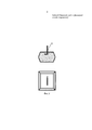
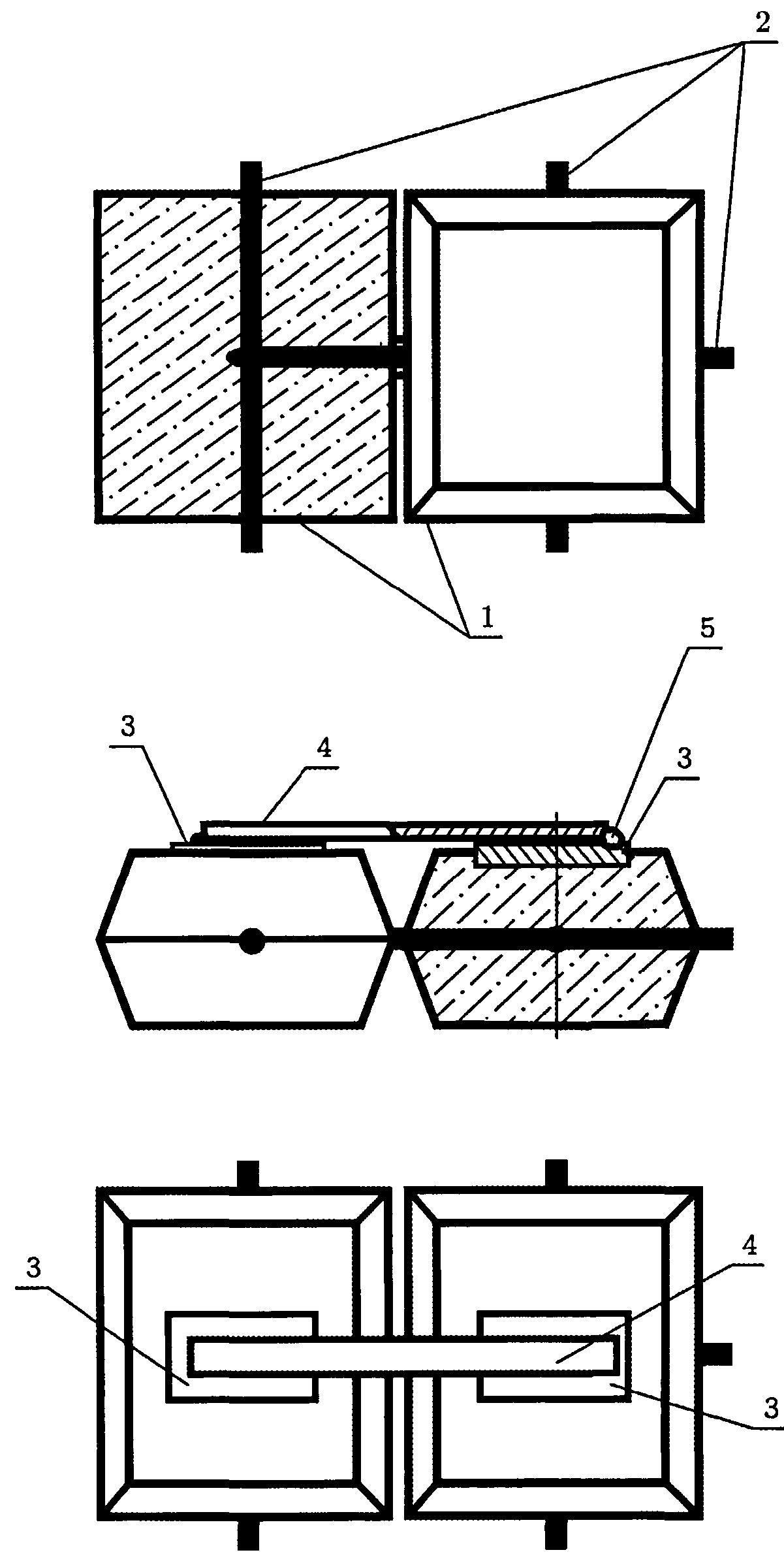
На фиг.1 изображен фрагмент краевой части ГБМ, вид снизу, спереди и сверху.Figure 1 shows a fragment of the edge of the GBM, a view from below, front and top.
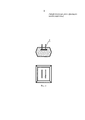
На фиг.2 представлен бетонный блок в разрезе с замоноличенным уголком.Figure 2 presents a concrete block in section with a monolithic corner.
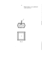
На фиг.3 изображен бетонный блок в разрезе с замоноличенным швеллером.Figure 3 shows a concrete block in section with monolithic channel.
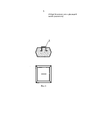
На фиг.4 показан бетонный блок с замоноличенным стержнем.Figure 4 shows a concrete block with monolithic rod.
На фиг.5 представлен бетонный блок с замоноличенной скобой.Figure 5 presents a concrete block with monolithic bracket.
Полезная модель осуществляется следующим образом.The utility model is as follows.
В первом варианте своего выполнения ГБМ содержит бетонные блоки 1, соединенные между собой порядно и в рядах с зазором замоноличенным канатом 2. Соседних бетонных блоках 1 частично замоноличены металлические элементы 3. Данные металлические элементы 3 выполнены так, чтобы к ним можно было приварить дополнительный общий жесткий металлический элемент 4. Сварное соединение 5 обеспечивает фиксацию взаимного положения металлических элементов 3, а следовательно и бетонных блоков 1, при условии жесткости металлического элемента 4, надежного соединения металлических элементов 3 с бетонными блоками 1 и достаточной прочности сварного соединения 5. Причем бетонные блоки 1 не обязательно должны быть расположены вблизи друг от друга, при достаточной длине и жесткости металлического элемента 4.In the first embodiment, the GBM contains
Соединение металлических элементов 3 с бетонными блоками 1 можно признать достаточно надежным, если замоноличенные металлические элементы 3 соединены с бетонными блоками 1 так, что способны выдержать не менее, чем двукратный вес бетонного блока 1. При этом исключается возможность вырывания металлического элемента 3 из бетонного блока 1 под действием собственного веса бетонных блоков 1.The connection of
Для создания необходимой прочности сварного соединения 5 частично замоноличенный металлический элемент должен иметь толщину от 1,5 мм до 5 мм и длину и/или ширину не менее 10 мм в своей незамоноличенной части.To create the necessary strength of the
Для частичной фиксации изгиба ГБМ необходимо жестко связать между собой как минимум два блока 1 ГБМ. Чем большее число бетонных блоков будет зафиксировано, тем сильнее будут повышены защитные свойства ГБМ, благодаря тому, что практически станут невозможными смещения ГБМ по отношению к защищаемой поверхности и увеличение открытого пространства между блоками ГБМ.For partial fixation of the GBM bend, at least two blocks of 1 GBM must be rigidly connected. The more concrete blocks are fixed, the stronger the protective properties of the GBM will be enhanced, due to the fact that it becomes practically impossible to displace the GBM in relation to the protected surface and increase the open space between the GBM blocks.
Благодаря тому, что элементы 3 являются металлическими и замоноличены в бетонных блоках 1 только частично, их можно быстро и жестко связать между собой через дополнительный общий жесткий металлический элемент 4 при помощи обычной сварки, что позволяет обойтись без существенного усложнения монтажной технологии строительных работ.Due to the fact that the
ГБМ с бетонными блоками 1 нужной формы изготовляют с использованием формообразующей оснастки в виде основания и крышки, в которой укладывают и закрепляют соединительный канат 2. Затем оснастку заполняют жидкой бетонной смесью. Во время изготовления ГБМ в выбранный бетонный блок 1 замоноличивают металлический элемент 3 или большее их число, в зависимости от конкретных условий.GBM with
Полезная модель может быть осуществлена с различными вариантами выполнения металлических элементов 3.The utility model can be implemented with various options for the execution of
Металлический элемент 3 выполняют в виде пластины квадратной или прямоугольной в плане формы (фиг.1), уголка 6 (фиг.2), П-образного швеллера 7 (фиг.3), стержня 8 (фиг.4), скобы 9 (фиг.5) или иной подходящей формы.The
Для лучшего сцепления с бетоном нижнюю часть пластины желательно оставлять неровной, а стержень или скобу выполнять с изгибами в нижней части.For better adhesion to concrete, it is desirable to leave the lower part of the plate uneven, and to perform the rod or bracket with bends in the lower part.
Выбор данных форм металлических элементов 3 обусловлен тем, что элементы всех перечисленных форм могут быть как надежно замоноличены в бетонные блоки 1, так и иметь свободную поверхность своей незамополиченной части, достаточную для выполнения надежного сварного соединения 5.The choice of these forms of
К вертикальной полке уголка 6 или швеллера 7 более удобно, чем к горизонтально расположенной пластине, приваривать под углом жесткий металлический элемент 4, который затруднительно изогнуть в случае большой его толщины. Форма металлических элементов 3 в виде скобы 9 позволяет создать очень прочное соединение, так как жесткий металлический элемент 4 можно предварительно пропустить под скобу 9, которая будет воспринимать основное усилие по отрыву жесткого металлического элемента 4, и только потом зафиксировать его сваркой. Стержень 8 можно при необходимости изгибать в нужную сторону.It is more convenient to the vertical shelf of the
Если металлический элемент 3, например, уголок 6 или стержень 8, выступает над поверхностью блока 1 не более чем на 35 мм, то его высоты достаточно для создания надежного сварного соединения 5 без перерасхода металла.If a
После окончания сварочных работ лишнюю выступающую часть пластины, уголка, швеллера или стержня целесообразно срезать, в противном случае за ГБМ будут цепляться проплывающие предметы. Срезать выступающие части металлического элемента 3 не требуется, если он расположен вровень с поверхностью блока 1 или утоплен в нее.After completion of welding work, it is advisable to cut off the excess protruding part of the plate, corner, channel or rod, otherwise floating objects will cling to the GBM. Cutting off the protruding parts of the
Предпочтительным является вариант ГБМ, в котором бетонные блоки 1, соединены между собой порядно и в рядах с зазором замоноличенным канатом 2, а металлические пластины 3 частично замоноличены в соседних бетонных блоках 1. Причем пластины имеют толщину от 1,5 мм до 5 мм, длину и ширину своей незамоноличенной части не менее 10 мм, а взаимное положение бетонных блоков зафиксировано посредством по меньшей мере одного жесткого металлического элемента 4, приваренного к замоноличенным пластинам 3.GBM is preferred, in which the
Пластина 3 указанного размера надежно удерживается в бетонном блоке 1 и одновременно с этим хорошо подходит для приваривапия к ней конца жесткого металлического элемента 4, имея для создания прочного сварного соединения 5 достаточную площадь своей поверхности.The
Жесткий металлический элемент 4 предпочтительно представляет собой прямой или изогнутый стержень или толстую пластину.The
Выполнение ГБМ по любому из своих вариантов не ограничивает его гибкость при транспортировке, а также укладке на защищаемую поверхность, и позволяет после укладки, когда ГБМ занял рабочее положение, повторив форму защищаемой поверхности, зафиксировать взаимное расположение бетонных блоков, их взаимный изгиб, для исключения произвольных смещений бетонных блоков относительно друг друга. Кроме того, в случае замоноличивания металлических элементов в угловых бетонных блоках ГБМ, данные металлические элементы могут быть использованы для скрепления двух или более ГБМ между собой.The performance of the GBM according to any of its options does not limit its flexibility during transportation, as well as laying on a protected surface, and allows, after laying, when the GBM has taken its working position, repeating the shape of the protected surface, to fix the relative position of concrete blocks, their mutual bending, to exclude arbitrary displacements of concrete blocks relative to each other. In addition, in the case of monolithic metal elements in the corner concrete blocks of GBM, these metal elements can be used to bond two or more GBM to each other.
Claims (6)
Priority Applications (1)
| Application Number | Priority Date | Filing Date | Title |
|---|---|---|---|
| RU2012140228/13U RU123789U1 (en) | 2012-09-20 | 2012-09-20 | FLEXIBLE CONCRETE MAT WITH BEND FIXING (OPTIONS) |
Applications Claiming Priority (1)
| Application Number | Priority Date | Filing Date | Title |
|---|---|---|---|
| RU2012140228/13U RU123789U1 (en) | 2012-09-20 | 2012-09-20 | FLEXIBLE CONCRETE MAT WITH BEND FIXING (OPTIONS) |
Publications (1)
| Publication Number | Publication Date |
|---|---|
| RU123789U1 true RU123789U1 (en) | 2013-01-10 |
Family
ID=48807346
Family Applications (1)
| Application Number | Title | Priority Date | Filing Date |
|---|---|---|---|
| RU2012140228/13U RU123789U1 (en) | 2012-09-20 | 2012-09-20 | FLEXIBLE CONCRETE MAT WITH BEND FIXING (OPTIONS) |
Country Status (1)
| Country | Link |
|---|---|
| RU (1) | RU123789U1 (en) |
Cited By (1)
| Publication number | Priority date | Publication date | Assignee | Title |
|---|---|---|---|---|
| RU2739775C1 (en) * | 2020-06-05 | 2020-12-28 | Николай Николаевич Кириллов | Flexible web of concrete blocks |
-
2012
- 2012-09-20 RU RU2012140228/13U patent/RU123789U1/en active
Cited By (1)
| Publication number | Priority date | Publication date | Assignee | Title |
|---|---|---|---|---|
| RU2739775C1 (en) * | 2020-06-05 | 2020-12-28 | Николай Николаевич Кириллов | Flexible web of concrete blocks |
Similar Documents
| Publication | Publication Date | Title |
|---|---|---|
| RU123789U1 (en) | FLEXIBLE CONCRETE MAT WITH BEND FIXING (OPTIONS) | |
| JP2016079646A (en) | Revetment structure | |
| RU105312U1 (en) | CONCRETE BLOCK AND FLEXIBLE MAT FROM CONCRETE BLOCKS | |
| CN210857112U (en) | Hidden water conservancy slope protection structure | |
| CN103088992A (en) | Floating floor slab of high-rise building large scale device and construction method | |
| AU2015218075A1 (en) | A dam | |
| RU2503773C1 (en) | Flexible concrete mat with fixation of bend (versions) | |
| RU112213U1 (en) | FLEXIBLE PROTECTIVE CONCRETE COATING | |
| JP4955827B1 (en) | Horizontal piles for waterproof piles and main piles | |
| CN201588402U (en) | Side form for forming construction joints or post-casting strips | |
| JP5673392B2 (en) | High rigidity steel sheet pile and wall | |
| CN203807954U (en) | Box girder strengthening structure based on steel plate-concrete and unbonded pre-stressing tendons | |
| KR101251602B1 (en) | Pollution protection fence fix device by rock sack | |
| CN203462461U (en) | Arch-shaped prestressed reinforced concrete soldier pile | |
| JP2016141944A (en) | dam | |
| CN210597199U (en) | Ecological bank protection in gardens | |
| RU2528191C1 (en) | Modular coast protection structure | |
| RU138163U1 (en) | HIDDEN MOUNTED CONCRETE MAT AND FLEXIBLE PROTECTIVE CANVAS | |
| CN104389291B (en) | Rapid construction dock structure and construction method thereof on a kind of soft soil foundation | |
| CN203113312U (en) | Steel sheet pile | |
| CN214116306U (en) | Bent cap reinforcing bar bed-jig and bridge construction equipment | |
| CN208346755U (en) | A kind of river levee anti-impact shore protection | |
| RU170657U1 (en) | REVETMENT | |
| JP7510652B1 (en) | Supporting member | |
| RU2317369C1 (en) | Method for river bank consolidation |
Legal Events
| Date | Code | Title | Description |
|---|---|---|---|
| QB1K | Licence on use of utility model |
Free format text: LICENCE Effective date: 20140312 |
|
| QB1K | Licence on use of utility model |
Free format text: LICENCE Effective date: 20140528 |
|
| QB1K | Licence on use of utility model |
Free format text: LICENCE Effective date: 20140710 |
|
| QB1K | Licence on use of utility model |
Free format text: LICENCE Effective date: 20141205 |
|
| QB1K | Licence on use of utility model |
Free format text: LICENCE Effective date: 20150220 |
|
| QB1K | Licence on use of utility model |
Free format text: LICENCE Effective date: 20161130 |
|
| QB1K | Licence on use of utility model |
Free format text: LICENCE Effective date: 20161201 |
|
| QB1K | Licence on use of utility model |
Free format text: LICENCE Effective date: 20170621 |
|
| QB1K | Licence on use of utility model |
Free format text: LICENCE Effective date: 20170622 |
|
| QB1K | Licence on use of utility model |
Free format text: LICENCE Effective date: 20170629 |
|
| QB1K | Licence on use of utility model |
Free format text: LICENCE Effective date: 20170803 |