RU141237U1 - FIXER OF REINFORCED RODS FOR CREATION OF A PROTECTIVE CONCRETE LAYER - Google Patents
FIXER OF REINFORCED RODS FOR CREATION OF A PROTECTIVE CONCRETE LAYER Download PDFInfo
- Publication number
- RU141237U1 RU141237U1 RU2013158994/03U RU2013158994U RU141237U1 RU 141237 U1 RU141237 U1 RU 141237U1 RU 2013158994/03 U RU2013158994/03 U RU 2013158994/03U RU 2013158994 U RU2013158994 U RU 2013158994U RU 141237 U1 RU141237 U1 RU 141237U1
- Authority
- RU
- Russia
- Prior art keywords
- grooves
- concrete
- retainer
- reinforcing bar
- protective layer
- Prior art date
Links
- 239000004567 concrete Substances 0.000 title claims abstract description 16
- 230000001681 protective effect Effects 0.000 title 1
- 230000003014 reinforcing effect Effects 0.000 claims abstract description 24
- 239000011241 protective layer Substances 0.000 claims abstract description 13
- 239000000463 material Substances 0.000 description 6
- 238000009415 formwork Methods 0.000 description 4
- 230000015572 biosynthetic process Effects 0.000 description 1
- 238000010276 construction Methods 0.000 description 1
- 238000009434 installation Methods 0.000 description 1
- 239000010410 layer Substances 0.000 description 1
- 238000004519 manufacturing process Methods 0.000 description 1
- 239000011150 reinforced concrete Substances 0.000 description 1
Images
Landscapes
- Reinforcement Elements For Buildings (AREA)
Abstract
1. Фиксатор арматурных стержней для создания защитного слоя бетона, содержащий пластмассовый трубчатый корпус, на торцах которого выполнены диаметрально расположенные пазы одинаковой формы и глубины для укладки арматурного стержня, отличающийся тем, что на каждом торце трубчатого корпуса выполнено не менее четырех пазов, смежные из которых имеют разную глубину, а каждая пара диаметрально расположенных пазов на обоих торцах выполнена на различной глубине.2. Фиксатор арматурных стержней для создания защитного слоя бетона по п.1, отличающийся тем, что на поверхности пазов выполнены отверстия. 1. The reinforcing bar retainer for creating a protective layer of concrete, containing a plastic tubular body, at the ends of which are made diametrically grooves of the same shape and depth for laying the reinforcing bar, characterized in that at least four grooves are made at each end of the tubular body, adjacent of which have different depths, and each pair of diametrically located grooves at both ends is made at different depths. 2. The reinforcing bar retainer for creating a protective layer of concrete according to claim 1, characterized in that holes are made on the surface of the grooves.
Description
Полезная модель относится к области строительства и касается конструкций для фиксации арматурных стержней для обеспечения заданной толщины защитного слоя бетона при изготовлении железобетонных изделий.The utility model relates to the field of construction and relates to structures for fixing reinforcing bars to ensure a given thickness of the protective layer of concrete in the manufacture of reinforced concrete products.
Известен фиксатор арматурных стержней для создания защитного слоя бетона, содержащий пластмассовый трубчатый корпус, на торцах которого выполнены диаметрально расположенные пазы одинаковой формы и глубины для укладки арматурного стержня (см. патент Великобритании №1276874, МПК E04C 5/20, публ. 1972 г.). К недостаткам известного фиксатора можно отнести большую материалоемкость и возможность надежной фиксации только двух арматурных стержней.Known retainer of reinforcing bars for creating a protective layer of concrete, containing a plastic tubular body, at the ends of which are made diametrically grooves of the same shape and depth for laying the reinforcing bar (see UK patent No. 1276874, IPC
Наиболее близким по технической сущности к предлагаемому является фиксатор арматурных стержней для создания защитного слоя бетона, содержащий пластмассовый трубчатый корпус, на торцах которого выполнены диаметрально расположенные пазы одинаковой формы и глубины для укладки арматурного стержня, (см. патент РФ на изобретение №2458216, МПК E04C 5/16, публ. 2012 г.). К недостаткам известного фиксатора можно отнести большую материалоемкость и возможность надежной фиксации на горизонтальном уровне арматурных стержней на двух различных высотах относительно основания корпуса фиксатора, что позволяет в дальнейшем сформировать защитные слоя бетона, имеющие только две различные толщиныThe closest in technical essence to the proposed one is a reinforcing bar retainer for creating a protective layer of concrete, containing a plastic tubular body, at the ends of which there are diametrically located grooves of the same shape and depth for laying the reinforcing bar (see RF patent for invention No. 2458216, IPC
Предлагаемая полезная модель направлена на решение задачи, состоящей в увеличении диапазона значений высот фиксации арматурных стержней относительно основания корпуса фиксатора и уменьшении материалоемкости.The proposed utility model is aimed at solving the problem of increasing the range of values of the fixing heights of the reinforcing bars relative to the base of the retainer housing and reducing the material consumption.
Данная задача решается тем, что в фиксаторе арматурных стержней для создания защитного слоя бетона, содержащем пластмассовый трубчатый корпус, на торцах которого выполнены диаметрально расположенные пазы одинаковой формы и глубины для укладки арматурного стержня, на каждом торце трубчатого корпуса выполнено не менее четырех пазов, смежные из которых имеют разную глубину, а каждая пара диаметрально расположенных пазов на обоих торцах выполнена на различной глубине.This problem is solved in that in the retainer of reinforcing bars to create a protective layer of concrete containing a plastic tubular body, at the ends of which are made diametrically grooves of the same shape and depth for laying the reinforcing bar, at least four grooves are made at each end of the tubular body adjacent to which have different depths, and each pair of diametrically located grooves at both ends is made at different depths.
При этом предпочтительно, чтобы на поверхности пазов были выполнены отверстия.Moreover, it is preferable that holes are made on the surface of the grooves.
Выполнение на каждом торце трубчатого корпуса не менее четырех пазов, смежные из которых имеют разную глубину, при том, что каждая пара диаметрально расположенных пазов на обоих торцах выполнена на различной глубине, то есть таким образом, чтобы в фиксаторе на обоих торцах вообще отсутствовали пары диаметрально расположенных пазов, имеющие одинаковую глубину, обеспечивает увеличение диапазона значений высот фиксации арматурных стержней относительно основания корпуса фиксатора, так как при этом имеется возможность фиксации для не менее, чем для четырех значений высот, на которых может быть осуществлена фиксация и, соответственно, для не менее чем четырех значений толщин защитного слоя бетона.The execution of at least four grooves on each end of the tubular body, adjacent of which have different depths, while each pair of diametrically spaced grooves on both ends is made at different depths, that is, so that there are no diametrically pairs in both ends of the retainer located grooves having the same depth, provides an increase in the range of values of the fixing heights of the reinforcing bars relative to the base of the retainer body, since it is possible to fix for at least Than for four values of the heights at which fixing and, respectively, for at least four values concrete protective layer thickness can be carried out.
Выполнение на поверхности пазов отверстий обеспечивает снижение материалоемкости фиксатора за счет отсутствия материала в полостях отверстий.The execution on the surface of the grooves of the holes reduces the material consumption of the retainer due to the lack of material in the cavities of the holes.
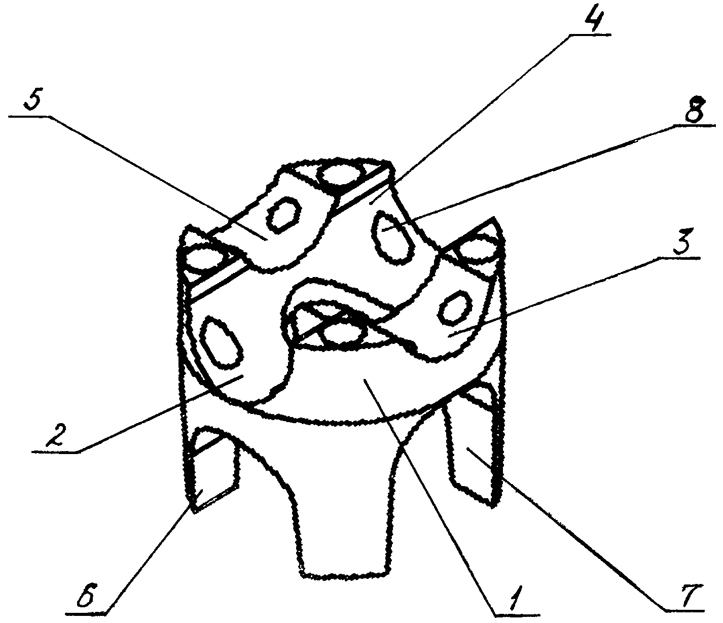
На чертеже представлен предлагаемый фиксатор арматурных стержней для создания защитного слоя бетона (вид в изометрии).The drawing shows the proposed fixture of reinforcing bars to create a protective layer of concrete (isometric view).
Фиксатор содержит пластмассовый трубчатый корпус 1, на каждом торце которого выполнено не менее четырех пазов, 2, 3, 4, 5 - на верхнем торце и 6, 7 и два других не видны на чертеже - на нижнем торце. Смежные пазы, например, 2 и 3, 4 и 5 имеют разную глубину, а диаметрально расположенные пазы, например, 2 и 4, 3 и 5, имеют одинаковую форму и глубину для укладки арматурного стержня. Каждая пара диаметрально расположенных пазов на обоих торцах выполнена на различной глубине, таким образом, что глубина каждой пары пазов отличается от глубины любой другой пары пазов фиксатора. На поверхности пазов выполнены отверстия 8, которые могут быть глухими или сквозными.The latch contains a plastic tubular body 1, at each end of which at least four grooves are made, 2, 3, 4, 5 at the upper end and 6, 7 and two others are not visible in the drawing at the lower end. Adjacent grooves, for example, 2 and 3, 4 and 5 have different depths, and diametrically located grooves, for example, 2 and 4, 3 and 5, have the same shape and depth for laying the reinforcing bar. Each pair of diametrically located grooves on both ends is made at different depths, so that the depth of each pair of grooves is different from the depth of any other pair of grooves of the retainer. Holes 8 are made on the surface of the grooves, which can be blind or through.
Фиксацию арматурных стержней осуществляют следующим образом.Fixing reinforcing bars is as follows.
В зависимости от необходимой толщины защитного слоя бетона на корпусе 1 фиксатора из всей совокупности пар диаметрально расположенных пазов, 2 и 4, 3 и 5, 6 и не показанный на чертеже диаметрально расположенный паз, 7 и не показанный на чертеже диаметрально расположенный паз, выбирается такая пара пазов, глубина которых позволяет установить арматурный стержень на опалубке на такой высоте, которая позволяет в дальнейшем получить заданную толщину слоя бетона. При этом, очевидно, корпус 1 фиксатора может устанавливаться на опалубку любым из торцов. Затем в выбранные пары пазов фиксаторов устанавливают арматурные стержни (не показаны) и заполняют опалубку бетонной смесью.Depending on the required thickness of the concrete protective layer on the fixture case 1, from the whole set of pairs of diametrically located grooves, 2 and 4, 3 and 5, 6 and a diametrically located groove not shown in the drawing, 7 and a diametrically located groove not shown in the drawing, such a pair of grooves, the depth of which allows you to install the reinforcing bar on the formwork at such a height that allows you to further obtain the specified thickness of the concrete layer. In this case, obviously, the housing 1 of the latch can be installed on the formwork by any of the ends. Then, reinforcing bars (not shown) are installed in the selected pairs of retainer slots and the formwork is filled with concrete.
Предлагаемый фиксатор арматурных стержней имеет небольшую материалоемкость и обеспечивает возможность фиксации в широком диапазоне значений высот установки арматурных стержней относительно основания корпуса фиксатора или опалубки, позволяя тем самым получить защитные слои бетона различной толщины.The proposed reinforcing bar retainer has a small material consumption and provides the ability to fix in a wide range of installation heights of the reinforcing bars relative to the base of the retainer body or formwork, thereby obtaining protective layers of concrete of various thicknesses.
Claims (2)
Priority Applications (1)
| Application Number | Priority Date | Filing Date | Title |
|---|---|---|---|
| RU2013158994/03U RU141237U1 (en) | 2013-12-31 | 2013-12-31 | FIXER OF REINFORCED RODS FOR CREATION OF A PROTECTIVE CONCRETE LAYER |
Applications Claiming Priority (1)
| Application Number | Priority Date | Filing Date | Title |
|---|---|---|---|
| RU2013158994/03U RU141237U1 (en) | 2013-12-31 | 2013-12-31 | FIXER OF REINFORCED RODS FOR CREATION OF A PROTECTIVE CONCRETE LAYER |
Publications (1)
| Publication Number | Publication Date |
|---|---|
| RU141237U1 true RU141237U1 (en) | 2014-05-27 |
Family
ID=50780312
Family Applications (1)
| Application Number | Title | Priority Date | Filing Date |
|---|---|---|---|
| RU2013158994/03U RU141237U1 (en) | 2013-12-31 | 2013-12-31 | FIXER OF REINFORCED RODS FOR CREATION OF A PROTECTIVE CONCRETE LAYER |
Country Status (1)
| Country | Link |
|---|---|
| RU (1) | RU141237U1 (en) |
-
2013
- 2013-12-31 RU RU2013158994/03U patent/RU141237U1/en not_active IP Right Cessation
Similar Documents
| Publication | Publication Date | Title |
|---|---|---|
| RU2554958C2 (en) | Light-conducting structural component for facilities and buildings and method of its manufacturing | |
| RU141237U1 (en) | FIXER OF REINFORCED RODS FOR CREATION OF A PROTECTIVE CONCRETE LAYER | |
| PL406281A1 (en) | Fish pass and the Method for making the fish pass | |
| WO2014125553A1 (en) | Floor panel and method for producing same | |
| RU133169U1 (en) | ELEMENT OF MONOLITHIC CONCRETE COVERING | |
| RU140550U1 (en) | FIXER OF REINFORCED RODS FOR CREATION OF A PROTECTIVE CONCRETE LAYER | |
| JP5946779B2 (en) | Cloth foundation | |
| RU155290U1 (en) | Armature Connector | |
| PL124495U1 (en) | Reinforced concrete prefabricated elements | |
| CN102605876B (en) | Brick wall structure | |
| RU157709U1 (en) | WALL UNIT | |
| MD677Y (en) | Earthquakeproof wall structure | |
| RU132814U1 (en) | REINFORCED REINFORCED CONCRETE FRAME | |
| KR102631611B1 (en) | Architectural exterior finishes | |
| KR101147468B1 (en) | Fabricated stepping-stones | |
| KR20090084568A (en) | Concrete block structures for civil wall construction | |
| RU151740U1 (en) | WALL WITH FIXED FORMWORK | |
| RU2458216C1 (en) | Fixator of reinforcement rods to create protective concrete layer | |
| RU141484U1 (en) | BAR SUPPORT | |
| RU2612203C1 (en) | Method of formation of mole drains | |
| PL126192U1 (en) | Formwork basket for mounting of a balcony slab | |
| RU150739U1 (en) | DEVICE FOR FIXING REINFORCED RODS | |
| RU146614U1 (en) | BRICK INSTRUMENT | |
| RU78243U1 (en) | SHIELDING FORM | |
| KR102105819B1 (en) | Fabricated stair type block assembly |
Legal Events
| Date | Code | Title | Description |
|---|---|---|---|
| MM9K | Utility model has become invalid (non-payment of fees) |
Effective date: 20180101 |