RU200098U1 - STEAM EMISSION SILENCER - Google Patents
STEAM EMISSION SILENCER Download PDFInfo
- Publication number
- RU200098U1 RU200098U1 RU2020101238U RU2020101238U RU200098U1 RU 200098 U1 RU200098 U1 RU 200098U1 RU 2020101238 U RU2020101238 U RU 2020101238U RU 2020101238 U RU2020101238 U RU 2020101238U RU 200098 U1 RU200098 U1 RU 200098U1
- Authority
- RU
- Russia
- Prior art keywords
- steam
- silencer
- noise
- sound
- blocks
- Prior art date
Links
Images
Classifications
-
- F—MECHANICAL ENGINEERING; LIGHTING; HEATING; WEAPONS; BLASTING
- F01—MACHINES OR ENGINES IN GENERAL; ENGINE PLANTS IN GENERAL; STEAM ENGINES
- F01N—GAS-FLOW SILENCERS OR EXHAUST APPARATUS FOR MACHINES OR ENGINES IN GENERAL; GAS-FLOW SILENCERS OR EXHAUST APPARATUS FOR INTERNAL-COMBUSTION ENGINES
- F01N1/00—Silencing apparatus characterised by method of silencing
- F01N1/08—Silencing apparatus characterised by method of silencing by reducing exhaust energy by throttling or whirling
- F01N1/10—Silencing apparatus characterised by method of silencing by reducing exhaust energy by throttling or whirling in combination with sound-absorbing materials
Landscapes
- Engineering & Computer Science (AREA)
- Chemical & Material Sciences (AREA)
- Combustion & Propulsion (AREA)
- Mechanical Engineering (AREA)
- General Engineering & Computer Science (AREA)
- Exhaust Silencers (AREA)
Abstract
Полезная модель относится к технологическим устройствам, механизм действия которых основан на ступенчатом дросселировании паровоздушной среды, с целью снижения ее скорости и изменения уровня звукового давления, генерируемого при выбросах пара в атмосферу на объектах энергетики.Задачей полезной модели является разработка глушителя шума выбросов пара, в котором устранены недостатки аналогичных устройств.Технический результатом является разработка глушителя шума выбросов пара, работающего на диапазоне частот 63,5-8000 Гц, имеющего малые габариты при работе в широкополосных диапазонах за счет установки дроссельных блоков, а также имеющего теплоизоляцию для исключения конденсации влаги и последующего ее замерзания на стенках аппарата.Технический результат достигается тем, что глушитель шума выбросов пара, имеющий цилиндрическую форму, состоящий из резонаторов, установленных в разрыве трубопровода отвода отходящих газов, при этом волны звука, распространяющиеся по акустическому прозрачному перфорированному трубопроводу в среде отходящих газов, возбуждают собственные колебания, согласно настоящей полезной модели, дополнительно введены дроссельные блоки 6 и 8, состоящие из перфорированных труб 2, закрепленных при помощи сварки к нижнему и верхнему несущим элементам, предназначенные для дросселирования пара, а также резонаторные блоки 5 и 7, представляющие собой пространства, ограниченные стенками, в которых происходит расширение пара и гашение звуков низких частот, и блок 9 для окончательного расширения и выброса пара в атмосферу, при этом блоки выполнены съемными для проведения акустических испытаний и наладки шумоглушителя, также для усиления эффекта снижения уровня шума средние ступени шумоглушителя облицованы звукопоглощающим материалом 3, закрепленным при помощи металлической сетки, а для направления потока пара по стенкам корпуса шумоглушителя 1 выходной ступени предусмотрена отбойная пластина 4, огибая которую пар выбрасывается в атмосферу из-под установленной на глушителе крыши 10.The utility model refers to technological devices, the mechanism of action of which is based on the stepwise throttling of the vapor-air medium in order to reduce its velocity and change the sound pressure level generated when steam is emitted into the atmosphere at power facilities. The objective of the utility model is to develop a silencer for the noise of steam emissions, in which the disadvantages of similar devices have been eliminated. The technical result is the development of a silencer for noise emissions of steam operating in the frequency range 63.5-8000 Hz, having small dimensions when operating in broadband ranges due to the installation of throttling blocks, and also having thermal insulation to prevent moisture condensation and its subsequent freezing on the walls of the apparatus. The technical result is achieved by the fact that a silencer for noise emission of steam, having a cylindrical shape, consisting of resonators installed in the rupture of the exhaust gas pipeline, while sound waves propagating along the acoustic transparent p perforated pipeline in the exhaust gas environment, excite natural oscillations, according to the present utility model, additionally introduced throttle blocks 6 and 8, consisting of perforated pipes 2, fixed by welding to the lower and upper bearing elements, designed for throttling steam, as well as resonator blocks 5 and 7, which are spaces bounded by walls, in which steam expands and low-frequency sounds are damped, and block 9 for final expansion and emission of steam into the atmosphere, while the blocks are removable for acoustic tests and adjusting the silencer, also for amplification the effect of reducing the noise level, the middle stages of the silencer are lined with sound-absorbing material 3, fixed with a metal mesh, and a baffle plate 4 is provided to direct the flow of steam along the walls of the housing of the silencer 1 of the output stage, around which the steam is emitted into the atmosphere from under the installed on the well roof shutter 10.
Description
Область техникиTechnology area
Полезная модель относится к технологическим устройствам, механизм действия которых основан на ступенчатом дросселировании паровоздушной среды, с целью снижения ее скорости и изменения уровня звукового давления, генерируемого при выбросах пара в атмосферу на объектах энергетики.The utility model refers to technological devices, the mechanism of action of which is based on the stepwise throttling of the vapor-air medium in order to reduce its speed and change the level of sound pressure generated when steam is released into the atmosphere at power facilities.
Уровень техникиState of the art
Предприятия энергетической отрасли являются постоянными источниками производственного шума, воздействующего на природу и человека. Наиболее заметной составляющей шумового фона таких объектов являются выбросы пара в атмосферу, при которых происходит временное превышение уровня звука на 30-40 дБА в радиусе нескольких километров. Паровые выбросы, происходящие при пускоостановочных операциях на котельных агрегатах, срабатывании аварийной автоматики и во многих случаях, являются обязательными в технологическом процессе.Energy industry enterprises are constant sources of industrial noise that affects nature and humans. The most noticeable component of the background noise of such objects is vapor emissions into the atmosphere, during which the sound level is temporarily exceeded by 30-40 dBA within a radius of several kilometers. Steam emissions occurring during start-up and shutdown operations on boiler units, activation of emergency automation and, in many cases, are mandatory in the technological process.
Шумоглушители выбросов пара являются эффективным решением проблемы защиты человека от негативного воздействия высокого уровня шума. Их назначение заключается в снижении уровня звукового давления, создаваемого выбросами пара на территориях энергетических предприятий и в прилегающих районах до значений, установленных в СН 2.2.4/2.1.8.562-96 «Шум на рабочих местах, в помещениях жилых, общественных зданий и на территории жилой застройки», СанПиН 2.2.4.3359-16 «Санитарно-эпидемиологические требования к физическим факторам на рабочих местах» и других нормативных документах.Silencers of steam emissions are an effective solution to the problem of protecting people from the negative effects of high noise levels. Their purpose is to reduce the sound pressure level generated by steam emissions on the territories of energy enterprises and in the surrounding areas to the values established in SN 2.2.4 / 2.1.8.562-96 "Noise at workplaces, in residential, public buildings and on the territory residential development ", SanPiN 2.2.4.3359-16" Sanitary and epidemiological requirements for physical factors in the workplace "and other regulatory documents.
Применяемые в настоящее время на тепловых электрических станциях трубчатые глушители имеют ограниченные возможности снижения уровня шума в низкочастотной области звукового диапазона частот. В глушителях данного типа (патент на изобретение № RU 2525993 C1, 21.03.2013 МПК F01D 25/30; патент на полезную модель № RU 104970 U1, 30.12.2010, МПК F01D 25/30) звуковая энергия теряется в слое звукопоглощающего материала. Известным недостатком, возникающим в процессе эксплуатации таких глушителей, является высокая степень засоряемости их конструктивных элементов.Tubular mufflers currently used at thermal power plants have limited capabilities to reduce the noise level in the low-frequency region of the audio frequency range. In silencers of this type (patent for invention No. RU 2525993 C1, 03/21/2013 IPC F01D 25/30; utility model patent No. RU 104970 U1, 30.12.2010, IPC F01D 25/30), sound energy is lost in the layer of sound-absorbing material. A known disadvantage arising during the operation of such mufflers is the high degree of clogging of their structural elements.
Известны также прототипы и рабочие модели шумоглушителей реактивного типа с прямоточным движением потока газовой смеси(патент на изобретение № RU 2389882 C1, 15.01.2009, F01N 1/00; патент на изобретение № RU 2306430 C2, 15.12.2005, МПК F01N 1/00; патент DE 1196877 АВ).There are also known prototypes and working models of jet-type silencers with direct-flow gas mixture flow (patent for invention No. RU 2389882 C1, 15.01.2009, F01N 1/00; patent for invention No. RU 2306430 C2, 15.12.2005, IPC F01N 1/00 ; patent DE 1196877 AB).
Реактивные глушители затрудняют передачу акустических колебаний за счет образования волновой пробки, хаотично отражающей звуковые волны. Они, как правило, представляют собой в том или ином виде резонансную полость или связанные полости. В глушителях данной конструкции эффект заглушения достигается преимущественно за счет отражения звуковой энергии обратно к источнику. Конструктивным недостатком таких глушителей является образование вторичного шума, создаваемого при течении газообразного потока через решетки глушителя.Reactive mufflers hinder the transmission of acoustic vibrations due to the formation of a wave plug, which randomly reflects sound waves. They, as a rule, represent in one form or another a resonant cavity or connected cavities. In mufflers of this design, the damping effect is achieved mainly by reflecting the sound energy back to the source. The design disadvantage of such mufflers is the formation of secondary noise generated when the gaseous stream flows through the muffler grilles.
В качестве альтернативы существующим разработкам предлагается использование шумоглушителя комбинированного типа. Механизм действия разработанного глушителя базируется на типовых схемах шумоглушения газосбросных систем, принцип действия которых основан на ступенчатом дросселировании. Наиболее близким по технической составляющей является резонансный глушитель отражательного типа (патент РФ на изобретение №2468217, 21.01.2011, МПК F01N 1/02, F16L 55/033, F24F 13/24).Принцип действия данного шумоглушителя заключается в использовании резонаторов Гельмгольца в режиме отражения звука, путем установления соотношения между импедансом резонатора и импедансом среды в трубопроводе. Недостатком устройства данного типа является то, что он способен поглощать звук только в широкополосных частотах, кроме того для эффективного шумоподавления в режиме широкополосного поглощения звука требуется большое количество малогабаритных резонаторов Гельмгольца. В случаях реального производства для установки такого количества резонаторов Гельмгольца потребуется увеличить габаритные размеры шумоглушителя, что приведет к затруднению его установки на крыше котельной. Вторым недостатком данного устройства является отсутствие тепловой изоляции, что в условиях нерегулярной работы выхлопного паропровода приведет к конденсации влаги и последующему ее замерзанию на стенках аппарата.As an alternative to existing developments, it is proposed to use a combined type sound attenuator. The mechanism of action of the developed muffler is based on typical schemes for noise suppression of gas discharge systems, the principle of which is based on step throttling. The closest in terms of technical component is a resonant reflective muffler (RF patent for invention No. 2468217, 01/21/2011, IPC F01N 1/02, F16L 55/033, F24F 13/24). The principle of operation of this silencer is to use Helmholtz resonators in the mode reflection of sound, by establishing the relationship between the impedance of the resonator and the impedance of the medium in the pipeline. The disadvantage of this type of device is that it is capable of absorbing sound only in broadband frequencies; in addition, for effective noise reduction in the mode of broadband sound absorption, a large number of small-sized Helmholtz resonators are required. In cases of real production, to install such a number of Helmholtz resonators, it will be necessary to increase the overall dimensions of the silencer, which will lead to difficulties in installing it on the roof of the boiler room. The second disadvantage of this device is the lack of thermal insulation, which, under conditions of irregular operation of the exhaust steam line, will lead to condensation of moisture and its subsequent freezing on the walls of the apparatus.
Основной задачей, решаемой в предлагаемом устройстве, является создание оптимальных условий подавления излучения звука в окружающую среду в выхлопных трубопроводах пара энергетических объектов. Снижение уровня звука в глушителе состоит из пяти уровней, включающих в себя дроссельные, резонаторные и расширительные ступени. Для усиления эффекта снижения уровня шума средние ступени шумоглушителя облицованы звукопоглощающим материалом, выполняющего также роль тепловой изоляции корпуса. Такое устройство шумоглушителя позволяет обеспечить снижение скоростей потоков пара, образующихся при перепадах давления при работе предохранительного клапана. Это легко объясняется тем, что из-за значительного влияния скорости потока на уровень звука свободной струи, любое изменение первого значения повлечет изменение величины звуковой мощности. Основным отличием разработанного глушителя шума выбросов пара от наиболее близкого аналога является последовательное. расположение и геометрия ступеней глушения, направленность которых рассчитана на диапазон частот 63,5-8000 Гц, согласно нормируемым параметрам и предельно допустимым уровням шума на рабочих местах (СН 2.2.4/2.1.8.562-96), в то время как шумоглушитель (патент РФ на изобретение №2468217) рассчитан поглощение звука только в широкополосном диапазоне. Предлагаемое устройство способно работать в широком спектре температур рабочей среды и не создает аэродинамического сопротивления, влияющего на производительность выхлопного трубопровода пара.The main task solved in the proposed device is to create optimal conditions for suppressing sound radiation into the environment in the exhaust pipelines of steam of energy objects. Reducing the sound level in the muffler consists of five levels, including choke, resonator and expansion stages. To enhance the effect of reducing the noise level, the middle stages of the silencer are lined with sound-absorbing material, which also acts as a thermal insulation of the body. This design of the silencer allows to reduce the flow rates of steam generated by pressure drops during the operation of the safety valve. This is easily explained by the fact that due to the significant influence of the flow velocity on the sound level of the free jet, any change in the first value will entail a change in the sound power value. The main difference between the developed silencer of noise emission of steam from the closest analogue is consistent. the location and geometry of the jamming stages, the directivity of which is designed for the frequency range 63.5-8000 Hz, in accordance with the standardized parameters and the maximum permissible noise levels at workplaces (CH 2.2.4 / 2.1.8.562-96), while the silencer (patent RF for invention No. 2468217), the sound absorption is calculated only in the broadband range. The proposed device is capable of operating in a wide range of temperatures of the working environment and does not create aerodynamic drag that affects the performance of the steam exhaust pipe.
Раскрытие полезной моделиDisclosure of a utility model
Задачей полезной модели является разработка глушителя шума выбросов пара, в котором устранены недостатки аналогичных устройств.The task of the utility model is to develop a silencer for noise emissions of steam, which eliminates the disadvantages of similar devices.
Технический результатом является разработка глушителя шума выбросов пара, работающего на диапазоне частот 63,5-8000 Гц, имеющего малые габариты при работе в широкополосных диапазонах за счет установки дроссельных блоков, а также имеющего теплоизоляцию для исключения конденсации влаги и последующего ее замерзания на стенках аппарата.The technical result is the development of a steam emission noise muffler operating at a frequency range of 63.5-8000 Hz, having small dimensions when operating in broadband ranges due to the installation of throttling blocks, and also having thermal insulation to prevent moisture condensation and its subsequent freezing on the walls of the apparatus.
Технический результат достигается тем, что глушитель шума выбросов пара, имеющий цилиндрическую форму, состоящий из резонаторов, установленных в разрыве трубопровода отвода отходящих газов, при этом волны звука, распространяющиеся по акустическому прозрачному перфорированному трубопроводу в среде отходящих газов, возбуждают собственные колебания, согласно настоящей полезной модели, дополнительно введены дроссельные блоки 6 и 8, состоящие из перфорированных труб 2, закрепленных при помощи сварки к нижнему и верхнему несущим элементам, предназначенные для дросселирования пара, а также резонаторные блоки 5 и 7, представляющие собой пространства, ограниченные стенками, в которых происходит расширение пара и гашение звуков низких частот, и блок 9 для окончательного расширения и выброса пара в атмосферу,, при этом блоки выполнены съемными для проведения акустических испытаний и наладки шумоглушителя, также для усиления эффекта снижения уровня шума средние ступени шумоглушителя облицованы звукопоглощающим материалом 3, закрепленным при помощи металлической сетки, а для направления потока пара по стенкам корпуса шумоглушителя 1 выходной ступени предусмотрена отбойная пластина 4, огибая которую пар выбрасывается в атмосферу из-под установленной на глушителе крыши 10.The technical result is achieved by the fact that a vapor emission noise muffler, having a cylindrical shape, consisting of resonators installed in the rupture of the exhaust gas outlet, while the sound waves propagating through the acoustic transparent perforated pipeline in the exhaust gas environment excite natural vibrations, according to this useful models, additionally introduced throttling blocks 6 and 8, consisting of
Волны звука, возникающие при расширении паровой струи в первом резонаторном блоке 5 шумоглушителя, резонируют в его объеме и вызывают собственные акустические колебания. Затем в первом дроссельном блоке 6 происходит разделение потока на четыре части с изменением скорости потока и его акустической мощности. Резонансная частота определяется числом отверстий и геометрическими характеристиками дроссельных труб 2. После чего дросселированный пар поступает во второй резонаторный блок 7, где происходит отражение и частичное поглощение шума. В объеме второго дроссельного блока 8 происходит разделение на большое количество потоков с изменением их скорости и снижением уровня шума. На заключительном этапе пар через дроссельные трубы 2 направляется в блок расширения 9, где происходит окончательное формирование звуковой мощности потока и его выброс в атмосферу.Sound waves arising from the expansion of the steam jet in the first resonator block 5 of the silencer resonate in its volume and cause natural acoustic oscillations. Then, in the first throttle block 6, the flow is divided into four parts with a change in the flow rate and its acoustic power. The resonant frequency is determined by the number of holes and the geometric characteristics of the
Осуществление полезной моделиImplementation of the utility model
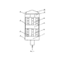
Схема глушителя шума выбросов пара представлена на фиг. 1.A diagram of a steam emission silencer is shown in Fig. 1.
Цифрами на фиг. 1 обозначены:The numbers in FIG. 1 are marked:
1 - корпус шумоглушителя;1 - silencer housing;
2 - дроссельные трубы;2 - throttling pipes;
3 - звукопоглощающий материал;3 - sound-absorbing material;
4 - отбойная пластина;4 - baffle plate;
5 - первый резонаторный блок;5 - the first resonator unit;
6 - первый дроссельный блок;6 - the first throttle unit;
7 - второй резонаторный блок;7 - the second resonator unit;
8 - второй дроссельный блок;8 - the second throttle unit;
9 - блок расширения;9 - expansion unit;
10 - крыша.10 - roof.
Глушитель шума выбросов пара устанавливается на выхлопном паропроводе, расположенном на крыше энергетического объекта. Выхлопные трубопроводы служат магистралями для сброса пара из предохранительных клапанов котельного агрегата в атмосферу.The silencer for noise emissions of steam is installed on the exhaust steam line located on the roof of the power facility. Exhaust pipelines serve as lines for the discharge of steam from the safety valves of the boiler unit to the atmosphere.
Глушитель шума выбросов пара работает следующим образом. В условиях применения, глушитель устанавливается на выхлопной паропровод предохранительно-сбросного клапана парового котла. Размеры устройства выполняются в зависимости от результатов математического моделирования с привязкой к реальному объекту - источнику шума. Пар, попадая из выхлопного трубопровода, расширяется в резонаторном блоке 5, а затем поступает в дроссельные трубы 2. Верхние концы труб первого дроссельного блока 6 заглушены, благодаря чему пар дросселируется, проходя через множество отверстий в трубах, при этом звуковая характеристика будет изменяться, т.к. общий уровень звуковой мощности парового выброса напрямую зависит от скорости выходной струи и площади сечения трубопровода. Затем через четыре отверстия, выполненные в верхнем несущем элементу первого дроссельного блока 6, пар поступает во второй резонаторный блок 7, где происходит гашение звуков низкой частоты. После резонатора пар поступает в основание второго дроссельного блока 8, в котором нижние концы дроссельных труб заглушены, а верхние концы труб имеют выход в блок расширения 9. Под действием давления пар через отверстия поступает в трубы, затем из которых направляется в выходную ступень, где происходит окончательное расширение и выброс пара в атмосферу.The muffler of noise emission of steam works as follows. Under the conditions of use, the muffler is installed on the exhaust steam line of the safety and relief valve of the steam boiler. The dimensions of the device are made depending on the results of mathematical modeling with reference to a real object - a noise source. Steam, entering from the exhaust pipe, expands in the resonator block 5, and then enters the
Такое устройство шумоглушителя позволит обеспечить снижение скоростей потоков пара, что повлечет за собой снижение звуковой мощности.Such a silencer device will allow reducing the steam flow rates, which will entail a decrease in the sound power.
Claims (1)
Priority Applications (1)
| Application Number | Priority Date | Filing Date | Title |
|---|---|---|---|
| RU2020101238U RU200098U1 (en) | 2020-01-10 | 2020-01-10 | STEAM EMISSION SILENCER |
Applications Claiming Priority (1)
| Application Number | Priority Date | Filing Date | Title |
|---|---|---|---|
| RU2020101238U RU200098U1 (en) | 2020-01-10 | 2020-01-10 | STEAM EMISSION SILENCER |
Publications (1)
| Publication Number | Publication Date |
|---|---|
| RU200098U1 true RU200098U1 (en) | 2020-10-06 |
Family
ID=72744373
Family Applications (1)
| Application Number | Title | Priority Date | Filing Date |
|---|---|---|---|
| RU2020101238U RU200098U1 (en) | 2020-01-10 | 2020-01-10 | STEAM EMISSION SILENCER |
Country Status (1)
| Country | Link |
|---|---|
| RU (1) | RU200098U1 (en) |
Cited By (1)
| Publication number | Priority date | Publication date | Assignee | Title |
|---|---|---|---|---|
| CN113912218A (en) * | 2021-11-09 | 2022-01-11 | 王廷伟 | Medical wastewater integrated treatment device |
Citations (4)
| Publication number | Priority date | Publication date | Assignee | Title |
|---|---|---|---|---|
| US6705428B2 (en) * | 2000-12-08 | 2004-03-16 | Abb Turbo Systems Ag | Exhaust gas system with helmholtz resonator |
| US8230967B2 (en) * | 2010-01-08 | 2012-07-31 | General Electric Company | Vane type silencers in elbow for gas turbine |
| RU2468217C2 (en) * | 2011-01-21 | 2012-11-27 | Закрытое акционерное общество "Концерн "Струйные технологии" | Resonant sound damper of reflecting type |
| RU2525993C1 (en) * | 2013-03-21 | 2014-08-20 | Открытое акционерное общество Научно-производственное объединение "Искра" | Exhaust unit for gas-turbine plant |
-
2020
- 2020-01-10 RU RU2020101238U patent/RU200098U1/en not_active IP Right Cessation
Patent Citations (4)
| Publication number | Priority date | Publication date | Assignee | Title |
|---|---|---|---|---|
| US6705428B2 (en) * | 2000-12-08 | 2004-03-16 | Abb Turbo Systems Ag | Exhaust gas system with helmholtz resonator |
| US8230967B2 (en) * | 2010-01-08 | 2012-07-31 | General Electric Company | Vane type silencers in elbow for gas turbine |
| RU2468217C2 (en) * | 2011-01-21 | 2012-11-27 | Закрытое акционерное общество "Концерн "Струйные технологии" | Resonant sound damper of reflecting type |
| RU2525993C1 (en) * | 2013-03-21 | 2014-08-20 | Открытое акционерное общество Научно-производственное объединение "Искра" | Exhaust unit for gas-turbine plant |
Cited By (1)
| Publication number | Priority date | Publication date | Assignee | Title |
|---|---|---|---|---|
| CN113912218A (en) * | 2021-11-09 | 2022-01-11 | 王廷伟 | Medical wastewater integrated treatment device |
Similar Documents
| Publication | Publication Date | Title |
|---|---|---|
| DK0934457T4 (en) | Gas flow damper | |
| US20220026059A1 (en) | Pulsating combustion device with improved energy conversion efficiency and reduced noise level | |
| BRPI0709808B1 (en) | muffler to attenuate noise | |
| KR101091938B1 (en) | Muffler for Engine Waste Gas with Reduction Means for Jet Noise | |
| CN214500335U (en) | Pipeline with noise elimination structure | |
| EP0723123B1 (en) | Sound-damped combustion system, and damper for such a system | |
| EP3850197B1 (en) | An exhaust gas assembly | |
| JP6579924B2 (en) | Chimney noise reduction system and setting method of chimney noise reduction system | |
| RU19555U1 (en) | NOISE MUFFLER | |
| Floyd | Control of steam venting noise in power plants | |
| RU2310762C2 (en) | Gas flow conical noise silencer | |
| JP2005220871A (en) | Silencer | |
| RU22227U1 (en) | MUFFLER MUFFLER | |
| GB2577320A (en) | Rotating air flow duct silencer | |
| RU163468U1 (en) | SMOKE PIPE OF A HEATING BOILER OPERATING ON GAS FUEL | |
| RU2586804C1 (en) | Exhaust steam jet silencer (versions) | |
| RU2210699C2 (en) | Hot-water boiler | |
| Semin et al. | Noise reduction from combined-cycle plants subject to their configuration | |
| RU2310761C2 (en) | Variable section noise silencer | |
| CN116025596A (en) | A sound-absorbing interference type muffler | |
| Yadav et al. | Noise Reduction Techniques for Forced Draft Fan in Thermal Power Plant using Absorptive Silencer | |
| RU2184900C2 (en) | Silencer | |
| Weirich | Power plant noise attenuation: Gas turbines and valves | |
| WO2022152034A1 (en) | Pipeline provided with silencing structure | |
| WO2021154108A1 (en) | Gaseous medium nonreturn valve for pulsating combustion device |
Legal Events
| Date | Code | Title | Description |
|---|---|---|---|
| MM9K | Utility model has become invalid (non-payment of fees) |
Effective date: 20200823 |