RU2009309C1 - Hydromechanical anchor - Google Patents
Hydromechanical anchor Download PDFInfo
- Publication number
- RU2009309C1 RU2009309C1 SU4909050A RU2009309C1 RU 2009309 C1 RU2009309 C1 RU 2009309C1 SU 4909050 A SU4909050 A SU 4909050A RU 2009309 C1 RU2009309 C1 RU 2009309C1
- Authority
- RU
- Russia
- Prior art keywords
- rod
- support
- protrusion
- anchor
- housing
- Prior art date
Links
- 230000002028 premature Effects 0.000 claims abstract description 5
- 230000003993 interaction Effects 0.000 claims abstract description 4
- 230000000694 effects Effects 0.000 abstract description 2
- 230000021615 conjugation Effects 0.000 abstract 1
- 230000008030 elimination Effects 0.000 abstract 1
- 238000003379 elimination reaction Methods 0.000 abstract 1
- 239000000126 substance Substances 0.000 abstract 1
- 230000008878 coupling Effects 0.000 description 2
- 238000010168 coupling process Methods 0.000 description 2
- 238000005859 coupling reaction Methods 0.000 description 2
- 238000007789 sealing Methods 0.000 description 2
- 238000004873 anchoring Methods 0.000 description 1
- 230000005540 biological transmission Effects 0.000 description 1
- 238000010835 comparative analysis Methods 0.000 description 1
- 238000000605 extraction Methods 0.000 description 1
- 239000007788 liquid Substances 0.000 description 1
Images
Landscapes
- Piles And Underground Anchors (AREA)
Abstract
Description
Изобретение относится к нефтегазодобывающей промышленности, а именно к устройствам для зацепления со стенками скважины и удержания колонны труб с пакером от осевого перемещения. The invention relates to the oil and gas industry, and in particular to devices for engaging with the walls of the well and holding the pipe string with the packer from axial movement.
Известен пакер, совмещенный с якорями типа ЗПД-ЯГ (пакеры, якори, разъединители колонн, инструменты и принадлежности для них). Якорь состоит из верхнего и нижнего заякоривающих устройств, уплотнительных манжет, размещенных между ними гидроцилиндров, срезных фиксирующих винтов и жестко связанных между собой штоков. Устройство рассчитано для проведения одной операции и не обеспечивает многократной работы [1] . Known packer, combined with anchors of the type ZPD-YAG (packers, anchors, column disconnectors, tools and accessories for them). An anchor consists of upper and lower anchoring devices, sealing cuffs, hydraulic cylinders placed between them, shear fixing screws and rods rigidly connected to each other. The device is designed for one operation and does not provide multiple work [1].
Известно также устройство для закрытия скважины, состоящее из пакера, якоря, хвостовика и корпуса с уплотнительными элементами. Отцепление плашек якоря от стенки скважины осуществляется за счет усилия пружины [2] . A well closure device is also known, consisting of a packer, an anchor, a liner and a housing with sealing elements. The anchor dies are disconnected from the well wall due to the spring force [2].
Применение пружин, рассчитанных на большие усилия в скважинном оборудовании, имеющего ограниченные размеры, практически невозможно и нецелесообразно. Изобретение позволяет повысить надежность работы якоря за счет устранения преждевременной посадки и облегчения его извлечения. The use of springs, designed for great efforts in downhole equipment, having limited dimensions, is practically impossible and inexpedient. The invention improves the reliability of the anchor by eliminating premature landing and facilitate its extraction.
Достигается это тем, что, якорь гидромеханический снабжен жестко связанным с опорой патрубка хвостовиком, который размещен в кольцевой полости между штоком и корпусом и связан шлицевым соединением со штоком, а патрубок установлен с возможностью сопряжения наружным торцом его опоры с внутренним выступом корпуса, и взаимодействия нижним торцом опоры с наружным выступом штока, при этом расстояние от верхней конической части конуса до верхнего торца плашек меньше расстояния между выступом штока и нижним торцом опоры патрубка, а последнее меньше расстояния между уступом переводника и верхним торцом внутреннего выступа корпуса. This is achieved by the fact that the hydromechanical anchor is equipped with a shank rigidly connected to the support of the nozzle, which is located in the annular cavity between the stem and the housing and is connected by a spline connection with the stem, and the nozzle is installed with the possibility of coupling the external end of its support with the internal protrusion of the housing, and the lower interaction the butt end of the support with the outer protrusion of the rod, while the distance from the upper conical part of the cone to the upper end of the dies is less than the distance between the rod protrusion and the lower end of the nozzle support, and the last m less distance between the ledge of the sub and the upper end of the inner ledge of the housing.
Сопоставительный анализ с прототипом показывает, что перевод якоря из рабочего в транспортное положение осуществляется принудительно созданием растягивающей нагрузки на колонну труб, что достигается путем применения новых конструктивных элементов. Comparative analysis with the prototype shows that the transfer of the anchor from the worker to the transport position is carried out by force by creating a tensile load on the pipe string, which is achieved by using new structural elements.
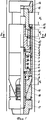
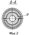
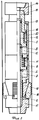
На фиг. 1 изображен продольный разрез якоря гидромеханического при спуско-подъемных операциях; на фиг. 2 - поперечный разрез по сечению А-А на фиг. 1; на фиг. 3 - продольный разрез якоря гидромеханического после установки его в скважине. In FIG. 1 shows a longitudinal section of a hydromechanical anchor during tripping; in FIG. 2 is a cross-sectional view taken along section AA in FIG. 1; in FIG. 3 - a longitudinal section of the hydromechanical anchor after installing it in the well.
Якорь гидромеханический включает жестко связанные между собой полые штоки 1 и 2 с поршнями 3 и 4, телескопически установленные относительно штоков жестко связанные между собой корпусные детали 5 и 6 с выступами 7 и 8. Между корпусными деталями с выступами и штоками с поршнями образованы камеры 9 и 10, сообщенные через радиальные каналы А и Б с полостью штоков. Для удержания корпусных деталей в верхнем положении относительно штоков в кольцевой полости над поршнем 4 установлена пружина 11. В верхнем штоке 1 предусмотрен наружный выступ 12, а в верхнем корпусе 5 - внутренний выступ 13. В верхней части якоря имеется переводник с выступом 14, который жестко связан патрубком 15 с опорой 16. К нижнему концу штока 2 жестко закреплен переводник 17, в Т-образном выборе которого установлены с возможностью радиального перемещения плашки 18, к выступу 8 корпуса 6 закреплен конус 19. Плашки 18 находятся в зацеплении с конусом 19 при помощи соответствующих пазов в виде ласточкиного хвоста. The hydromechanical anchor includes
Опора 16 патрубка 15 снабжена жестко связанным с ней хвостовиком 20, размещенным в кольцевой полости между штоком 1 и корпусом 5 и связанным шлицевым соединением 21 со штоком 1. Патрубок 15 установлен с возможностью сопряжения наружным торцом его опоры 16 с внутренним выступом 13 корпуса 5 и взаимодействия нижним торцом его опоры 16 с наружным выступом 12 штока 1. При этом расстояние от верхней конической части конуса 19 до верхнего торца плашек 18 меньше расстояния между наружным выступом 12 штока 1 и нижним торцом опоры 16 патрубка 15, а последнее - меньше расстояния между уступом переводника 14 и верхним торцом внутреннего выступа 13 корпуса 5, т. е. Н1 < Н2 < Н3.The
Перед спуском якорь устанавливают над пакером (не показан). При спуске якоря в скважину плашки 18 находятся в сложенном состоянии, как показано на фиг. 1. Before the descent, the anchor is installed above the packer (not shown). When the anchors are lowered into the well, the
В случае преждевременной посадки якоря в скважине, патрубок 15 с хвостовиком 20 перемещается вниз до упора нижнего торца опоры 16 с наружным выступом 12 штока 1. Но поскольку Н3 > Н2 > Н1, то между торцом переводника с уступом 14 и верхним торцом внутреннего выступа 13 корпуса 5 остается зазор. В результате переводник с выступом 14 не доходит до упора с внутренним выступом 13 корпуса 5. Поэтому при посадке якоря осевая сжимающая нагрузка на корпусные детали 5 и 6, следовательно, и на конус 19 не передается, и в результате предотвращается преждевременное перемещение плашек 18 в радиальном направлении и зацепление их со стенками скважины.In the case of premature landing of the anchor in the well, the
Для установки якоря в скважине колонны труб разгружают и внутри труб создают избыточное давление. Под действием избыточного давления внутритрубная жидкость через каналы А и Б поступает в камеры 9 и 10 и воздействует на площади поперечного сечения выступов 7 и 8 и поршней 3 и 4. В результате корпусные детали 5 и 6 и конус 19 перемещают вниз относительно штоков 1 и 2, сжимая пружину 11. Конус 19 раздвигает плашки 18 до контакта со стенками скважины или колонны труб и расклинивает их в неподвижном положении, как представлено на фиг. 3. To install the anchor in the well, the pipe string is unloaded and excess pressure is created inside the pipe. Under the action of excessive pressure, the in-tube liquid through the channels A and B enters the
При проведении технологических операций, например, гидравлическом разрыве под действием создаваемого внутритрубного давления пакер, размещенный под якорем, стремится перемещаться вверх. Однако, чем больше величина избыточного давления внутри труб, тем больше величина усилия, действующего на конус 19, следовательно, тем больше усилие сцепления плашек 18 со стенками колонны или скважины. В результате исключается возможность вертикального перемещения пакера вверх, жестко связанного через переводник 17 с плашками 18. When carrying out technological operations, for example, a hydraulic fracture under the influence of the generated in-pipe pressure, the packer, placed under the anchor, tends to move up. However, the greater the magnitude of the overpressure inside the pipes, the greater the magnitude of the force acting on the
Для перевода якоря из рабочего в транспортное положение давление внутри труб снимают и инструмент приподнимают. При этом опора 16 патрубка 15 наружным торцом упирается с внутренним выступом 13 корпуса 5, конус 19 под действием растягивающей нагрузки перемещается вверх относительно плашек 18. Последние и пружина 11 принимают исходное положение, как показано на фиг. 1. To transfer the anchor from the worker to the transport position, the pressure inside the pipes is removed and the tool is raised. In this case, the
Передача крутящего момента от патрубка 15 на нижнюю часть якоря осуществляется шлицевым соединением 21. The transmission of torque from the
Увеличение усилия сцепления на стенку скважины в предлагаемом якоре достигается введением дополнительной камеры, в данном примере введением камеры 10. Количество таких камер может быть практически несколько. The increase in the adhesion force to the wall of the well in the proposed anchor is achieved by the introduction of an additional chamber, in this example, the introduction of the
Экономический эффект от предлагаемого якоря достигается за счет повышения надежности работы якоря путем уменьшения количества неудачных операций при освоении и эксплуатации скважин. (56) Пакеры, якори, разъединители колонн, инструменты и принадлежности для них. Каталог ЦИНТИХИМНефтемаш. - М. : 1984, с. 13. The economic effect of the proposed anchor is achieved by increasing the reliability of the anchor by reducing the number of unsuccessful operations during the development and operation of wells. (56) Packers, anchors, column disconnectors, tools and accessories for them. Catalog TSINTIKHIMNeftemash. - M.: 1984, p. thirteen.
Авторское свидетельство СССР N 250806, кл. E 21 B 33/12, 1968. USSR copyright certificate N 250806, cl. E 21 B 33/12, 1968.
Claims (1)
Priority Applications (1)
| Application Number | Priority Date | Filing Date | Title |
|---|---|---|---|
| SU4909050 RU2009309C1 (en) | 1991-02-07 | 1991-02-07 | Hydromechanical anchor |
Applications Claiming Priority (1)
| Application Number | Priority Date | Filing Date | Title |
|---|---|---|---|
| SU4909050 RU2009309C1 (en) | 1991-02-07 | 1991-02-07 | Hydromechanical anchor |
Publications (1)
| Publication Number | Publication Date |
|---|---|
| RU2009309C1 true RU2009309C1 (en) | 1994-03-15 |
Family
ID=21559325
Family Applications (1)
| Application Number | Title | Priority Date | Filing Date |
|---|---|---|---|
| SU4909050 RU2009309C1 (en) | 1991-02-07 | 1991-02-07 | Hydromechanical anchor |
Country Status (1)
| Country | Link |
|---|---|
| RU (1) | RU2009309C1 (en) |
Cited By (15)
| Publication number | Priority date | Publication date | Assignee | Title |
|---|---|---|---|---|
| RU2140518C1 (en) * | 1998-02-04 | 1999-10-27 | Францев Владимир Федорович | Packer lock |
| RU2144127C1 (en) * | 1998-04-13 | 2000-01-10 | Кузаев Григорий Иванович | Gear fixing deep pumping equipment in well |
| RU2169829C1 (en) * | 1999-11-16 | 2001-06-27 | Открытое акционерное общество Научно-производственное объединение Роснефть-Термнефть | Multipurpose in-well valve-shut-off device |
| RU2205939C2 (en) * | 1999-11-04 | 2003-06-10 | Общество с ограниченной ответственностью фирма "Саратовгазприборавтоматика" | Tool for packer seating |
| RU2220274C1 (en) * | 2002-04-24 | 2003-12-27 | Открытое акционерное общество "Татнефть" им. В.Д. Шашина | Hydraulic anchor |
| RU2229013C2 (en) * | 2000-08-04 | 2004-05-20 | Общество с ограниченной ответственностью "Кубаньгазпром" | Method for operating tubing pipes in gas well and device for realization of said method |
| RU2265713C2 (en) * | 2003-08-04 | 2005-12-10 | Общество с ограниченной ответственностью "Кубаньгазпром" (ООО "Кубаньгазпром") | Device for tubing string operation into gas well |
| RU2293838C2 (en) * | 2004-12-14 | 2007-02-20 | Рамиль Владимирович Степанов | Casing column cementation method and device for realization thereof |
| RU2299309C2 (en) * | 2005-03-09 | 2007-05-20 | Рамиль Владимирович Степанов | Cementing device and method for casing pipe with two cementing plugs |
| RU2397307C1 (en) * | 2009-06-26 | 2010-08-20 | Открытое акционерное общество "Татнефть" им. В.Д. Шашина | Hydro-mechanical anchor |
| RU2477781C1 (en) * | 2011-10-07 | 2013-03-20 | Общество с ограниченной ответственностью Научно-производственная фирма "Пакер" | Hydraulic anchor |
| RU2634318C1 (en) * | 2016-09-15 | 2017-10-25 | Общество с ограниченной ответственностью Научно-производственная фирма "Пакер" | Self-retaining hydraulic armature |
| CN108952665A (en) * | 2018-09-14 | 2018-12-07 | 广州海洋地质调查局 | A kind of hydraulic slotted liner technique device of semisubmersible drilling platform or drill ship |
| CN110439489A (en) * | 2019-09-18 | 2019-11-12 | 东营市元捷石油机械有限公司 | Fill the water anti-jack slips anchor |
| CN114875847A (en) * | 2022-05-06 | 2022-08-09 | 江西中一建工集团有限公司 | Be used for water conservancy building side slope support device |
-
1991
- 1991-02-07 RU SU4909050 patent/RU2009309C1/en active
Cited By (17)
| Publication number | Priority date | Publication date | Assignee | Title |
|---|---|---|---|---|
| RU2140518C1 (en) * | 1998-02-04 | 1999-10-27 | Францев Владимир Федорович | Packer lock |
| RU2144127C1 (en) * | 1998-04-13 | 2000-01-10 | Кузаев Григорий Иванович | Gear fixing deep pumping equipment in well |
| RU2205939C2 (en) * | 1999-11-04 | 2003-06-10 | Общество с ограниченной ответственностью фирма "Саратовгазприборавтоматика" | Tool for packer seating |
| RU2169829C1 (en) * | 1999-11-16 | 2001-06-27 | Открытое акционерное общество Научно-производственное объединение Роснефть-Термнефть | Multipurpose in-well valve-shut-off device |
| RU2229013C2 (en) * | 2000-08-04 | 2004-05-20 | Общество с ограниченной ответственностью "Кубаньгазпром" | Method for operating tubing pipes in gas well and device for realization of said method |
| RU2220274C1 (en) * | 2002-04-24 | 2003-12-27 | Открытое акционерное общество "Татнефть" им. В.Д. Шашина | Hydraulic anchor |
| RU2265713C2 (en) * | 2003-08-04 | 2005-12-10 | Общество с ограниченной ответственностью "Кубаньгазпром" (ООО "Кубаньгазпром") | Device for tubing string operation into gas well |
| RU2293838C2 (en) * | 2004-12-14 | 2007-02-20 | Рамиль Владимирович Степанов | Casing column cementation method and device for realization thereof |
| RU2299309C2 (en) * | 2005-03-09 | 2007-05-20 | Рамиль Владимирович Степанов | Cementing device and method for casing pipe with two cementing plugs |
| RU2397307C1 (en) * | 2009-06-26 | 2010-08-20 | Открытое акционерное общество "Татнефть" им. В.Д. Шашина | Hydro-mechanical anchor |
| RU2477781C1 (en) * | 2011-10-07 | 2013-03-20 | Общество с ограниченной ответственностью Научно-производственная фирма "Пакер" | Hydraulic anchor |
| RU2634318C1 (en) * | 2016-09-15 | 2017-10-25 | Общество с ограниченной ответственностью Научно-производственная фирма "Пакер" | Self-retaining hydraulic armature |
| CN108952665A (en) * | 2018-09-14 | 2018-12-07 | 广州海洋地质调查局 | A kind of hydraulic slotted liner technique device of semisubmersible drilling platform or drill ship |
| CN108952665B (en) * | 2018-09-14 | 2024-05-10 | 广州海洋地质调查局 | Hydraulic slotting device of semi-submersible drilling platform or drilling ship |
| CN110439489A (en) * | 2019-09-18 | 2019-11-12 | 东营市元捷石油机械有限公司 | Fill the water anti-jack slips anchor |
| CN114875847A (en) * | 2022-05-06 | 2022-08-09 | 江西中一建工集团有限公司 | Be used for water conservancy building side slope support device |
| CN114875847B (en) * | 2022-05-06 | 2023-04-25 | 江西中一建工集团有限公司 | Be used for hydraulic building side slope strutting arrangement |
Similar Documents
| Publication | Publication Date | Title |
|---|---|---|
| RU2009309C1 (en) | Hydromechanical anchor | |
| US3358760A (en) | Method and apparatus for lining wells | |
| US4834175A (en) | Hydraulic versa-trieve packer | |
| US4930573A (en) | Dual hydraulic set packer | |
| RU2100568C1 (en) | Device for oil and gas wells applicable in their sealing (versions) | |
| US3776307A (en) | Apparatus for setting a large bore packer in a well | |
| US20020121380A1 (en) | Collet-cone slip system for releasably securing well tools | |
| EP2501895B1 (en) | Method and system for lining a section of a wellbore with an expandable tubular element | |
| GB2175330A (en) | Tubular member anchoring arrangement and method | |
| WO1979001087A1 (en) | Fluid pressure set and released well packer apparatus | |
| US4624483A (en) | Quick connect coupler | |
| US3374838A (en) | Fluid expansible packer and anchor apparatus | |
| US3029872A (en) | Telescopic bridging plug-pressure set | |
| RU2137901C1 (en) | Packer | |
| CA2119504A1 (en) | Apparatus for releasing perforating gun equipment from a well casing | |
| US3062292A (en) | Well packer | |
| RU2120023C1 (en) | Packer | |
| RU2674781C1 (en) | Liner packer hanger, hydraulic drive of anchor liner packer hanger, piston of liner packer hanger, hydraulic drive assembly of liner packer hanger | |
| US3235017A (en) | Earth borehole drilling and testing tool | |
| US4565247A (en) | Wireline set tubing retrievable seal bore packer apparatus | |
| RU2236556C1 (en) | Drillable mechanical packer | |
| RU2101461C1 (en) | Packer | |
| RU2018628C1 (en) | Hydraulic packer of multiple use | |
| US6267180B1 (en) | Packer releasing tool and method for releasing a packer assembly from a wellbore | |
| US5335729A (en) | Tubular connection, method for making same, and tool therefor |