RU2011103C1 - Device for connecting hoses - Google Patents
Device for connecting hoses Download PDFInfo
- Publication number
- RU2011103C1 RU2011103C1 SU4912239A RU2011103C1 RU 2011103 C1 RU2011103 C1 RU 2011103C1 SU 4912239 A SU4912239 A SU 4912239A RU 2011103 C1 RU2011103 C1 RU 2011103C1
- Authority
- RU
- Russia
- Prior art keywords
- housing
- flats
- fitting
- locking element
- pipe union
- Prior art date
Links
- 238000007789 sealing Methods 0.000 claims abstract description 14
- 238000004519 manufacturing process Methods 0.000 abstract description 2
- 239000011324 bead Substances 0.000 abstract 2
- 239000000126 substance Substances 0.000 abstract 1
- 238000010276 construction Methods 0.000 description 1
- 210000004209 hair Anatomy 0.000 description 1
- 238000011089 mechanical engineering Methods 0.000 description 1
- 238000005065 mining Methods 0.000 description 1
- 230000002269 spontaneous effect Effects 0.000 description 1
Images

Landscapes
- Joints Allowing Movement (AREA)
Abstract
Description
Изобретение относится к машиностроению и предназначено для присоединения и отсоединения потребителя сжатого воздуха от пневмосети, находящейся под давлением, и может быть использовано в горной и строительной технике, например, при присоединении пневмопробойника к пневмосети. The invention relates to mechanical engineering and is intended for connecting and disconnecting a consumer of compressed air from a pneumatic network under pressure, and can be used in mining and construction equipment, for example, when connecting a pneumatic punch to a pneumatic network.
Известно устройство для соединения рукавов, содержащее корпус с окном и упругим уплотнительным элементом, штуцер с буртом, запорный элемент со сквозным отверстием для штуцера, установленного с возможностью поворота. Уплотнительный и запорный элементы выполнены со сферической поверхностью, причем диаметр этих сферических поверхностей выполнен больше, чем окно в корпусе. A device for connecting hoses is known, comprising a housing with a window and an elastic sealing element, a fitting with a shoulder, a locking element with a through hole for the fitting mounted for rotation. The sealing and locking elements are made with a spherical surface, and the diameter of these spherical surfaces is made larger than the window in the housing.
Недостатками известного технического решения являются: а) невозможность передачи крутящего момента; б) сложность выполнения сферических поверхностей. Первое исключает применение устройства в пневмопробойниках с поворотным реверсом. Второе резко удорожает производство и не обеспечивает герметизацию через контактирующие поверхности. The disadvantages of the known technical solutions are: a) the impossibility of transmitting torque; b) the complexity of performing spherical surfaces. The first eliminates the use of the device in pneumatic punch with rotary reverse. The second dramatically increases the cost of production and does not provide sealing through contact surfaces.
Задача изобретения состоит в повышении эффективности работы путем обеспечения возможности передачи крутящего момента при одновременном упрощении конструкции. The objective of the invention is to increase the efficiency by providing the possibility of transmitting torque while simplifying the design.
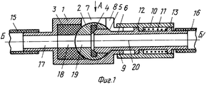
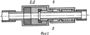
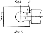
На фиг. 1 изображено устройство, общий вид в продольном сечении; на фиг. 2 - продольное сечение I-I на фиг. 1; на фиг. 3 - вид по стрелке А на фиг. 1; на фиг. 4 - сечение II-II на фиг. 2 при выполнении лысок асимметричными; на фиг. 5 - при выполнении дополнительных лысок и все лыски выполнены симметричными. In FIG. 1 shows a device, a General view in longitudinal section; in FIG. 2 is a longitudinal section I-I in FIG. 1; in FIG. 3 is a view along arrow A in FIG. 1; in FIG. 4 is a section II-II in FIG. 2 when performing the flats asymmetric; in FIG. 5 - when performing additional flats and all flats are symmetrical.
Устройство для соединения рукавов состоит из корпуса 1, запорного элемента 2 в виде цилиндра, уплотнительных элементов 3, 4, штуцера 5 с лысками 6. В корпусе 1 выполнены окно 7 и паз 8 и на боковой поверхности он выполнен с кольцевым выступом 9. На штуцере 5 размещена подвижная втулка 10 с пружиной 11, имеются кольцевые бурты 12, 13 и лыски 6, которые могут быть выполненными симметричными или асимметричными относительно продольной оси. Штуцер 5 может быть выполнен с дополнительными лысками 14 (см. фиг. 5), смещенными по окружности относительно основных лысок на 90о. Рукава обозначены позициями 15, 16, а каналы корпуса, уплотнения запорного элемента и штуцера соответственно - 17, 18, 19, 20.The device for connecting the sleeves consists of a housing 1, a locking element 2 in the form of a cylinder, sealing elements 3, 4, a fitting 5 with
Принцип работы устройства для соединения рукавов. При разомкнутых рукавах 15, 16 запорный элемент 2 установлен таким образом, что канал 19 запорного элемента 2 установлен перпендикулярно каналам 17, 18 корпуса 1 и уплотнительного элемента 3. Стенкой уплотнительного элемента 3 происходит перекрытие сжатого воздуха, находящегося в рукаве 15. The principle of operation of the device for connecting the sleeves. When the
Для соединения рукавов 15, 16 необходимо штуцер 5 передним торцем разместить через окно 7 корпуса 1 в отверстие запорного элемента 2. При этом сжимается уплотнительное кольцо 4, что герметизирует стык между торцами штуцера 15 и запорным элементом 2. Затем, отжимая втулку 10 проворачивают штуцер 5 совместно с запорным элементом 2 в корпусе 1. Лыски 6 штуцера 5 проходят в пазу 8 корпуса 1 и штуцер 5 поворачивается до упора в корпус 1. Отпускается втулка 10 и под действием пружины 11 она своим передним торцем входит в кольцевой выступ 9 корпуса 1, что фиксирует положение, показанное на фиг. 1. В этом положении все каналы 17-20 соответственно корпуса 1, уплотнительного элемента 3, запорного элемента 2 и штуцера 5 располагаются вдоль одной оси и сжатый воздух из рукава 15 поступит в рукав 16. Уплотнительные элементы 3 и 4, выбрав зазоры между контактирующими элементами, исключат утечку сжатого воздуха. Пружина 11 будет удерживать втулку 10 в переднем положении (левом на фиг. 1), исключая возможность самопроизвольного рассоединения. To connect the
Расположение торцев цилиндра параллельно вращению штуцера позволяет передавать вращательный момент от одного рукава другому, т. к. цилиндрическая поверхность, размещенная между поперечной осью и торцами исключает поворот запорного элемента относительно корпуса. The arrangement of the ends of the cylinder parallel to the rotation of the fitting allows you to transfer torque from one sleeve to another, because a cylindrical surface located between the transverse axis and the ends prevents rotation of the locking element relative to the housing.
Для рассоединения рукавов 15 и 16 необходимо вышеописанные операции повторить в обратной последовательности, т. е. отодвинуть втулку 10 от кольцевого выступа 9 корпуса 1, затем развернуть штуцер 5 вместе с запорным элементом 2 на 90о и вытащить штуцер 5 из запорного элемента 2. При этом стенки запорного элемента 2 перекроют канал 17.To disconnect the
При выполнении лысок 6 симметричными относительно продольной оси устройства упрощается сборка соединения, т. к. любой взятый штуцер 2 будет состыковываться с пазом 8 корпуса 1. When performing
При выполнении дополнительных лысок 14, смещенных относительно основных 6 по окружности, при соединении элементов устройства можно проворачивать штуцер 5 в двух положениях, размещенных друг относительно друга на 90о. При износе одних лысок, например, 6, можно будет использовать другую пару - 14. (56) Авторское свидетельство СССР N 1539441, кл. F 16 L 37/24, 1988.When performing
Claims (4)
Priority Applications (1)
| Application Number | Priority Date | Filing Date | Title |
|---|---|---|---|
| SU4912239 RU2011103C1 (en) | 1991-01-03 | 1991-01-03 | Device for connecting hoses |
Applications Claiming Priority (1)
| Application Number | Priority Date | Filing Date | Title |
|---|---|---|---|
| SU4912239 RU2011103C1 (en) | 1991-01-03 | 1991-01-03 | Device for connecting hoses |
Publications (1)
| Publication Number | Publication Date |
|---|---|
| RU2011103C1 true RU2011103C1 (en) | 1994-04-15 |
Family
ID=21561052
Family Applications (1)
| Application Number | Title | Priority Date | Filing Date |
|---|---|---|---|
| SU4912239 RU2011103C1 (en) | 1991-01-03 | 1991-01-03 | Device for connecting hoses |
Country Status (1)
| Country | Link |
|---|---|
| RU (1) | RU2011103C1 (en) |
-
1991
- 1991-01-03 RU SU4912239 patent/RU2011103C1/en active
Similar Documents
| Publication | Publication Date | Title |
|---|---|---|
| US3930674A (en) | Couplings | |
| US4927192A (en) | Pipe connector load element | |
| US4159132A (en) | Sealed connection | |
| US2412394A (en) | Pipe coupling | |
| US1905324A (en) | Pipe coupling | |
| US1924020A (en) | Tight joint for pipings | |
| US4068864A (en) | Single element flexible connection | |
| EP0664865B1 (en) | Pipe end coupling with circumferentially movable clamping jaws | |
| US4529211A (en) | Pipe joint and seal | |
| US2777714A (en) | Clamp-lock swivel elbow | |
| US4938509A (en) | Multiple port fluid coupler | |
| US3107931A (en) | Pipe expansion joint | |
| RU2094687C1 (en) | Pipe joint | |
| US3307862A (en) | Quick-disconnect fluid conduit connection | |
| RU2062939C1 (en) | Quick-detachable pipe joint | |
| US3563576A (en) | Tubular joint contruction | |
| US4116473A (en) | Pipe coupling | |
| US4807913A (en) | Heat blocking junction | |
| CN117980649A (en) | Two-phase connector | |
| SU631739A1 (en) | Permanent connection of high pressure reinforced hoses | |
| US1545221A (en) | Pipe and other joint and the like | |
| KR20210098646A (en) | Connector for specific piping connections | |
| GB2131112A (en) | Rotary joint | |
| SU1492165A1 (en) | Disconnectable pipeline joint | |
| SU775498A1 (en) | Quick-release joint of pipelines |