RU2012181C1 - Method for application of mineral fertilizer mixtures - Google Patents
Method for application of mineral fertilizer mixtures Download PDFInfo
- Publication number
- RU2012181C1 RU2012181C1 SU4839719A RU2012181C1 RU 2012181 C1 RU2012181 C1 RU 2012181C1 SU 4839719 A SU4839719 A SU 4839719A RU 2012181 C1 RU2012181 C1 RU 2012181C1
- Authority
- RU
- Russia
- Prior art keywords
- zones
- fertilizers
- flows
- radius
- feed
- Prior art date
Links
- 239000003337 fertilizer Substances 0.000 title claims abstract description 23
- 239000000203 mixture Substances 0.000 title claims description 13
- 238000000034 method Methods 0.000 title claims description 10
- 229910052500 inorganic mineral Inorganic materials 0.000 title claims description 7
- 239000011707 mineral Substances 0.000 title claims description 7
- 238000007873 sieving Methods 0.000 claims description 5
- 239000013598 vector Substances 0.000 claims description 3
- 239000000126 substance Substances 0.000 abstract 1
- 239000002245 particle Substances 0.000 description 4
- 238000010586 diagram Methods 0.000 description 2
- 238000009434 installation Methods 0.000 description 2
- 238000000926 separation method Methods 0.000 description 1
Images
Landscapes
- Fertilizing (AREA)
- Fertilizers (AREA)
Abstract
Description
Изобретение относится к сельскому хозяйству, а именно к технологии внесения минеральных удобрений и их смесей. The invention relates to agriculture, namely to the technology of making mineral fertilizers and their mixtures.
Известен способ внесения смесей минеральных удобрений, заключающийся в подаче их на конический горизонтально расположенный рабочий орган, перемещении вдоль лопаток и по поверхности конуса между лопатками и распределении по полю поверхностью конуса и нижними краями лопаток [1] . A known method of introducing mixtures of mineral fertilizers, which consists in feeding them to a conical horizontally located working body, moving along the blades and along the surface of the cone between the blades and distributing the cone surface and the lower edges of the blades across the field [1].
Недостатком этого способа является то, что расслоение смесей при их транспортировке, хранении, перегрузке приводит к повышению неравномерности распределения удобрений по поверхности поля, а внесение удобрений предварительно несмешанных данный способ не предусматривает. The disadvantage of this method is that the separation of the mixtures during their transportation, storage, transshipment leads to an increase in the uneven distribution of fertilizers on the surface of the field, and the introduction of fertilizers previously unmixed this method does not provide.
Наиболее близким к предлагаемому является способ внесения, заключающийся в подаче удобрений на центробежный диск в виде отдельных потоков, причем каждый поток подает в свою зону со смещением по радиусу диска [2] . Closest to the proposed is the application method, which consists in feeding fertilizers to the centrifugal disc in the form of separate streams, with each stream feeding into its zone with an offset along the radius of the disk [2].
Недостатком данного способа является то, что он не предусматривает изменения положения зон подачи каждого потока относительно среднего радиуса подачи. Поэтому этим способом нельзя вносить несмешанные удобрения, так как при изменении сочетания удобрений (коэффициентов трения) произойдет смещение секторов рассева каждого удобрения, а в результате и увеличение неравномерности внесения смеси. The disadvantage of this method is that it does not provide for a change in the position of the feed zones of each stream relative to the average feed radius. Therefore, this method cannot be applied unmixed fertilizers, since when changing the combination of fertilizers (friction coefficients), the sieving sectors of each fertilizer will shift, and as a result, the unevenness of the mixture will increase.
Целью изобретения является повышение равномерности смешивания и рассева минеральных удобрений. The aim of the invention is to increase the uniformity of mixing and sieving of mineral fertilizers.
Достигается это тем, что в данном способе внесения смесей минеральных удобрений координаты зон подачи отдельных потоков определяют по формулам:
rA,Б= ![]()
Δλn= arcsin![]()
![]()
е - эксцентриситет центров этих зон,
Δλn - отклонение в углах подачи потоков,
Ro - средний радиус подачи потоков,
β - угол поворота зоны подачи относительно радиуса диска, который изменяют так, чтобы выполнялось условие:
Δλn - Δω t - Δθ = 0, где Δω t - отклонение в углах схода потоков с диска;
Δθ - отклонение в углах между радиус-векторами скоростей схода потоков.This is achieved by the fact that in this method of applying mixtures of mineral fertilizers, the coordinates of the feed zones of individual flows are determined by the formulas:
r A, B = ![]()
Δλ n = arcsin ![]()
![]()
e is the eccentricity of the centers of these zones,
Δλ n - deviation in the corners of the flow flows,
R o - the average radius of the flow,
β is the angle of rotation of the feed zone relative to the radius of the disk, which is changed so that the condition:
Δλ n - Δω t - Δθ = 0, where Δω t is the deviation in the angles of descent of flows from the disk;
Δθ is the deviation in the angles between the radius vectors of the velocities of the flows.
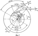
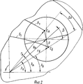
На фиг. 1 дана схема распределения удобрений, предварительно несмешанных; на фиг. 2 - схема зоны подачи этих удобрений. In FIG. 1 shows a distribution diagram of fertilizers previously unmixed; in FIG. 2 is a diagram of the feed zone of these fertilizers.
Способ внесения смесей минеральных удобрений осуществляется следующим образом. The method of applying mixtures of mineral fertilizers is as follows.
Перед внесением смеси используемая для этого машина настраивается определенным образом, для чего необходимо на основании формул:
![]()
![]()
Δλn= arcsin![]()
![]()
е - эксцентриситет центров этих зон;
Δλn - отклонение в углах подачи потоков;
Ro - cредний радиус подачи потоков;
β - угол поворота зоны подачи относительно радиуса диска,
определить радиусы подачи rА, rБ и отклонение в углах подачи Δλn при которых выполняется условие Δλn - Δω t - Δθ = 0,
Расчет производят, используя конкретные значения среднего радиуса Ro подачи и эксцентриситета е центров зон подачи.Before making the mixture, the machine used for this is configured in a certain way, for which it is necessary based on the formulas:
![]()
![]()
Δλ n = arcsin ![]()
![]()
e is the eccentricity of the centers of these zones;
Δλ n is the deviation in the flow angles;
R o - the average radius of the flow;
β is the angle of rotation of the feed zone relative to the radius of the disk,
determine the feed radii r A , r B and the deviation in the feed angles Δλ n at which the condition Δλ n - Δω t - Δθ = 0,
The calculation is made using specific values of the average feed radius Ro and the eccentricity e of the centers of the feed zones.
Для настройки машины по выше приведенным формулам может быть построена номограмма изменения угла β в зависимости от конструктивных, технологических и кинематических параметров. To configure the machine according to the above formulas, a nomogram of the change in the angle β can be constructed depending on the structural, technological and kinematic parameters.
Используя расчеты или построенную на их основе номограмму, оператор устанавливает при требуемых значениях среднего радиуса Ro подачи и среднего угла λo подачи угол β .Using the calculations or the nomogram built on their basis, the operator sets the angle β at the required values of the average feed radius Ro and the average feed angle λ o .
Точность установки этих параметров проверяется при контрольном проезде. The accuracy of the installation of these parameters is checked during control passage.
Если полоса рассева смеси смещена относительно оси прохода машины, то оператор должен проверить точность установки среднего угла λo подачи и при необходимости выполнить его корректировку.If the sieving strip of the mixture is shifted relative to the axis of the passage of the machine, the operator must check the accuracy of the installation of the average feed angle λ o and, if necessary, make its correction.
При смещении полос рассева отдельных потоков (компонентов смеси) удобрений относительно друг друга необходимо проверить и уточнить угол β поворота зоны подачи относительно радиуса диска R1. Для этого определяют Δ α как разность средних углов αA и αБ метания частиц соответствующих потоков А и Б удобрений (фиг. 1,2) то есть:
Δα = αA - αБ где αA - средний угол метания частиц потока А;
αБ - средний угол метания частиц потока Б.When shifting the sieving bands of individual flows (components of the mixture) of fertilizers relative to each other, it is necessary to check and clarify the angle β of the rotation of the feed zone relative to the radius of the disk R 1 . To do this, determine Δ α as the difference between the average angles α A and α B of the throwing of particles of the corresponding flows A and B of fertilizers (Fig. 1,2) that is:
Δα = α A - α B where α A is the average throwing angle of particles of stream A;
α B is the average throwing angle of particles of flow B.
Корректировка угла β осуществляется с учетом коэффициентов fA и fБ трения частиц соответствующих потоков А и Б (компонентов смеси). Если fА < fБ, то
- при Δ α > 0, то есть αA > αБ, угол β поворота зоны подачи увеличивают (зону подачи поворачивают по направлению угловой скорости ω2 наружного диска);
- при Δ α< 0, то есть αA < αБ, угол β поворота зоны подачи уменьшают (зону подачи поворачивают против направления угловой скорости ω2 наружного диска).Correction of the angle β is carried out taking into account the coefficients f A and f B of the friction of the particles of the corresponding flows A and B (mixture components). If f A <f B , then
- when Δ α> 0, that is, α A > α B , the angle β of rotation of the feed zone is increased (the feed zone is rotated in the direction of the angular velocity ω 2 of the outer disk);
- when Δ α <0, that is, α A <α B , the angle β of rotation of the feed zone is reduced (the feed zone is turned against the direction of the angular velocity ω 2 of the outer disk).
Если fА > fБ, то
- при Δ α > 0 угол β уменьшают;
- при Δ α < 0 угол β увеличивают.If f A > f B , then
- when Δ α> 0, the angle β is reduced;
- when Δ α <0, the angle β is increased.
Этим уточняются координаты rА, rБ и Δλnзон подачи потоков А и Б (компонентов смеси). (56) Авторское свидетельство СССР N 1052182, кл; А 01 С 17/00, 1984.This clarifies the coordinates r A , r B and Δλ n of the feed zones of flows A and B (mixture components). (56) Copyright certificate of the USSR N 1052182, class; A 01 C 17/00, 1984.
Claims (1)
rA,Б=
Δλn= arcsin
где rA,B - радиусы зон подачи отдельных потоков удобрений;
e - эксцентриситет центров этих зон;
R0 - средний радиус подачи потоков;
β - угол поворота зоны подачи относительно радиуса диска, который изменяют так, чтобы выполнялось условие
Δλn-Δωt-Δθ= 0 ,
где Δωt - отклонение в углах схода потоков с диска;
Δθ - отклонение в углах между радиус-векторами и векторами скоростей схода потоков.METHOD OF APPLICATION OF MIXTURES OF MINERAL FERTILIZERS, containing the supply of fertilizers in the form of separate streams into different zones of a horizontal centrifugal working body, characterized in that, in order to increase the uniformity of mixing and sieving of fertilizers, the coordinates of the zones of supply of individual streams are determined by the formulas
r A, B =
Δλ n = arcsin
where r A, B are the radii of the feed zones of individual fertilizer flows;
e is the eccentricity of the centers of these zones;
R 0 is the average flow radius;
β is the angle of rotation of the feed zone relative to the radius of the disk, which is changed so that the condition
Δλ n -Δωt-Δθ = 0,
where Δωt is the deviation in the corners of the descent of flows from the disk;
Δθ is the deviation in the angles between the radius vectors and the vectors of the velocities of the flows.
Priority Applications (1)
| Application Number | Priority Date | Filing Date | Title |
|---|---|---|---|
| SU4839719 RU2012181C1 (en) | 1990-05-04 | 1990-05-04 | Method for application of mineral fertilizer mixtures |
Applications Claiming Priority (1)
| Application Number | Priority Date | Filing Date | Title |
|---|---|---|---|
| SU4839719 RU2012181C1 (en) | 1990-05-04 | 1990-05-04 | Method for application of mineral fertilizer mixtures |
Publications (1)
| Publication Number | Publication Date |
|---|---|
| RU2012181C1 true RU2012181C1 (en) | 1994-05-15 |
Family
ID=21521211
Family Applications (1)
| Application Number | Title | Priority Date | Filing Date |
|---|---|---|---|
| SU4839719 RU2012181C1 (en) | 1990-05-04 | 1990-05-04 | Method for application of mineral fertilizer mixtures |
Country Status (1)
| Country | Link |
|---|---|
| RU (1) | RU2012181C1 (en) |
-
1990
- 1990-05-04 RU SU4839719 patent/RU2012181C1/en active
Similar Documents
| Publication | Publication Date | Title |
|---|---|---|
| US5064099A (en) | Feeding device for particulate materials | |
| US4188130A (en) | Device for continuously mixing wood chips with binder | |
| US4518119A (en) | Sprayer | |
| US3419221A (en) | Material spreading and mixing apparatus | |
| US2303088A (en) | Apparatus for coating pipes and the like | |
| CH649010A5 (en) | SYRINGE DEVICE FOR APPLYING GRAINY GOODS TO SURFACES AND A DRIVABLE ROAD MARKING MACHINE. | |
| RU2012181C1 (en) | Method for application of mineral fertilizer mixtures | |
| NO176121C (en) | Sprinkler for damp granules | |
| US6796740B2 (en) | Method of and apparatus for applying visual indication means to a surface | |
| CA1203308A (en) | Method and apparatus for controlling the movement of an oscillating spout | |
| US2102738A (en) | Pipe coating apparatus | |
| US3425636A (en) | Centrifugal spreader apparatus | |
| US4199108A (en) | Apparatus for building up and repairing a refractory lining | |
| US20240357958A1 (en) | High output precision spinner | |
| RU2382307C2 (en) | Loading unit of blast furnace | |
| US3889853A (en) | Distributing apparatus for agricultural purposes | |
| RU2759650C1 (en) | Mixer-spreader of solid mineral fertilizers | |
| SU1176868A1 (en) | Spreader of mineral fertilizers | |
| SU1107777A1 (en) | Arrangement for sowing loose materials | |
| US2356096A (en) | Mixing distributor | |
| US3497113A (en) | Distributor for falling granular material | |
| US3368762A (en) | Centrifugal spreader | |
| DE2412977A1 (en) | METHOD AND DEVICE FOR SEPARATING AND DISTRIBUTING FIBERS | |
| SU1327820A1 (en) | Centrifugal working member for distributing loose materials | |
| US2892443A (en) | Gluing machine with an incorporated glue atomizer |