RU2012807C1 - Method for removal of hard rock overburden - Google Patents
Method for removal of hard rock overburden Download PDFInfo
- Publication number
- RU2012807C1 RU2012807C1 SU4791586A RU2012807C1 RU 2012807 C1 RU2012807 C1 RU 2012807C1 SU 4791586 A SU4791586 A SU 4791586A RU 2012807 C1 RU2012807 C1 RU 2012807C1
- Authority
- RU
- Russia
- Prior art keywords
- zone
- overburden
- rock
- mass
- rocks
- Prior art date
Links
- 239000011435 rock Substances 0.000 title claims abstract description 31
- 238000000034 method Methods 0.000 title claims description 12
- 230000035939 shock Effects 0.000 claims description 10
- 238000009434 installation Methods 0.000 claims description 7
- 238000005065 mining Methods 0.000 abstract description 5
- 230000000694 effects Effects 0.000 abstract description 3
- 239000000126 substance Substances 0.000 abstract 1
- 238000005520 cutting process Methods 0.000 description 5
- 230000006378 damage Effects 0.000 description 4
- 239000002360 explosive Substances 0.000 description 3
- 238000011161 development Methods 0.000 description 2
- 238000010586 diagram Methods 0.000 description 2
- 238000004901 spalling Methods 0.000 description 2
- 239000004575 stone Substances 0.000 description 2
- XLYOFNOQVPJJNP-UHFFFAOYSA-N water Substances O XLYOFNOQVPJJNP-UHFFFAOYSA-N 0.000 description 2
- 230000003313 weakening effect Effects 0.000 description 2
- BVKZGUZCCUSVTD-UHFFFAOYSA-L Carbonate Chemical compound [O-]C([O-])=O BVKZGUZCCUSVTD-UHFFFAOYSA-L 0.000 description 1
- 238000013459 approach Methods 0.000 description 1
- 238000009412 basement excavation Methods 0.000 description 1
- 230000015572 biosynthetic process Effects 0.000 description 1
- 238000005336 cracking Methods 0.000 description 1
- 230000001066 destructive effect Effects 0.000 description 1
- 238000005265 energy consumption Methods 0.000 description 1
- 238000000605 extraction Methods 0.000 description 1
- 230000004807 localization Effects 0.000 description 1
- 238000004519 manufacturing process Methods 0.000 description 1
- 238000004321 preservation Methods 0.000 description 1
- 238000012545 processing Methods 0.000 description 1
- 239000002994 raw material Substances 0.000 description 1
- 238000011160 research Methods 0.000 description 1
- 238000000926 separation method Methods 0.000 description 1
Images

Landscapes
- Earth Drilling (AREA)
Abstract
Description
Изобретение относится к горнодобывающей промышленности, преимущественно к добыче блоков облицовочного камня, и может быть использовано для удаления скальной вскрыши или при разработке карбонатных месторождений с целью добычи сырья для производства заполнителей бетона. The invention relates to the mining industry, mainly to the extraction of blocks of facing stone, and can be used to remove rock overburden or in the development of carbonate deposits in order to extract raw materials for the production of concrete aggregates.
Известен способ безвзрывного удаления скальной вскрыши, включающий предварительное ослабление массива динами- ческой нагрузкой (падающим грузом) с последующим рыхлением и штабелированием подготовленной к выемке горной породы с помощью рыхлительно-бульдозерных агрегатов. A known method for the non-explosive removal of rock overburden, including preliminary attenuation of the array by dynamic load (falling load), followed by loosening and stacking of the rock prepared for excavation using loosening-bulldozer aggregates.
Недостатком известного способа является остутствие локализации зоны разрушения массива, возможности регулирования и достижения однородности грансостава, повышенная трещиноватость блоков, уменьшенный выход блоков. The disadvantage of this method is the lack of localization of the zone of destruction of the massif, the possibility of regulation and uniformity of the grain composition, increased fracturing of the blocks, reduced output of the blocks.
Наиболее близким по технической сущности и достигаемому результату к предлагаемому является способ удаления скальной вскрыши, включающий разделение вскрышного массива на верхнюю и нижнюю зоны, ослабление верхней зоны последовательным воздействием ударной нагрузкой гидроударной установки при ее перемещении по поверхности зоны продольными проходами, рыхление и штабелирование горной породы, последующее отрабатывание массива нижней зоны резанием, либо отколом до блочного массива . The closest in technical essence and the achieved result to the proposed one is a method of removing rock overburden, including dividing the overburden massif into upper and lower zones, weakening the upper zone by the sequential impact of the hydraulic hammer when moving along the surface of the zone with longitudinal passages, loosening and stacking the rock, subsequent processing of the lower zone array by cutting, or spalling to a block array.
Недостаток известного способа заключается в неполной проработке массива верхней зоны при ее ослаблении, обуслов- ленной сохранением участков (выступов) в массиве между проходами рыхлительно-бульдозерного агрегата. The disadvantage of this method is the incomplete study of the array of the upper zone when it is weakened, due to the preservation of sections (protrusions) in the array between the passages of the cultivating-bulldozer unit.
Цель изобретения - снижение трудоемкости удаления скальной вскрыши и повышение эффективности. The purpose of the invention is to reduce the complexity of removing rock overburden and increase efficiency.
Поставленная цель достигается тем, что в способе безвзрывного удаления скальной вскрыши, включающем разделение вскрышного массива на верхнюю и нижнюю зоны, ослабление верхней зоны последовательным воздействием ударной нагрузкой гидроударной установкой при ее перемещении по поверхности зоны продольными проходами, рыхление и штабелирование горной породы, последующее отрабатывание массива нижней зоны резанием, либо отколом до блочного массива, воздействие ударной нагрузкой гидроударной установки при ослаблении верхней зоны вскрышного массива осуществляют в точках ее поверхности, расположенных в шахматном порядке, при этом расстояние между соседними продольными проходами гидроударной установки и расстояние между точками приложения ударной нагрузки одного прохода определяют из соотношений соответственно:
a= 
n - количество ударов в одной точке;
ао - удельная объемная энергия ослабления массива породы, Дж/м3;
С - мощность ослабляемого слоя, м, а рыхление горной породы производят последовательными проходами параллельно проходам гидроударной установки.This goal is achieved by the fact that in the method of non-explosive removal of rock overburden, which includes the separation of the overburden into upper and lower zones, weakening of the upper zone by the sequential impact of the hammer with a hydraulic shock when moving along the surface of the zone with longitudinal passages, loosening and stacking of rocks, subsequent mining the lower zone by cutting, or spalling to the block massif, the impact of the shock load of the hydraulic hammer installation when the upper zone is weakened is overburden on the array is performed at the points of its surface, arranged in staggered rows, wherein the distance between adjacent longitudinal passages hydropercussion installation and the distance between the shock load is applied one pass is determined from the relations, respectively:
a =
n is the number of strokes at one point;
and about - specific volumetric energy of attenuation of the rock mass, J / m 3 ;
C is the thickness of the weakened layer, m, and loosening of the rock is carried out by successive passes parallel to the passages of the hydraulic shock installation.
При патентных исследованиях не были обнаружены технические решения, признаки которых сходны с признаками, отличающими заявленное техническое решение от прототипа, что позволяет сделать вывод о соответствии предложенного изобретения критерию "существенные отличия". When patent research was not found technical solutions, the features of which are similar to those that distinguish the claimed technical solution from the prototype, which allows us to conclude that the proposed invention meets the criterion of "significant differences".
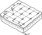
На фиг. 1 представлена схема осуществления предлагаемого способа с отработкой верхней зоны вскрышного массива гидроударной установкой и рыхлительно-бульдозерными агрегатами, нижней зоны вскрышного массива с помощью ГРУ и НРС; на фиг. 2 - схема размещения точек приложения ударной нагрузки при ослаблении массива верхней зоны вскрышки. In FIG. 1 shows a diagram of the implementation of the proposed method with the development of the upper zone of the overburden array by a water hammer installation and cultivating bulldozer units, the lower zone of the overburden array using GRU and LDCs; in FIG. 2 is a diagram of the placement of points of application of shock load when the array of the upper overburden zone is weakened
Способ осуществляется следующим образом. Вскрышной массив, расположенный над блочным массивом, разбивают на верхнюю и нижнюю зоны. После чего массив верхней зоны ослабляют последовательно, воздействуя ударной нагрузкой гидроударной установки 1 при ее продольном перемещении по поверхности массива. При этом точки 2 приложения ударной нагрузки расположены в шахматном порядке по фронту работ. Причем расстояние между проходами определяют по формуле
a= 
b = (2,2÷2,4)а.The method is as follows. The overburden array located above the block array is divided into upper and lower zones. After that, the array of the upper zone is weakened sequentially, acting by the shock load of the
a =
b = (2.2 ÷ 2.4) a.
Эффект разрушения массива в горизонтальной и вертикальной плоскостях достигается за счет формирования магист- ральных трещин 3 между точками приложения ударной нагрузки. The effect of destruction of the massif in horizontal and vertical planes is achieved due to the formation of main cracks 3 between the points of application of the shock load.
Удельная объемная энергия ослабления (разрушения) массива породы (ао) выбирается с учетом свойств горной породы, составляющей массив верхней зоны вскрыши, которые приведены ниже:
Сильнотрещиноватые Трещиноватые Слаботрещиноватые
породы породы, Дж/м3 породы, Дж/м3
Ослабление (20 - 30)˙105 (30 - 50)˙105
пород не
требуется
Дальнейший процесс разрушения массива верхней зоны вскрыши в горизонтальной и вертикальной плоскостях достигается за счет последовательных проходов 4 рыхлительно-бульдозерных агрегатов 5 параллельно проходам гидроударной установки 1. При этом операцию рыхления ослабленного массива горной породы производят внедрением зуба рыхлительно-бульдозерного агрегата 5 в массив, начиная от крайних лунок, образованных после нанесения ударов гидроударной установки 1.The specific volumetric energy of attenuation (destruction) of the rock mass (а о ) is selected taking into account the properties of the rock constituting the mass of the upper overburden zone, which are given below:
Strongly Fractured Fractured Weakly Fractured
breed rocks, J / m 3 rocks, J / m 3
Attenuation (20 - 30) ˙10 5 (30 - 50) ˙10 5
no breeds
required
The further process of destruction of the mass of the upper overburden zone in the horizontal and vertical planes is achieved by
После операции рыхления производится складирование горной породы в штабель рыхлительно-бульдозерным агрегатом 5 с набором и перемещением горной породы бульдозерным щитом горизонтальными слоями, продольными или поперечными заходками относительно фронта работ. After the operation of loosening, the rock is stored in a pile by the loosening-
Отработка массива нижней зоны скальной вскрыши до блочного массива производится способом направленного откола с использованием гидрораскалывающих устройств (ГРУ) 6 для прочных трещиноватых пород, либо невзрывчатых разрушающих средств (НРС) 6 для прочных слаботрещино- ватых пород, размещаемых в шпурах, пробуриваемых в плоскости откола на всю мощность массива нижней зоны вскрыши при наличии выраженной горизонтальной трещиноватости в массиве или шпурах, пробуриваемых в горизонтальной плоскости по подошве нижней зоны при отсутствии природных ориентированных трещин в массиве. The mining of the array of the lower zone of overburden to the block massif is carried out by the directional spallation method using hydraulic cracking devices (GRU) 6 for strong fractured rocks, or non-explosive destructive means (LDCs) 6 for durable weakly fractured rocks placed in boreholes drilled in the breakaway plane the entire power of the array of the lower overburden zone in the presence of pronounced horizontal fracturing in the array or holes drilled in the horizontal plane at the bottom of the lower zone in the absence of oriented cracks in the array.
Отработка массива нижней зоны скальной вскрыши пород средней и малой прочности производится камнерезными машинами с гибким или жестким рабочим органом вертикальными и горизонтальными пропилами в массиве одним уступом, либо подуступами, когда имеются ограничения по техническим параметрам камнерезных машин (с жестким режущим рабочим органом). Mining of the massif of the lower zone of overburden of rocks of medium and low strength is carried out by stone-cutting machines with flexible or rigid working body vertical and horizontal cuts in the array with one ledge, or sub-steps, when there are restrictions on the technical parameters of stone-cutting machines (with a rigid cutting working body).
Предлагаемый способ позволяет вести работу без технических перерывов; снижает уровень динамического воздействия на массив, энергозатраты; обеспечивает сохранность нижележащих пород; улучшает качество добываемых блоков облицовочного камня, снижает трудоемкость удаления скальной вскрыши. The proposed method allows you to work without technical interruptions; reduces the level of dynamic effects on the array, energy consumption; ensures the safety of underlying rocks; improves the quality of the extracted blocks of facing stone, reduces the complexity of removing rock overburden.
Claims (1)
a=

где A - энергия единичного удара установки, Дж;
n - количество ударов в одной точке;
a0 - удельная объемная энергия ослабления массива породы, Дж/м3;
C - мощность ослабляемого слоя,
а расстояние b между соседними точками приложения ударной нагрузки устанавливают из соотношения
b = (2,2 - 2,4) · a,
а рыхление горной породы производят параллельными проходами.METHOD FOR REMOVING ROCK OVERFLOW, including violation of rock integrity by impact loading, loosening by longitudinal passages of the cultivating aggregate, stacking of rock mass, characterized in that, in order to reduce the cost of developing rocks while reducing the complexity of its removal, the places of application of impact load are placed in a checkerboard pattern order, the distance a between adjacent passages of a hydraulic hammer installation is determined from the expression
a =
where A is the energy of a single impact of the installation, J;
n is the number of strokes at one point;
a 0 is the specific volumetric energy of attenuation of the rock mass, J / m 3 ;
C is the power of the weakened layer,
and the distance b between adjacent points of application of shock load is determined from the ratio
b = (2.2 - 2.4)
and loosening of the rock produce parallel passages.
Priority Applications (1)
| Application Number | Priority Date | Filing Date | Title |
|---|---|---|---|
| SU4791586 RU2012807C1 (en) | 1989-12-28 | 1989-12-28 | Method for removal of hard rock overburden |
Applications Claiming Priority (1)
| Application Number | Priority Date | Filing Date | Title |
|---|---|---|---|
| SU4791586 RU2012807C1 (en) | 1989-12-28 | 1989-12-28 | Method for removal of hard rock overburden |
Publications (1)
| Publication Number | Publication Date |
|---|---|
| RU2012807C1 true RU2012807C1 (en) | 1994-05-15 |
Family
ID=21496299
Family Applications (1)
| Application Number | Title | Priority Date | Filing Date |
|---|---|---|---|
| SU4791586 RU2012807C1 (en) | 1989-12-28 | 1989-12-28 | Method for removal of hard rock overburden |
Country Status (1)
| Country | Link |
|---|---|
| RU (1) | RU2012807C1 (en) |
Cited By (1)
| Publication number | Priority date | Publication date | Assignee | Title |
|---|---|---|---|---|
| RU2678752C1 (en) * | 2016-11-10 | 2019-01-31 | Бауэр Машинен Гмбх | Method of development of deposit and opencast |
-
1989
- 1989-12-28 RU SU4791586 patent/RU2012807C1/en active
Cited By (1)
| Publication number | Priority date | Publication date | Assignee | Title |
|---|---|---|---|---|
| RU2678752C1 (en) * | 2016-11-10 | 2019-01-31 | Бауэр Машинен Гмбх | Method of development of deposit and opencast |
Similar Documents
| Publication | Publication Date | Title |
|---|---|---|
| RU2012807C1 (en) | Method for removal of hard rock overburden | |
| RU2392434C1 (en) | Method to provide for stability of high ledges | |
| RU2134786C1 (en) | Method for saving sections of development workings | |
| RU1153628C (en) | Method of stone quarry | |
| RU2079657C1 (en) | Method of extraction of rock benches | |
| RU2004803C1 (en) | Method for opencast mining of mineral deposits | |
| RU2553723C1 (en) | Method of remote coal extraction at edge seams in open-cast and device to this end | |
| RU2247245C1 (en) | Method for extraction of steep-falling and slanting deposits of low and average power with partial backfill | |
| RU2731967C2 (en) | Destructing tool and rock destruction method | |
| RU2099529C1 (en) | Method for preparing rocks for excavation | |
| SU836364A1 (en) | Method of preventing dynamic phenomena at working of coal beds | |
| SU1308761A1 (en) | Method and apparatus for mining mineral deposits with hard rock inclusions | |
| RU1789687C (en) | Method for mining natural stone blocks | |
| RU2810374C1 (en) | Method of strengthening ledge berm | |
| SU1083662A1 (en) | Method of mining steep-slope ore-bodies | |
| SU1719639A1 (en) | Method to work hard rock | |
| SU875038A1 (en) | Method of afterworking of sloping mineral deposits | |
| RU2078216C1 (en) | Method for prevention of rock bursts and increase of roof cavability | |
| RU2187647C1 (en) | Method of softening of surface layer of opencast benches in seasonal ground freezing | |
| RU2086767C1 (en) | Method for development of flat deposits | |
| SU1723326A1 (en) | Method for recultivation of land broken by open-pit mining | |
| RU2278263C1 (en) | Method for mineral excavation from open-cast mine | |
| SU1208243A1 (en) | Method of roof control in longwalls when working mineral beds at great depth | |
| RU2386813C1 (en) | Method of solid minerals borehole hydro-mining | |
| SU711294A1 (en) | Method of mining stone blocks for walls |