RU2017251C1 - Thermal relay - Google Patents
Thermal relay Download PDFInfo
- Publication number
- RU2017251C1 RU2017251C1 SU5041764A RU2017251C1 RU 2017251 C1 RU2017251 C1 RU 2017251C1 SU 5041764 A SU5041764 A SU 5041764A RU 2017251 C1 RU2017251 C1 RU 2017251C1
- Authority
- RU
- Russia
- Prior art keywords
- thermal relay
- thermal
- switch
- change
- rigid rod
- Prior art date
Links
- 239000000126 substance Substances 0.000 claims abstract description 22
- 230000007246 mechanism Effects 0.000 claims abstract description 6
- 238000004891 communication Methods 0.000 claims description 2
- 238000004870 electrical engineering Methods 0.000 abstract description 3
- 230000006835 compression Effects 0.000 abstract 1
- 238000007906 compression Methods 0.000 abstract 1
- 230000008878 coupling Effects 0.000 abstract 1
- 238000010168 coupling process Methods 0.000 abstract 1
- 238000005859 coupling reaction Methods 0.000 abstract 1
- 238000009434 installation Methods 0.000 description 2
- 239000007788 liquid Substances 0.000 description 2
- 239000000463 material Substances 0.000 description 2
- 238000002844 melting Methods 0.000 description 2
- 230000008018 melting Effects 0.000 description 2
- 230000007420 reactivation Effects 0.000 description 2
- 230000035939 shock Effects 0.000 description 2
- 230000001960 triggered effect Effects 0.000 description 2
- 239000004484 Briquette Substances 0.000 description 1
- 230000009471 action Effects 0.000 description 1
- 239000012530 fluid Substances 0.000 description 1
- 238000010438 heat treatment Methods 0.000 description 1
- 238000004519 manufacturing process Methods 0.000 description 1
- 239000000155 melt Substances 0.000 description 1
- 238000013021 overheating Methods 0.000 description 1
- 230000036316 preload Effects 0.000 description 1
- 230000004044 response Effects 0.000 description 1
- 238000007789 sealing Methods 0.000 description 1
- 230000035945 sensitivity Effects 0.000 description 1
Images
Landscapes
- Fuses (AREA)
- Thermally Actuated Switches (AREA)
Abstract
Description
Изобретение относится к электротехнике, в частности к температурным реле с принудительным возвратом, содержащим термочувствительное плавкое вещество и предназначенным для защиты электротеплового оборудования от перегрева при аварийных режимах работы. The invention relates to electrical engineering, in particular to temperature relays with forced return containing a thermosensitive fusible substance and designed to protect electrical equipment from overheating during emergency operation.
Известен тепловой выключатель с термочувствительным плавким веществом многократного срабатывания [1], содержащий рычаг ручного управления, электрический переключатель, поршень в гильзе с плавким веществом и дугообразную перехлопывающую пластину. Known thermal switch with a heat-sensitive fusible substance multiple operation [1], containing a manual control lever, an electric switch, a piston in a sleeve with a fusible substance and an arched overlapping plate.
Недостатком этого выключателя является его низкая надежность, так как перехлопывающая пластина является неустойчивым элементом и может самопроизвольно перехлопывать при толчках, ударах, тряске и вибрации. The disadvantage of this switch is its low reliability, since the slam-shut plate is an unstable element and can spontaneously slam during shocks, bumps, shaking and vibration.
Известен тепловой плавкий переключатель [2], содержащий неподвижные и подвижные поворачивающиеся контакты, поворотную ось, храповик, плавкое вещество и цилиндрические пружины кручения, который способен многократно срабатывать вручную возвращаться в исходное положение. Known thermal fusible switch [2], containing fixed and movable rotating contacts, a rotary axis, ratchet, fusible substance and cylindrical torsion springs, which is able to manually operate repeatedly to return to its original position.
Известен также температурный предохранитель многократного действия [3], содержащий поворотные контакты, поворотную ось, храповик, втулку, связанную с поворотной осью брикетом из плавкого вещества, спиральную возвратную пружину кручения и цилиндрическую пружину поджатия. Multiple-action temperature fuse [3] is also known, comprising rotary contacts, a rotary axis, a ratchet, a sleeve associated with a rotary axis of a fusible material briquette, a spiral torsion return spring and a preload cylindrical spring.
Недостатками устройств [2] и [3] являются их сложность, большое число конструктивных элементов и размещение термочувствительного плавкого вещества внутри устройства, из-за чего при нагреве плавкого вещества нагреваются все элементы конструкции, в том числе и электрические переключатели. Такие устройства, не имеющие дистанционной кинематической связи с термочувствительным элементом, приходится устанавливать непосредственно в зоне контролируемой температуры и подводить в эту зону электрические провода, что невозможно при контроле высоких температур и в жидких средах, как, например, в электроводонагревателях, самоварах и чайниках. The disadvantages of the devices [2] and [3] are their complexity, a large number of structural elements and the placement of a thermosensitive fusible substance inside the device, which is why when heating the fusible substance all the structural elements are heated, including electrical switches. Such devices that do not have remote kinematic connection with a thermosensitive element must be installed directly in the zone of controlled temperature and electric wires must be connected to this zone, which is impossible when controlling high temperatures and in liquid media, such as in electric heaters, samovars and kettles.
Известен тепловой выключатель [4], содержащий в одном корпусе плавкое вещество, размещенное между корпусом и торцовой поверхностью поворотной оси, рычаг управления, пружину, храповик и электрические контакты, один из которых размещен на подвижном рычаге управления, а другой - на корпусе. Known thermal switch [4], containing in one housing a fusible substance located between the housing and the end surface of the rotary axis, control lever, spring, ratchet and electrical contacts, one of which is located on the movable control lever, and the other on the body.
Несмотря на то, что плавкое вещество приближено к корпусу для повышения чувствительности к температуре, в данном устройстве нагреваются все элементы конструкции и электрические элементы, так как устройство не имеет возможности дистанционно контролировать температуру. Устройство имеет сложную конструкцию и не удобно для монтажа на объектах. Despite the fact that the fusible substance is close to the body to increase sensitivity to temperature, in this device all structural elements and electrical elements are heated, since the device does not have the ability to remotely control the temperature. The device has a complex structure and is not convenient for installation on objects.
Наиболее простой и малогабаритной конструкцией отличается тепловое реле [5] , содержащее корпус, плавкое вещество между корпусом и одним из двух соосных дисков храпового механизма, поворотную ось с пружиной кручения и переключатель контактов поворотного типа. The simplest and smallest design is the thermal relay [5], which contains a housing, a fusible material between the housing and one of the two coaxial ratchet disks, a rotary axis with a torsion spring, and a rotary type contact switch.
Данное тепловое реле пригодно, например, для установки на корпусах электродвигателей, на жарочных поверхностях, но также непригодно для объектов, где требуется дистанционно контролировать температуру, особенно для объектов с жидкой средой или при очень высоких температурах объекта. Общим недостатком аналогов [2] , [3], [4] и [5] является то, что плавкое вещество размещено свободно между элементами конструкции, а не содержится в замкнутом герметизированном термопатроне. В случае срабатывания термореле при аварийном режиме, как правило, температура объекта продолжает повышаться из-за инерционности объектов и доходит до предела, значительно превышающего температуру плавления вещества. При этом плавкое вещество становится настолько текучим, что может полностью вытекать через щели и зазоры. В результате этого термореле может сработать один или несколько раз и прекратит выполнение своих функций. Известные аналоги не позволяют использовать их для комбинации различных видов коммутации электроцепей (замыкание, размыкание или переключение), а также не содержат элемента, визуально сигнализирующего о срабатывании их в аварийном режиме работы объекта. This thermal relay is suitable, for example, for installation on electric motor housings, on frying surfaces, but is also unsuitable for objects where it is necessary to remotely control the temperature, especially for objects with a liquid medium or at very high object temperatures. A common drawback of analogues [2], [3], [4] and [5] is that the fusible substance is placed freely between the structural elements, and is not contained in a closed sealed thermo cartridge. In the event of a thermal relay tripping during emergency operation, as a rule, the temperature of the object continues to increase due to the inertia of the objects and reaches a limit well above the melting point of the substance. In this case, the fusible substance becomes so fluid that it can completely leak out through slots and gaps. As a result of this, the thermal relay may trip one or more times and cease to fulfill its functions. Known analogues do not allow using them for a combination of different types of switching electrical circuits (short circuit, opening or switching), and also do not contain an element that visually signals that they are triggered in emergency operation of the object.
Наиболее близким по технической сущности к заявляемому устройству является выбранный прототипом тепловой выключатель [6], содержащий поршень с возвратной пружиной, размещенные в термопатроне и удерживаемые плавким веществом, дугообразную перехлопывающую пружину с кнопкой для повторного включения, связанной с переключателем электрических контактов, промежуточный рычаг и дистанционный гибкий трос, установленный между поршнем и одним концом перехлопывающей пружины. Данная конструкция позволяет дистанционно контролировать температуру и устанавливать в различных местах объекта термочувствительную и электрокоммутирующую части теплового выключателя. The closest in technical essence to the claimed device is the selected thermal prototype switch [6], containing a piston with a return spring, placed in the thermocouple and held by a fusible substance, an arcuate slam spring with a button for re-activation associated with the switch of electrical contacts, an intermediate lever and a remote a flexible cable installed between the piston and one end of the recoil spring. This design allows you to remotely control the temperature and install heat-sensitive and electro-switching parts of the thermal switch in various places of the object.
Недостатками известного выключателя являются сложное конструктивное исполнение, большое число деталей и большие габариты термопатрона, где размещается поршень, возвратная пружина и плавкое вещество. Из-за больших габаритных размеров термопатрона увеличивается тепловая инерционность и время срабатывания. Уменьшение термопатрона вызывает технологические трудности при изготовлении, так как становится невозможным ввести в термопатрон поршень, пружину и плавкое вещество. Кроме того, возможна низкая надежность теплового выключателя при эксплуатации в условиях вибрации, тряски и ударов, когда перехлопывающая пружина может самопроизвольно срабатывать. The disadvantages of the known switch are a complex design, a large number of parts and large dimensions of the thermocouple, which houses the piston, return spring and fusible substance. Due to the large overall dimensions of the thermal cartridge, the thermal inertia and response time increase. Reducing the thermocouple causes technological difficulties in manufacturing, since it becomes impossible to introduce a piston, spring and fusible substance into the thermocouple. In addition, a low reliability of the thermal switch is possible during operation in conditions of vibration, shaking and shock, when the recoil spring can spontaneously operate.
Сущность изобретения заключается в том, что в термореле механизм принудительного возврата выполнен в виде четырехгранной пустотелой кнопки, во внутренней полости которой размещена возвратная пружина, а по периметру наружной кромки размещена токопроводящая пластина, шунтирующая контактные пластины электрического переключателя, устанавливаемые в различных комбинациях. Дистанционная кинематическая связь выполнена в виде жесткого стержня, размещенного в дистанционной трубке термопатрона и одним своим концом защемленного на конце трубки плавким веществом, на другом конце которого закреплен храповой элемент, входящий в зацепление с фиксирующей планкой, выполненной за одно целое с кнопкой возврата. Такое техническое решение позволяет выполнить термореле компактным и малогабаритным с возможностью коммутировать при срабатывании электрические цепи на размыкание, на замыкание и на переключение электрических контактов, а также визуально определять состояние термореле и объекта в целом. The essence of the invention lies in the fact that in the thermal relay the forced return mechanism is made in the form of a tetrahedral hollow button, in which the return spring is placed, and a conductive plate is placed around the perimeter of the outer edge, which shunts the contact plates of the electric switch, which can be installed in various combinations. The remote kinematic connection is made in the form of a rigid rod, placed in a remote tube of the thermocouple and with one end of it clamped on the end of the tube by a fusible substance, on the other end of which a ratchet element is fixed, which engages with a fixing bar made in one piece with the return button. Such a technical solution allows the thermal relay to be compact and small-sized with the ability to switch electrical circuits when opened, to open, close and switch electrical contacts, as well as visually determine the state of the thermal relay and the entire object.
Сопоставимый анализ с прототипом показывает, что в заявленном объекте дистанционная кинематическая связь имеет более простую и надежную конструкцию, надежно фиксирующую переключающий механизм в условиях тряски и вибрации, а компактный переключатель существенно расширяет функции термореле, что в совокупности позволяет сделать вывод о соответствии заявляемого технического решения критерию "новизна". Анализ известных аналогов в областях электротехники и приборостроения позволяет сделать вывод об отсутствии в них признаков, сходных с отличительными признаками заявляемого устройства, которые могут соответствовать критерию "изобретательский уровень". A comparable analysis with the prototype shows that in the claimed object, remote kinematic communication has a simpler and more reliable design that reliably fixes the switching mechanism under conditions of shaking and vibration, and a compact switch significantly expands the functions of the thermal relay, which together allows us to conclude that the claimed technical solution meets the criterion "novelty". Analysis of well-known analogues in the fields of electrical engineering and instrumentation allows us to conclude that there are no signs in them that are similar to the hallmarks of the claimed device, which may meet the criterion of "inventive step".
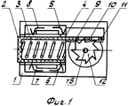
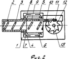
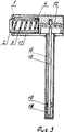
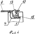
На фиг. 1 изображено термореле, вид со стороны снятой крышки, в положении принудительного включения на рабочий режим; на фиг. 2 - тот же вид термореле, в положении после автоматического срабатывания; на фиг. 3 - термореле в разрезе; на фиг. 4 - вариант исполнения храпового элемента. In FIG. 1 shows a thermal relay, a view from the side of the removed cover, in the forced on position; in FIG. 2 - the same type of thermal relay, in position after automatic operation; in FIG. 3 - sectional thermal relay; in FIG. 4 - embodiment of the ratchet element.
Термореле содержит корпус 1 (фиг. 1, 2, 3), в направляющих которого размещена кнопка 2 принудительного возврата с пружиной 3 и токопроводящей пластиной 4, закрепленной на наружной кромке кнопки 2. В пазах корпуса установлены контактные пластины 5, 6, 7 и 8, позволяющие подключать термореле к различным коммутационным схемам. Одна грань кнопки 2 выполнена с удлинением в виде планки 9, на которой имеются два отверстия в виде пазов и поперечные перемычки 10 и 11, входящие в зацепление с храповым элементом, выполненным, в частности, в виде храпового колеса 12. Храповый элемент может быть выполнен и в виде сектора 13 храпового колеса с одним зубом и пружиной 14 (фиг. 4), что позволяет выполнить термореле еще более компактным. Храповое колесо 12 (фиг. 3) закреплено на конце стержня 15, который размещен в дистанционной трубке 16 термопатрона, которая закреплена на крышке 17. Другой конец стержня 15 защемлен на конце трубки 16 плавким веществом 18, которое предохраняется от утечки при расплавлении уплотнительным кольцом 19. The thermal relay contains a housing 1 (Fig. 1, 2, 3), in the guides of which there is a forced
Термореле работает следующим образом. Thermal relay works as follows.
В рабочем положении (фиг. 1) кнопка 2 принудительно утоплена в полость корпуса 1, а планка 9 своей перемычкой 10 зафиксирована на зубе храпового колеса 12. Храповое колесо неподвижно, так как стержень 15 зафиксирован от поворота плавким веществом 18. При этом пластина 4 шунтирует контактные пластины 5 и 6, коммутирующие рабочую электроцепь объекта. При аварийном состоянии объекта, когда его температура повысится до точки плавления вещества 18, последнее расплавляется и освобождает конец стержня. Под действием усилия пружины 3 храповое колесо 12 поворачивается, а перемычка 10 на планке 9 срывается с зуба храпового колеса и кнопка 2 перемещается пружиной 3 из корпуса 1 наружу (фиг. 2). При этом контактные пластины 5 и 6 переключателя размыкаются, а пластины 7 и 8 замыкаются. Планка 9 при своем движении захватывает перемычкой 11 очередной зуб храпового колеса и фиксирует его в положении, обеспечивающем последующее принудительное включение термореле. В случае выполнения храпового механизма в виде сектора 13 с одним зубом (фиг. 4) на планке 9 достаточно одной перемычки 10 для фиксации планки. Возвращение сектора 13 в исходное положение и его фиксация после срабатывания термореле происходят за счет пружины 14. Повторное включение термореле возможно после затвердения плавкого вещества 18, для чего нажатием на кнопку 2 термореле переводится в рабочее положение (фиг. 1). Таким образом, автоматическое срабатывание термореле может сопровождаться размыканием электроцепи, если использовать только контакты 5 и 6, или замыканием цепи, если использовать контакты 7 и 8, или переключением, если использовать и те и другие пары контактов. Если боковая поверхность кнопки 2 имеет яркий цвет, отличающийся от цвета торцовой поверхности кнопки и корпуса, то положение кнопки визуально сигнализирует о состоянии термореле и объекта. Такое техническое решение позволяет выполнить термореле универсальным и использовать его на различных объектах без конструктивных изменений. In the operating position (Fig. 1), the
Claims (2)
Priority Applications (1)
| Application Number | Priority Date | Filing Date | Title |
|---|---|---|---|
| SU5041764 RU2017251C1 (en) | 1992-05-12 | 1992-05-12 | Thermal relay |
Applications Claiming Priority (1)
| Application Number | Priority Date | Filing Date | Title |
|---|---|---|---|
| SU5041764 RU2017251C1 (en) | 1992-05-12 | 1992-05-12 | Thermal relay |
Publications (1)
| Publication Number | Publication Date |
|---|---|
| RU2017251C1 true RU2017251C1 (en) | 1994-07-30 |
Family
ID=21603995
Family Applications (1)
| Application Number | Title | Priority Date | Filing Date |
|---|---|---|---|
| SU5041764 RU2017251C1 (en) | 1992-05-12 | 1992-05-12 | Thermal relay |
Country Status (1)
| Country | Link |
|---|---|
| RU (1) | RU2017251C1 (en) |
Cited By (2)
| Publication number | Priority date | Publication date | Assignee | Title |
|---|---|---|---|---|
| RU2142659C1 (en) * | 1998-09-11 | 1999-12-10 | Жидков Игорь Алексеевич | Thermostatic switch |
| RU202733U1 (en) * | 2020-11-26 | 2021-03-03 | Общество с ограниченной ответственностью Научно-производственное предприятие "Микропроцессорные технологии" | THERMAL PROTECTION RELAY |
-
1992
- 1992-05-12 RU SU5041764 patent/RU2017251C1/en active
Non-Patent Citations (6)
| Title |
|---|
| 1. Авторское свидетельство СССР N 702423, кл. H 01H 37/76, 1979. * |
| 2. Патент Великобритании СССР N 2005477, кл. H 01H 37/76, 1979. * |
| 3. Заявка Японии N 59-39848, кл. H 01H 37/76, 1984. * |
| 4. Авторское свидетельство СССР N 1412510, кл. H 01H 37/76, 1986. * |
| 5. Авторское свидетельство СССР N 1624553, кл. H 01H 37/76, 1991. * |
| 6. Авторское свидетельство СССР N 819842, кл. H 01H 37/76, 1981. * |
Cited By (2)
| Publication number | Priority date | Publication date | Assignee | Title |
|---|---|---|---|---|
| RU2142659C1 (en) * | 1998-09-11 | 1999-12-10 | Жидков Игорь Алексеевич | Thermostatic switch |
| RU202733U1 (en) * | 2020-11-26 | 2021-03-03 | Общество с ограниченной ответственностью Научно-производственное предприятие "Микропроцессорные технологии" | THERMAL PROTECTION RELAY |
Similar Documents
| Publication | Publication Date | Title |
|---|---|---|
| US4307370A (en) | Heat sensitive circuit breaker employing meltable material | |
| US6741159B1 (en) | Fail-safe assembly for coacting contacts in a current-carrying system, apparatus or component | |
| US4084147A (en) | Normally open, thermal sensitive electrical switching device | |
| US4053859A (en) | Temperature sensitive switch | |
| US4352082A (en) | Thermal fuse | |
| CA1089518A (en) | Thermally actuated electrical switch | |
| RU2017251C1 (en) | Thermal relay | |
| EP3940738B1 (en) | Mechanical operating assembly for a bistable relay and a bistable relay assembly | |
| US3885222A (en) | Thermostat construction | |
| US4092624A (en) | Thermostat assembly | |
| US4160968A (en) | Normally open, thermal sensitive electrical switching device | |
| GB2185857A (en) | Controls for vessels for heating liquids | |
| SU702423A1 (en) | Thermal switch | |
| JP6991235B2 (en) | Heat-activated mechanical switching device | |
| RU2017250C1 (en) | Thermal relay | |
| GB2193563A (en) | Liquid heater | |
| US4203086A (en) | Temperature-sensitive spiral spring sliding contact device | |
| RU2142659C1 (en) | Thermostatic switch | |
| US2824933A (en) | Miniature switch | |
| US2751462A (en) | Fuse circuit breaker | |
| US4392118A (en) | Thermal overload relay having a N.O. or N.C. contact unit selectively addable in the field | |
| SU819842A2 (en) | Thermal switch | |
| RU2027244C1 (en) | Thermostatic switch | |
| RU2020633C1 (en) | Thermostatic switch | |
| SU1089661A1 (en) | Temperature-sensitive switch |