RU2024931C1 - Device for performing discrete orthogonal conversions - Google Patents
Device for performing discrete orthogonal conversions Download PDFInfo
- Publication number
- RU2024931C1 RU2024931C1 SU4881095A RU2024931C1 RU 2024931 C1 RU2024931 C1 RU 2024931C1 SU 4881095 A SU4881095 A SU 4881095A RU 2024931 C1 RU2024931 C1 RU 2024931C1
- Authority
- RU
- Russia
- Prior art keywords
- inputs
- row code
- input
- multipliers
- adders
- Prior art date
Links
Images
Landscapes
- Complex Calculations (AREA)
Abstract
Description
Изобретение относится к вычислительной технике, в частности к цифровой обработке радио,- гидро- и звуколокационных сигналов, и может быть применено при построении быстродействующих Фурье-процессоров. The invention relates to computing, in particular to digital processing of radio, hydro and sonar signals, and can be used in the construction of high-speed Fourier processors.
Цель предлагаемого изобретения - повышение быстродействия устройства. The purpose of the invention is to increase the speed of the device.
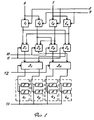
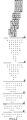
На фиг. 1 представлена функциональная схема устройства для выполнения дискретных ортогональных преобразований; фиг.2 - преобразование многострочной матрицы в сумматоре двухрядного кода в двухрядный код с помощью трехвходовых одноразрядных сумматоров при разрядности входных данных m = 4. In FIG. 1 is a functional diagram of a device for performing discrete orthogonal transformations; figure 2 - conversion of a multi-line matrix in the adder of a two-row code into a two-row code using three-input single-digit adders with a bit of input data m = 4.
Устройство (фиг.1) содержит первый 11, второй 12, третий 13, и четвертый 14 умножители двухрядного кода, первый 21, второй 22, третий 23 и четвертый 24 сумматоры двухрядного кода, первый 31 и второй 32 коммутаторы, первый 41, второй 42, третий 43 и четвертый 44 блоки регистров, состоящие из регистров 5, входы мнимой 6 и реальной 7 частей второго операнда, входы реальной 8 и мнимой 9 частей коэффициента устройства, входы реальной 10 и мнимой 11 частей первого операнда, управляющий вход 12 и тактовый вход устройства 13.The device (figure 1) contains the first 1 1 , second 1 2 , third 1 3 , and fourth 1 4 multipliers of the two-row code, the first 2 1 , second 2 2 , third 2 3 and the fourth 2 4 adders of the two-row code, the first 3 1 and second 3 2 switches, first 4 1 , second 4 2 , third 4 3 and fourth 4 4 register blocks, consisting of
Устройство работает следующим образом. The device operates as follows.
При выполнении прямого преобразования Фурье на первый вход 12 устройства подается нулевой сигнал, при выполнении обратного преобразования Фурье этот сигнал должен быть единичным. В остальном работа устройства в обоих режимах одинакова, поэтому рассмотрим режим прямого преобразования Фурье. When performing the direct Fourier transform, a zero signal is supplied to the
На входы 6 и 7 устройства поступают мнимая ImBi и действительная ReBi части второго операнда Bi, на входы 8 и 9 - действительная ReWi и мнимая ImWi части коэффициента устройства, на входы 10 и 11 - действительная ReAi и мнимая ImAi части второго операнда Ai устройства. В результате умножения на выходах первого 11, второго 12, третьего 13 и четвертого 14 умножителей двухрядного кода будут сформированы многострочные матрицы частичных произведений соответственно ImBi . ReWi, ReBi . .ReWi, ImBi .ImWi и ReBi .ImWi. С выходов умножителей двухрядного кода многострочные матрицы частичных произведений по шинам многострочного кода поступают на сумматоры двухрядного кода, на входы которых также поступают соответствующие коды первого операнда. Таким образом, на входе сумматора двухрядного кода 2i будет сформирована многострочная кодовая матрица, вид которой соответствует позиции 1 на фиг.2. Многострочная кодовая матрица последовательно преобразуется сумматором двухрядного кода в двухрядный код, этапы преобразования изображены соответствующими позициями на фиг.2.The imaginary I m B i and the real R e B i parts of the second operand B i go to the
На выходах первого 21, второго 22, третьего 23 и четвертого 24 сумматоров двухрядного кода будут образованы двухрядные коды соответственно
ImAi + ImBi ˙ReWi + ReBi ˙ImWi (1)
ReAi + ReBi ˙ReWi - (ImBi ˙ImWi) (2)
ReAi - (ReBi˙ ReWi) + ImBi ˙ImWi (3)
ImAi - (imBi ˙ReWi) - (ReBi ˙ImWi) (4)
Коды выражений, обозначенных круглыми скобками, подаются на инверсные входы одноразрядных сумматоров двухрядного кода 2i, что необходимо для реализации операции вычитания в формулах (2) - (4). По тактовым сигналам значения выражений (1) и (4), соответствующие коды ImAi+1 и ImBi+1, через первый коммутатор будут записаны в первый 41 и второй 42 блоки регистров, а значения выражений (2) и (3), соответствующие кодам ReAi+1 и ReBi+1, через второй коммутатор будут записаны в третий 43 и четвертый 44 блоки регистров.At the outputs of the first 2 1 , second 2 2 , third 2 3 and fourth 2 4 adders of the two-row code, two-row codes will be generated, respectively
I m A i + I m B i ˙ R e W i + R e B i ˙ I m W i (1)
R e A i + R e B i ˙ R e W i - (I m B i ˙ I m W i ) (2)
R e A i - (R e B i ˙ R e W i ) + I m B i ˙ I m W i (3)
I m A i - (i m B i ˙ R e W i ) - (R e B i ˙I m W i ) (4)
Codes of expressions indicated by parentheses are fed to the inverse inputs of single-digit adders of a two-
При выполнении обратного преобразования Фурье под воздействием единичного сигнала на первый и второй коммутаторы и тактовых сигналов в первый 41, второй 42, третий 43 и четвертый 44 блоки регистров производится запись кодов соответственно ImBi+1 ImAi+1, ReBi+1, ReAi+1.When performing the inverse Fourier transform under the influence of a single signal on the first and second switches and clock signals in the first 4 1 , second 4 2 , third 4 3 and fourth 4 4 blocks of registers, codes are recorded respectively I m B i + 1 I m A i + 1 , R e B i + 1 , R e A i + 1 .
Claims (1)
Priority Applications (1)
| Application Number | Priority Date | Filing Date | Title |
|---|---|---|---|
| SU4881095 RU2024931C1 (en) | 1990-11-05 | 1990-11-05 | Device for performing discrete orthogonal conversions |
Applications Claiming Priority (1)
| Application Number | Priority Date | Filing Date | Title |
|---|---|---|---|
| SU4881095 RU2024931C1 (en) | 1990-11-05 | 1990-11-05 | Device for performing discrete orthogonal conversions |
Publications (1)
| Publication Number | Publication Date |
|---|---|
| RU2024931C1 true RU2024931C1 (en) | 1994-12-15 |
Family
ID=21544453
Family Applications (1)
| Application Number | Title | Priority Date | Filing Date |
|---|---|---|---|
| SU4881095 RU2024931C1 (en) | 1990-11-05 | 1990-11-05 | Device for performing discrete orthogonal conversions |
Country Status (1)
| Country | Link |
|---|---|
| RU (1) | RU2024931C1 (en) |
-
1990
- 1990-11-05 RU SU4881095 patent/RU2024931C1/en active
Non-Patent Citations (3)
| Title |
|---|
| 1. Авторское свидетельство СССР N 750494, кл. G 06F 15/332, 1978. * |
| 2. Авторское свидетельство СССР N 1013971, кл. G 06F 15/332, 1981. * |
| 3. Авторское свидетельство СССР N 1233168, кл. G 06f 15/332, 1984. * |
Similar Documents
| Publication | Publication Date | Title |
|---|---|---|
| US5226171A (en) | Parallel vector processing system for individual and broadcast distribution of operands and control information | |
| US5081573A (en) | Parallel processing system | |
| US4228498A (en) | Multibus processor for increasing execution speed using a pipeline effect | |
| EP0329023A3 (en) | Apparatus for performing digital signal processing including fast fourier transform radix-4 butterfly computations | |
| EP0212571A3 (en) | Method and circuit for performing discrete transforms | |
| KR880006617A (en) | Right angle conversion handler | |
| EP0171595A3 (en) | Floating point arithmetic unit | |
| JPS6132437Y2 (en) | ||
| JPS61160176A (en) | Vector processing device | |
| KR880014470A (en) | Apparatus and method for performing shift operation in multiplier array circuit | |
| WO2000059112A2 (en) | Multiplier circuit | |
| JPS54159831A (en) | Adder and subtractor for numbers different in data length using counter circuit | |
| Powell et al. | Signal processing with bit-serial word-parallel architectures | |
| US6249799B1 (en) | Selective carry boundary | |
| JPS5748141A (en) | Address conversion system | |
| SU1661760A1 (en) | Arc tan function calculator | |
| JPH01251133A (en) | Multiplying circuit and method | |
| Torode et al. | The logic machine: A modular computer design system | |
| SU1377871A1 (en) | Fast walsh-hadamard transform device | |
| SU1001085A1 (en) | Device for computing complex number modulus | |
| SU572785A1 (en) | Adder for adding two m-digit numbers | |
| JPS6259828B2 (en) | ||
| JP2696903B2 (en) | Numerical calculator | |
| SU1013971A1 (en) | Fast fourier transform device | |
| RU2001428C1 (en) | Adding device |