RU2031237C1 - Adsorber - Google Patents
Adsorber Download PDFInfo
- Publication number
- RU2031237C1 RU2031237C1 SU5060953A RU2031237C1 RU 2031237 C1 RU2031237 C1 RU 2031237C1 SU 5060953 A SU5060953 A SU 5060953A RU 2031237 C1 RU2031237 C1 RU 2031237C1
- Authority
- RU
- Russia
- Prior art keywords
- filler
- adsorber
- tank
- fuel
- pipe
- Prior art date
Links
- 239000000446 fuel Substances 0.000 claims abstract description 30
- 239000000945 filler Substances 0.000 claims abstract description 24
- 239000007791 liquid phase Substances 0.000 claims abstract description 16
- 239000002828 fuel tank Substances 0.000 claims abstract description 7
- 239000011148 porous material Substances 0.000 claims abstract description 7
- 238000009423 ventilation Methods 0.000 claims abstract description 7
- 239000000463 material Substances 0.000 claims abstract description 4
- 239000003463 adsorbent Substances 0.000 claims description 13
- 231100000419 toxicity Toxicity 0.000 claims description 4
- 230000001988 toxicity Effects 0.000 claims description 4
- 229920000049 Carbon (fiber) Polymers 0.000 claims description 3
- 239000004917 carbon fiber Substances 0.000 claims description 3
- VNWKTOKETHGBQD-UHFFFAOYSA-N methane Chemical compound C VNWKTOKETHGBQD-UHFFFAOYSA-N 0.000 claims description 3
- 230000000694 effects Effects 0.000 abstract description 3
- 239000003245 coal Substances 0.000 abstract 1
- -1 e.g. Substances 0.000 abstract 1
- 239000000835 fiber Substances 0.000 abstract 1
- 239000000126 substance Substances 0.000 abstract 1
- 238000010926 purge Methods 0.000 description 14
- 239000007788 liquid Substances 0.000 description 10
- 239000000203 mixture Substances 0.000 description 8
- 239000002250 absorbent Substances 0.000 description 5
- 230000002745 absorbent Effects 0.000 description 5
- 238000011109 contamination Methods 0.000 description 4
- 238000011049 filling Methods 0.000 description 4
- 239000012530 fluid Substances 0.000 description 4
- OKTJSMMVPCPJKN-UHFFFAOYSA-N Carbon Chemical compound [C] OKTJSMMVPCPJKN-UHFFFAOYSA-N 0.000 description 3
- 239000006185 dispersion Substances 0.000 description 3
- 238000010521 absorption reaction Methods 0.000 description 2
- 238000003795 desorption Methods 0.000 description 2
- 238000010586 diagram Methods 0.000 description 2
- 239000002245 particle Substances 0.000 description 2
- 238000001179 sorption measurement Methods 0.000 description 2
- 239000010754 BS 2869 Class F Substances 0.000 description 1
- 238000013459 approach Methods 0.000 description 1
- 238000004140 cleaning Methods 0.000 description 1
- 238000002485 combustion reaction Methods 0.000 description 1
- 238000009833 condensation Methods 0.000 description 1
- 230000005494 condensation Effects 0.000 description 1
- 230000006866 deterioration Effects 0.000 description 1
- 238000001704 evaporation Methods 0.000 description 1
- 230000008020 evaporation Effects 0.000 description 1
- 239000004744 fabric Substances 0.000 description 1
- 239000008187 granular material Substances 0.000 description 1
- 229910002804 graphite Inorganic materials 0.000 description 1
- 239000010439 graphite Substances 0.000 description 1
- 238000003780 insertion Methods 0.000 description 1
- 230000037431 insertion Effects 0.000 description 1
- 238000011089 mechanical engineering Methods 0.000 description 1
- 238000000034 method Methods 0.000 description 1
- 238000002156 mixing Methods 0.000 description 1
- 230000002265 prevention Effects 0.000 description 1
- 238000000746 purification Methods 0.000 description 1
- 238000011084 recovery Methods 0.000 description 1
- 230000000717 retained effect Effects 0.000 description 1
- 231100000331 toxic Toxicity 0.000 description 1
- 230000002588 toxic effect Effects 0.000 description 1
- 239000012808 vapor phase Substances 0.000 description 1
Images

Landscapes
- Supplying Secondary Fuel Or The Like To Fuel, Air Or Fuel-Air Mixtures (AREA)
- Cooling, Air Intake And Gas Exhaust, And Fuel Tank Arrangements In Propulsion Units (AREA)
Abstract
Description
Изобретение относится к машиностроению, в частности к устройствам управления топливных испарений транспортных средств, а именно к адсорберу поглощения паров топлива. The invention relates to mechanical engineering, in particular to control devices for fuel vapor of vehicles, namely to an adsorber for the absorption of fuel vapor.
Известен адсорбер для улавливания паров топлива (патент США N 4193383, кл. F 02 M 59/00, 1980), содержащий заполненный адсорбентом корпус, снабженный патрубком подвода паров топлива и патрубком продувки, расположенными в верхней части корпуса. Поры топлива из топливного бака поступают в корпус, где происходит их поглощение адсорбентом, за счет чего предотвращается попадание паров топлива в атмосферу. Десорбция адсорбента осуществляется путем его продувки атмосферным воздухом за счет вакуума во впускной трубе двигателя, где происходит сжигание паров топлива. Known adsorber for trapping fuel vapor (US patent N 4193383, CL F 02 M 59/00, 1980), containing a housing filled with adsorbent, equipped with a pipe for supplying fuel vapor and a purge pipe located in the upper part of the body. The fuel pores from the fuel tank enter the housing, where they are absorbed by the adsorbent, which prevents the ingress of fuel vapor into the atmosphere. The adsorbent is desorbed by purging it with atmospheric air due to vacuum in the engine intake pipe, where fuel vapor is burned.
В связи с тем, что пары топлива, поступающие из топливного бака, фактически представляют собой смесь из паров топлива, жидкой фазы топлива и воздуха, вследствие конденсации такой адсорбер имеет недостаточные эффективность и ресурс из-за загрязнения адсорбента жидкостью. Due to the fact that the fuel vapor coming from the fuel tank is actually a mixture of fuel vapor, the liquid phase of the fuel and air, as a result of condensation, such an adsorber has insufficient efficiency and resource due to contamination of the adsorbent by the liquid.
Известно устройство (патент США N 4750465, кл. F 02 M 39/00,14.06.88), выбранное в качестве прототипа, которое содержит наполненный адсорбентом корпус, снабженный в нижней части резервуаром для сбора жидкой фазы паров топлива и патрубком продувки, расположенным в центре и вблизи днища резервуара для удаления жидкости из резервуара во впускную трубу двигателя, где жидкость сгорает. A device is known (US patent N 4750465, class F 02 M 39 / 00,14.06.88), selected as a prototype, which contains an adsorbent-filled housing provided in the lower part with a reservoir for collecting the liquid phase of the fuel vapor and a purge pipe located in center and near the bottom of the tank to remove fluid from the tank into the engine inlet pipe, where the liquid burns out.
Однако и это устройство не обладает достаточными ресурсом и эффективностью, так как при наклоне адсорбера от вертикальной оси или вибрациях жидкая фаза выливается из резервуара и загрязняет адсорбент. При этом прекращается удаление жидкой фазы из резервуара во впускную трубу, так как при наклоне жидкая фаза отделяется от нижнего конца патрубка продувки, что приводит к переполнению резервуара и дополнительному загрязнению адсорбента. По этой причине фирмы-изготовители допускают отклонение адсорбера от вертикальной оси не более 4о, что затрудняет размещение адсорбера на автомобиле, при этом не исключается снижение эффективности адсорбера при наклоне автомобиля, который для современных автомобилей предусмотрен не менее 30о. Существенным недостатком известного устройства является также неравномерность удаления жидкой фазы из резервуара во впускную трубу двигателя при продувке адсорбера ввиду того, что частицы жидкости интенсивно захватываются воздухом только при приближении уровня жидкой фазы в резервуаре и входному срезу патрубка продувки, таким образом, удаление жидкой фазы топлива из резервуара во впускную трубу осуществляется порциями, что приводит к перебоям и неустойчивой работе двигателя из-за переобогащения топливовоздушной смеси при попадании порции жидкой фазы топлива во впускную трубу двигателя, а также к ухудшению токсичности, экономичности двигателя и его пусковых качеств.However, this device also does not have sufficient resource and efficiency, since when the adsorber is tilted from the vertical axis or vibrations, the liquid phase spills out of the tank and contaminates the adsorbent. This stops the removal of the liquid phase from the tank into the inlet pipe, since when tilted, the liquid phase is separated from the lower end of the purge pipe, which leads to overflow of the tank and additional contamination of the adsorbent. For this reason, manufacturers have a tolerance adsorber of the vertical axis is not more than about 4, which complicates deployment canister on a car, it does not exclude lower efficiency adsorber when the vehicle is tilted, which is at least 30 provided on modern vehicles. A significant disadvantage of the known device is the uneven removal of the liquid phase from the tank into the engine intake pipe when the adsorber is purged due to the fact that the particles of the liquid are intensely trapped by air only when the level of the liquid phase in the tank approaches and the inlet section of the purge pipe, thus removing the liquid phase of the fuel from the tank into the inlet pipe is carried out in batches, which leads to interruptions and unstable operation of the engine due to re-enrichment of the air-fuel mixture when it enters liquid phase portion of the fuel into the intake pipe of the engine, as well as the toxicity to the deterioration of engine efficiency and startability.
Цель изобретения - улучшение показателей двигателя по токсичности, экономичности, пусковым качествам и устойчивости работы за счет повышения эффективности работы адсорбера. The purpose of the invention is the improvement of engine performance in terms of toxicity, economy, starting qualities and stability by increasing the efficiency of the adsorber.
С этой целью в адсорбере, содержащем цилиндрический корпус, наполнитель из адсорбирующего материала, имеющий верхнюю и нижнюю поверхности, вентиляционный патрубок в верхней части корпуса, сообщающий атмосферу с верхней поверхностью наполнителя, днище корпуса, образующее полость под нижней поверхностью наполнителя, и резервуар, имеющий центральную нижнюю поверхность площадью меньше площади нижней поверхности адсорбента, центральную трубку, соединенную с топливным баком и с впускной трубой двигателя и проходящую через нижнюю поверхность адсорбента, причем входной сред трубы размещен вблизи дна резервуара, в полости с зазором по отношению и нижней поверхности наполнителя размещена вставка, выполненная из капиллярно-пористого материала, например угольного волокна. Такое конструктивное исполнение адсорбера позволяет исключить выливание жидкой фазы из резервуара и загрязнение адсорбента при наклонах адсорбера и обеспечить равномерное удаление жидкой фазы из резервуара во впускную трубу двигателя во время продувки адсорбера как при вертикальном, так и при наклонном расположении адсорбера, тем самым повысить ресурс адсорбера, улучшить характеристики двигателя по токсичности, экономичности, пусковым качеством и устойчивости работы на малых оборотах холостого хода, т.е. повысить эффективность работы адсорбера. To this end, in an adsorber containing a cylindrical body, a filler of absorbent material having upper and lower surfaces, a ventilation pipe in the upper part of the body that communicates the atmosphere with the upper surface of the filler, the bottom of the body forming a cavity under the lower surface of the filler, and a reservoir having a central the lower surface is less than the area of the lower surface of the adsorbent, the central tube connected to the fuel tank and the inlet pipe of the engine and passing through the lower surface be an adsorbent, wherein the input media pipe placed near the bottom of the tank, in the cavity with clearance with respect to both the bottom surface of the filler insert is arranged, made of a capillary-porous material such as carbon fiber. This design of the adsorber eliminates the outflow of the liquid phase from the tank and contamination of the adsorbent during tilts of the adsorber and ensures uniform removal of the liquid phase from the tank into the engine intake pipe during purging of the adsorber both in the vertical and inclined position of the adsorber, thereby increasing the resource of the adsorber, improve engine performance in terms of toxicity, economy, starting quality and stability at low idle speed, i.e. increase the efficiency of the adsorber.
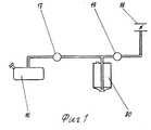
На фиг.1 показана схема системы улавливания паров бензина автомобиля, в которой используется адсорбер по изобретению; на фиг. 2 - показаны возможный вариант конструктивного исполнения адсорбера в осевом разрезе и схема работы в режиме адсорбции (поглощения); на фиг. 3 - показана схема работы адсорбера в режиме десорбции (очистки). 1 shows a diagram of a vehicle gas vapor recovery system in which the adsorber of the invention is used; in FIG. 2 - shows a possible embodiment of the adsorber in axial section and the scheme of operation in the adsorption (absorption) mode; in FIG. 3 - shows a diagram of the operation of the adsorber in the desorption (purification) mode.
Адсорбер содержит пластмассовый корпус 1 цилиндрической формы, внутри которого расположен наполнитель 2 из поглощающего материала, представляющий собой гранулы активированного древесного угля, адсорбирующего поры топлива. Адсорбирующий наполнитель располагается между верхним 3 и нижним 4 экранами, которые образуют верхнюю 5 и нижнюю 6 поверхности адсорбирующего наполнителя 2. Корпус 1 адсорбера закрыт сверху верхней стенкой 7, которая удалена от верхнего экрана 3 и образует с ним воздушное пространство. Верхняя стенка 7 снабжена вентиляционным патрубком 8, с помощью которого верхняя поверхность адсорбирующего наполнителя сообщается с атмосферой. Днище 9 корпуса 1 выполнено в виде конического резервуара, в котором размещена вставка 10 -удерживатель жидкости, представляющий собой капиллярно-пористый материал, например угольное волокно или графитовую ткань. Поверхность вставки 10 удалена от нижней поверхности 6 адсорбирующего наполнителя и от центральной трубки 11 и образуют между ними пространство. Центральная трубка 11 проходит через адсорбирующий наполнитель 2. Входной срез 12 центральной трубки расположен вблизи дна 13 резервуара, а верхний конец соединен с патрубком 14 наполнения и с патрубком 15 продувки. Патрубок наполнения соединен с топливным баком 16 через редукционный клапан 17, а патрубок продувки соединен с впускной трубой 18 двигателя (не показан), где существует вакуум, через контрольный соленоидный клапан 19. The adsorber contains a
Адсорбер работает следующим образом. The adsorber works as follows.
В режиме наполнения (адсорбции) (фиг.1 и 2) под действием давления насыщения паров в топливном баке 16 редукционный клапан 17 открывается и, поскольку при этом контрольный соленоидный клапан 19 блокирует поступление паров во впускную трубу 18 двигателя, то паровая смесь через патрубок 14 наполнения адсорбера 20 движется, как показано стрелками на фиг.2, вниз по центральной трубке 11 и входит в резервуар 9. Жидкая фаза паровой смеси задерживается в резервуаре 9 и впитывается вставкой-удерживателем 10 жидкости за счет капиллярного эффекта. Паровая фаза смеси и воздушный компонент смеси движутся к верхней 5 поверхности наполнителя, как показано стрелками, при этом топливный пар поглощается наполнителем 2, а воздух выходит в атмосферу через вентиляционный патрубок 8. In the filling (adsorption) mode (FIGS. 1 and 2), under the influence of the vapor saturation pressure in the
Благодаря тому, что удерживатель жидкости 10 предотвращает выливание жидкости из резервуара при любых наклонах и вибрациях, обеспечивается надежное предотвращение загрязнения наполнителя жидкостью и таким образом повышаются эффективность работы адсорбера и его ресурс. Due to the fact that the
В режиме очистки (десорбции) (фиг.1 и 3) редукционный клапан 17 закрыт, а контрольный соленоидный клапан 19, сообщающий патрубок 15 продувки центральной трубки 11 с впускной трубой 18 двигателя открыт. In the cleaning (desorption) mode (FIGS. 1 and 3), the
Под действием вакуума во впускной трубе 18 двигателя происходит продувка адсорбера, как показано стрелками на фиг.3. При этом воздух из атмосферы через патрубок 8 вентиляции проходит через весь объем наполнителя 2, десорбируя поглощенные наполнителем поры топлива. Затем воздух проходит через резервуар 9 и вставку 10, захватывает с собой жидкость, накопившуюся во вставке 10, и далее по центральной трубке 11 и патрубку 15 продувки воздух, обогащенный парами и мелкими частицами топлива, поступает во впускную трубу 18 двигателя, где происходит сжигание топлива. Under the action of vacuum in the
Таким образом происходит десорбция наполнителя 2 от паров топлива и очистка вставки 10 от жидкой фазы топлива. При этом в силу капиллярного эффекта вставки удерживателя 10 жидкости продувочный воздух захватывает содержащееся в удерживателе жидкости жидкое топливо в виде мелкой дисперсии и процесс уноса жидкого топлива продувочным воздухом происходит постепенно. Кроме того, при движении топливной дисперсии на участке от резервуара 9 до впускной трубы 18 двигателя происходит дополнительное перемешивание топливной дисперсии с продувочным воздухом и испарение. Поэтому жидкая фаза топлива из резервуара 9 поступает во впускную трубу 18 постепенно в виде гомогенной топливовоздушной смеси, что обеспечивает отсутствие переобогащения топливовоздушной смеси, качественный процесс сгорания и, как следствие, улучшение токсических пусковых характеристик двигателя и устойчивости его работы на малых оборотах холостого хода. In this way, the
Claims (2)
Priority Applications (1)
| Application Number | Priority Date | Filing Date | Title |
|---|---|---|---|
| SU5060953 RU2031237C1 (en) | 1992-05-26 | 1992-05-26 | Adsorber |
Applications Claiming Priority (1)
| Application Number | Priority Date | Filing Date | Title |
|---|---|---|---|
| SU5060953 RU2031237C1 (en) | 1992-05-26 | 1992-05-26 | Adsorber |
Publications (1)
| Publication Number | Publication Date |
|---|---|
| RU2031237C1 true RU2031237C1 (en) | 1995-03-20 |
Family
ID=21612650
Family Applications (1)
| Application Number | Title | Priority Date | Filing Date |
|---|---|---|---|
| SU5060953 RU2031237C1 (en) | 1992-05-26 | 1992-05-26 | Adsorber |
Country Status (1)
| Country | Link |
|---|---|
| RU (1) | RU2031237C1 (en) |
Cited By (6)
| Publication number | Priority date | Publication date | Assignee | Title |
|---|---|---|---|---|
| RU2157911C2 (en) * | 1995-06-30 | 2000-10-20 | Роберт Бош Гмбх | Pump device for system maintaining evaporation of fuel and system using such device |
| RU2157910C2 (en) * | 1995-06-30 | 2000-10-20 | Роберт Бош Гмбх | Pump plant |
| RU2158378C1 (en) * | 1999-02-16 | 2000-10-27 | Лысенко Евгений Васильевич | Adsorber |
| RU2171391C1 (en) * | 2000-03-14 | 2001-07-27 | Открытое акционерное общество "ЗАРЯ" | Adsorber for entrapping gasoline fumes in automobile fuel system |
| RU2176745C2 (en) * | 2000-03-13 | 2001-12-10 | Лысенко Евгений Васильевич | Fuel fumes entrapping system adsorber |
| RU2194185C2 (en) * | 2000-12-26 | 2002-12-10 | Лысенко Евгений Васильевич | Adsorber of fuel evaporation control system |
-
1992
- 1992-05-26 RU SU5060953 patent/RU2031237C1/en active
Non-Patent Citations (1)
| Title |
|---|
| Патент США N 4750465, кл. F 02M 39/00, 1988. * |
Cited By (6)
| Publication number | Priority date | Publication date | Assignee | Title |
|---|---|---|---|---|
| RU2157911C2 (en) * | 1995-06-30 | 2000-10-20 | Роберт Бош Гмбх | Pump device for system maintaining evaporation of fuel and system using such device |
| RU2157910C2 (en) * | 1995-06-30 | 2000-10-20 | Роберт Бош Гмбх | Pump plant |
| RU2158378C1 (en) * | 1999-02-16 | 2000-10-27 | Лысенко Евгений Васильевич | Adsorber |
| RU2176745C2 (en) * | 2000-03-13 | 2001-12-10 | Лысенко Евгений Васильевич | Fuel fumes entrapping system adsorber |
| RU2171391C1 (en) * | 2000-03-14 | 2001-07-27 | Открытое акционерное общество "ЗАРЯ" | Adsorber for entrapping gasoline fumes in automobile fuel system |
| RU2194185C2 (en) * | 2000-12-26 | 2002-12-10 | Лысенко Евгений Васильевич | Adsorber of fuel evaporation control system |
Similar Documents
| Publication | Publication Date | Title |
|---|---|---|
| US4381929A (en) | Apparatus for adsorbing fuel vapor | |
| US4750465A (en) | Fuel vapor storage canister | |
| US5119791A (en) | Vapor storage canister with liquid trap | |
| CA1056671A (en) | Method and apparatus for recycling hydrocarbon vapours in the carburator | |
| JP2005016329A (en) | Evaporative fuel processing apparatus and control apparatus for internal combustion engine using the same | |
| CA1275382C (en) | Fuel vapor storage canister | |
| JP2004143950A (en) | Canister filter | |
| RU2031237C1 (en) | Adsorber | |
| KR100505146B1 (en) | Canister of Automobile | |
| JP2004225550A (en) | Canister | |
| KR100292723B1 (en) | Canister for treating fuel evaporating gas | |
| JP2000303917A (en) | Canister | |
| RU2194185C2 (en) | Adsorber of fuel evaporation control system | |
| RU2176745C2 (en) | Fuel fumes entrapping system adsorber | |
| JP2882015B2 (en) | Evaporative fuel processing equipment | |
| RU2120561C1 (en) | Automobile fuel system adsorber | |
| RU2158378C1 (en) | Adsorber | |
| JP2692420B2 (en) | Evaporative fuel collector | |
| RU2377432C1 (en) | Adsorber-desorber | |
| RU2251017C1 (en) | Adsorber-desorber | |
| HU218772B (en) | Activated carbon filter for motor vehicles | |
| KR101685498B1 (en) | Canister | |
| EP1507081A1 (en) | Evaporated fuel processing device | |
| KR200169985Y1 (en) | Vehicle canister structure | |
| JPH11257169A (en) | Canister device |